Article

Design and Characterization of a Mckibben Pneumatic Muscle Prototype with an Embedded Capacitive Length Transducer

by
Michele Gabrio Antonelli
1,*,
Pierluigi Beomonte Zobel
1,
Andrea De Marcellis
2 and
Elia Palange
1
1
Dipartimento di Ingegneria Industriale e dell’Informazione e di Economia, Università degli Studi dell’Aquila, P.le Pontieri, Monteluco di Roio, 67100 L’Aquila, Italy
2
Dipartimento di Ingegneria e Scienze dell’Informazione e Matematica, Università degli Studi dell’Aquila, Via Vetoio 1, 67100 L’Aquila, Italy
*
Author to whom correspondence should be addressed.
Machines 2022, 10(12), 1156; https://doi.org/10.3390/machines10121156
Submission received: 17 November 2022 / Revised: 29 November 2022 / Accepted: 30 November 2022 / Published: 2 December 2022
(This article belongs to the Section Bioengineering Technology)

Abstract

:
The McKibben muscle types are pneumatic actuators known to be intrinsically safe for their high power-to-weight ratio. For these reasons, they are suitable for robotic, biomechanical, and medical applications. In these application fields and, above all, in collaborative robotics, where safety must be ensured for human–robot interactions, the values of pressure, force, and length are necessary and must be continuously monitored and controlled. Force and pressure transducers are commercially available to be integrated into a McKibben muscle type. On the contrary, no commercial-length transducers can be adopted. This work presents a novel McKibben muscle prototype with an embedded capacitive-length transducer. The latter is a cylindrical capacitor made of a telescopic system composed of two tubes: one of its ends is connected to the muscle. A change in the length of the muscle causes a proportional change in the transducer capacitance. The paper reports in detail on the working principle of McKibben’s muscle, its fabrication, characterization, and validation of four prototype capacitive transducers. The results achieved from the experimental activities demonstrate that it is possible to control the variations of the muscle length relative to its elongation and compression for values less than 1 mm. This is the consequence of the ability to measure the transducer capacitance with a typical statistical relative indetermination better than 0.25%, which is a figure of merit for the reliability and mechanical and electrical stability of the proposed McKibben muscle prototype. Moreover, it has been demonstrated that the transducer capacitance as a function of the muscle length is linear, with maximum deviations from linearity equal to 2.44% and 5.22% during the muscle elongation and compression, respectively.

1. Introduction

Pneumatic artificial muscles (PAMs) are actuators made of a deformable closed elastic shell combined with external or internal reinforcements. Several types of PAMs are reported in the literature [1]. However, regardless of the specific constructive typology of PAMs, when the air is inflated/removed into/from the shell, its deformation is guided by the reinforcement, generating a force to be externally applied [2,3,4].
The McKibben (MKM) PAM type is made of a hyper-elastic inner tube surrounded by a braided gauze made of inextensible threads. Each thread is wrapped around the tube, forming a helical shape. The gauze is fixed at the extremities of the tube by two rigid ends: one is closed, and the other is equipped with a fitting for the air inlet/outlet. The inner tube radially expands and axially shortens when pressurized due to the threads’ inextensibility [1]. This generates a pulling force: the internal pressure radially pushes the inner surface of the tube against the gauze; the tension of the braided gauze balances the internal pressure by acting on the curvature of the threads around the tube and on the external load through the two tube ends. Such as for traditional pneumatic actuators, MKMs show a high power-to-weight ratio and perform a variable stiffness actuation [5]. In addition, MKMs show no rigid moving parts; thus, they are intrinsically safe due to the constitutive law of the hyper-elastic material and the air. Moreover, their compliance allows backslashes recovery in a mechanical assembly. These peculiarities make MKMs and, more generally, soft actuators suitable for robotic, biomechanical, and medical applications [6,7,8,9,10,11,12].
However, contacts between the tube, the gauze, and the overlying wires generate friction. This aspect, in addition to the high deformation of the tube, the nonlinear behavior of the compressed air, and the nonlinear constitutive law of the constitutive tube material, makes nonlinear the pressure–force–length relationship. Moreover, MKMs show hysteretic behavior due to the viscoelastic properties of the constitutive tube material. For these reasons, several theoretical and numerical models were defined to predict the MKM maximum shortening, the hysteresis phenomena, the dynamic behavior, and the nonlinear mechanics between the tube and the gauze, as well as to optimize the angle of the braided gauze and to establish the best methods for MKM design [13,14,15,16,17,18,19,20].
To employ MKMs for collaborative robotics, for which the highest levels of safety and reliability must be ensured for the designed human–robot interactions [21], the pressure, force, and length values must be continuously monitored and controlled. In this sense, small and cost-effective sensors are commercially available to measure the MKM internal pressure by using piezoresistive Si sensors amplified with high accuracy for values up to 10 bar [22] and to measure force by using MEMS strain gauge load cells amplified with high accuracy for values up to 1 kN [23]. On the contrary, commercially available devices for length measurement are difficult to employ in embedded solutions. Some papers available in the literature report on the use of precision rotary potentiometers to measure the angular displacement of a pulley moved by a couple of MKMs in an antagonistic configuration [24,25]. In this case, only the average length of the couple of MKMs can be indirectly measured by the angular displacement and the diameter of the pulley instead of the current length of each one of the two MKMs. Moreover, the elasticity of the transmission belt joined at the end of the two MKMs and wrapped around the pulley should be considered. Other solutions have adopted precision linear displacement sensors mounted parallel to the MKM that allow the current length of the muscle to be measured [26]. Still, the sensor dimensions are quite similar to those of the MKM, with the consequent increase in the overall dimensions and weight of the developed device and a reduction in the compliance of the overall system. In [27], a linear variable displacement transducer (LVDT) has been proposed. This solution measures the current length of the muscle with very high accuracy. Nevertheless, as in the previous case, the LVDT dimensions are comparable with the MKM ones. As a final remark, all these solutions require a fine mechanical design to avoid backlashes between the actuators and the transducers and to ensure parallelism between the MKM and transducer axes.
Other reported MKM paradigms are based on developing embedded-length sensors using different technologies to overcome the above-described critical aspects. The first set of sensors measures the MKM length by detecting the tube diameter. In [28], a soft radial sensor based on Galinstan materials is proposed; the sensor is externally placed around the braided gauze, and the length of the muscle is measured by determining the associated diameter variation. A similar solution is described in [29], where the radial sensor is made of an electro-conductive flexible rubber. In [30], the MKM length is carried out by measuring the tube’s outer diameter and using a magnetic sensor based on the Hall effect: the intensity of the magnetic field changes according to the relative position between the magnetic sensor and a thin magnetic sheet placed between the tube and the gauze. In [31], a sensor made of two electric circuit boards with an optical sensor of four photo reflectors is proposed. This sensor estimates the shortening of the muscle by measuring the changes in its inner diameter. Other optical sensors [32] employ a light-emitting-diode (LED) and a Si photodiode to measure the variations of the light intensity diffused back from a silicone diaphragm that is proportional to the changes in the muscle length.
The second set of sensors is based on inductance measurements. An MKM was realized by weaving it with conductive insulated wires that form a solenoid-like circuit [33]. In this case, a simple linear function is found that associates the changes in muscle length with those ones of the measured inductance. A similar solution was described in [34], where the external gauze was modified to include an inductive coil surrounding the muscle fibers: the length of the muscle is achieved by measuring the corresponding coil inductance change.
The third set of sensors is based on resistance measurements. A fiber sensor made of electro-conductive yarns wrapped around the MKM tube was used to measure the distance between the two ends of the muscle [35]: the measurement of its length is related to the value of the yarn-based sensor resistance. Simultaneous measurements of the variations of both inductance and resistance are also reported in [36].
The last set of sensors is based on capacitance measurements. As proposed in [37], by replacing two gauze threads with two conductive threads, the measured capacitance between the latter allows for the muscle length to be determined. In [38], the MKM length is evaluated by measuring the capacitance of a sensor made of thin, highly compliant dielectric and conductive membranes wrapped around the inner tube of the muscle.
All the above-proposed architectures are suitable for MKM-embedded solutions and provide high accuracy and resolution for muscle length measurements. However, the major drawback is that the muscle length is not directly correlated to the distance between its two ends since it is achieved by measuring variations of some of the MKM deformable components (i.e., tube, braided gauze, silicon diaphragms). Moreover, in some solutions, the gauze must avoid any external contact as well as any external electrical and/or magnetic disturbances that could affect the muscle length measurement. Finally, some solutions introduce complexities in the fabrication process of the MKMs (i.e., the molding of the soft radial sensors and the assembly of the electrical wires inside the sensor; the manufacturing method for realizing the external gauze or substituting some MKM threads by conductive threads).
This paper describes the design, fabrication, and characterization of a prototype of an MKM with an embedded capacitive transducer for the direct measurement of the muscle length. Two plastic tubes of different diameters are arranged to form a low-friction telescopic device. Each plastic tube contains a cylindrical metallic foil to realize a cylindrical capacitor, the capacitance of which is a function of the overlapping of the two tubes (i.e., the capacitance is a function of the distance between the external ends of the telescopic device). The entire system is placed in the hollow of a hyper-elastic tube to obtain the MKM. A variation in the length of the muscle causes the sliding of the inner plastic tube with respect to the outer one of the telescopic devices with the consequent change in its capacitance. Therefore, the length of the muscle, or equivalently the distance between its ends, is directly measured with high accuracy. The MKM is equipped with a novel designed end conceived for the capacitor assembly and the electric connection between the capacitor and the external environment. The proposed solution guides the deformation of the MKM and reduces any difficulty in its assembly, maintaining its typical compliance.
The paper is organized as follows. The rationale and working principle of the proposed MKM are described in Section 2; Section 3 details the fabrication and the experimental characterization of three different transducers considering the advantages and drawbacks of each one of these solutions; the mechanical design and the prototyping of the MKM are described in Section 4; in Section 5 the experimental activity for the validation of the embedded MKM is presented. Finally, conclusions and future developments are discussed in Section 6.

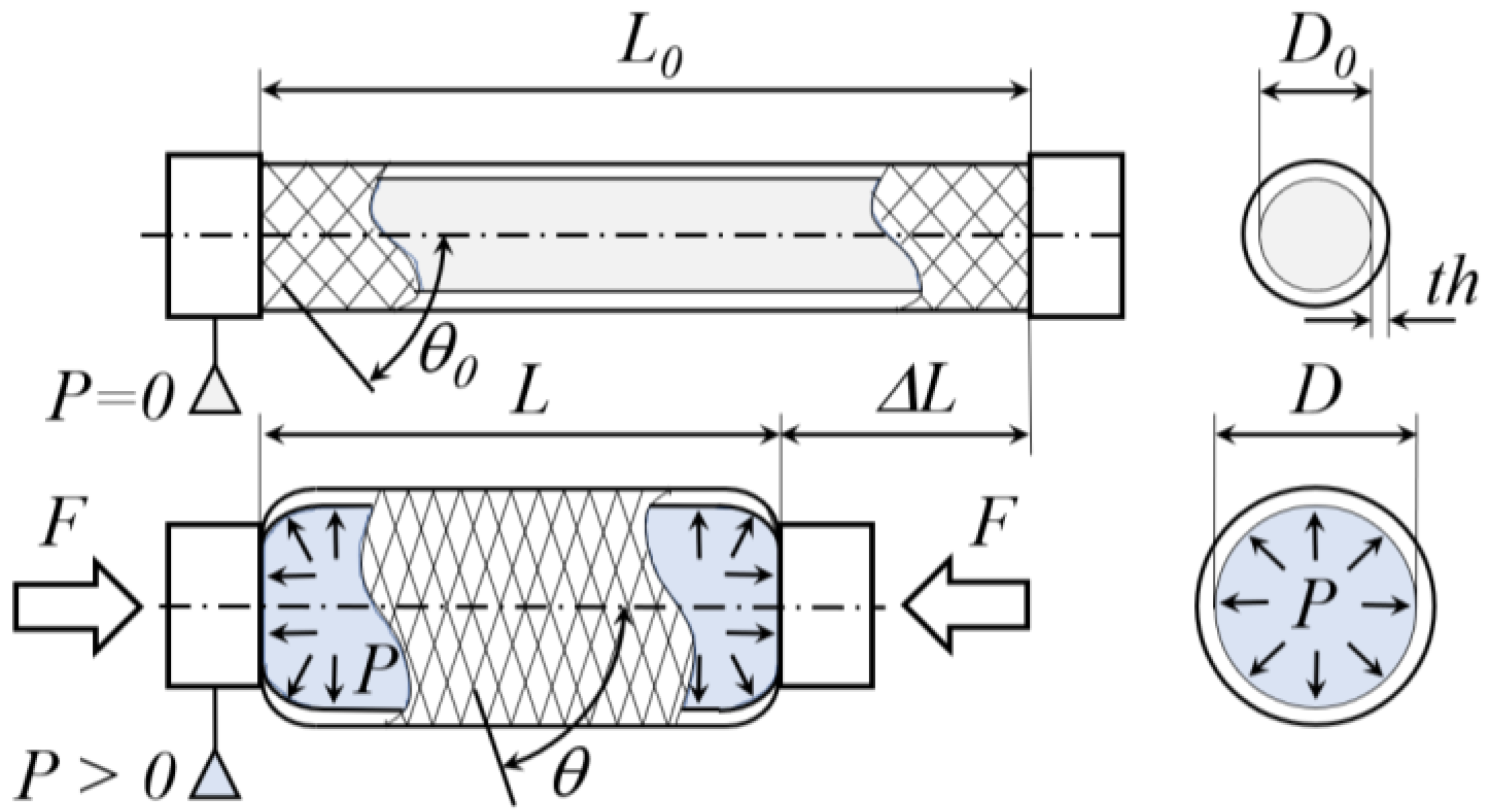
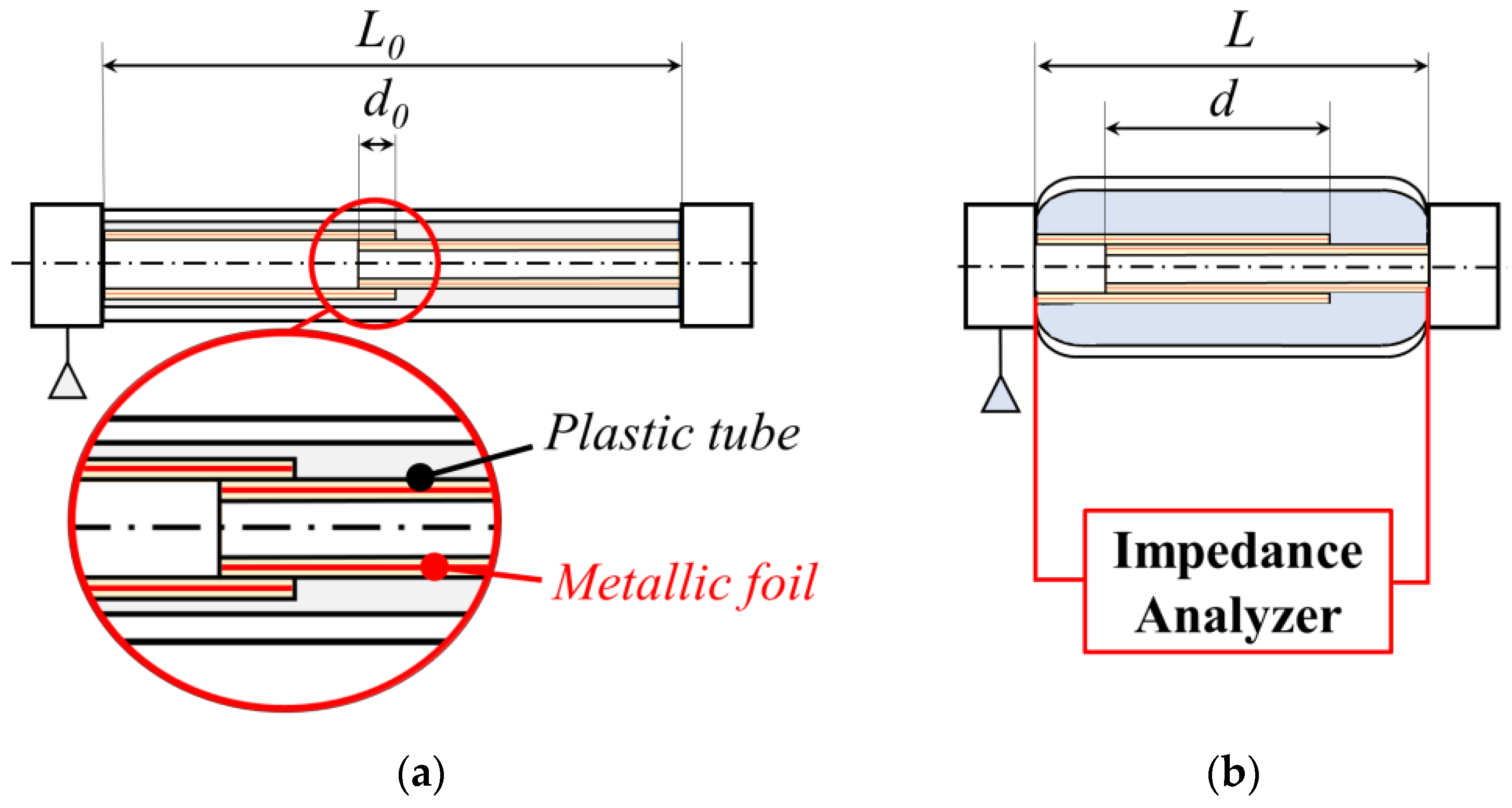
2. The Conceptual Idea

The working principle of a generic MKM is shown in Figure 1, where L0 and L are the muscle undeformed and actual lengths, respectively; D0 and D are the muscle undeformed and actual inner diameters, respectively; th is the thickness of the tube; θ0 and θ are the undeformed and actual angles between the muscle and the threads axes, respectively; P is the muscle inner pressure; and F is the exerted force by the muscle. The grey and cyan-colored areas indicate the inner volumes of the empty tube and the tube filled with compressed air, respectively. The effective length of the muscle is exactly the distance between its two ends.
Due to the presence of the external threads, the inner pressure acts on the cylindrical surface of the tube, causing a radial expansion and a shortening of the muscle. This behavior is counteracted by the force exerted by the pressure acting on the circular inner surfaces of the two tube ends. However, this force can be neglected since the lateral surface of the tube is much greater than the end one. During the deformation, the threads act like a pantograph: the shortening of the muscle causes an increase in the angle θ.
Several analytical formulations have been proposed for modeling the pressure–force–length relationship. According to the hypothesis of an infinite-length muscle, neglecting board effects and friction between the gauze and the inner tube produces the most significant relationship [14]:
F = π D 0 2 P 4 1 sin θ 0 2 3 ( 1 - ε ) 2 cos 2 θ 0 - 1
where ε = Δ L / L 0 is the shortening parameter and Δ L = L 0 L (see Figure 1). Thus, ε ranges from 0 to εmax = 1. Typical values of εmax are around 0.25. Equation (1) allows the two main working modes of an MKM to be identified: (i) the isotonic mode for which the shortening depends on the pressure value for a given external load; (ii) the isometric mode for which the exerted force depends on the pressure value for a given shortening parameter. The characteristic curves for the three values of the external applied force F [18] are reported in Panel (a) of Figure 2 for the isotonic working mode. For the isometric working mode, Panel (b) of Figure 2 shows the value of the exerted force F as a function of the pressure for three values of the given shortening constraint ε. For a given force or shortening parameter, a particular area is observed between the curves obtained for rising and falling values of the pressure. Thus, for both the two working modes, the plots of Figure 2 show a hysteretic behavior of both the effective muscle length and the exerted force due to friction between the threads and the tube, between the threads themselves, as well as to the non-elastic deformation behavior of the tube [1].
Differing from those solutions whose muscle length is related to the deformation of some of its components, in this study, the determination of the muscle length is based on the direct measurements of the actual distance between the two MKM ends. The schematic of the proposed MKM is reported in Figure 3. Referring to Panel (a) of Figure 3, two plastic tubes are inserted one into the other in such a way that the internal diameter of the outer tube is suitably larger than the external inner tube. Thus, the resulting device is a telescopic low-friction system. Moreover, used commercially available plastic tubes contain internally, but close to their internal surface, a metallic foil covering the whole tube’s cylindrical surface. In this way, the telescopic system electrically behaves as a cylindrical capacitor with air and plastic as its dielectric medium whose capacitance is a function of the overlapping area that occurs between the inner and outer plastic tube (see the inset of Panel (a) of Figure 3).
Then, the telescopic system is set in the hollow of a hyper-elastic tube of the MKM. As shown in Panel (b) of Figure 3, if the muscle is pressurized, its total length decreases from L0 to L with a consequent increase at the overlapping region between the inner and outer plastic tubes.
Therefore, the value of the capacitance measured by a conventional impedance analyzer varies directly as a function of the effective overlapping length d between the inner and outer foils of the cylindrical capacitor that can be easily related to the actual muscle length L. It has to be noted that the pressure inside the MKM is related to the muscle length and its variation.
The volume of the entire muscle is filled with compressed air, and the related pressure acts on the cylindrical lateral surface of the hyper-elastic tube. In the case of the MKM of Panel (b) of Figure 3, the activation of the muscle is operated by the effective pressure exerted on the volume of the cylindrical annulus between the outer plastic tube and the hyper-elastic one. Moreover, the proposed MKM configuration could reduce the inner surfaces of the ends where the pressure acts, with the resultant reduction in the force opposing the deformation.

3. Fabrication and Experimental Characterization of the Capacitive Transducers

The fabricated MKM prototypes are based on the four capacitive transducers shown in Figure 4, Panels (a)–(c): three of them are cylindrical capacitors, and the fourth one is a parallel-plate capacitor with the metallic foils positioned on the external surface ends of the inner and outer plastic tubes. The dimensions of the tubes used for all the transducers are reported in Table 1 and were chosen to fabricate MKMs with a total external diameter equal to 30 mm, suitable for collaborative robotics applications [39]. All the prototypes have been experimentally tested with the aim of comparing their properties. The characteristic sizes of the developed capacitive transducers are the following:

3.1. Capacitive Transducer Based on Cylindrical Capacitor Named CC1612

This transducer employs two commercial concentric aluminum tubes with external diameters equal to 16 (outer tube) and 12 mm (inner tube), respectively. A tight-fitting polylactic acid (PLA) bushing, realized by a rapid prototyping technology, is placed at one end of the outer tube to guide the inner tube so as to ensure coaxial displacement. The length of the bushing is equal to 53 mm. The lateral facing surfaces of the two tubes are the capacitor foils, and the air is its dielectric, except for the volume occupied by the bushing, where the dielectric is the PLA. A metallic screw fixes a shielded cable at one end of each tube.

3.2. Capacitive Transducer Based on the Cylindrical Capacitors Named CC2016 and CC2620

These transducers employ two plastic multi-layer tubes usually used for flushing hot water in heating systems. Each tube is composed of three layers: the inner and the outer ones are made of polyethylene that embeds into an aluminum layer (see Panel (c) of Figure 4). The external layer of the inner tube was removed by mechanical turning to reduce the frictional effects that might have affected the sliding of the inner tube within the outer one. The external diameters of the outer and inner tubes of the capacitive transducer CC2016 (CC2620) are equal to 20 mm (26 mm) and 16 mm (20 mm), respectively. The aluminum layers of the two polyethylene are the capacitive foils (i.e., the capacitive plates) of the fabricated cylindrical capacitor whose dielectric is air and polyethylene. A metallic screw fixes a shielded cable at the external ends of both tubes.

3.3. Capacitive Transducer Based on the Parallel-Plate Capacitor Named PPC20

This transducer employs two concentric plastic tubes: the inner one is made of polyethylene and slides into the other one made of polycarbonate. A set of eight plastic screws was placed into the outer tube to maintain them coaxially, as shown in Panel (d) of Figure 4, highlighted within the blue ellipse. A copper disk was glued onto the external end of each of the two tubes. The disks are the capacitor plates, and the air is its dielectric. A shielded cable was welded at the center of each disk.

3.4. The Experimental Characterization

Experimental activities have been carried out to determine the relationships of the capacitance of the different transducers as a function of (i) the overlapping area for the cylindrical capacitors and (ii) the distance between the parallel plate for the plane capacitor. For all the fabricated transducers, their capacitance is directly related to their length.
The impedance analyzer LCR Meter SR715 (Stanford Research Systems with a basic accuracy of 0.2%) was used for measuring the capacitance of each one of the fabricated transducers. The output frequency of the analyzer was set equal to 10 kHz, taking 20 samples per second. It has been verified that the measured values of the transducer capacitance do not change within the entire analyzer output frequency range from 100 Hz to 100 kHz. Two shielded cables connecting the foils of each capacitive prototype were connected to the impedance analyzer inputs. To perform the measurements, the shielded cables and the outer tubes of the transducer were firmly fixed to the laboratory test table in such a way as to allow for a continuous, coaxial, low-friction displacement of the inner tube. A suitable reference metric system, based on graph paper, was adopted to measure the inner tube’s current position (i.e., the displacement) with respect to the outer tube end.
In Panels (a), (b), and (c) of Figure 5, the measured values of the capacitance of the three fabricated transducers are reported as a function of the overlapping length d between the inner and outer foils of the cylindrical capacitor, as before defined in Figure 3.
In Panels (a), (b), and (c) of Figure 5, the measured values of the capacitance of the three fabricated transducers are reported as a function of the overlapping length d between the inner and outer foils of the cylindrical capacitor, as before defined in Figure 3. It must be noted that the values of the transducer capacitance have been achieved by subtracting the one corresponding to the initial value relative to the overlapping distance d0 = 15 mm. After subtracting this initial value, the overlapping distance d was varied from 0 up to 80 mm in steps of 1 mm. For the generic step j, the experimental data are the mean value C ¯ j with the corresponding standard deviation sj were calculated, taking the 20 measured capacitance values repeating 10 times the complete cycle of the transducer elongations followed by compressions from d = 0 to d = 80 mm and vice versa. Under these experimental conditions and without considering the electrostatic effects at the capacitor borders, the transducer capacitance is expected to follow the classical equation
C = 2 π ε 0 ε r d ln ( R 2 / R 1 )
where ε0 is the vacuum permittivity, εr the dielectric relative permittivity, and R1 and R2 are the capacitor’s inner and outer foil radius, respectively. Thus, for fixed values of these parameters, the transducer capacitance depends linearly on the capacitor foil overlapping length d. The result for the CC1612 transducer in Panel (a) of Figure 5 shows that the linear dependence is maintained up to d = 50 mm. The typical standard deviation associated with the measured capacitance is s(CC1612) = 0.6 pF. The dashed line is the linear fitting of the experimental data achieved in the overlapping distance ranging from d = 0 to d = 50 mm. The deviation from linearity might depend on a non-perfect coaxial displacement and/or variations in the diameter of the inner aluminum tube with respect to the outer one. In this respect, from the experimental data, larger values of d are related to an increase in the portion of the inner aluminum tube inside the outer one. Since, for d > 40 mm, the observed values of the capacitance are greater than those ones expected (see the dashed line), this means that the ratio R2/R1 decreases. In this sense, it is easy to verify that a decrease of 1% in this ratio leads to an increase of 3.5% in capacitance. Considering only the capacitance data following the linear fitting dashed line, the resulting sensitivity for the transducer is equal to S(CC1612) = 0.36 pF/mm corresponding to a resolution r(CC1612) = s(CC1612)/S(CC1612) = 1.7 mm. Moreover, the value of the maximum deviation from linearity
E l i n = 100   max 0 d 40   m m C j , exp C j , f i t C d = 40 , f i t
is equal to Elin(CC1612) = 1.53%. Panel (b) of Figure 5 reports the CC(2016) transducer capacitance as a function of the overlapping length d. In this case, there is only a very small deviation from the linearity for values of d > 60 mm. The typical standard deviation of the data is s(CC2016) = 0.23 pF; the sensitivity is equal to S(CC2016) = 0.53 pF/mm, corresponding to a resolution of r(CC2016) = 0.43 mm. The maximum deviation from linearity is equal to Elin(CC2016) = 0.48% for d ranging from 0 to 60 mm. Similarly, Panel (c) of Figure 5 reports the CC(2620) transducer capacitance that follows a linear behavior in the entire range of a variation in the overlapping length d. In this case, the typical standard deviation is s(CC2620) = 0.1 pF and the sensitivity S(CC2620) = 0.31 pF/mm, and the resolution r(CC2620) = 0.32 mm. The maximum deviation from linearity is equal to Elin(CC2620) = 0.58% for d ranging from 0 to 80 mm. For comparison, Panel (d) of Figure 5 shows the variation in the capacitance for the plane–plate transducer PPC20. Now, length d is effectively the distance between the capacitor plates located at the external ends of the inner and outer plastic tube. As expected from electrostatic theory, the response is nonlinear, and the maximum value of the capacitance is about 40 times lower than that achieved by the cylindrical capacitance transducer previously described. The results obtained for these latter suggest that the best option is to use the transducer made of the polyethylene tubes (i.e., the CC2016 and CC2620) that allows for a more coaxial displacement of the inner tube due to the greater value of their diameters with the further advantage of having a relative permittivity two times greater than that one of the vacuum. Furthermore, the achieved resolutions give the possibility of a sub-millimeter fine control to the transducer displacement, and this opens the possibility for the fine control of the elongation and compression of MKMs based on this kind of capacitive transducer. Finally, the use of tubes industrially produced can avoid any deviation from the linear slope of the measured transducer capacitance.

4. The Conceptual Idea

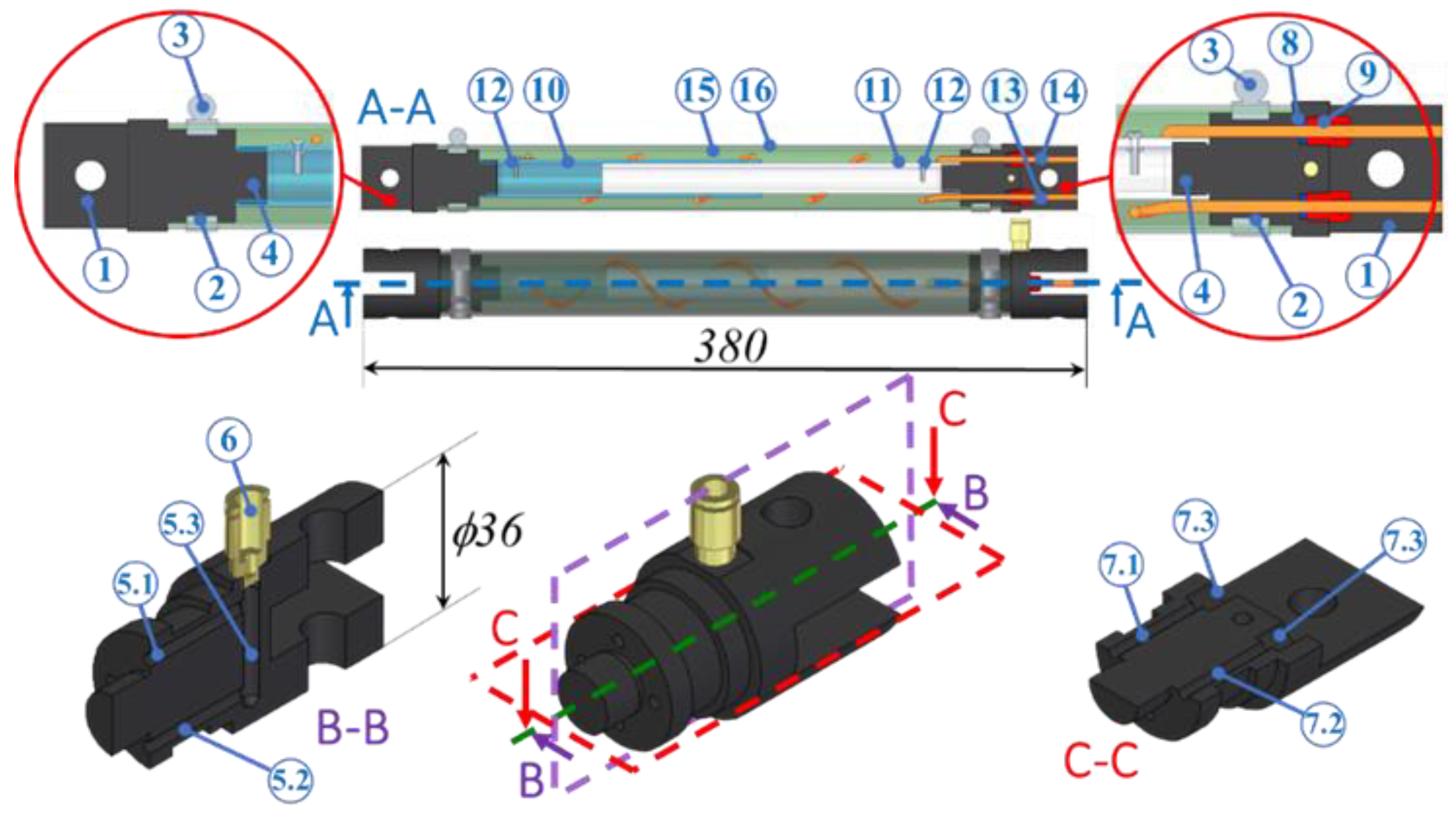
4.1. The Design of the MKM Based on the Cylindrical Capacitive Transducer

The main topic for the development of the proposed novel MKM was focused on the design of the two ends to support the described transducer based on the cylindrical capacitor and to allow the passage of the shielded cables. Moreover, the two ends must ensure mechanical and pneumatic seals. Finally, electrical contact between the wires connecting the capacitor foils and the MKM ends must be avoided.
Referring to Figure 6, the left end (hereinafter called the simple end) is designed to connect one tube of the transducer and ensure the mechanical and pneumatic seals; the right end (hereinafter called the complex end), in addition, must provide for the air inlet/outlet and the passage of the shielded cables. Common features of the two ends are a fork for the connection to the external environment (1), the race (2) for the outer metallic band (3) to ensure the mechanical and pneumatic seals, and a threaded (M18 and M14 for the left and right end, respectively) segment (4). The complex end shows two sets of ducts. The first set is made of three ducts (5.1, 5.2, and 5.3) for the inlet/outlet of the air. The pneumatic fitting (6) completes this set. The second set is made of two ducts (7.1 and 7.2) for the passage of the two cables and two threaded holes (7.3) for their mechanical and pneumatic seals. Such seals, for each cable, are ensured by an O-ring (8) and an internally drilled set screw (9): the cable passes through the set screw whose assembly provides for pushing the O-ring that, in turn, closes the passage of air and applies the necessary contact pressure around the external surface of the cable. Other components of the MKM are the outer (10) and inner (11) tubes of the cylindrical capacitor, two sets of metallic screw-nut-eyelet (12) to connect the cables (13) and (14) to the foils of the capacitor, the hyper-elastic tube (15), and the braided gauze (16). The overall length of the muscle is equal to 380 m; the length of the active part is equal to 285 mm, while the external diameter of the MKM ends is equal to 36 mm.

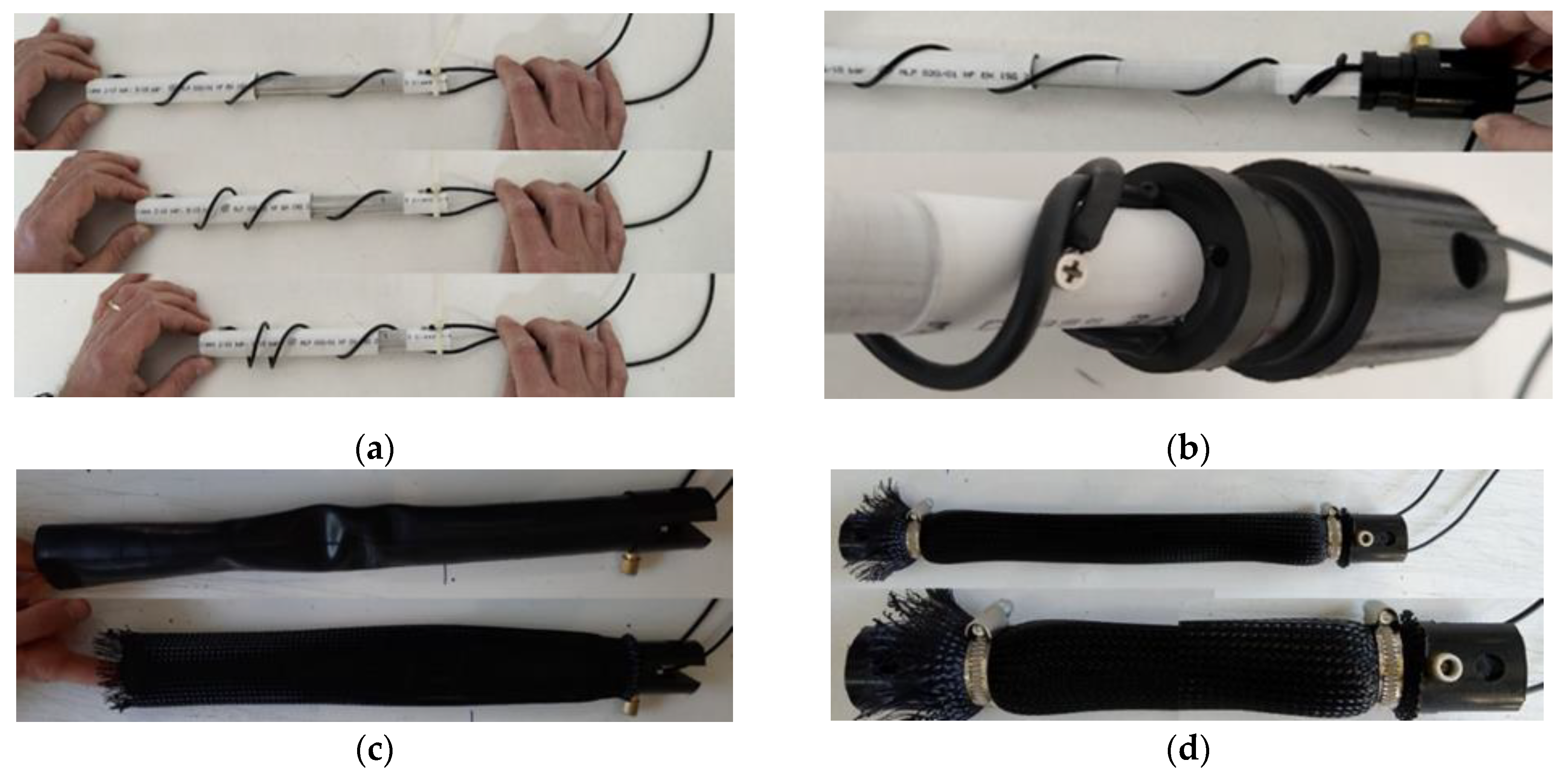
4.2. The MKM Protoype

Both the simple and complex ends are made of filled Teflon to avoid electrical contact between the cables and the complex end. The hyper-elastic inner tube of the MKM is the segment of a commercially available air chamber of a 29″ bike wheel. The braided gauze is made of strands composed of 4 Polyamide 66 threads to form a double helix weaving of 64 spirals. Moreover, two commercially available external metallic bands were adopted together with the pneumatic fitting SMC KQ2H06-M5A, two set screws UNI EN 5925 M8x12, and two O-Rings NBR 1.78 × 2.9. All these employed components are reported in Figure 7.
The assembly procedure proceeded by the following four steps. In the first step, the inner tube of the cylindrical capacitor was inserted into the outer one, and the cable assembled to the latter was wrapped around the two tubes according to a helical path.
As shown in Panel (a) of Figure 8, some forward and backward sliding tests were carried out to check for the proper wrapping of the cable. During these tests, the friction between the inner and outer tubes was verified to be negligible: the inner tube, in fact, slid continuously with no sticking or motion resistance phenomena. In the second step, the complex end was screwed into the inner tube of the cylindrical capacitor. Hence, cables were inserted into the complex end until they exited in correspondence with the fork shape. At this moment, the O-Rings were placed around the cable, and a set of screws were used to fix the end and push the O-rings. Hence, the cables were pushed from the capacitor side and then pulled until the configuration shown in Panel (b) of Figure 8 was reached. In the third step, the cylindrical capacitor was inserted into the hyper-elastic tube, and the resulting assembly was included in the braided gauze. These two actions are shown in Panel (c) of Figure 8. Hence, the metallic band near the complex end was mounted and adjusted to ensure the mechanical and pneumatic seals. In the last and fourth step, the simple end was screwed into the outer tube of the cylindrical capacitor. The capacitor was, thus, moved to reach the axial dimensions of the hyper-elastic tube and the gauze. Finally, the last metallic band was mounted and adjusted, concluding the assembly of the MKM, as shown in Panel (d) of Figure 8, where details of the simple and complex ends are also shown.
It must be noted that during each MKM mounting step, the measurements of the transducer capacitance were performed to check for the system’s proper assembly. In doing this, no problem was recorded since the achieved characteristic curve of the capacitor transducer CC2016 remained unchanged (see Panel (b) of Figure 5).

5. Experimental Characterization of the MKM

A complete experimental characterization was carried out to validate the functionality of the assembled MKM. As shown in Panel (a) of Figure 9, the portal structure testbed (1) was used. It is made of commercial 30 × 30 mm aluminum profiles. A hinge fixes the simple end of the MKM (2) on the upper crossbeam of the testbed. A second hinge fastens the complex end to the slider of an industrial cable linear position transducer (Celesco DV301-0020-111-1110) (3) fixed on the lower crossbeam of the testbed. Particular attention was paid to ensuring coaxiality between the MKM and the capacitive transducer.
The shielded cables exiting the MKM were connected to the LCR Meter SR715 (4). Air was sent into the MKM by a pneumatic line composed of a fine pressure regulator (SMC IR-1000) (5) and a manometer (Nuova Fima DN-100, f.s. 1 bar, resolution 0.02 bar) (6). A pressure transducer (7) (Honeywell ABPMANN004BGAA5, f.s. 4.0 bar, resolution 0.03% f.s.) was also used to measure the MKM pressure. Two voltage power supplies, (8) and (9), were adopted for the linear position and the pressure transducers, respectively. Two digital voltmeters were employed for measuring the linear position output voltage (10) and the pressure transducers (11).
Starting from the 0.00 bar, the pressure was first increased to 0.58 bar in steps of about 0.02 bar and after decreased from 0.58 bar to 0.00 bar. Photographs of the MKM configurations under quasi-static conditions for five values of the internal pressure are reported in Panel (b) of Figure 9.
For each pressure step, the values of the MKM shortening length, the pressure, and the capacitance were measured by the linear position transducer, the pressure transducer, and the LCR meter, respectively. Measurements using the pressure transducer were effective since low-pressure changes occurred with respect to the pressure values imposed by the manometer. The maximum MKM shortening length was equal to 47.8 mm (about 16.8% of L0) at 0.58 bar. After subtracting the value of the capacitance measured for the MKM undeformed condition, the transducer capacitance was found to range from 0 to 22.5 pF.
Panel (a) of Figure 10 reports the response of the proposed MKM to an increase and decrease in the internal pressure showing the typical hysteretic behavior. This behavior has been achieved by measuring the linear position of the MKM (blue curves) and the value of the transducer capacitance (red curves) as a function of the variation in the MKM pressure. Moreover, continuous lines refer to the increase in pressure, while dotted lines refer to the consequent pressure decrease. Note that the shapes of the red and blue curves of both two parameters are quite similar. Moreover, the continuity and the regularity of the curves of Figure 10 suggest that the low friction between the inner and outer tubes of the cylindrical capacitor did not affect the muscle performance and the pressure measurement. From the experimental data of Panel (a) of Figure 10, it is possible to directly relate the transducer capacitance as a function of the MKM shortening length. Since both these two parameters depend on the MKM pressure, a linear correlation is expected. This is demonstrated by observing the results reported in Panel (b) of Figure 10. The least-squares analysis confirms the linear correlation with R2 values equal to 0.9993 and 0.9988 for the rising and falling experimental conditions, respectively. Furthermore, it confirmed the value of the gradients is 0.468 pF/mm and 0.463 pF/mm for the rising and falling experimental conditions, respectively. Finally, the maximum deviations from linearity were found to be 2.44% and 5.22% for the rising and falling experimental conditions, respectively.
These results demonstrate the feasibility, efficacy, and reliability of the proposed MKM employing a transducer based on a cylindrical capacitor. If we recall the experimentally measured resolutions (see Section 3), it is possible to conclude that the proposed MKM can be externally controlled for variations of its length less than 1 mm, which is probably too precise for an MKM due to its viscoelastic behavior.

6. Conclusions

The paper reported on a novel design of a McKibben pneumatic muscle with an embedded capacitive transducer for the continuous measurement of its length. The capacitive transducer is made of two telescopic cylindrical tubes with aluminum-facing surfaces acting as capacitor plates. The determination of the muscle length and its variations is directly provided by measuring the corresponding changes in the transducer capacitance: that is, a linear function of the capacitor plate overlapping area. Unlike the solutions proposed in the literature, the presented capacitive transducer allowed us to directly measure the current length of the muscle, equal to the distance between its ends. A series of experimental tests for three cylindrical capacitive transducers were carried out to find the optimal solution in terms of the achievable sensitivity and length resolution. These parameters are of paramount importance for many industrial and biomedical applications and, in particular, in the field of collaborative robotics. In this sense, the reported and discussed results of the experimental activities demonstrate that the proposed capacitive transducer can control variations in the muscle length relative to its elongation and compression for values less than 1 mm. This is the consequence of the ability to measure the transducer capacitance with a typical statistical relative indetermination better than 0.25%. Moreover, it has been proved that the linear relationship between the actual transducer capacitance and muscle length, with maximum deviations from the linearity, is equal to 2.44% and 5.22% for the muscle elongation and compression working activities, respectively.
In conclusion, the proposed prototype shows the following advantages: it is cheap; all components are market available; the assembly is easy to carry out. Other solutions often require sophisticated fabrication processes and dedicated setups, which can cause production to be laborious and costly. Finally, this solution can be applied to different classes of pneumatic muscles and optimized according to their dimensions.
The next step of the presented research activity will be the design of a mechatronic MKM equipped with a length and a pressure sensor that can generate the input electrical signals of a front-end electronic circuit mounted on a PCB to be integrated into one of the muscle ends. The electronic circuit will be a capacitance-to-voltage converter allowing dedicated microcontroller units to return in real time the actual muscle length.

Author Contributions

Conceptualization, M.G.A. and A.D.M.; methodology, M.G.A. and A.D.M.; validation, M.G.A.; formal analysis, M.G.A. and E.P.; investigation, M.G.A.; data curation, M.G.A. and E.P.; writing—original draft preparation, M.G.A.; writing—review and editing, M.G.A., P.B.Z., A.D.M. and E.P.; supervision, M.G.A. All authors have read and agreed to the published version of the manuscript.

Funding

This research received no external funding.

Data Availability Statement

Not applicable.

Conflicts of Interest

The authors declare no conflict of interest.

References

  1. Daerden, F.; Lefeber, D. Pneumatic artificial muscles: Actuators for robotics and automation. Eur. J. Mech. Environ. Eng. 2002, 47, 11–21. [Google Scholar]
  2. Daerden, F.; Lefeber, D. The concept and design of pleated pneumatic artificial muscles. Int. J. Fluid Power 2001, 2, 41–50. [Google Scholar] [CrossRef] [Green Version]
  3. Durante, F.; Antonelli, M.G.; Beomonte Zobel, P.; Raparelli, T. Development of a straight fibers pneumatic muscle. Int. J. Autom. Technol. 2018, 12, 413–423. [Google Scholar] [CrossRef]
  4. Yang, D.; Verma, M.S.; So, J.H.; Mosadegh, B.; Keplinger, C.; Lee, B.; Khashai, F.; Lossner, E.; Suo, Z.; Whitesides, G.M. Buckling Pneumatic Linear Actuators Inspired by Muscle. Adv. Mater. Technol. 2016, 1, 1600055. [Google Scholar] [CrossRef] [Green Version]
  5. Antonelli, M.G.; Beomonte Zobel, P.; Durante, F.; Gaj, F. Development and testing of a grasper for NOTES powered by variable stiffness pneumatic actuation. Int. J. Med. Robot. Comput. Assist. Surg. 2017, 13, e1796. [Google Scholar] [CrossRef]
  6. Do Rosario Carvalho, A.D.; Karanth, N.P.; Desai, V. Characterization of pneumatic muscle actuators and their implementation on an elbow exoskeleton with a novel hinge design. Sens. Actuators Rep. 2022, 4, 100109. [Google Scholar] [CrossRef]
  7. Liu, X.; Zhang, J.; Xu, F.; Wang, T.; Zhao, L. Design and Modelling of Multi-DOF Manipulator Driven by Hysteresis-Attenuated Pneumatic Artificial Muscles. IEEE Robot. Autom. Lett. 2002, 7, 6447–6454. [Google Scholar] [CrossRef]
  8. Antonelli, M.G.; Beomonte Zobel, P.; D’Ambrogio, W.; Durante, F. Design methodology for a novel bending pneumatic soft actuator for kinematically mirroring the shape of objects. Actuators 2020, 9, 113. [Google Scholar] [CrossRef]
  9. Lo Piccolo, M.V.; Muscolo, G.G.; Ferraresi, C. Use of Pneumatic Artificial Muscles in a Passive Upper Body Exoskeleton. Mech. Mach. Sci. 2002, 106, 78–85. [Google Scholar]
  10. Do Rosario Carvalho, A.D.; Karanth, N.P.; Desai, V. Design and characterization of a pneumatic muscle actuator with novel end-fittings for medical assistive applications. Sens. Actuators A Phys. 2021, 331, 112877. [Google Scholar] [CrossRef]
  11. Antonelli, M.G.; D’Ambrogio, W.; Durante, F. Development of a pneumatic soft actuator as a hand finger for a collaborative robot. In Proceedings of the 2nd International Conference on Mechatronics Systems and Control Engineering, ICMSCE 2018, Amsterdam, The Netherlands, 18–21 February 2018; pp. 67–71. [Google Scholar]
  12. De Volder, M.; Moers, A.J.M.; Reynaerts, D. Fabrication and control of miniature McKibben actuators. Sens. Actuators A Phys. 2011, 166, 111–116. [Google Scholar] [CrossRef]
  13. Schulte, H.F. The characteristic of the McKibben artificial muscle. In The Application of External Power in Prosthetics and Orthotics; National Academy of Sciences, National Research Council, Eds.; Publisher: Washington, DC, USA, 1962; Publication 874, Appendix H; pp. 94–115. [Google Scholar]
  14. Chou, C.P.; Hannaford, B. Measurement and modelling of McKibben pneumatic artificial muscles. IEEE Trans. Robot. Autom. 1996, 12, 90–102. [Google Scholar] [CrossRef]
  15. Tondu, B. Modelling of the McKibben artificial muscle: A review. J. Intell. Mater. Syst. Struct. 2012, 23, 225–253. [Google Scholar] [CrossRef]
  16. Sarosi, J.; Biro, I.; Nemeth, J.; Cveticanin, L. Dynamic modeling of a pneumatic muscle actuator with two-direction motion. Mech. Mach. Theory 2015, 85, 25–34. [Google Scholar] [CrossRef]
  17. Antonelli, M.G.; Beomonte Zobel, P.; D’Ambrogio, W.; Durante, F.; Raparelli, T. An analytical formula for designing McKibben pneumatic muscles. Int. J. Mech. Eng. Technol. 2018, 9, 320–337. [Google Scholar]
  18. Antonelli, M.G.; Beomonte Zobel, P.; Durante, F.; Raparelli, T. Numerical modelling and experimental validation of a McKibben pneumatic muscle actuator. J. Intell. Mater. Syst. Struct. 2017, 28, 2737–2748. [Google Scholar] [CrossRef]
  19. Iwata, K.; Suzumori, K.; Wakimoto, S. A method of designing and fabricating McKibben muscles driven by 7MPa hydraulics. Int. J. Autom. Technol. 2012, 6, 482–487. [Google Scholar] [CrossRef]
  20. Nozaki, T.; Noritsugu, Y. Motion analysis of McKibben type pneumatic rubber artificial muscle with finite element method. Int. J. Autom. Technol. 2014, 8, 147–158. [Google Scholar] [CrossRef]
  21. Dzedzickis, A.; Subačiuté-Žemaitié, J.; Šutinys, E.; Samukaité-Bubniené, U.; Bučinskas, V. Advanced Applications of Industrial Robotics: New Trends and Possibilities. Appl. Sci. 2022, 12, 135. [Google Scholar] [CrossRef]
  22. Available online: https://sps.honeywell.com/it/it/products/advanced-sensing-technologies/healthcare-sensing/board-mount-pressure-sensors/basic-abp-series (accessed on 18 October 2022).
  23. Available online: https://www.te.com/usa-en/product-CAT-FSE0006.html?q=FX29&source=header (accessed on 18 October 2022).
  24. Tomori, H.; Hiyoshi, K. Control of Pneumatic Artificial Muscles Using Local Cyclic Inputs and Genetic Algorithm. Actuators 2018, 7, 36. [Google Scholar] [CrossRef] [Green Version]
  25. Durante, F.; Beomonte Zobel, P.; Raparelli, T. Two-Dof Upper Limb Rehabilitation Robot Driven by Straight Fibers Pneumatic Muscles. Bioengineering 2022, 9, 377. [Google Scholar] [CrossRef]
  26. Takosoglu, J.E.; Laski, P.A.; Blasiak, S.; Bracha, G.; Pietrala, D. Determining the Static Characteristics of Pneumatic Muscles. Meas. Control 2016, 49, 62–71. [Google Scholar] [CrossRef]
  27. Doumit, M.D.; Pardoel, S. Dynamic contraction behaviour of pneumatic artificial muscle. Mech. Syst. Signal Process. 2017, 91, 93–110. [Google Scholar] [CrossRef]
  28. Zhong, S.; Gai, Z.; Yang, Y.; Zhao, Y.; Qi, Y.; Yang, Y.; Peng, Y. A contraction length feedback method for the McKibben pneumatic artificial muscle. Sens. Actuators A. Phys. 2022, 334, 113321. [Google Scholar] [CrossRef]
  29. Kuriyama, S.; Ding, M.; Kurita, Y.; Ueda, J.; Ogasawara, T. Flexible Sensor for McKibben Pneumatic Artificial Muscle Actuator. Int. J. Autom. Technol. 2009, 3, 731–740. [Google Scholar] [CrossRef]
  30. Yano, T.; Fujimoto, S.; Akagi, T.; Kobayashi, W. Development of Outer Diameter Sensor for Position Control of McKibben Artificial Actuator Using Hall-effect Sensor. Int. J. Mech. Eng. Robot. Res. 2020, 9, 190–196. [Google Scholar] [CrossRef]
  31. Akagia, T.; Dohtaa, S.; Kenmotsua, Y.; Zhaob, F.; Yonedac, M. Development of smart inner diameter sensor for position control of Mckibben artificial muscle. Procedia Eng. 2012, 41, 105–112. [Google Scholar] [CrossRef] [Green Version]
  32. Tiziani, L.O.; Hammond, F.L., III. Optical Sensor-Embedded Pneumatic Artificial Muscle for Position and Force Estimation. Soft Robot. 2020, 7, 462–477. [Google Scholar] [CrossRef]
  33. Felt, W.; Chin, K.Y.; Remy, C.D. Contraction Sensing with Smart Braid McKibben Muscles. IEEE/ASME Trans. Mechatron. 2016, 21, 1201–1209. [Google Scholar] [CrossRef] [Green Version]
  34. Erin, O.; Pol, N.; Valle, L.; Park, Y.L. Design of a bio-inspired pneumatic artificial muscle with self-Contained sensing. In Proceedings of the 38th Annual International Conference of the IEEE Engineering in Medicine and Biology Society (EMBC), Orlando, FL, USA, 16–20 August 2016; pp. 2115–2119. [Google Scholar]
  35. Ho, V.A.; Hirai, S. Measuring mcKibben actuator shrinkage using fiber sensor. In Proceedings of the 24th IEEE International Symposium on Robot and Human Interactive Communication, Kobe, Japan, 31 August–4 September 2015; pp. 628–633. [Google Scholar]
  36. Felt, W.; Remy, C.D. Smart Braid: Air Muscles that Measure Force and Displacement. In Proceedings of the 2014 IEEE/RSJ International Conference on Intelligent Robots and Systems (IROS 2014), Chicago, IL, USA, 14–18 September 2014; pp. 2821–2826. [Google Scholar]
  37. Legrand, J.; Loenders, B.; Vos, A.; Schoevaerdts, L.; Poorten, E.V. Integrated Capacitance Sensing for Miniature Artificial Muscle Actuators. IEEE Sens. J. 2020, 20, 1363–1372. [Google Scholar] [CrossRef]
  38. Kanno, R.; Watanabe, S.; Shimizu, K.; Shintake, J. Self-Sensing McKibben Artificial Muscles Embedded with Dielectric Elastomer Sensor. IEEE Robot. Autom. Lett. 2021, 6, 6274–6280. [Google Scholar] [CrossRef]
  39. Antonelli, M.G.; Zobel, P.B.; Durante, F.; Zeer, M. Modeling-Based EMG Signal (MBES) Classifier for Robotic Remote-Control Purposes. Actuators 2022, 11, 65. [Google Scholar] [CrossRef]
Figure 1. The working principle of the MKM detailing its significant geometrical and functional parameters.
Machines 10 01156 g001
Figure 2. Characteristic curves of the MKM operating modes. Panel (a) the isotonic working mode for three different values of the exerted force F; Panel (b) the isometric working mode for three different shortening constraints ε.
Machines 10 01156 g002
Figure 3. Schematic of the proposed MKM. Panel (a): the muscle at rest with length L0. Here, d0 indicates the overlapping of the two cylindrical capacitor foils. In the inset, a magnification of the cylindrical capacitor structure is visible; Panel (b) the muscle compressed for an actual length L < L0 and d > d0.
Machines 10 01156 g003
Figure 4. The prototypes of the capacitive transducers: Panel (a) the cylindrical capacitive transducer CC1612; Panel (b) the cylindrical capacitive transducer CC2620 (the CC2016 transducer is similar, differing only for the tube diameters); Panel (c) a detail of the multi-layer polyethylene tube; Panel (d) the parallel-plane capacitive transducer PPC20.
Machines 10 01156 g004
Figure 5. Experimental characteristic curves of the developed capacitive transducers: Panel (a) CC1612 transducer; Panel (b) CC2016 transducer; Panel (c) CC2620 transducer; Panel (d) PPC20 transducer.
Machines 10 01156 g005
Figure 6. Section views of the designed MKM and section isometric views of the complex end.
Machines 10 01156 g006
Figure 7. Components of the proposed MKM: (1) hyper-elastic tube; (2) braided gauze; (3) couple of metallic bands; (4) simple end; (5) complex end with the pneumatic fitting previously assembled; (6) outer and (7) inner tubes of the cylindrical capacitor CC2016; shielded cables previously assembled to the outer (8) and inner (9) tubes of the capacitor CC2016; (10) couple of O-Rings; (11) couple of internally drilled set screws.
Machines 10 01156 g007
Figure 8. Steps for the assembly procedure of the proposed MKM: (a) assembly of the capacitive transducer and wrapping of one shielded cable; (b) assembling of the capacitive transducer and the cables to the complex end; (c) assembling of the hyper-elastic tube and the braided gauze; (d) the assembled prototype of the MKM and details of the two ends.
Machines 10 01156 g008
Figure 9. Experimental validation of the proposed MKM: (a) the employed testbed; (b) Photographs of the MKM configurations for five different internal pressure values.
Machines 10 01156 g009
Figure 10. Experimental characterization of the proposed MKM. Panel (a): MKM shortening length and transducer capacitance as a function of the pressure; Panel (b): Correlation between the transducer capacitance and the MKM shortening length with the results of the linear fitting procedure.
Machines 10 01156 g010
Table 1. Dimensions in [mm] of the proposed capacitance transducers.
CC1612CC2016CC2620PPC20
Outer tube
External diameter16202628
Thickness1232
Length200175205500
Aluminum diameter/1824/
Disk diameter///31
Disk thickness///2
Inner tube
External diameter12162020
Thickness1221.5
Length188218122550
Aluminum diameter/1519/
Disk diameter///20
Disk thickness///2
Publisher’s Note: MDPI stays neutral with regard to jurisdictional claims in published maps and institutional affiliations.

