Article

Mechanism Design and Experimental Verification of Novel Automatic Balance Equipment for a Rope-Type Elevator

1
School of Mechanical Engineering, Shandong University of Technology, No. 266 West Xincun Road, Zibo 255049, China
2
School of Mechanical and Aerospace Engineering, Gyeongsang National University, 501 Jinju-daero, Jinju-si 52828, Republic of Korea
3
School of Transportation and Vehicle Engineering, Shandong University of Technology, Zibo 255000, China
4
Tianrun Industrial Technology Co., Ltd., Weihai 264200, China
*
Authors to whom correspondence should be addressed.
Machines 2022, 10(12), 1180; https://doi.org/10.3390/machines10121180
Submission received: 11 November 2022 / Revised: 1 December 2022 / Accepted: 6 December 2022 / Published: 7 December 2022
(This article belongs to the Section Machine Design and Theory)

Abstract

:
Multi-rope elevators are widely used in modern buildings. However, problems such as vibration, noise, uneven wear of key components and shortened life caused by the uneven distribution of rope tensions are still unsolved in the elevator industry. In order to balance the different tensions and the axial deformation of each rope, a novel automatic balance equipment for rope-type elevators (NABE-RE) is proposed in this article. Simulations based on the Simscape numerical methodology are used to verify the kinematic rationality of the proposed mechanism. The optimal structural stability of the core components is evaluated through a series of investigations based on the finite element method. Additionally, the manufactured prototypes are put through a series of comparison experiments to evaluate their tension balancing performance. The results show that the unbalance rate of the system is effectively limited to a low level, thus verifying the feasibility of the automatic tension balancing function of the proposed NABE-RE.

1. Introduction

The development of technology has brought various conveniences to our lives. As one of the most representative designs, the elevator has laid the indispensable foundation for modern buildings such as skyscrapers.
The rope type traction drive elevator is mainly based on the principle of a simple pulley system. The car on one side of the pulley is connected to the counterweight on the other side with ropes. Under the combined action of the friction generated between the pulley and ropes, the elevator can be driven by a motor to overcome the potential energy of gravity to perform the up and down vertical movement. Rope-type elevators are primarily composed of a machine room with a controlling system, a people carrying car, an electric motor, a well and rails. Although the elevator has a history of more than 130 years since its appearance, various problems such as safety, noise, vibration, durability, efficiency, etc. are still emerging [1,2,3]. In the final analysis, these issues are brought on by the ropes’ varying tensions, which causes wear and relative sliding between the ropes and pulleys [4,5,6]. The elevator system’s durability and life are decreased as a result of the ropes’ wear and tear. In addition, the passenger car experiences vibration and shaking as a result of the relative sliding of the ropes and pulley, which also contributes to the elevator’s poor running smoothness. More and more scholars are now involved in research aimed at improving the performance of all aspects of elevator design [7,8,9,10,11].
Santo et al. studied the horizontal nonlinear dynamic response of high-speed elevators and proposed a control strategy based on the State-Dependent Ricatti Equation (SDRE) to improve the vibration in the car [12]. Gerstenmeyer and Peters reviewed a series of the theoretical and mathematical research needed to determine controlled stopping positions and safety distances for elevator control in a multi-car elevator system [13]. As a conclusion, the minimum allowable distance between two cars during normal operation was calculated. Kim et al. proposed a more efficient transfer operation system (TOS) for elevators in irregularly shaped high-rise building constructions, which minimized the waiting time and operating costs [14]. Elevator Talk, an elevator development and management system based on the Internet of Things (IoT), was proposed by Van et al. It allows elevators to quickly make decisions within 0.2010 milliseconds, thereby improving the elevator performance [15]. Wang et al. conducted seismic analysis of the elevator rail and counterweight system and concluded from the results that increasing the stiffness ratio does not necessarily improve the seismic performance of the counterweight system [16].
In the rope-type elevator, in order to obtain a greater load allowance and improve the safety, multiple parallel ropes are usually used to disperse the great traction load. However, the use of multiple parallel ropes results in different axial deformations of the ropes due to different boundary factors, which can cause their lengths to become inconsistent, resulting in uneven tension transmission. This phenomenon is an important cause of problems such as uneven wear of the pulley, component noise and vibration, shortened system life and inaccurate elevator positioning [17,18,19,20,21,22,23,24]. In order to solve the problem of different lengths of parallel ropes, the design of a spring socket installed at the end of the rope to connect to the passenger car and the counterweight is proposed [25]. However, the tension balance between the ropes is unaffected by this type of construction, which can only balance the length of the ropes. In other words, variable tension will result in various friction coefficients for the ropes and pulleys, which will cause partial wear, slight relative sliding and other issues. Therefore, maintaining equalized tension on each rope while maintaining the balance of rope length is the important strategy for enhancing the system’s durability and ride comfort.
In the current study, the mechanism design of the novel automatic balance equipment for rope-type elevators (NABE-RE) is proposed, which can automatically adjust the tension on each rope so that the tension transmitted from the counterweight can be evenly distributed over the ropes.
In order to verify the kinematic validity of the proposed NABE-RE mechanism, a kinematic simulation was performed using the Simscape numerical investigation tool, which is a professional multi-physics kinematics simulation software based on the Matlab platform. In addition, a series of numerical analyses based on the finite element method are carried out to verify the structural stability of the core components of the proposed NABE-RE design. Furthermore, the representative prototypes of the five rope-type NABE-RE are manufactured and bench tested to observe and validate the performance of the automatic rope tension adjustment function. The numerical simulation and empirical results show that the proposed mechanism of NABE-RE can automatically adjust the tension, keeping the unbalanced tension on each rope to less than 10%.

2. Mechanism Design

2.1. Operating Principle

The conventional balancing equipment for elevator ropes can only adjust according to the different axial deformation of ropes without having any effect on the tensions in the ropes. Uneven tensioning of the ropes can lead to a shortened service life, increased vibration, uneven wear of the elevator core components and many other problems. To solve this problem, the NABE-RE is proposed in this research. This section introduces and discusses the mechanical operating principles of the proposed NABE-RE design. The proposed design is compared with the conventional spring socket to elaborate on its design features more intuitively.
Figure 1a,b respectively show the schematic diagrams of the conventional spring socket and the NABE-RE. It is assumed that, due to the influence of boundary factors, the amount of axial deformation of the rope on the left is larger than that of the rope on the right.
In the conventional spring socket (as shown in Figure 1a), the tension passes through the rigid connection between the end of the rope and the spring, causing the spring to experience a linear compression. As the length of the left side rope is longer while the coefficients of elasticity of the two springs are same (k1 = k2), so, according to Hooke’s law, the compression deformation of the left side spring (x1) is less than that of the right side spring (x2). Therefore, it can be seen that in the equilibrium state of the conventional spring socket, the tension (T2) of the right side rope is greater than the tension (T1) of the left side rope. In other words, the conventional spring socket does not have an automatic adjustment function for the tension in the ropes.
As shown in Figure 1b, the NABE-RE is mainly composed of high stiffness spring vibration isolators and automatic tension adjustment hydraulic cylinders. Similar to the conventional spring socket, the tensions transmitted from the ropes act on the high stiffness springs and cause the compression deformation of springs. The other end of each spring is fixed to the hydraulic cylinder shaft. The chambers of the two hydraulic cylinders are connected to each other through an orifice to form a hydraulically coupled system. When the length of the left side rope is increased, the length of the right side rope is relatively shortened. According to Hooke’s law, at this time, the elastic force F4 of the right side spring is greater than the elastic force F3 of the left side spring. As a result of the difference in forces acting on the springs on both sides, the hydraulic cylinder shafts are moved to find the new equilibrium position of the total system. According to Pascal’s principle, the pressure of the hydraulic oil acting on the two piston surfaces of the hydraulic system must be the same (P1 = P2) when the system is in a balanced state. Therefore, the hydraulic thrusts acting on the two springs must also be the same. The springs 3 and 4 are assumed to be identical in this study. Since the system is in equilibrium, the force acting on each end of the spring should be equal, meaning that springs 3 and 4 should exhibit equal spring force providing tension to the rope (F3 = F4 = T1 = T2). Thus the relationship of forces in the entire system in equilibrium state can be sorted as follows:
P 1 · A = P 2 · A = F 3 = F 4 = T 1 = T 2 = m g P n
Here, P1 and P2 respectively represent the pressure (Pa) of the hydraulic oil acting on the left and right hydraulic cylinder shafts, A is the area (mm2) under hydraulic pressure of the two hydraulic pistons, F3 and F4 (N) respectively represent the elastic forces on the left and right springs, T1 and T2 (N) respectively represent the tensions on the left and right ropes, m represents the mass of one passenger (kg), P represents number of passengers allowed, g represents the gravitational acceleration and n represents the number of cylinders in the NABE-RE.
It can be seen from Equation (1) that the NABE-RE can respond quickly to the differences in lengths and tensions of the ropes to find a new balance position, which has the function of automatically adjusting the different tensions acting on the ropes to a uniform value. In the next section, kinematic investigation based on a numerical simulation method is used to verify the correctness of this design.

2.2. Kinematic Verification

Kinematic simulation is often used to verify the performance of a new mechanism [26]. In this study, the mechanism modeling and kinematic verification based on numerical simulation technology are carried out to confirm the rationality and effectiveness of the proposed NABE-RE design.

2.2.1. Modeling and Investigation Methods

The Simscape module based on the Matlab Simulink platform provides a convenient block diagram based operating environment for modeling and simulation, which has gradually become mainstream commercial software for multi-physics mechanism analysis [27]. The NABE-RE presented in this study is mainly composed of two kinds of physics: hydraulic physics and rigid-body physics. The mechanism model can be conveniently established using the example elements provided in Simscape. Through the built-in numerical investigation method solver, the simulation of the effectiveness of the kinematics can more accurately be performed [28]. In this study, the kinematics verification analysis was performed on a workstation equipped with a 2.6 GHz Intel Xeon E5 2690 v4 processor and 128 GB RAM. Since the purpose of this section is only to verify the rationality of the kinematics of the system, we have adopted the same design specifications for all the hydraulic cylinders and springs. Furthermore, in order to save time during modeling and simulation, the NABE-RE design with only two cylinders, as shown in Figure 1b and explained in Section 2.1, was considered for the calculations presented in this section.
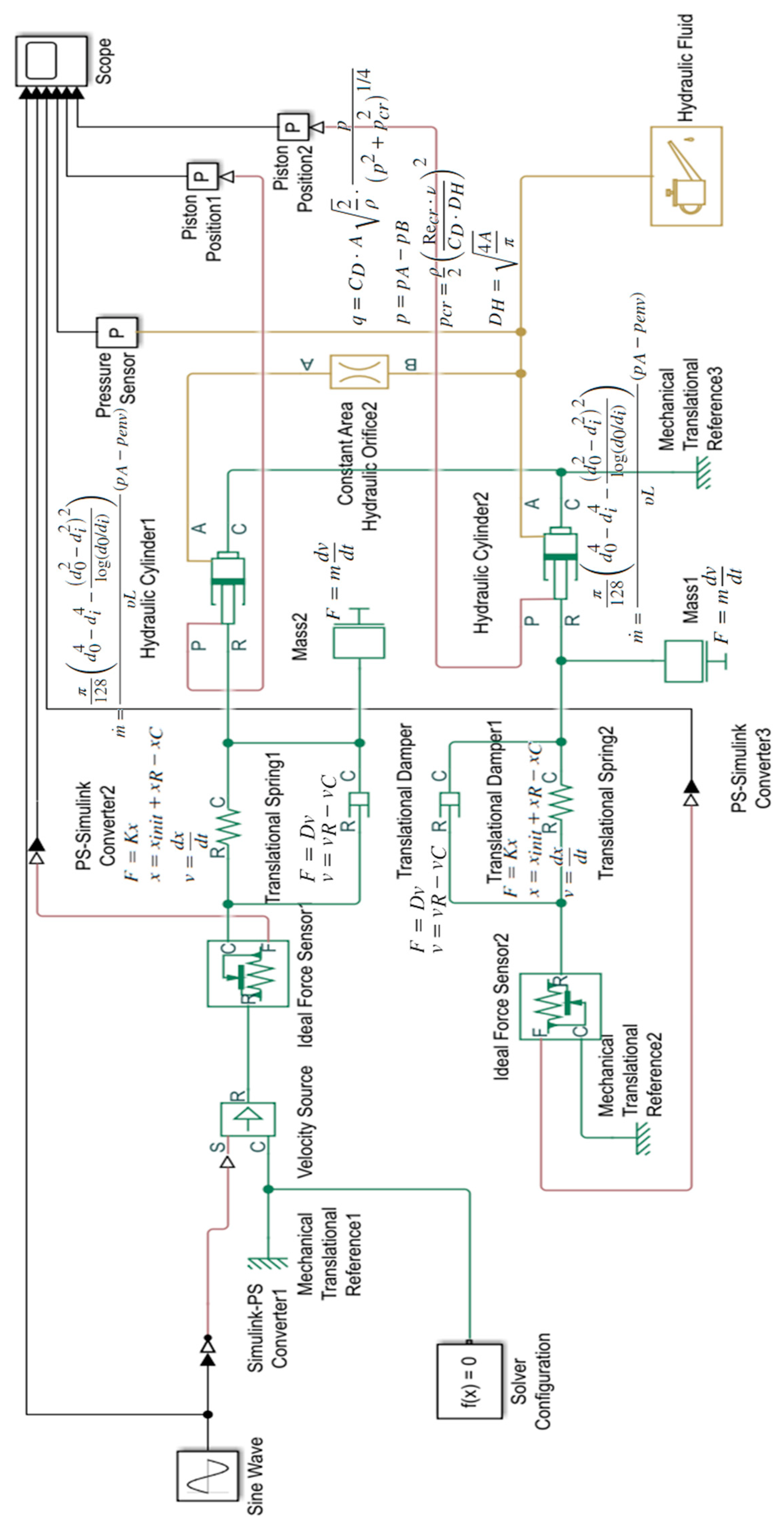
Figure 2 shows the established Simscape model of the NABE-RE design. In this model, the specifications of the hydraulic cylinders and spring vibration isolators in the upper and lower sub-systems are identical. The springs are connected in series with their respective hydraulic cylinder shafts. The translational damper connected in parallel with the spring in the figure represents the inherent structural damping of the high stiffness spring. Due to the fact that the orifice connecting the two hydraulic cylinders is set to a suitably large value and that the transition state in the actual equilibrium process is sufficiently protracted, the damping effect brought on by the transient fluid velocity may be disregarded in this investigation.
In order to observe the balancing effect of the NABE-RE mechanism on the changes in tension and axial deformation taking place in each rope, the lower subsystem is set to be relatively static at the end of the spring. To evaluate the system response, the relative speed of the sine waveform shape shown in the following formula is applied to the end of the spring of the upper subsystem.
V = 10 · Sin 1.34 · t
Here, V represents the speed (mm/s) and t represents the time (s).
The main parameters that have an impact on the simulation results are set as stated in Table 1, taking into consideration the tension and other characteristics of the elevator rope in practical application. The liquid pressure will rise when motion displacement is imparted to one side of the cylinder shaft. The hydraulic pressure will push the cylinder shaft to the opposite side in order to overcome the spring elastic force and reach a new equilibrium position according to the communicating vessels principle.
The housings of the two hydraulic cylinders are connected to each other and fixed to the ground. ISO VG 32 hydraulic oil, which is commonly used in the hydraulic industry, is used in the hydraulic system of NABE-RE. In this study, the fluid was considered to be incompressible. The ode 23t solver based on ordinary differential equations (ODE) and differential algebraic equations (DAE) was used to solve the kinematics verification simulation. Sensor modules for parameters such as spring force, hydraulic pressure and piston displacement were also added to the model to observe the simulation results.

2.2.2. Simulation Results and Discussion

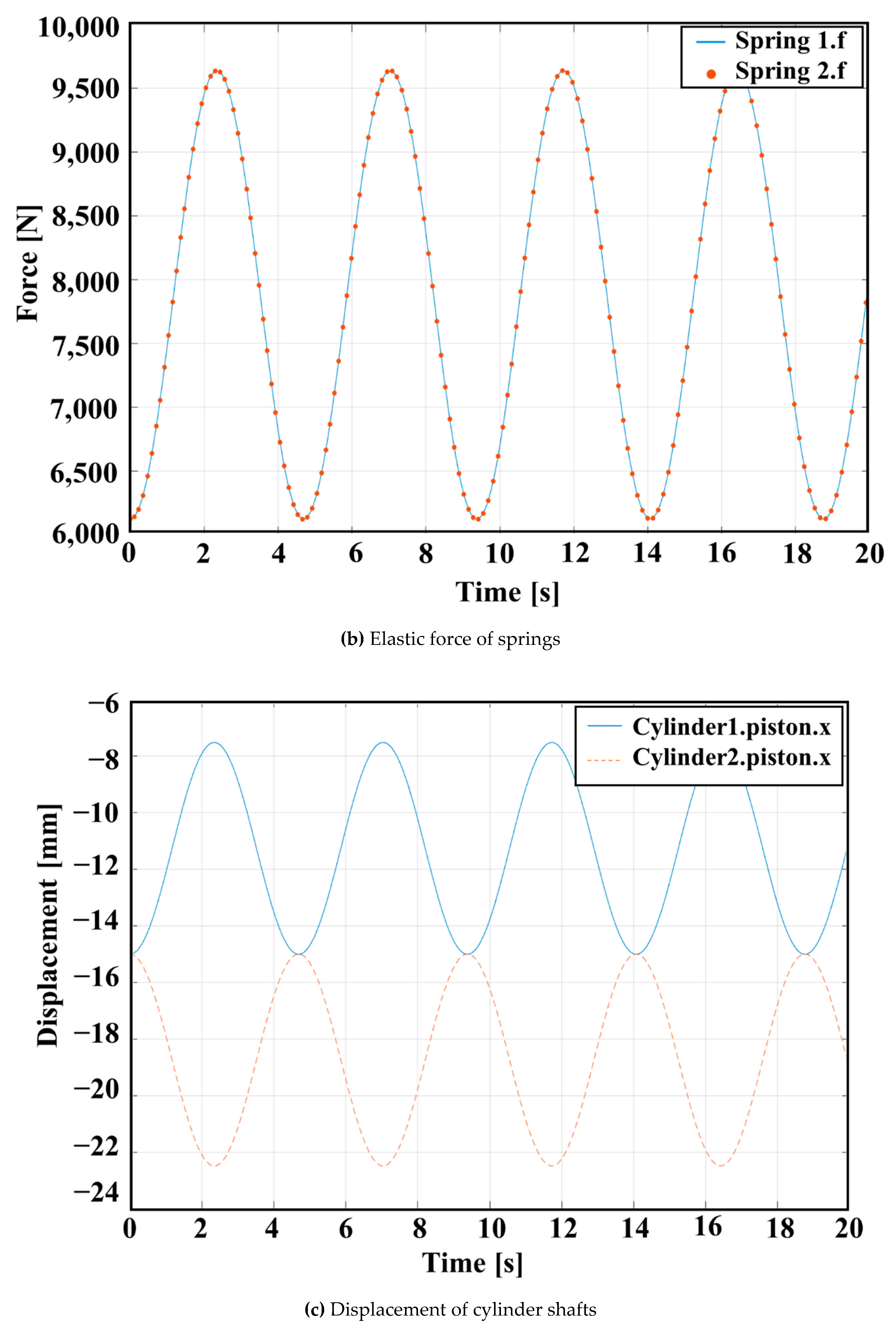
Figure 3a,b show the compression deformation and elastic force of the two high stiffness springs. The solid and dotted lines represent spring 1 and spring 2 respectively. As the speed of the sinusoidal change is the input to spring 1, it is easy to infer that spring 1 should exhibit the regular sinusoidal deformation and spring force changes consistent with the input. As shown in Figure 3a, the deformation changes of the two high stiffness springs show consistent periodical change between the preload value of 13.0 mm and the peak value of 20.5 mm. The comparison results of the elastic force of springs shown in Figure 3b can be obtained according to Hooke’s law. The minimum elastic force is 6121 N and the maximum elastic force is 9653 N. It can be seen that the cyclic changes of the deformation and elastic force of the two springs are consistent with the input speed curve, so it can be concluded that the power of the entire NABE-RE mechanism has achieved normal transmission.
Figure 3c shows the displacement results of the two hydraulic cylinder shafts. The solid and dotted lines indicate hydraulic cylinder shaft 1 and hydraulic cylinder shaft 2, respectively. It can be seen from the results’ comparison curve that the frequency of displacement change of the two hydraulic cylinder shafts is the same, but their direction of movement is opposite. Moreover, the change curves of the two shafts are symmetrical along the displacement of −15.0 mm, which is the preset initial position of the shafts in the hydraulic cylinders.
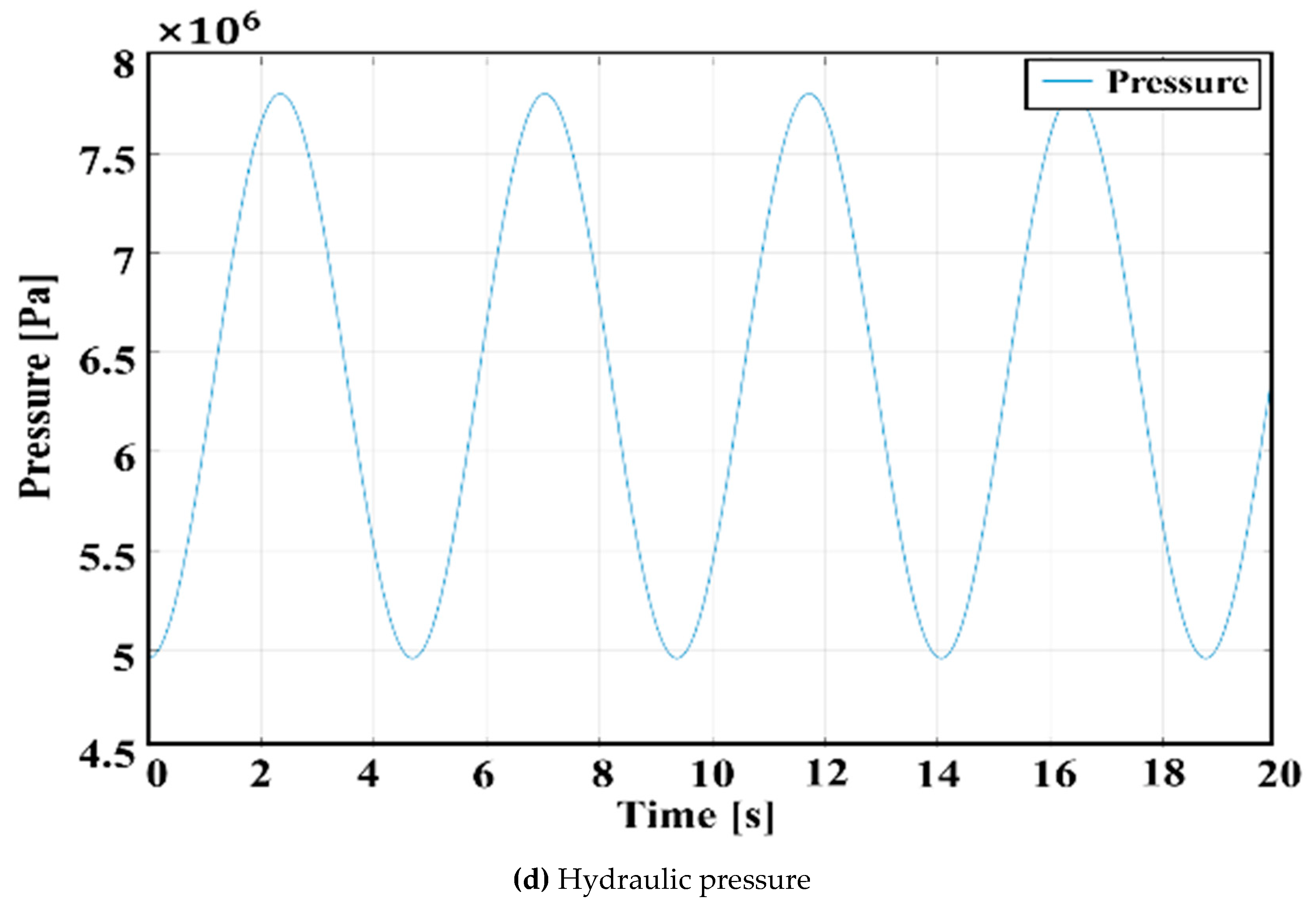
The elastic force that is generated by the compression of spring 1 will push the hydraulic oil to increase the pressure of the entire hydraulic system. The change curve of system hydraulic pressure is shown in Figure 3d. In this study, as the compressibility of the oil is not considered, if the volume of cylinder 1 is reduced, the high pressure will push the oil to flow into cylinder 2 through the orifice. The increase of hydraulic oil in cylinder 2 will generate a high pressure in the limited volume and push cylinder shaft 2 to move outwards. This will force spring 2 to compress, thus producing a change in the elastic force.
Since the change frequency of all the results is consistent with the input velocity curve, the rationality of the kinematic design of the NABE-RE is proved. According to the displacement results of the cylinder shaft, it can be seen that the NABE-RE has the function of automatically adjusting the ropes with different axial deformations, like a conventional spring socket. In addition, it can be proven from the elastic force curves of input spring 1 and output spring 2 that the NABE-RE mechanism has the function of automatically balancing the tension in each rope.

3. Verification of NABE-RE

In this study, a series of numerical and experimental investigations were conducted on the proposed NABE-RE with five cylinders for a 20-passenger rope-type elevator. Due to their convenience, low cost, high efficiency and accuracy, numerical investigation methods are widely used in various industrial fields to verify the structural reliability of mechanical products during development. The performance test method developed to verify the tension balance function of the NABE-RE for each rope is presented in this chapter.

3.1. Numerical Investigation of Structural Stability

Considering the actual number of passengers and the safety factor of the core components, the optimal design parameters of NABE-RE were calculated by integrating the optimal design theory of the housing, cylinder shaft and rope socket.

3.1.1. Modeling and Investigation Methods

With ever-improving computer technology, simulation technology has also seen many innovations [29,30,31,32]. Among these, the finite element method (FEM) plays an important role in solving structural stability problems of machinery and materials [33]. In this study, the structural stability of the core components of the proposed NABE-RE was numerically investigated and discussed separately by using FEM. Considering the working characteristics of the housing base, the cylinder shaft and the rope socket of the NABE-RE in actual operation, the mechanical module provided by ANSYS was used in this study to discuss the stability of these three core components of the proposed design.
The NABE-RE system’s three-dimensional modeling is depicted in Figure 4. As can be observed, the hydraulic housing base, the cylinder shaft, the high-stiffness springs and the rope make up the NABE-RE system. It should be clear that the housing base primarily bears the action of hydraulic pressure, the rope socket primarily bears the action of spring pressure and rope tension, and the cylinder shaft primarily bears the combined action of hydraulic pressure and spring pressure. Therefore, the complex mechanical problems could be reduced to simple strength problems on each core component in order to study the impact of specific forces on various core components. To simplify the computation, the liquid pressure is equivalent to the continuous pressure acting on the solid–liquid interfaces and the effect of the spring is equivalent to the elastic force acting on the two contact surfaces. The input parameters are identical to those in Table 1, which was computed by taking into account the design requirement of the elevator, in order to guarantee consistency of the results. Table 2 shows the mechanical properties of the materials used for each core component. Considering that the rope socket and the cylinder shaft are directly connected to the rope and have to transmit the tension, carbon steel materials S45C and SS41 with high yield strength were used respectively for these components. The housing base mainly supports the pressure load of the internal hydraulic cylinder and, considering the requirement of stiffness and weight, the material AL-6063 T5, which is widely used in the aerospace field, was used.
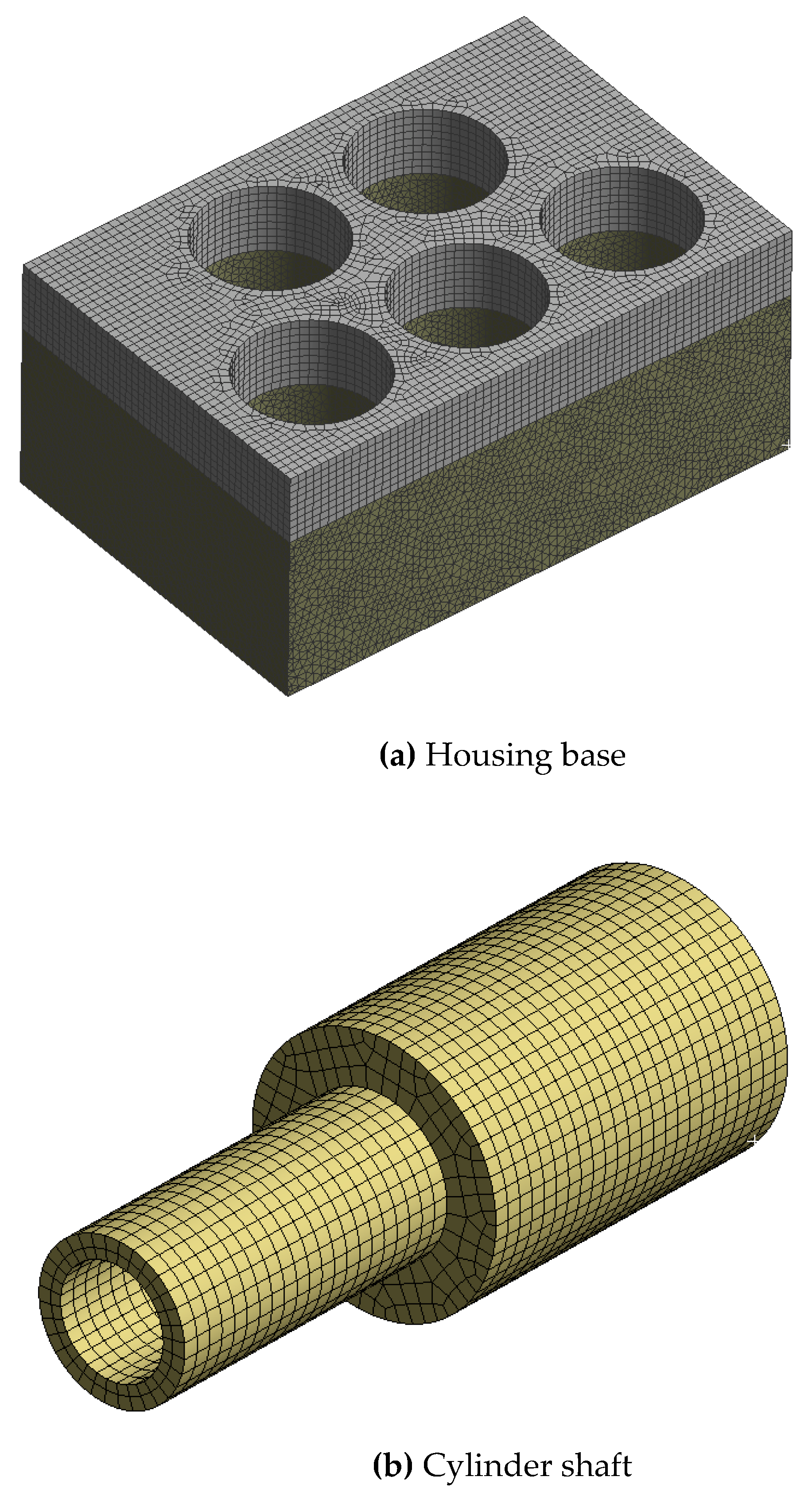
The key component models’ meshes were created using the ANSYS mesh module. The accuracy of the FEM simulation results is related to the resolution of the grid to some extent [34]. Numerous meshing strategies and comparisons were implemented. The target minimal mesh quality in the grid-independent investigation was selected as 0.5 based on the advised empirical value in the pertinent literature [33]. The element size of the grid-independent investigation was restricted to 0.1 mm to 7.0 mm according to the model size. As a result, the optimal element size was determined to be 3 mm, which indicates that a denser mesh has no impact on the outcomes of calculations. The proper meshing solution is shown in Figure 5. Since the springs are purchased according to the specification, their strength is not considered in this study. As shown in Figure 5a, the upper part of the housing base is outside the cylinder shaft stroke and not in contact with the hydraulic oil. Considering the size of the model, the element size of the grid is defined as 3.0 mm. In order to apply the hydraulic boundary condition more conveniently to the surface in contact with the inner fluid of the cylinder, the housing base model was divided into two parts and a shared topology was used. The upper part is divided into a hexahedral-type grid that can save calculation time; the lower part is divided into a tetrahedral-type grid and locally refined. The housing base model was divided into more than 640,000 mesh grids. Since the cylinder shaft has a multi-zone type cylindrical design, it was divided using a hexahedral-type mesh, as shown in Figure 5b. The total number of mesh grids here was over 6000. On the contrary, due to the irregular shape of the rope socket, the grid was divided using a tetrahedral-type mesh and local refinement was applied, as shown in Figure 5c. The total number of grids in the mesh of the rope socket was set as more than 20,000.
Considering the actual installation and operating conditions, the constraints and loads applied in simulation were defined as shown in Figure 6. The hydraulic pressure and rope tension, taking the safety factor required by the elevator industry into account, are defined as 5.16 MPa and 15,925 N, respectively. The static structural module of ANSYS was utilized for this structural stability simulation.

3.1.2. Results and Discussion

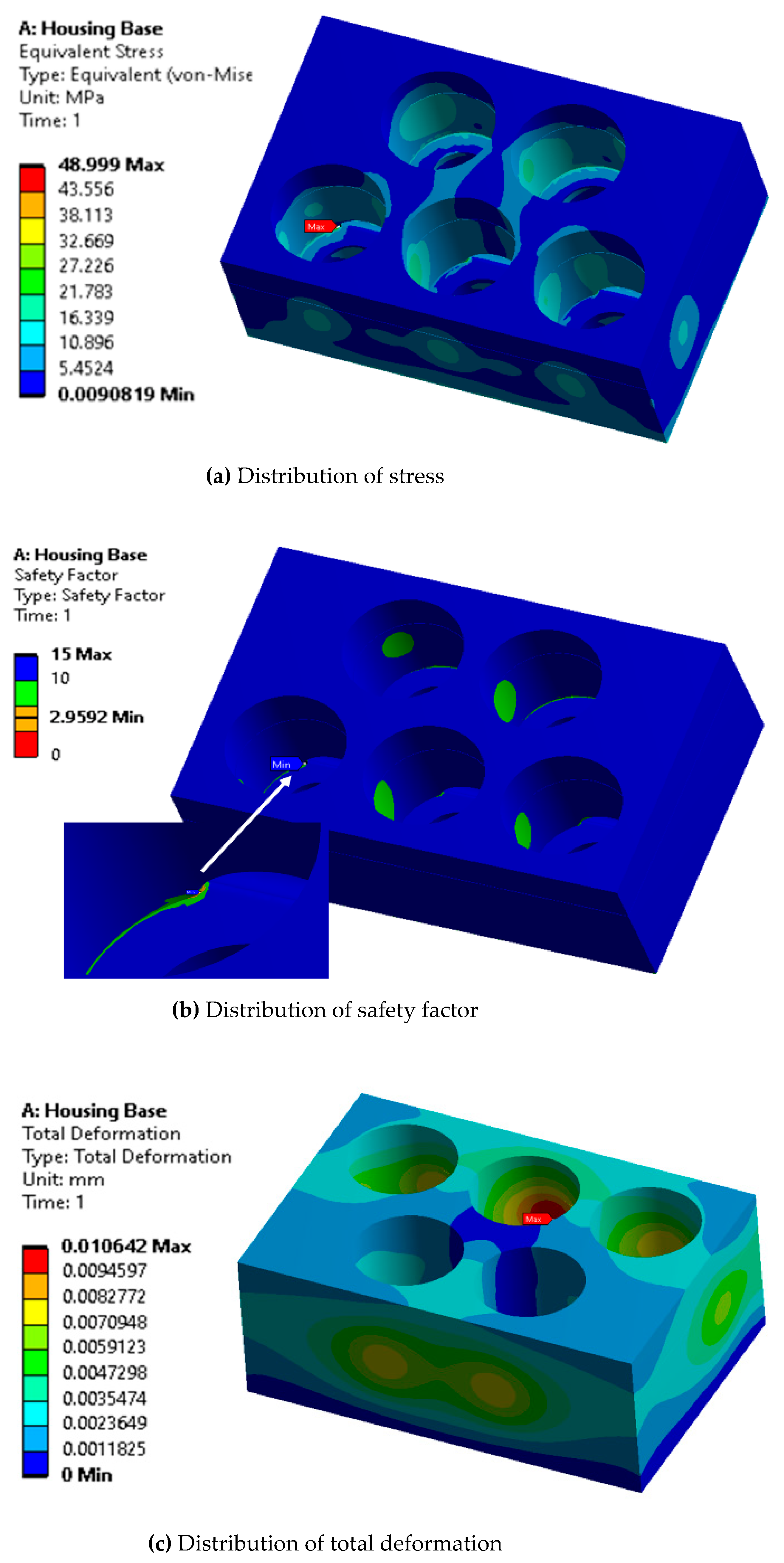
Figure 7a–c, respectively, show the simulation investigation results of the stress, deformation and safety factor distributions of the housing base. It can be seen that the maximum equivalent stress occurs at the junction between the hydraulic cylinder and the orifice of the intermediate pipeline. The maximum stress is about 49.0 MPa. It can be seen from the geometry of the housing base that the walls where the maximum stress appears are relatively thin and sharp, which leads to the stress concentration phenomenon under high pressures. The distribution of the safety factor can be obtained by using the yield strength of the material AL-6063 T5 used for the housing base and dividing it by the equivalent stress. As shown in Figure 7b, the minimum safety factor is about 3.0 and occurs at the same position as the maximum stress. The maximum deformation occurs in the inner wall of the cylinder and has a magnitude of 0.01 mm, which is negligible.
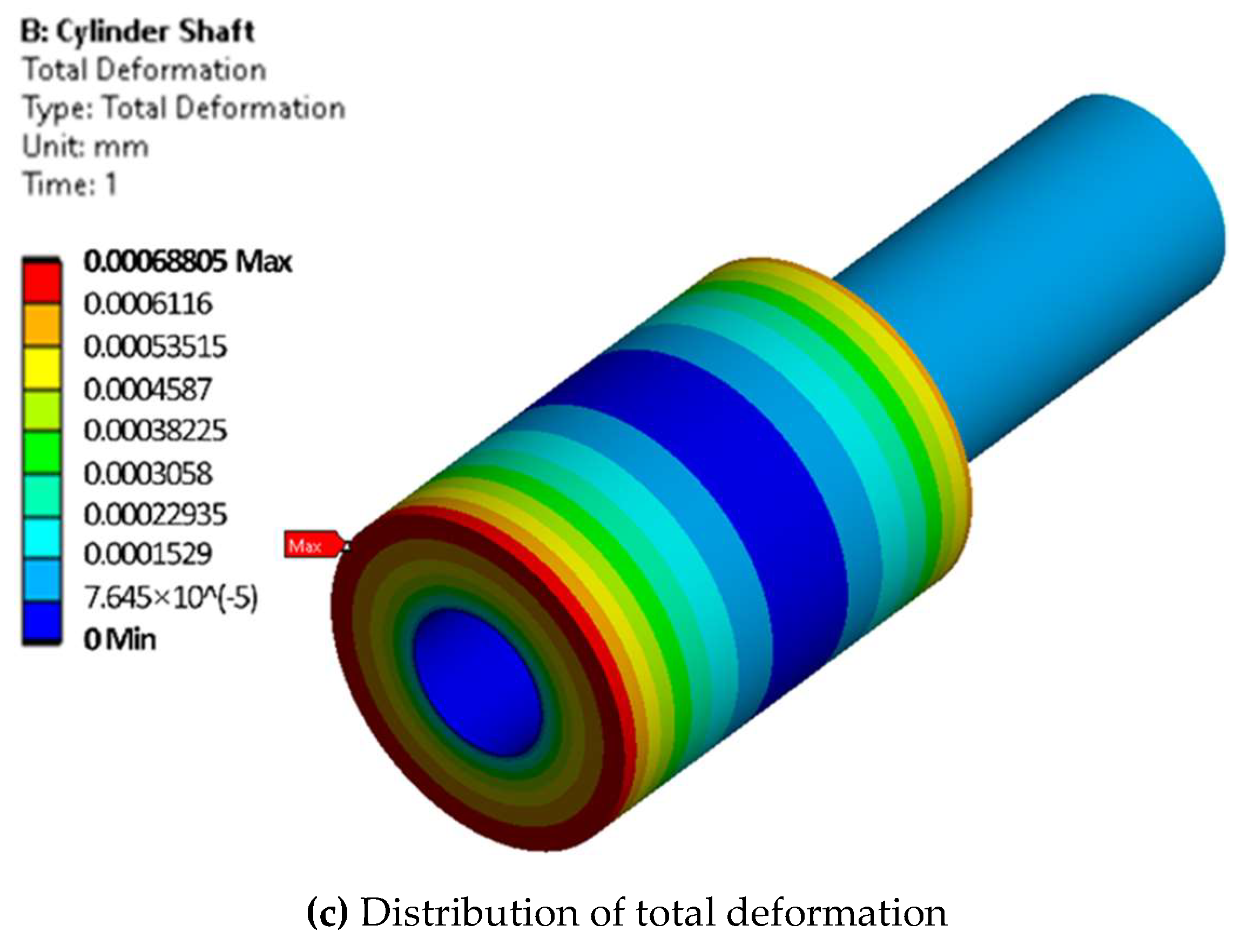
Figure 8 shows the simulation results of the stress, safety factor and deformation distribution in the cylinder shaft. In the cylinder shaft, the maximum stress of 21.3 MPa appears at the corner where the rope tension is applied. However, the minimum safety factor is above 15.0 and the maximum deformation is less than 6.9 × 10⁻⁴ mm, which is enough to prove the structural stability of the cylinder shaft.
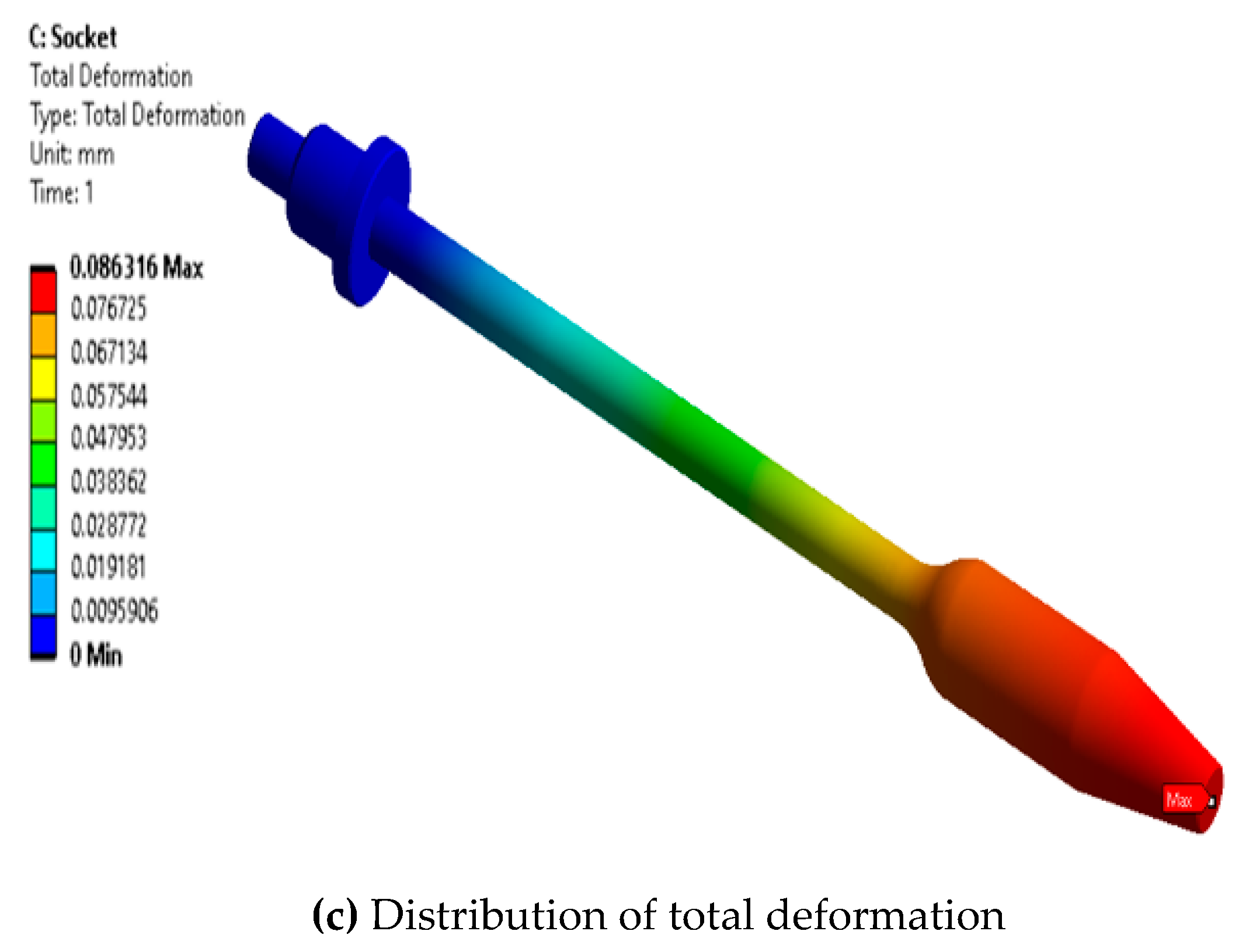
The rope socket is an important component that bears and transmits the rope tension. Figure 9 shows the structural simulation results of the rope socket. Similar to the cylinder shaft, in the rope socket, the maximum stress of 105.7 MPa also appears at the corner of the surface on the fixed boundary. The maximum deformation of 0.086 mm occurs on the surface where the load is applied which is far away from the fixed surface the deformation and decreases evenly along the axial direction of the rope. As shown in Figure 9c, the minimum safety factor is more than 2.3. In addition, the required safety factor has been considered in the load conditions at pre-processing of the simulation, thus it is proven that the safety and stability of the rope socket meets industrial requirements.

3.2. Experimental Validation

3.2.1. Experimental Investigation Methods

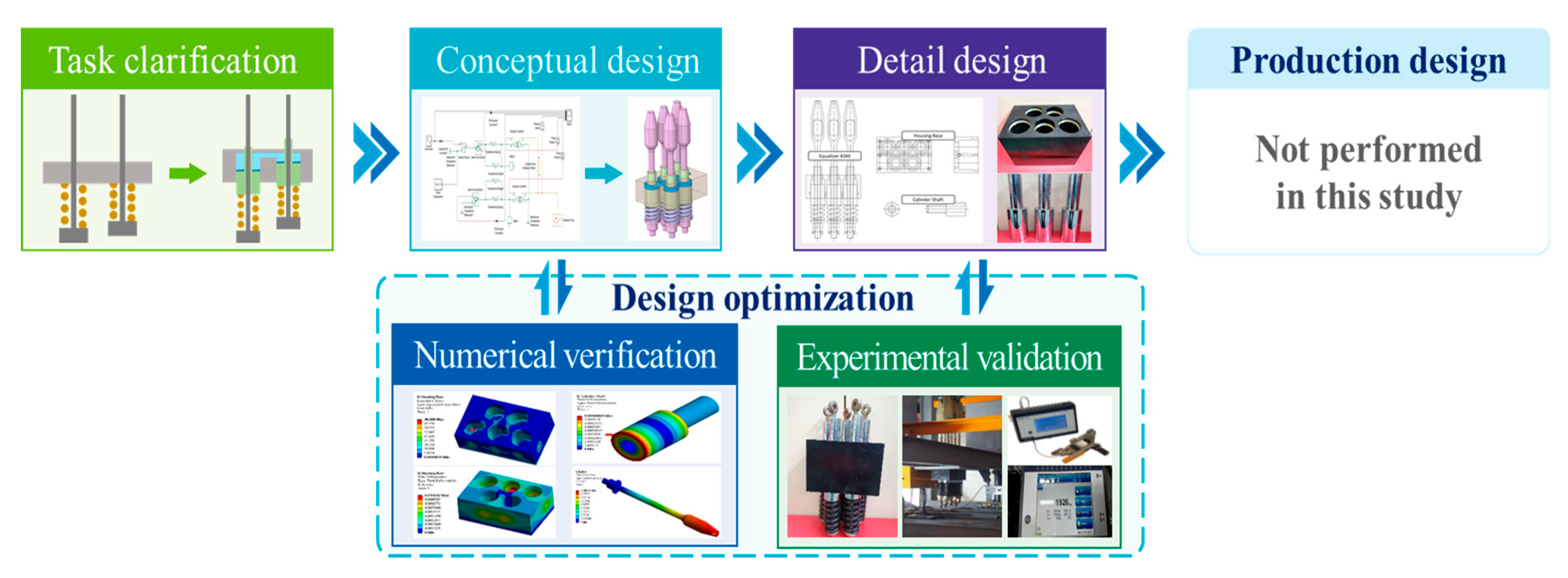
Distinct research objects typically require different approaches to system design and numerous generic design theories and methodologies have been proposed in the literature [35,36,37,38]. This study proposes a design procedure suitable for the NABE-RE system, as shown in Figure 10, based on the most representative German systematic design methodology. The goal of the task clarification phase is to identify the design’s requirements and objectives. The design goal for this study was to create a system that could equalize the tension between different ropes rather than balance the length of the ropes. In the conceptual design phase, a reasonable system model is put forth based on the design concept. Kinematic investigation is used to confirm the effectiveness of the equilibrating function in the NABE-RE. To determine the non-inferior geometric parameters, the suggested conceptual model was evaluated by a series of numerical validations. Then the non-inferior prototypes were produced and put into the experimental validation phase. By comparing the experimental results, the optimal systematic model can be summarized. The early design phases prior to the production design are the subject of this study. Numerical and experimental approaches are used to explore the design optimization.
In order to verify the automatic tension balancing function of the NABE-RE through experiments, core components that have been verified by the structural stability simulation were manufactured using a CMT (cutting mark trimming) machining center. Figure 11 shows the NABE-RE prototype used for performance testing (the internal structure and precise dimensions of the NABE-RE product cannot be disclosed due to the project confidentiality agreement).
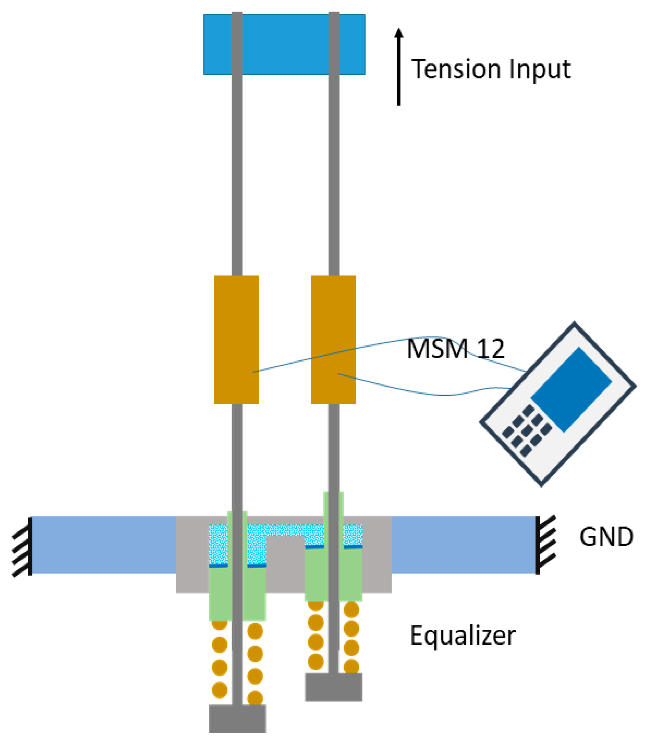
A performance test method was specified to observe and verify the characteristics of the automatic tension balancing function of the NABE-RE. Figure 12 shows the conceptual diagram of this NABE-RE performance test. The housing bases of the NABE-RE are fixed to the test bench, the rope sockets are rigidly connected to the ropes and tension monitoring sensors are installed on each rope. The tension data is gathered using the Henning MSM-12 equipment, as shown in Figure 13a. In order to observe the tension balancing among the ropes, a different tension is applied to each rope. The total tensions of 2228 kgf, 2205 kgf, 1926 kgf are applied to the top ends of the ropes using motor-driven pulley rotation. In order to facilitate the comparison, the conventional spring socket has also been tested (under total tension of 2105 kgf). Figure 13b shows the installation diagram for the performance test.
This study mainly uses the tension unbalance ratio to evaluate the automatic tension adjustment performance of the NABE-RE. The formula for calculating the unbalance ratio [25] is shown below:
U = X M a x X A v e X A v e · 100
Here, U represents the unbalance rate (%), X M a x represents the maximum deviation of measured tensions on each rope and X A v e represents the average value of measured tensions on all the ropes.

3.2.2. Results and Discussion

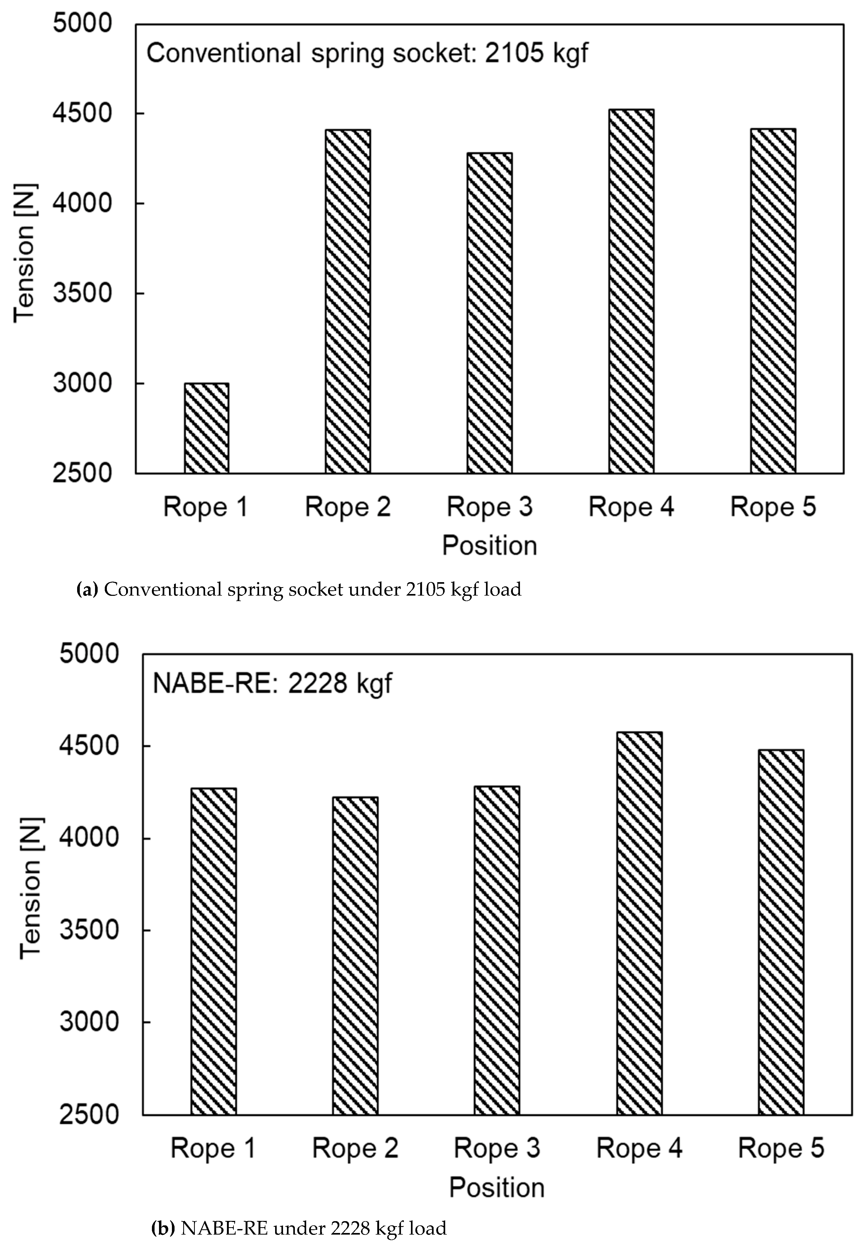
Figure 14 shows the results of the performance test. As shown in Figure 14a, the minimum tension on the conventional spring socket is 3001 N and the maximum tension is 4522 N. Thus, the maximum difference of tensions is 1521 N. Inserting the maximum deviation and average values into Equation (3), the tension unbalance rate of the five ropes is calculated to be about 27%. It was observed that the distribution of tensions between ropes was very uneven.
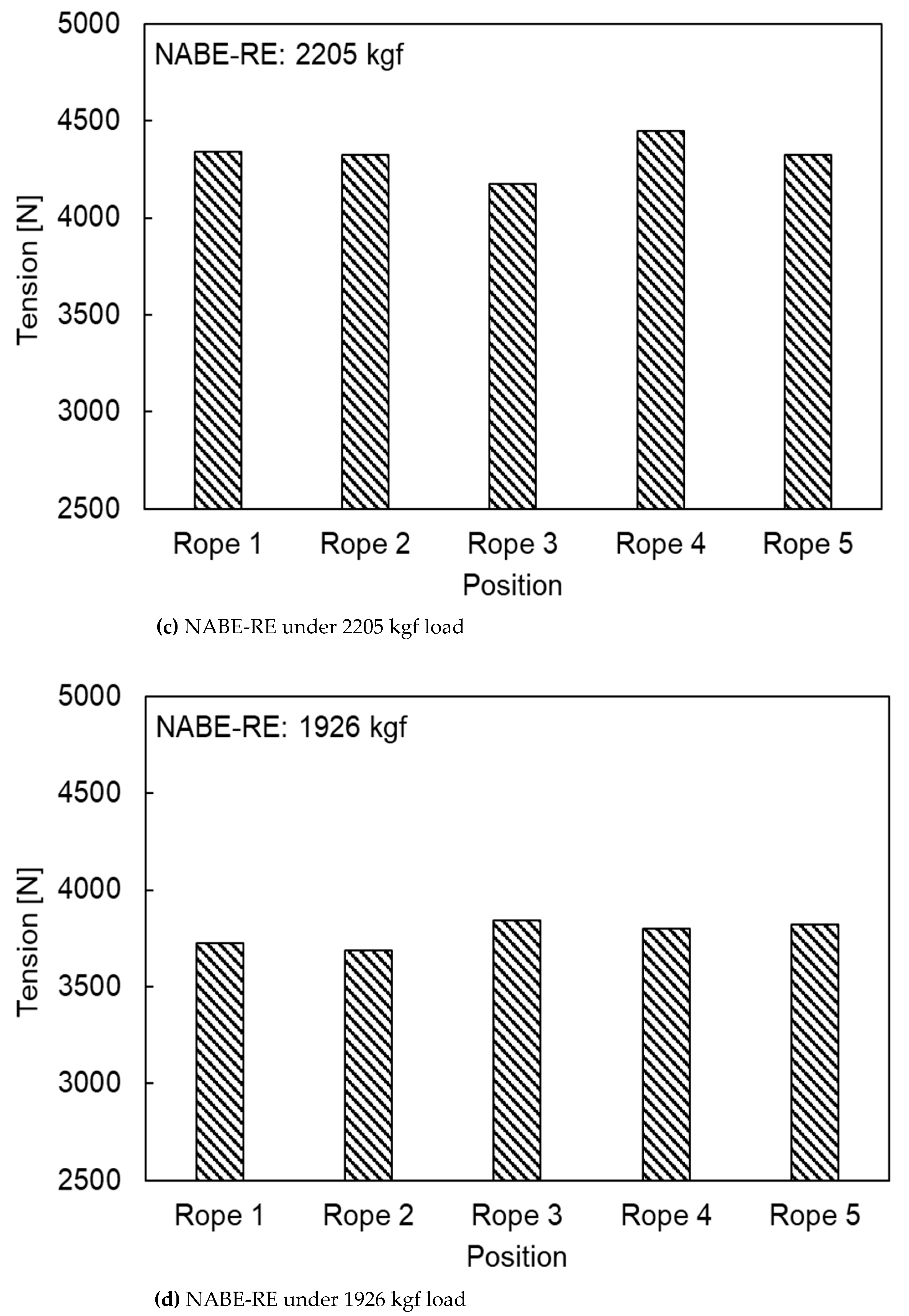
Figure 14b–d, respectively, show the balanced tension values on each rope under total tension of 2228 kgf, 2205 kgf 1926 kgf. It can be observed that the tension distribution on the five ropes is very uniform in the three test results.
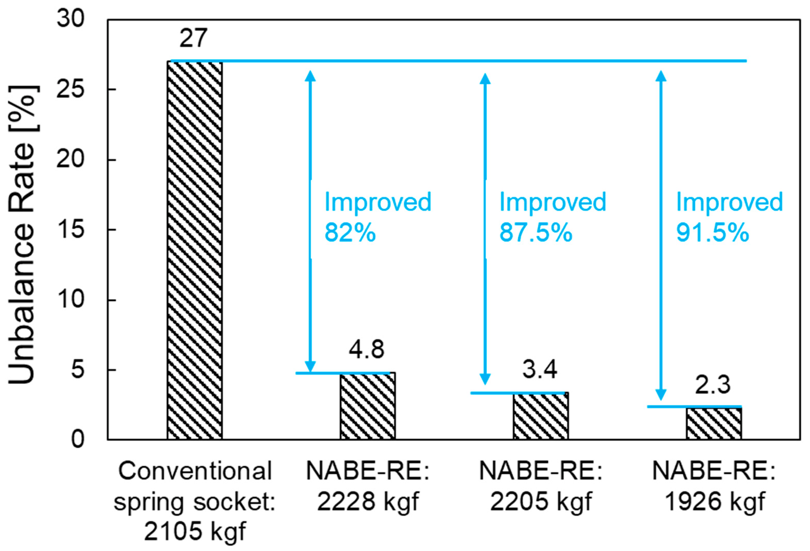
The comparison results of the unbalance rates of the four tension tests can be sorted as shown in Figure 15. It can be seen that the NABE-RE has an unbalance rate of 4.8% when the total tension is 2228 kgf; the smaller the total tension, the smaller the unbalance rate. When the total tension is 1926 kgf, the minimum unbalance rate of 2.3% is observed. It can be seen that, due to the use of the NABE-RE, the imbalance rate has been improved by up to 91.5% compared to that observed while using the traditional spring socket. In other words, the automatic tension balancing function of the NABE-RE can be verified by these performance test results.

4. Conclusions

In order to solve the existing problems of vibration, noise, uneven wear of key components and shortened life of the rope elevators due to the uneven distribution of rope tensions, this study presented the design of a Novel Automatic Balance Equipment for Rope-type Elevator (NABE-RE) based on Pascal’s principle and Hooke’s law. Numerical research methods were used to verify the rationality of the kinematics of the NABE-RE mechanism and the structural stability of its core components was observed using the finite element method. Finally, prototypes were made and the automatic tension balancing characteristics of the NABE-RE were verified through performance tests. The following conclusions can be drawn from this research:
(1)
The operating principle of the automatic tension balancing function of the NABE-RE mechanism was explained. To verify the kinematic validity of the mechanism, numerical investigation was performed using Simscape. From the kinematic simulation results, it can be seen that, when the cylinder shaft 1 is pushed a certain distance, the cylinder shaft 2 moves in the opposite direction with the same travel distance. This happens because the movement of shaft 1 increases the pressure inside the hydraulic system, which pushes cylinder shaft 2 to move in the opposite direction. The results of the high stiffness springs that showed the existence of the same force at both the input and output sides sufficiently demonstrate the automatic tension balancing function of the proposed mechanism. Based on the same kinematics, it can be determined that the mechanism can also be applied to elevator designs with multiple ropes.
(2)
The NABE-RE design with five ropes was selected to obtain an optimal structural stability for the design. The structural stability analyses of the core components (housing base, cylinder shaft and rope socket) based on the finite element method were performed. In the pre-processing of the simulation, the boundary conditions were set considering the actual load and the required safety factor. Different meshing methods were applied in the divided model with a shared topology to obtain a more efficient and accurate calculation. The results showed that the safety factor of all components was more than 2.0 and the maximum amount of deformation was also within the allowable value, which verifies that the structural stability of the proposed NABE-RE meets the design requirements.
(3)
A prototype of the numerically verified NABE-RE with five ropes was produced and the automatic tension balancing function was confirmed through the rope tension comparison experiments. When using the conventional spring socket, the maximum difference in rope tensions was 1521 N and the unbalance rate was more than 27%. When the NABE-RE was installed, a maximum difference between rope tensions of 353 N was measured under the total rope tension of 2228 kgf and the unbalance ratio was calculated to be about 4.8%. The minimum unbalance ratio of 2.3% was observed under the 1926 kgf loading condition. It was also observed that the smaller the total rope tension, the smaller the tension unbalance ratio between ropes. Therefore, it was confirmed that the proposed NABE-RE can reduce the difference of tensions between the different ropes to improve the unbalance ratio by more than 82% as compared to the conventional spring socket. The test results verified that the automatic tension balancing function of the proposed NABE-RE sufficiently meets the target of limiting the unbalance ratio to less than 10%.
(4)
The experimental results show that the unbalance rate of each rope in the elevator system significantly decreased by up to 91.5% after installing the NABE-RE. This fully validates the effectiveness of NABE-RE in balancing each rope’s tension and also proves that the proposed mechanism design meets the anticipated objective. However, the experiment in this study only evaluated the rope tension and was unable to confirm the dynamics and ride comfort of the elevator system installed by NABE-RE. Further research and product development are required for compatibility validation taking into account the entire elevator system and a number of NABE-RE products for different elevator models. The innovative design and research methodologies proposed in this study offer a crucial theoretical foundation for the technological advancement of the elevator industry and indicate the direction of future research to address the issues of elevator harshness and vibration durability. The design processes can be used to study a variety of mechanisms and offer effective design concepts for studying and creating new mechanisms.

Author Contributions

Conceptualization, Z.Q. and Y.W.; methodology, Z.Q.; software, Y.W.; validation, Z.Q. and S.-K.L.; formal analysis, Z.Q.; investigation, Y.W.; resources, J.C. and S.-K.L.; data curation, Z.Q. and Y.W.; writing—original draft preparation, Z.Q. and Y.W.; writing—review and editing, J.C. and S.-K.L.; visualization, Z.Q.; supervision, Y.W.; project administration, S.-K.L.; funding acquisition, Z.Q. and S.-K.L. All authors have read and agreed to the published version of the manuscript.

Funding

This work was supported by the Natural Science Foundation of Shandong Province under Grant ZR2022QE085 the Regional Leading Research Center of NRF and MOCIE (NRF-2019R1A5A8083201).

Conflicts of Interest

The authors declared that they have no conflict of interest to this work.

References

  1. Blokus, A.; Kołowrocki, K. Reliability and maintenance strategy for systems with aging-dependent components. Qual. Reliab. Eng. Int. 2019, 35, 2709–2731. [Google Scholar] [CrossRef]
  2. Chang, L.; Wei, S.; Xu, K.; Liu, J.; Li, T. An improved image denoising method based on contourlet transform and NeighShrink algorithm. Int. J. Comput. Appl. Technol. 2018, 57, 94. [Google Scholar] [CrossRef]
  3. Ryu, H.-M.; Kim, S.-Y.; Sul, S.-K.; Kwon, T.-S.; Kim, K.; Shim, Y.-S.; Seok, K.-R. Dynamic load simulator for high-speed elevator system. In Proceedings of the Power Conversion Conference-Osaka 2002 (Cat. No. 02TH8579), Osaka, Japan, 2–5 April 2002; Volume 2, pp. 885–889. [Google Scholar]
  4. Liu, S.; Sun, Y.; Ma, W.; Xie, F.; Jiang, X.; He, L.; Kang, Y. A New Signal Processing Method Based on Notch Filtering and Wavelet Denoising in Wire Rope Inspection. J. Nondestr. Eval. 2019, 38, 39. [Google Scholar] [CrossRef]
  5. Lee, Y.; Kim, T.S.; Cho, H.; Sung, D.K.; Choi, B.D. Performance analysis of an elevator system during up-peak. Math. Comput. Model. 2009, 49, 423–431. [Google Scholar] [CrossRef]
  6. Nguyen, X.T.; Miura, N.; Sone, A. Optimal design of control device to reduce elevator ropes responses against earthquake excitation using Genetic Algorithms. J. Adv. Mech. Des. Syst. Manuf. 2019, 13, JAMDSM0038. [Google Scholar] [CrossRef] [Green Version]
  7. Onur, Y. Theoretical investigation of rope strand subjected to axial tensile load. Int. Rev. Appl. Sci. Eng. 2019, 10, 1–5. [Google Scholar] [CrossRef]
  8. Peng, Q.; Jiang, A.; Yuan, H.; Huang, G.; He, S.; Li, S. Study on Theoretical Model and Test Method of Vertical Vibration of Elevator Traction System. Math. Probl. Eng. 2020, 2020, 8518024. [Google Scholar] [CrossRef] [Green Version]
  9. Boyko, A.; Volyanskaya, Y. Development of the gearless electric drive for the elevator lifting mechanism. East.-Eur. J. Enterp. Technol. 2018, 4, 72–80. [Google Scholar] [CrossRef] [Green Version]
  10. Onur, Y.A.; Aycan, O. Theoretical and experimental investigation of effects of failures on the tensile endurance of elevator ropes. Mater. Werkst. 2019, 50, 706–717. [Google Scholar] [CrossRef]
  11. Rostami, J.; Tse, P.; Yuan, M. Detection of broken wires in elevator wire ropes with ultrasonic guided waves and tone-burst wavelet. Struct. Health Monit. 2019, 19, 147592171985591. [Google Scholar] [CrossRef]
  12. Santo, D.R.; Balthazar, J.M.; Tusset, A.M.; Piccirilo, V.; Brasil, R.; Silveira, M. On nonlinear horizontal dynamics and vibrations control for high-speed elevators. J. Vibrat. Control. 2018, 24, 825–838. [Google Scholar] [CrossRef] [Green Version]
  13. Gerstenmeyer, S.; Peters, R. Safety distance control for multi-car lifts. Build. Serv. Eng. Res. Technol. 2016, 37, 730–754. [Google Scholar] [CrossRef]
  14. Taehoon, K.; Dongmin, L.; Minsu, C.; Hyunsu, L.; Myungdo, L.; Hunhee, C.; Kyung-In, K. Simulation-Based Lift Planning Model for the Lift Transfer Operation System. J. Constr. Eng. Manag. 2020, 146, 04020098. [Google Scholar]
  15. Van, L.D.; Lin, Y.B.; Wu, T.H.; Lin, Y.C. An Intelligent Elevator Development and Management System. IEEE Syst. J. 2020, 14, 3015–3026. [Google Scholar] [CrossRef]
  16. Wang, X.; Günay, S.; Lu, W. Seismic analysis of the rail-counterweight system in elevators considering the stiffness of rail brackets. Adv. Struct. Eng. 2020, 24, 1369433220974777. [Google Scholar] [CrossRef]
  17. Cao, G.; Cai, X.; Wang, N.; Peng, W.; Li, J. Dynamic Response of Parallel Hoisting System under Drive Deviation between Ropes with Time-Varying Length. Shock Vibrat. 2017, 2017, 6837697. [Google Scholar] [CrossRef] [Green Version]
  18. Kwon, D.; Kim, J.; Park, S.; Kwon, I.; DeVries, K.L.; Park, J. Damage sensing, mechanical and interfacial properties of resins suitable for new CFRP rope for elevator applications. Compos. Part B: Eng. 2019, 157, 259–265. [Google Scholar] [CrossRef]
  19. Yang, D.; Kim, K.; Kwak, M.; Lee, S. Dynamic modeling and experiments on the coupled vibrations of building and elevator ropes. J. Sound Vibrat. 2017, 390, 164–191. [Google Scholar] [CrossRef]
  20. Zhang, Q.; Hou, T.; Zhang, R.; Liu, J. Time-Varying Characteristics of the Longitudinal Vibration of a High-Speed Traction Elevator Lifting System. Int. J. Acoust. Vib. 2020, 25, 153–161. [Google Scholar] [CrossRef]
  21. Zhang, Q.; Yang, Y.; Hou, T.; Zhang, R. Dynamic analysis of high-speed traction elevator and traction car–rope time-varying system. Noise Vib. Worldw. 2019, 50, 37–45. [Google Scholar] [CrossRef]
  22. Zhang, Q.; Yang, Z.; Wang, C.; Yang, Y.; Zhang, R. Intelligent control of active shock absorber for high-speed elevator car. Proc. Inst. Mech. Eng. Part C 2019, 233, 3804–3815. [Google Scholar] [CrossRef]
  23. Zhao, Y.; Pan, J.; Huang, Z.; Miao, Y.; Jiang, J.; Wang, Z. Analysis of vibration monitoring data of an onshore wind turbine under different operational conditions. Eng. Struct. 2020, 205, 110071. [Google Scholar] [CrossRef]
  24. Nguyen, X.T.; Miura, N.; Sone, A. Analysis and control of vibration of ropes in a high-rise elevator under earthquake excitation. Earthq. Eng. Eng. Vib. 2019, 18, 447–460. [Google Scholar] [CrossRef]
  25. Kim, D.; Kim, G. A Study on the Development of an Elevator Rope Tension Automatic Equalizer. J. Korean Soc. Manuf. Process Eng. 2020, 19, 60–66. [Google Scholar] [CrossRef]
  26. Qin, Z.; Wu, Y.; Huang, A.; Lyu, S.; Sutherland, J. Theoretical Design of a Novel Vibration Energy Absorbing Mechanism for Cables. Appl. Sci. 2020, 10, 5309. [Google Scholar] [CrossRef]
  27. Fujiwara, E.; Cordeiro, C. Model-Based Design and Simulation of Paraxial Ray Optics Systems. Appl. Sci. 2020, 10, 8278. [Google Scholar] [CrossRef]
  28. Kulshrestha, A.; Mahela, O.; Gupta, M.; Khan, B.; Haes Alhelou, H.; Siano, P. Hybridization of Stockwell Transform and Wigner Distribution Function to Design Transmission Line Protection Scheme. Appl. Sci. 2020, 10, 7985. [Google Scholar] [CrossRef]
  29. Qin, Z.; Zhang, Q.; Wu, Y.T.; Eizad, A.; Lyu, S.K. Experimentally Validated Geometry Modification Simulation for Improving Noise Performance of CVT Gearbox for Vehicles. Int. J. Precis. Eng. Manuf. 2019, 20, 1969–1977. [Google Scholar] [CrossRef]
  30. Qin, Z.; Wu, Y.T.; Eizad, A.; Lee, K.H.; Lyu, S.K. Design and evaluation of two-stage planetary gearbox for special-purpose industrial machinery. J. Mech. Sci. Technol. 2019, 33, 5943–5950. [Google Scholar] [CrossRef]
  31. Qin, Z.; Wu, Y.T.; Eizad, A.; Jeon, N.S.; Kim, D.S.; Lyu, S.K. A Study on Simulation Based Validation of Optimized Design of High Precision Rotating Unit for Processing Machinery. Int. J. Precis Eng. Manuf. 2019, 20, 1601–1609. [Google Scholar] [CrossRef]
  32. Qin, Z.; Tang, X.; Wu, Y.-T.; Lyu, S.-K. Advancement of Tidal Current Generation Technology in Recent Years: A Review. Energies 2022, 15, 8042. [Google Scholar] [CrossRef]
  33. Qin, Z.; Son, H.I.; Lyu, S.K. Design of anti-vibration mounting for 140A class alternator for vehicles. J. Mech. Sci. Technol. 2018, 32, 5233–5239. [Google Scholar] [CrossRef]
  34. Corte, W.; Van Meirvenne, K.; Boel, V.; Taerwe, L. Design of Anchorage Zones of Pretensioned Concrete Girders: A Comparison of Nonlinear 3D FEM Results with Measurements on a Full Scale Beam. Appl. Sci. 2020, 10, 8221. [Google Scholar] [CrossRef]
  35. Fiorineschi, L.; Papini, S.; Pugi, L.; Rindi, A.; Rotini, F. Systematic design of a new gearbox for concrete mixers. J. Eng. Des. Technol. 2020, 18, 2017–2042. [Google Scholar] [CrossRef]
  36. Zheng, P.; Lin, T.J.; Chen, C.H.; Xu, X. A systematic design approach for service innovation of smart product-service systems. J. Clean. Prod. 2018, 201, 657–667. [Google Scholar] [CrossRef]
  37. Bakker, T.; Bontsema, J.; Müller, J. Systematic design of an autonomous platform for robotic weeding. J. Terramech. 2010, 47, 63–73. [Google Scholar] [CrossRef]
  38. Rotini, F.; Becattini, N.; Borgianni, Y.; Fiorineschi, L. Editorial for the Special Issue “Requirements in Design Processes: Open Issues, Relevance and Implications”. Appl. Sci. 2022, 12, 10109. [Google Scholar] [CrossRef]
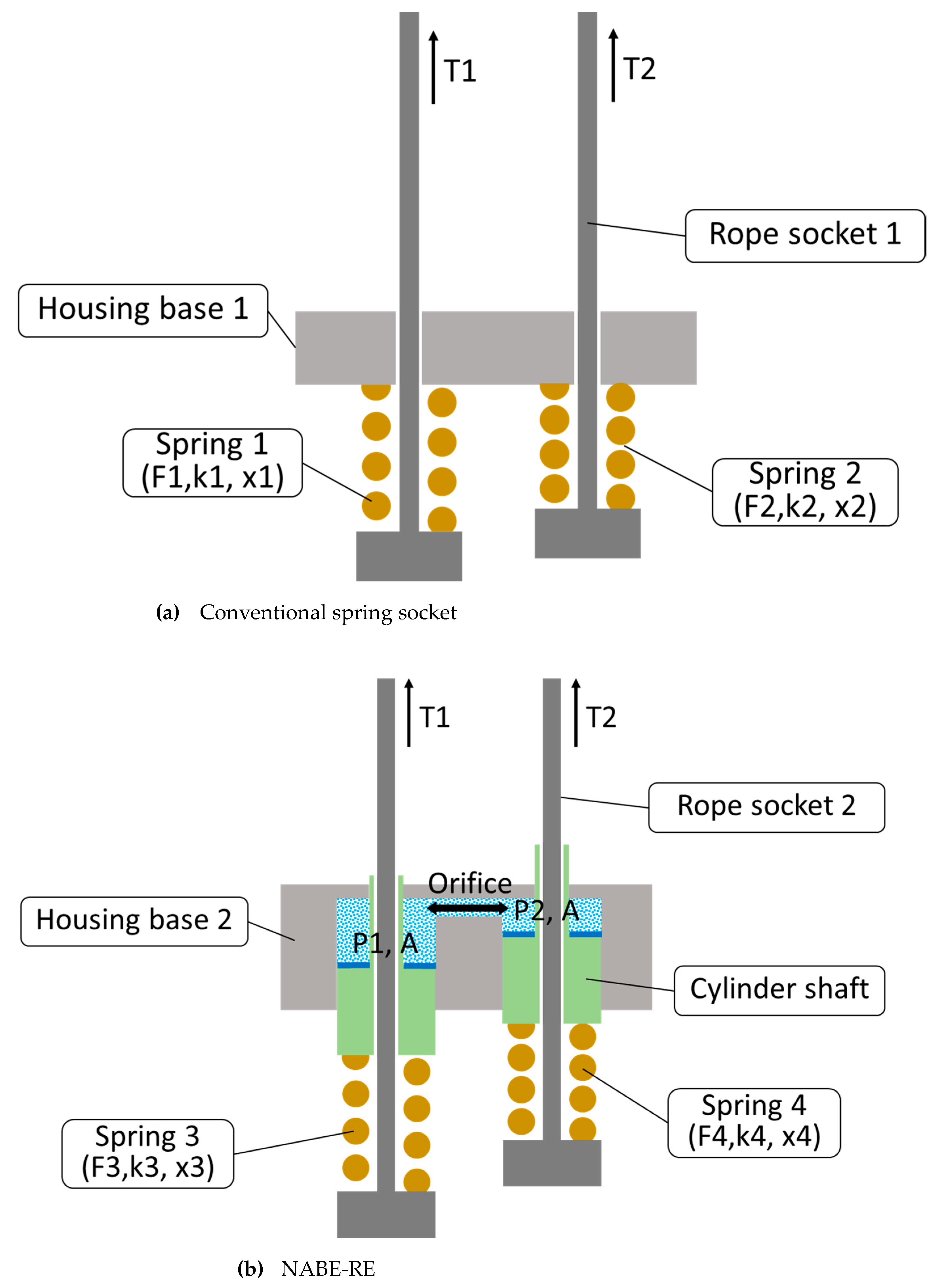
Figure 1. Schematic diagrams of the conventional spring socket and the NABE-RE.
Machines 10 01180 g001
Figure 2. Simscape model for the kinematic analysis of NABE-RE.
Machines 10 01180 g002
Figure 3. Results of the Simscape simulation.
Machines 10 01180 g003aMachines 10 01180 g003bMachines 10 01180 g003c
Figure 4. Three-dimensional modeling of the NABE-RE system.
Machines 10 01180 g004
Figure 5. Meshing of the important components.
Machines 10 01180 g005aMachines 10 01180 g005b
Figure 6. Boundary conditions for the structural analysis.
Machines 10 01180 g006aMachines 10 01180 g006b
Figure 7. Analysis results for the housing base.
Machines 10 01180 g007
Figure 8. Analysis results for the cylinder shaft.
Machines 10 01180 g008aMachines 10 01180 g008b
Figure 9. Analysis results for the rope socket.
Machines 10 01180 g009aMachines 10 01180 g009b
Figure 10. Systematic design process considered in this study.
Machines 10 01180 g010
Figure 11. Photograph of the performance test prototype.
Machines 10 01180 g011
Figure 12. Schematic diagram of the performance test.
Machines 10 01180 g012
Figure 13. The test equipment and field installation used for the performance test.
Machines 10 01180 g013aMachines 10 01180 g013b
Figure 14. Experimental results of the tension performance test.
Machines 10 01180 g014aMachines 10 01180 g014b
Figure 15. Results comparison of the unbalance rate under different conditions.
Machines 10 01180 g015
Table 1. The default simulation parameters.
ParametersValue
Elastic coefficient of the high stiffness spring [kgf/mm]48
Structural damping of the high stiffness spring [N/(m/s)]0.02
Preload value of the high stiffness spring [mm]13.0
Area of the hydraulic piston presented to the hydraulic pressure [mm2]1235.3
Initial position of the two hydraulic cylinder shafts [mm]15.0
Total stroke of the two cylinders [mm]30.0
Load on each rope [kgf]260
Density of the hydraulic oil [kg/m3]844.4
Viscosity of the hydraulic oil [cSt]15.9869
Table 2. Mechanical properties of the materials used.
Part NameMaterialYield StrengthUltimate StrengthPoisson’s RatioDensity
Housing BaseAL-6063 T5145 MPa185 MPa0.332770 kg/m3
Cylinder ShaftS45C580 MPa680 MPa0.297850 kg/m3
Rope socketSS41245 MPa510 MPa0.307850 kg/m3
Publisher’s Note: MDPI stays neutral with regard to jurisdictional claims in published maps and institutional affiliations.