Article

Circular Economy in Practice: Building a Simple Greenhouse from Recycled Plastic

1
Program in Interdisciplinary Studies, National Sun Yat-sen University, Kaohsiung 80424, Taiwan
2
Outfitting Design Section of Design Department, China Ship Building Corporation, Kaohsiung 81234, Taiwan
3
Department of Vehicle Engineering, National Taipei University of Technology, Taipei 10608, Taiwan
4
Department of Mechanical and Electro-Mechanical Engineering, National Ilan University, Yilan 26047, Taiwan
*
Author to whom correspondence should be addressed.
Machines 2022, 10(12), 1207; https://doi.org/10.3390/machines10121207
Submission received: 19 October 2022 / Revised: 9 December 2022 / Accepted: 11 December 2022 / Published: 13 December 2022

Abstract

:
Reusing materials in multiple cycles is the key to achieving a circular economy. Recycled composite rods made from the mix of discarded fishing nets and car bumpers are proposed as a promising building material to construct a greenhouse. However, the mechanical properties of the recycled composite rods are different from their original materials, thus the feasibility for use in products must be verified through design, analysis, and implementation processes. In this study, we investigate the feasibility of recycling composite material through the force generated by the simulated eleven level wind blowing to the greenhouse. Static force analysis (axial tensile force, X-axis bending moment, and Y-axis bending moment) at the joints between rods showed that the bolt hole of the fasteners would not break and bring safety issues. Dynamic force analysis results indicate that, under vibration caused by an earthquake or operation of the exhaust fan, there would not be a sufficient resonance at the joint to cause the greenhouse to collapse. We demonstrate that the construction of a greenhouse covering an area of 60 m2 is feasible.

1. Introduction

Environmental protection has become increasingly important, and people have been seeking new applications for waste that are difficult to decompose naturally. Therefore, each product is thoughtfully designed so that all materials and manufacturing waste can be an input to another process for a circular economy [1,2,3,4,5,6]. In the field of construction, researchers have proposed using recycling waste products for construction materials [7,8,9,10,11,12,13,14,15,16], for example, particles (MG) of construction waste mixture into concrete [8], discarded reeds and cork blocks into concrete [9], waste coffee bean shells for building components [10], waste cardboard and wood as sound-absorbing materials [11], mixed recycled polyethylene plastic with recycled wood, glass fiber, mineral wool, gypsum, and soapstone to make building bricks [12], mixed recycled PET, recycled concrete, and broken bricks to make pavement applications [13], recovered scraps of polyethylene with different densities for building components [14], rubber scraps for create a rubber drainage layer [15], and PET plastic bottles for thermal insulation panels [16].
In addition, numerous industrial products contain plastics, which are discarded after use [17,18]. The waste plastic is a potential building material. However, the strength of plastic materials in all aspects is lower than that of traditional building materials, e.g., steel channels and cement. When using waste plastics as building materials, the buildings constructed need to be light and not have excessive loads. Greenhouses are lightweight buildings with little load and are widely used all over the world. Mistriotis and Briassoulis [19] used computational fluid dynamics to optimize the design of greenhouse domes. Ren et al. [20] used the finite element method (FEM) to analyze the properties and stability of a large-span plastic greenhouse. Wang et al. [21] studied the static properties and failure mechanisms of greenhouses. Hur and Kwon [22] conducted a complete FEM of the exterior and structure of the greenhouse and discussed the impact of strong winds on the structural joints. In addition, studies have focused on mechanical analysis and sustainable design of fasteners for joining building materials. Ataei et al. [23] proposed a sustainable high-strength steel flush-end plate beam-column composite joint with deconstructable bolted shear connections and obtained a stress–strain diagram and a slip curve through mechanical experiments. Xiao et al. [24] carried out structural design and then performed pressure and shear tests on the joints required for recycled aggregate concrete. Jin et al. [25] used FEM to determine the stress state of the connection point between a square concrete-filled steel tubular (CFST) K-joint and the concrete. Choi et al. [26] designed a set of steel pipe joints for greenhouses and performed assembly and pressure bearing tests on each joint.
It has been proposed that discarded fish nets and car bumpers can be made into composite rods, which can be used as building materials for greenhouses [27]. The fishing net is usually made of polyamide (PA) and polyethylene terephthalate (PET), and car bumpers are made of fiber-reinforced plastic (FRP). Researchers mixed the recycled plastic material and granulated it, which became the formula of the rod after reconciling the material. The material properties differ much among different types of plastics. Although the composite rod is promising for new applications, such a novel material still lacks mechanical analysis as a building material for greenhouses. Most importantly, it is required to verify whether the recycled materials can be used to safely build a greenhouse through design, static force, dynamic vibration simulation analysis, and implementation. Therefore, this study follows three steps to fabricate a greenhouse from recycled composite materials: (1) for the force analysis of the greenhouse, the rod bending state forced by the wind is analyzed for static force. The vibration action caused by earthquake and fan is considered for dynamic behavior in this paper. (2) Recycled material parts usually contain multiple material properties, which makes the product formed in special dimensions. Therefore, we design the fastener independently. (3) Using recycled plastic material to build a simple greenhouse to achieve a circular economy is examined.
The subsequent sections of this paper are as follows. Section 2 and Section 3 present material, rod, fastener, and greenhouse design information. Section 4 describes the static force and dynamic force analysis, as well as on-site construction. Section 5 discusses the feasibility of using recycling plastic composites for simple greenhouse design. Finally, Section 6 summarizes this study and indicates future research directions.

2. Materials

In order to manufacture stronger building materials, relatively high-strength plastics are selected as raw materials. The rods for the greenhouse were made of recycled composite plastics obtained from discarded fishing nets (i.e., PA, PET) and car bumpers (i.e., FRP), which are not sold on the market. The manufacturer mixed the recycled plastic material and granulated it, which become the formula for the rod after reconciling the material. The material properties of the rod material are shown in Table 1. The greenhouse design follows the safety standards published by the National Architecture Association [28], and it must be able to withstand a force 11 wind (corresponding to a wind speed of 33 m/s), equivalent to a moderate typhoon. Because the mechanical strength of the rod is lower than the hollow galvanized steel tubes that are available in the market, the dimensions must be carefully chosen to achieve safety in use.
After considering manufacturing feasibility and adjusting the manufacturing parameters, the material of the rod will be extruded through the customized mold. The rod shape was chosen to be a hollow square with an internal support structure, as shown in Figure 1a. The outer dimension of the rod was 50 mm × 50 mm, and the cross supports had a thickness of 5 mm. A photograph of the as-manufactured product is shown in Figure 1b.

3. Methods

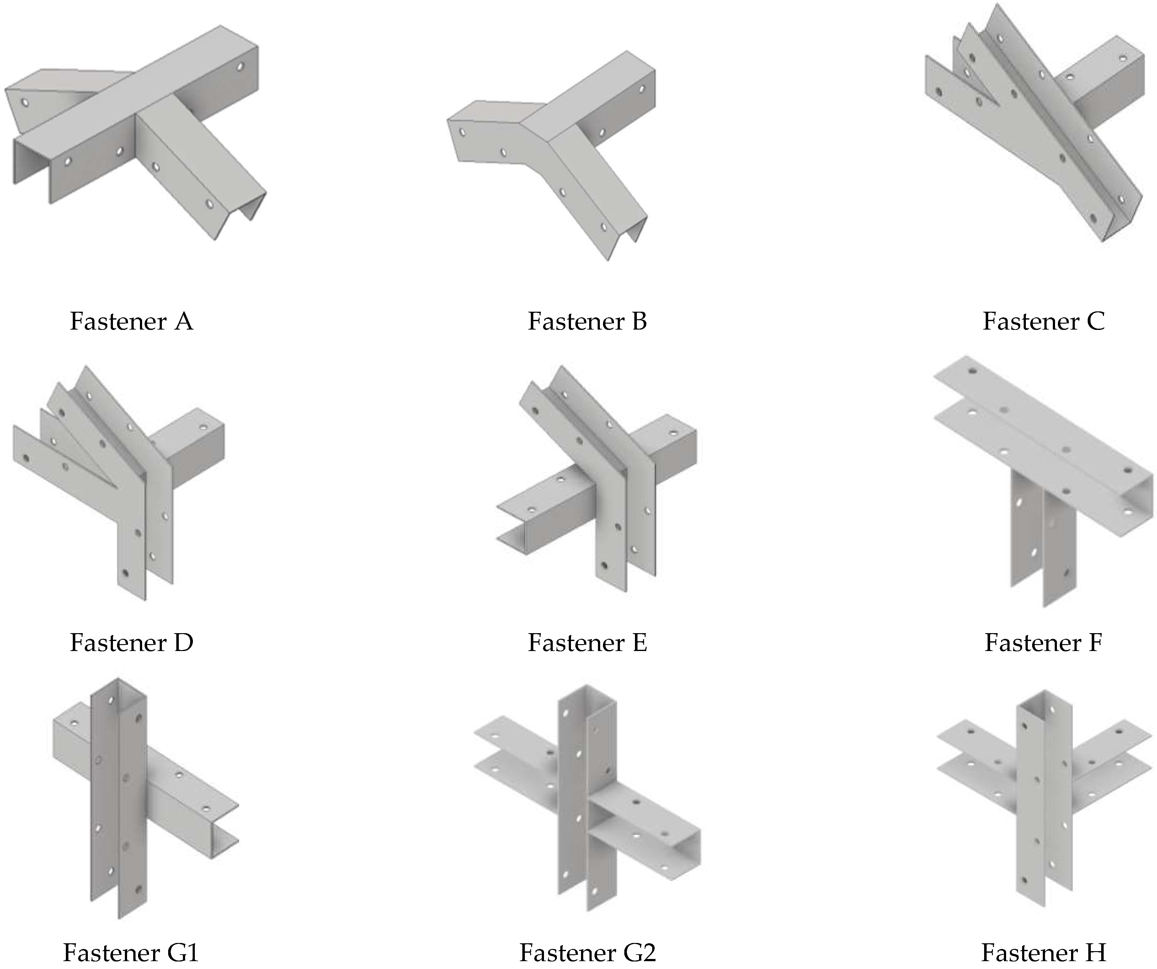
The square shape of the rod means that square-shaped fasteners are required, instead of the typically used fasteners for round rods. The newly designed fasteners are numbered from A to I, as shown in Figure 2. The dimension information is shown in Figure S1 of Supplementary, and the corresponding positions in the greenhouse structure are shown in Figure 3. The fastener material was stainless steel (SUS 304) with a thickness of 2 mm, which is easy to manufacture, low in cost, and has sufficient mechanical strength (tensile strength is 505 MPa; yield strength is 215 MPa; and Young’s modulus is 193 GPa). The properties of the bolts used, and their torque settings, are ignored in this analysis. The process of developing the simple greenhouse is listed as follows:
Step #1
Design the geometries of rods and fasteners.
Step #2
Run static stress analyses.
Step #3
Check is the results fit the safety requirements or not. If the safety requirements are not satisfied, return to Step #1.
Step #4
Run dynamic force analyses.
Step #5
Check if the results fit safety requirements or not. If the safety requirements are not satisfied, return to Step #1.
Step #6
Build the simple greenhouse.
Force analysis of the joint between the rod and the fastener was performed using the Inventor CAD software package. The purpose of this was to quickly identify the areas of the greenhouse that would be most likely to fail during use. The material properties, force types, force values, and boundary conditions of all objects must be set before analysis. The results of static force analysis were compared with the von Mises stress to determine whether the rods and fasteners would be damaged. The safety of the structure was judged by calculating the safety factor, which is the ratio of ultimate stress to allowable stress. Generally, the safety factor should be equal to or greater than one [29]. Then, dynamic force analysis was used to judge whether the vibration frequency generated by external force will cause resonance phenomenon and lead to structural damage. The following sections will introduce the static force analysis, dynamic force analysis, and on-site construction of the greenhouse.

4. Results

4.1. Static Force Analysis

According to the regulations made by the National Architecture Association [28], a greenhouse must be able to withstand a force 11 wind, and it should not collapse even if it is deformed. The simulation of the static stress analysis of the simple greenhouse under the force 11 wind load was carried out by SAP2000 software, and the corresponding setup is shown in Figure 4a. For force 11 wind, the equivalent wind speed is 33 m/s. Thus, two directions of force-11 wind, i.e., along the x-axis and y-axis, are applied, respectively, to the simple greenhouse. The locations where the maximum deflections along the x-axis, y-axis, and z-axis occur under the force 11 wind load are shown in Figure 4b. Furthermore, the worst case of the axial tensile force, x-axis bending moment, and y-axis bending moment of each fastener were summarized in Table 2.
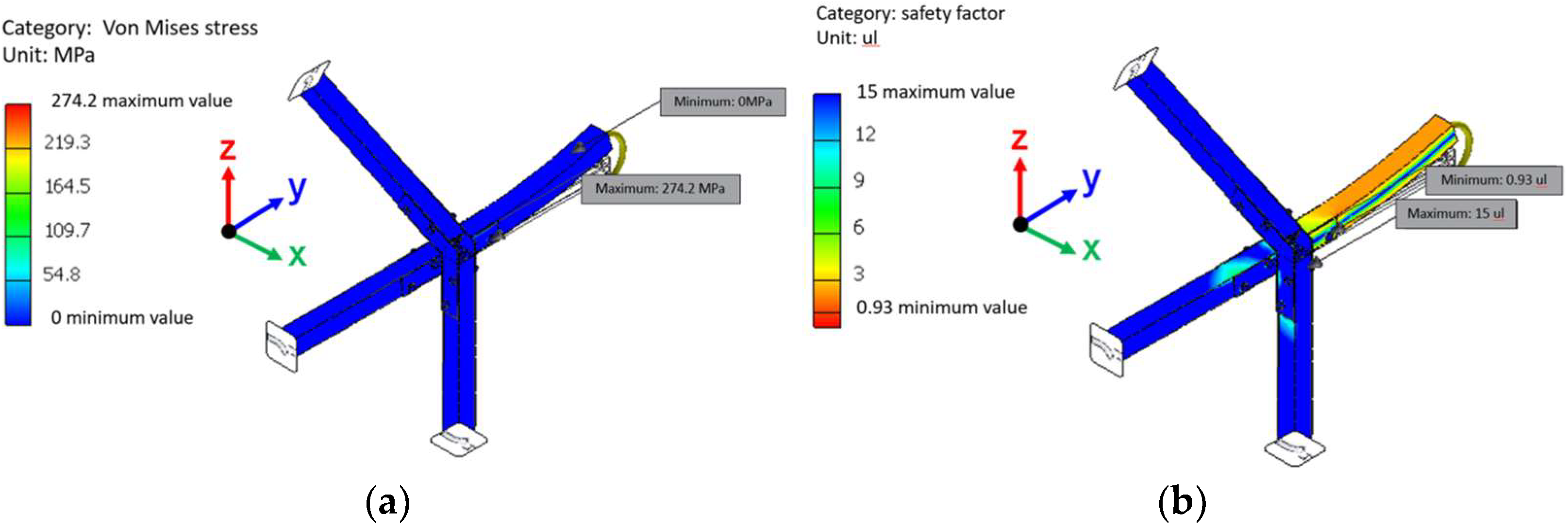
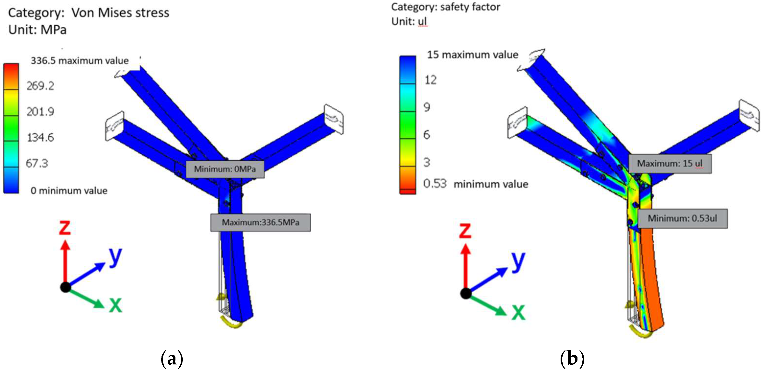
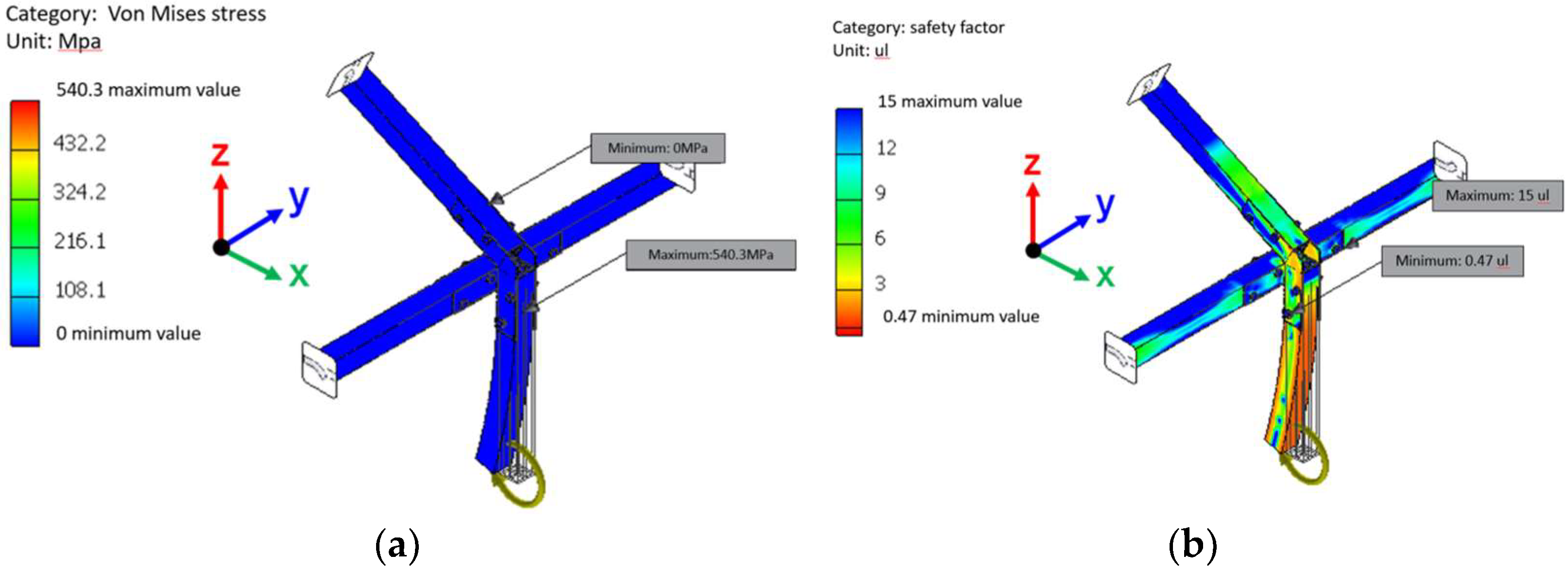
The von Mises stress of each fastener was calculated by the Inventor software using the values in Table 2, and the results are shown in Table 3. The detailed analysis results are shown in Figures S2–S19 of Supplementary. In addition, the calculated safety factors for each fastener are summarized in Table 4. It can be seen that the safety factor of all fasteners under axial tension force exceeds 1, which meets the safety conditions. However, the safety factors of fastener B and E under the X-axis bending moment are only 0.71 and 0.93, respectively; furthermore, the respective safety factors of fasteners D, E, and F under the y-axis bending moment are only 0.53, 0.47, and 0.94. Referring to the analysis results shown in Figure 5, Figure 6, Figure 7, Figure 8 and Figure 9, it was found that the positions where the safety factor is less than 1 all fall on the bolt at the junction of the rod and the fastener. The safety factor is calculated on the assembly datum, not just on the fixed point. This means that the bolt holes in the fastener would deform, but this deformation will not affect the overall safety of the fastener.

4.2. Dynamic Force Analysis

In order to determine whether any fasteners are subjected to resonance, which could potentially cause structural damage under the influence of a dynamic external force, the first 15 orders of resonant frequencies of all fasteners were obtained through analysis utilizing the Inventor software. The selected external vibrations were from earthquakes, and an exhaust fan was erected on the greenhouse walls to enhance air convection. The resonant frequencies of all fasteners are shown in Table 4, and the detailed information is given in Supplementary Materials. The results show that the first six orders of all fasteners were rigid body displacements without fixed constraints, so the obtained frequency is zero for earthquakes in Taiwan, and the frequency falls within 0.8–3 Hz. If this frequency range is expanded to 0.5–4 Hz for an enhanced safety margin, it can be seen, from Table 4, that the vibration generated by the earthquake will not resonate with any of the fasteners to cause structural damage to the greenhouse. From the exhaust fan, which operates at a low operating frequency (125.60 Hz) or a high operating frequency (167.46 Hz), it can be found that the high operating frequency is somewhat close to the 7th order resonant frequency of fasteners B and D, as well as the 8th order resonant frequency of fastener D. However, the difference of the resonant frequencies between fasteners B and D is 7%. Besides, it can be seen from Figure 3 that the two fasteners, i.e., fasteners B and D, have no direct contact rod with the exhaust fan to cause resonance.

4.3. On-Site Construction of the Greenhouse

The goal of the on-site construction was to construct a greenhouse covering an area of 60 m2. The sequence of the construction process was: (1) boundary setting and foundation trench excavation, (2) foundation block construction, (3) assembly of the greenhouse walls by connecting the rods with fasteners, (4) connecting the cement foundation blocks to the post rod of each wall with fastener I, (5) securely fixing the bead groove which is used to cover the surface of the greenhouse and each rod, (6) backfilling and irrigating the foundation trench, (7) installing insect net and plastic agricultural film, (8) installing doors and exhaust fans, (9) electricity and water supply configuration, and (10) operation testing of exhaust fans. As opposed to typical greenhouse construction, most of the rods are assembled on the ground first. Therefore, the total construction time is relatively short, and the construction process is much simpler. Figure 10 shows the assembly of all fasteners and rods. Figure 11 shows a photograph of the completed greenhouse.

5. Discussion

The construction industry has great potential to develop a circular economy by recycling waste materials into building materials. Because plastic waste accounts for a large proportion of construction waste, prioritizing the use of recycled building materials can not only effectively reduce plastic waste, but also reduce the extraction of raw materials. However, the mechanical properties of recycled building materials must be carefully evaluated to ensure building safety. In this study, the tensile strength of the recycled plastic material was measured to be 55.1 MPa, according to the same experimental method as Sormunen et al. [12]. The next step was to confirm that the overall greenhouse design was structurally safe. Many research teams have achieved this through the use of CAD software. For example, Jin et al. [25] used FEM to analyze the deformation degree and maximum load value of the joints of the components. In this study, Inventor was used to analyze the stress of the fasteners at the joint with the rods, and then it was used obtain the axial tension, x-axis bending moment, and y-axis bending moment that each fastener must bear. These data were compared against the values specified in the regulations by the Taiwan Agriculture and Food Administration [28]. Then, when the safety of the partial assembly of the building was established, the final safety assessment was made on the completed greenhouse. Hur and Kwon [22] simulated the vibration of the joints caused by wind forces. Their approach was followed in this study to analyze the dynamic forces encountered in the use of greenhouses. The analysis simulates earthquake and exhaust fan vibration to assess whether the designed greenhouse structure would pose a hazard under both types of vibration. Finally, when these safety assessments were completed, on-site construction was undertaken. In agreement with the findings of Perera et al. [13] and Laria et al. [14], the additional mechanical property testing and force analysis can accelerate the speed of future commercialization.

6. Conclusions

The goal of a circular economy is that all materials can always be recycled as an input to another process. Owing to the large amount of plastic waste generated globally, its recyclability and application have attracted widespread attention. However, because recycled plastic can have altered mechanical properties, the feasibility of use must be verified through design, analysis, and implementation. The contribution of this research to the construction of a simple greenhouse using recycled plastic is as follows:
(1)
Recycled composite plastic rods made by mixing discarded fishing nets and car bumpers were successfully used in the design and construction of a simple greenhouse. The safety of the design was ensured through static and dynamic force analysis, and it was verified by on-site construction.
(2)
The static force analysis (axial tensile force, x-axis bending moment, and y-axis bending moment) showed that the bolt hole of the rod would be enlarged during an encounter with force 11 strength winds, but that this deformation would not affect the overall structural safety.
(3)
The dynamic force analysis results show that no resonance will occur at the joint under typical earthquake and exhaust fan frequencies and, thus, that the greenhouse design is safe.
(4)
Finally, the design was further verified by construction of a greenhouse covering an area of 60 m2.
Future research could investigate the use of the recycled plastic rods in other agricultural applications, such as for constructions of trellis structures to support climbing plants. In the case of sufficient process yield, the geometry of the rods could also be modified by being extruded into a T-shaped or U-shaped rod to increase the scope of the application.

Supplementary Materials

The following supporting information can be downloaded at: https://www.mdpi.com/article/10.3390/machines10121207/s1, Figure S1: The dimension information of fasteners A to I; Figure S2: von Mises stress and safety factor of Fastener A; Figure S3: von Mises stress and safety factor of Fastener B; Figure S4: von Mises stress and safety factor of Fastener C; Figure S5: von Mises stress and safety factor of Fastener D; Figure S6: von Mises stress and safety factor of Fastener E; Figure S7: von Mises stress and safety factor of Fastener F; Figure S8: von Mises stress and safety factor of Fastener G1; Figure S9: von Mises stress and safety factor of Fastener G2; Figure S10: von Mises stress and safety factor of Fastener H; Figure S11: The resonant frequencies and corresponding mode shapes in Fastener A; Figure S12: The resonant frequencies and corresponding mode shapes in Fastener B; Figure S13: The resonant frequencies and corresponding mode shapes in Fastener C; Figure S14: The resonant frequencies and corresponding mode shapes in Fastener D; Figure S15: The resonant frequencies and corresponding mode shapes in Fastener E; Figure S16: The resonant frequencies and corresponding mode shapes in Fastener F; Figure S17: The resonant frequencies and corresponding mode shapes in Fastener G1; Figure S18: The resonant frequencies and corresponding mode shapes in Fastener G2; Figure S19: The resonant frequencies and corresponding mode shapes in Fastener H.

Author Contributions

Conceptualization, C.-J.Y. and H.-L.C.; methodology, C.-J.Y. and H.-L.C.; software, C.-J.Y., P.-T.C. and M.-J.L.; validation, M.-J.L. and P.-T.C.; formal analysis, M.-J.L.; investigation, M.-J.L.; resources, C.-J.Y. and H.-L.C.; data curation, C.-J.Y. and H.-L.C.; writing—original draft preparation, C.-J.Y. and M.-J.L.; writing—review and editing, C.-J.Y., P.-T.C. and H.-L.C.; visualization, C.-J.Y.; supervision, C.-J.Y., P.-T.C. and H.-L.C.; project administration, C.-J.Y. and H.-L.C.; funding acquisition, C.-J.Y. and H.-L.C. All authors have read and agreed to the published version of the manuscript.

Funding

The authors thank the Ministry of Science and Technology, R.O.C., for financial support (MOST 108-2321-B-020-001, MOST 111-2621-M-110-001 and MOST 109-2222-E-197-002-MY3).

Institutional Review Board Statement

Not applicable.

Informed Consent Statement

Not applicable.

Data Availability Statement

Not applicable.

Conflicts of Interest

The authors declare no conflict of interest.

References

  1. Hurtalova, L.; Tillova, E.; Chalupova, M. The structure analysis of secondary (recycled) AlSi9Cu3 cast alloy with and without heat treatment. Eng. Trans. 2013, 61, 197–218. [Google Scholar]
  2. Ho, C.S.; Ab Rani, M.A.; Nor, M.K.M.; Ma’At, N.; Sultan, M.T.H.H.; Lajis, M.A.; Yusuf, N.K. Characterization of Anisotropic Damage Behaviour of Recycled Aluminium Alloys AA6061 Undergoing High Velocity Impact. Int. J. Integr. Eng. 2019, 11. [Google Scholar] [CrossRef]
  3. Hýsek, M.; Frydrych, M.; Herclík, L.; Fridrichová, P.; Louda, R.; Van Knížek, S.L.; Le Chi, H. Permeable water-resistant heat insulation panel based on recycled materials and its physical and mechanical properties. Molecules 2019, 24, 3300. [Google Scholar] [CrossRef] [PubMed] [Green Version]
  4. Kayili, M.T.; Celebi, G. Environmental properties of environmentally friendly construction materials: Recycled ldpe composites filled by blast furnace dust. J. Green Build. 2021, 16, 135–153. [Google Scholar] [CrossRef]
  5. Fonseca, J.H.; Quagliato, L.; Yun, S.; Han, D.; Kim, N.; Lee, H. Preliminary design of an injection-molded recycled-carbon fiber–reinforced plastic/metal hybrid automotive structure via combined optimization techniques. Struct. Multidiscip. Optim. 2021, 64, 2773–2788. [Google Scholar] [CrossRef]
  6. Liu, C.-X.; Qi, G.; Li, P. Crashworthy characteristics of sustainable thin-walled tubes: A study on recycled beverage cans. Mech. Adv. Mater. Struct. 2022, 29, 3222–3236. [Google Scholar] [CrossRef]
  7. Janssen, G.M.; Hendriks, C. Sustainable use of recycled materials in building construction. In Advances in Building Technology; Elsevier: Amsterdam, The Netherlands, 2002; pp. 1399–1406. [Google Scholar] [CrossRef]
  8. Molenaar, A.A.; van Niekerk, A.A. Effects of gradation, composition, and degree of compaction on the mechanical characteristics of recycled unbound materials. Transp. Res. Rec. 2002, 1787, 73–82. [Google Scholar] [CrossRef]
  9. Barreca, F.; Gabarron, A.M.; Yepes, J.A.F.; Pérez, J.J.P. Innovative use of giant reed and cork residues for panels of buildings in Mediterranean area. Resour. Conserv. Recycl. 2019, 140, 259–266. [Google Scholar] [CrossRef]
  10. Ricciardi, P.; Torchia, F.; Belloni, E.; Lascaro, E.; Buratti, C. Environmental characterisation of coffee chaff, a new recycled material for building applications. Constr. Build. Mater. 2017, 147, 185–193. [Google Scholar] [CrossRef]
  11. Diarte, J.; Shaffer, M.; Obonyo, E. Developing a panelized building system for low-cost housing using waste cardboard and re-purposed wood. In Proceedings of the 18th International Conference on Non-Conventional Materials and Technologies, “Construction Materials & Technologies for Sustainability”, Nairobi, Kenya, 24–26 July 2019. [Google Scholar]
  12. Sormunen, P.; Kärki, T. Compression Molded Thermoplastic Composites Entirely Made of Recycled Materials. Sustainability 2019, 11, 631. [Google Scholar] [CrossRef]
  13. Perera, S.; Arulrajah, A.; Wong, Y.C.; Horpibulsuk, S.; Maghool, F. Utilizing recycled PET blends with demolition wastes as construction materials. Constr. Build. Mater. 2019, 221, 200–209. [Google Scholar] [CrossRef]
  14. Laria, J.G.; Gaggino, R.; Kreiker, J.; Peisino, L.E.; Positieri, M.; Cappelletti, A.L. Mechanical and processing properties of recycled PET and LDPE-HDPE composite materials for building components. J. Thermoplast. Compos. Mater. 2020. [Google Scholar] [CrossRef]
  15. Rincón, L.; Coma, J.; Pérez, G.; Castell, A.; Boer, D.; Cabeza, L.F. Environmental performance of recycled rubber as drainage layer in extensive green roofs. A comparative Life Cycle Assessment. Build. Environ. 2014, 74, 22–30. [Google Scholar] [CrossRef]
  16. Intini, F.; Kühtz, S. Recycling in buildings: An LCA case study of a thermal insulation panel made of polyester fiber, recycled from post-consumer PET bottles. Int. J. Life Cycle Assess. 2011, 16, 306–315. [Google Scholar] [CrossRef]
  17. Ritchie, H.; Roser, M. Plastic Pollution; Our World in Data: Oxford, UK, 2018. [Google Scholar]
  18. Peng, Y.; Wu, P.; Schartup, A.T.; Zhang, Y. Plastic waste release caused by COVID-19 and its fate in the global ocean. Proc. Natl. Acad. Sci. USA 2021, 118, 47. [Google Scholar] [CrossRef] [PubMed]
  19. Mistriotis, A.; Briassoulis, D. Numerical estimation of the internal and external aerodynamic coefficients of a tunnel greenhouse structure with openings. Comput. Electron. Agric. 2002, 34, 191–205. [Google Scholar] [CrossRef]
  20. Ren, J.; Wang, J.; Guo, S.; Li, X.; Zheng, K.; Zhao, Z. Finite element analysis of the static properties and stability of a large-span plastic greenhouse. Comput. Electron. Agric. 2019, 165, 104957. [Google Scholar] [CrossRef]
  21. Wang, C.; Jiang, Y.; Bai, Y.; Wang, T. Numerical study on static properties and failure mechanisms of landing assembled Chinese solar greenhouses. Comput. Electron. Agric. 2021, 188, 106347. [Google Scholar] [CrossRef]
  22. Hur, D.-J.; Kwon, S. Fatigue Analysis of Greenhouse Structure under Wind Load and Self-Weight. Appl. Sci. 2017, 7, 1274. [Google Scholar] [CrossRef] [Green Version]
  23. Ataei, A.; Bradford, M.A.; Valipour, H.R.; Liu, X. Experimental study of sustainable high strength steel flush end plate beam-to-column composite joints with deconstructable bolted shear connectors. Eng. Struct. 2016, 123, 124–140. [Google Scholar] [CrossRef]
  24. Xiao, J.; Chen, Z.; Ding, T.; Xia, B. Effect of recycled aggregate concrete on the seismic behavior of DfD beam-column joints under cyclic loading. Adv. Struct. Eng. 2021, 24, 1709–1723. [Google Scholar] [CrossRef]
  25. Jin, D.; Hou, C.; Shen, L.; Han, L.-H. Numerical performance of blind-bolted demountable square CFST K-joints. J. Build. Eng. 2021, 33, 101646. [Google Scholar] [CrossRef]
  26. Choi, M.-K.; Ryu, H.-R.; Cho, M.-W.; Yu, I.-H. Effect of the Member Joint on Structural Performance of an Arch-type Multi-span Greenhouse: A Full-scale Experimental and Numerical Study. Prot. Hortic. Plant Fact. 2017, 26, 402–410. [Google Scholar] [CrossRef]
  27. Tsai, M.-H.; Lee, Y.-C. Practical Structural Design and Construction of an Innovative Composite Plastic Greenhouse. Agriculture 2021, 11, 1051. [Google Scholar] [CrossRef]
  28. National Architecture Association, China. Six Types of Agricultural Greenhouse Standard Drawings and Structure Calculations. 2022. Available online: https://www.naa.org.tw/ (accessed on 3 June 2022).
  29. Ove, H.S. Risk and Safety in Technology. In Handbook of the Philosophy of Science, Philosophy of Technology and Engineering Sciences; North Holland: Amsterdam, The Netherlands, 2009; pp. 1069–1102. [Google Scholar]
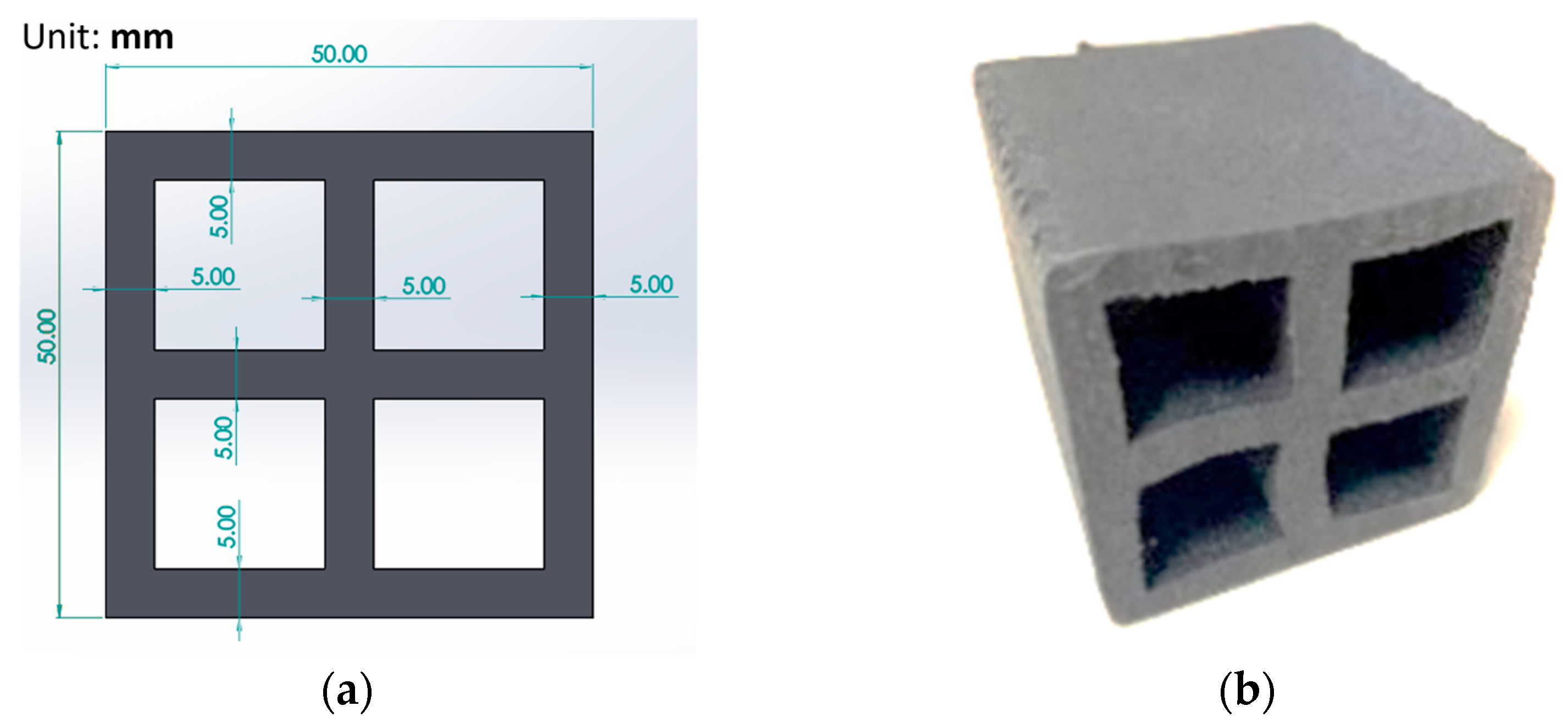
Figure 1. Rod design: (a) cross dimensions, (b) photograph of fabricated rod.
Machines 10 01207 g001
Figure 2. Three-dimensional designs of all fasteners.
Machines 10 01207 g002
Figure 3. Position and identification number of all fastener types. The symbols, i.e., (AH), denote the corresponding fasteners shown in Figure 2.
Machines 10 01207 g003
Figure 4. (a) Setup for static stress analysis of the simple greenhouse. (b) Locations where the maximum deflections along the x-axis, y-axis, and z-axis occur under the force 11 wind load.
Machines 10 01207 g004
Figure 5. (a) von Mises stress, (b) safety factor of fastener B under x-axis bending moment.
Machines 10 01207 g005
Figure 6. (a) von Mises stress and (b) safety factor of fastener E under x-axis bending moment.
Machines 10 01207 g006
Figure 7. (a) Von Mises stress, (b) safety factor of fastener D under y-axis bending moment.
Machines 10 01207 g007
Figure 8. (a) Von Mises stress and (b) safety factor of fastener E under y-axis bending moment.
Machines 10 01207 g008
Figure 9. (a) Von Mises stress and (b) safety factor of fastener F under y-axis bending moment.
Machines 10 01207 g009
Figure 10. Assembly of fasteners and rods: (a) fastener A, (b) fastener B, (c) fastener C, (d) fastener D, (e) fastener E, (f) fastener F, (g) fastener G1, (h) fastener G2, and (i) fastener H.
Machines 10 01207 g010aMachines 10 01207 g010b
Figure 11. Photograph showing completed greenhouse.
Machines 10 01207 g011
Table 1. Material properties of the rod.
CharacteristicValue
melting point (°C)230
glass transition temperature (°C)72
heat resistance temperature (°C)210
maximum tensile strength (MPa)71.7847
elongation (%)6.5
maximum bending strength (MPa)122.5831
flexural modulus of elasticity (GPa)4.4130
hardness (Shore D) ASTM D224080
density (g/cm3)1.43
Table 2. The axial tension and bending moment of all fasteners.
FastenerAxial Tension (N)X-Axis Bending Moment (N mm)Y-Axis Bending Moment (N mm)
A2169.23249,932.28208,126.53
B1737.10249,932.30208,126.50
C1941.7259,085.10226,268.80
D2004.48164,339.80649,484.60
E2144.71399,503.31646,375.91
F2004.48201,193.23190,347.08
G12156.48189,895.97189,895.97
G22156.48189,895.97189,895.97
H1796.58201,193.2391,417.59
Table 3. Von Mises stress and safety factor of all fasteners.
Axial Tension ForceX-Axis Bending ForceY-Axis Bending Force
Fastenervon Mises (MPa)Safety Factor (μL)von Mises (MPa)Safety Factor (μL)von Mises (MPa)Safety Factor (μL)
A16.338.15117.51.93139.61.37
B316.71.2526.30.71261.41.25
C56.233.6551.584.43198.51.84
D37.95.9999.931.91336.50.53
E139.32.06274.20.93540.30.47
F15.279.1698.821.57319.50.94
G114.5910.03158.41.8483.571.71
G223.476.79182.41.8278.891.86
H12.9211.6597.41.7468.354.14
Table 4. Axial tension and bending moment of all fasteners.
Fastener
Frequency (Hz)ABCDEFG1G2H
F1219.57187217.28179.9194.82215.73214.64194.92202.84
F2220.07199.01220.45181.1196.17264.2216.31209.31204.81
F3224.59224.76234.38212.19223.53264.52253.71222.44222.58
F4278.8586.76277.51220.23249.13683.12257.22257.38249.18
F5280.34598.12280.45236.46261.19686.03272.97267.17264.43
F61037.22638.96592.46606.93655.45689.34692.2604.44659.33
F71109.22942.11627.35649.66671.461072.69705.02627.11662.78
F81125.7970.63636.89678.37716.41243.86705.42699.79679.57
F91153.651076.54966.17839.54923.451274.131056.12993.81005.71
Publisher’s Note: MDPI stays neutral with regard to jurisdictional claims in published maps and institutional affiliations.