Article

Study on Dynamic Lubrication Characteristics of the External Return Spherical Bearing Pair under Full Working Conditions

School of Mechanical Engineering, Anhui University of Science and Technology, Huainan 232001, China
*
Author to whom correspondence should be addressed.
Machines 2022, 10(2), 107; https://doi.org/10.3390/machines10020107
Submission received: 29 December 2021 / Revised: 26 January 2022 / Accepted: 27 January 2022 / Published: 29 January 2022

Abstract

:
In order to study the frictional lubrication characteristics of a piston pump under varying loads and speeds in actual work, mathematical models, such as a cylinder dynamics model, cylinder micro-motion model, and external return spherical bearing pair lubrication model, were established under full working conditions. The influence of different parameters on the lubrication characteristics of the external return mechanism under full working conditions was analyzed. The results show that in a working cycle, when the pump was at low working pressure, the maximum value of the maximum oil film pressure increased with an increase in the cylinder block speed, which is basically consistent with the ideal conditions. With an increase in the working pressure, the maximum value first decreased and then increased with an increase in the cylinder block speed. When the cylinder block speed was constant, the total friction power increased with an increase in the working pressure and the internal as well as external swash plates’ inclination; considering the contact surface roughness of a friction pair under full working conditions, the total friction power increased by 46.8% compared with the ideal working conditions. The axial leakage flow increased with an increase in the external swash plate inclination and remained unchanged with an increase in the internal swash plate inclination. This research is beneficial for improving the lubrication theory of the external return mechanism and lays a foundation for improving its working performance.

1. Introduction

The return mechanism is an important part of a piston pump; it is the connection device of the three key friction pairs (i.e., slipper pair [1,2], plunger pair [3,4], and port pair [5,6]) of a piston pump. During the operation of a piston pump, on the one hand, the return mechanism provides the preload of the slipper pair and port pair to ensure that the cylinder block, port pair, and slipper pair are in a floating state, so that the slipper pair and port pair can achieve the best oil film thickness of the hydraulic static balance. On the other hand, it can provide the return force for the piston to ensure the volume change in the piston cavity and complete the purpose of the piston pump to transport oil. Therefore, the return mechanism has always been a topic focused on by experts, scholars, and research institutes at home and abroad. Noah D. Manring et al. [7] analyzed the track line and relative velocity of the contact points between a return plate and a ball hinge. Chen and Yang [8,9] conducted a collisional analysis of the return plate of a piston pump in addition to the optimization and improvement of relevant structures so as to achieve the purpose of the safe operation of the return plate without damage. Wang et al. [10] conducted finite element analysis on the return plate of a piston pump and discussed the stress distribution of the return plate. Ji et al. [11] analyzed the structure and force of the return mechanism of an inclined piston pump with a conical cylinder block. Zhang et al. [12] constructed a rigid–flexible coupling dynamics model of a piston pump based on ADAMS and ANSYS, and simulated and analyzed the force law of a return plate and the factors affecting the force state. Wang et al. [13] studied the oil film lubrication mechanism of a ball hinge pair of a return plate through a JFO cavitation algorithm according to the geometric characteristics and relative motion relationship of the return plate and ball hinge.
The external row compression return mechanism (external return mechanism) is a new type of compression structure designed to adapt to the special mechanism of a double-row/multi-row piston pump, which is one of the important parts of a balanced double-row axial piston pump. The pressing force of the external return mechanism originates from the external circle of a retainer plate, which has the advantages of a large pressing torque and good self-balancing. Its structural characteristics are similar to the spherical sliding friction pair with the joint bearing [14] as the application background. Fang et al. [15] proposed the theoretical calculation method of spherical static contact stress distribution. Kazama et al. [16] studied the fluid film lubrication characteristics of friction pair of the hydrostatic spherical bearing of a swash plate axial piston pump under unsteady conditions. Lin et al. [17] used the power-law fluid model to deduce the Reynolds equation suitable for slider bearings, obtained the pressure and bearing capacity of hydrodynamic lubrication film, and calculated the changes in lubrication film thickness, bearing capacity, and the extrusion speed of lubricants with different power law indexes with time. Lin et al. [18] proposed a model that can accurately predict the transient lubrication process of bearings. Mukras et al. [19] proposed a numerical integration scheme and parallel calculation method based on the ANSYS software to solve the wear between two objects in swing contact. Yacout et al. [20] studied the Reynolds equation of centripetal inertia and surface roughness on hydrostatic inference spherical plain bearings. Xie et al. [21,22] studied the influence of the microroughness load ratio and asymmetric groove on the lubrication state and lubrication characteristics of a lubricated bearing interface. Tang et al. [23] deduced the Reynolds equation suitable for joint bearing and studied the influence of swing angular velocity and other parameters on the performance of the joint bearing. Goenka et al. [24] carried out static and dynamic analyses of the joint bearing by the finite element method. The above studies mainly focus on the axial piston pump return mechanism and spherical friction pair, and research on the external return mechanism is relatively sparse. Furthermore, current analyses of the dynamic characteristics [25], tribological characteristics [26], and frictional lubrication characteristics [27,28] of the external return pair have been carried out under ideal working conditions without considering the influence of the motion state of the cylinder block on the lubrication characteristics of the spherical bearing pair under actual working conditions.
This research focused on the external return mechanism of a double-row piston pump under full working conditions. A kinematic model of a double-row axial piston, an oil pressure model of the internal and external row piston cavity, a cylinder block dynamics model, a micro-motion dynamics model of a double-row cylinder block, and a bidirectional coupling model of the flow field of the external return spherical bearing pair and the cylinder block micro-deformation field were established. The lubrication characteristics of the external return spherical bearing pair of a piston pump under full working conditions were studied to further improve the kinematic characteristics of the external return mechanism as well as the lubrication theory of the external return disk–external spherical bearing friction pair to lay a foundation for improving its service life and working performance.

2. Mathematical Model of the External Return Spherical Bearing Pair under Full Working Conditions

According to the working principle of the external return spherical bearing pair of a balanced double-row axial piston pump, the external return spherical bearing pair is related to the movement of the cylinder block, the pressure fluctuation in the plunger cavity, and its dynamic characteristics. Therefore, a mathematical model of the external return spherical bearing pair under full working conditions should include a pump motion model, cylinder block dynamics model, external return spherical bearing pair lubrication model, plunger chamber oil pressure model, and oil film thickness equation.

2.1. Kinematic Model of a Balanced Double-Row Axial Piston Pump

Figure 1 is a kinematic model of a balanced double-row axial piston pump, where the intersection point of the principal axis and the central plane of the piston spherical hinge is coordinate origin O, the x-axis coincides with the principal axis and points to the swash plate, and the z-axis is parallel to the swash plate plane and points to the cross-section of the cylinder block.
The internal and external swash plates are kept fixed, and the spherical hinge center of the plunger–slipper assembly was used to characterize the movement behavior of the plunger. The coordinates of the external and internal plungers are described as follows:
{ x A i = R cos φ i tan β x 2 A i = R 1 cos φ 2 i tan β 2 y A i = R cos φ i y 2 A i = R 1 cos φ 2 i z A i = R sin φ i z 2 A i = R 1 sin φ 2 i
where φi is the rotation angle of the external plunger relative to the y-axis, and φ2i is the rotation angle of the internal plunger relative to the y-axis.
Taking the coordinate origin O as a reference, the displacement of the external plunger relative to the plunger cavity is SKi, and the displacement of the internal plunger relative to the plunger cavity is S2Ki:
{ S K i = x A i = R cos φ i tan β S 2 K i = x 2 A i = R 1 cos φ 2 i tan β 2
The maximum movement distance, HK, of the external row plunger and the maximum movement distance, H2K, of the internal row plunger can be described as:
{ H K = 2 R tan β H 2 K = 2 R 1 tan β 2
The linear motion linear velocity, vKi, and acceleration, aKi, of the external row plunger relative to the cylinder block in addition to the linear motion linear velocity, v2Ki, and acceleration, a2Ki, of the internal row plunger relative to the cylinder block can be described as:
{ v K i = ω R tan β sin φ i v 2 K i = ω R 1 tan β 2 sin φ 2 i a K i = ω 2 R tan β cos φ i a 2 K i = ω 2 R 1 tan β 2 cos φ 2 i

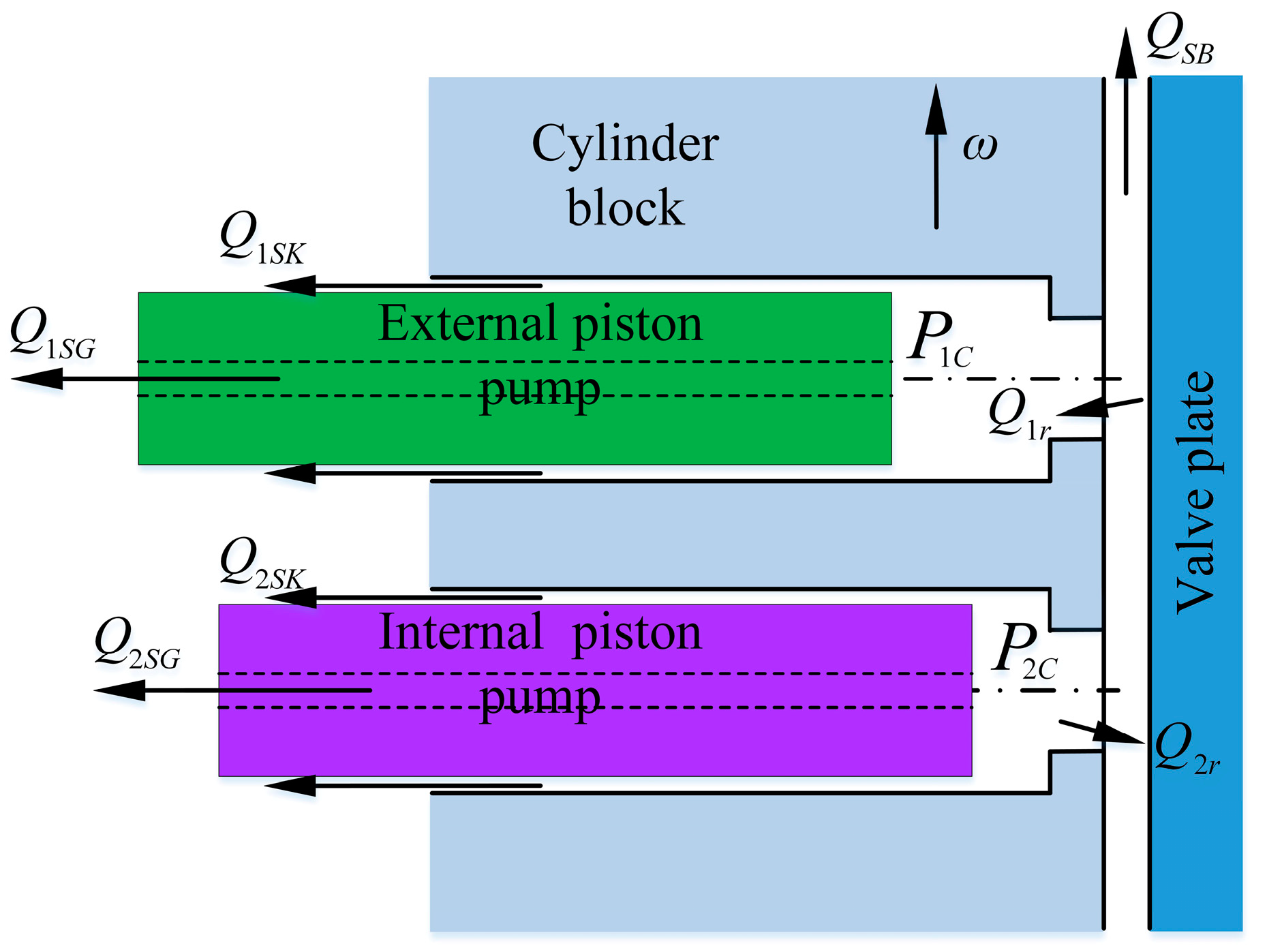
2.2. Oil Pressure Model of the Internal and External Plunger Cavity

The hydraulic oil in the plunger cavity is in direct contact with the plunger and the cylinder block, which is the main cause of the change in the movement posture of the cylinder block. As shown in Figure 2. The pressure characteristics of the internal and external rows of the plunger chamber of a balanced double-row axial piston pump are the same, and the change in the oil hydraulic pressure in the plunger chamber is shown in Formula (5):
d p e c d t = K V e ( Q e r + Q e S K + Q S B + Q e S G d V e d t )
where e = 1,2, respectively, representing the external row and internal row; K is the oil volume modulus; Ve is the actual oil volume of the e row plunger chamber; dVe/dt is the change rate of the e row oil volume; QeSK is the leakage of the e row plunger pair; QSB is the leakage of the valve plate pair; QeSG is the leakage of the slipper pair of the e row plunger; Qer is the flow rate of the e row plunger suction/discharge oil; pec is the working pressure of the e row plunger chamber.

2.3. Dynamic Model of an Underconstrained Double-Row Cylinder Block/Juncture

The force of an underconstrained double-row cylinder block is shown in Figure 3, including direct force and indirect force.

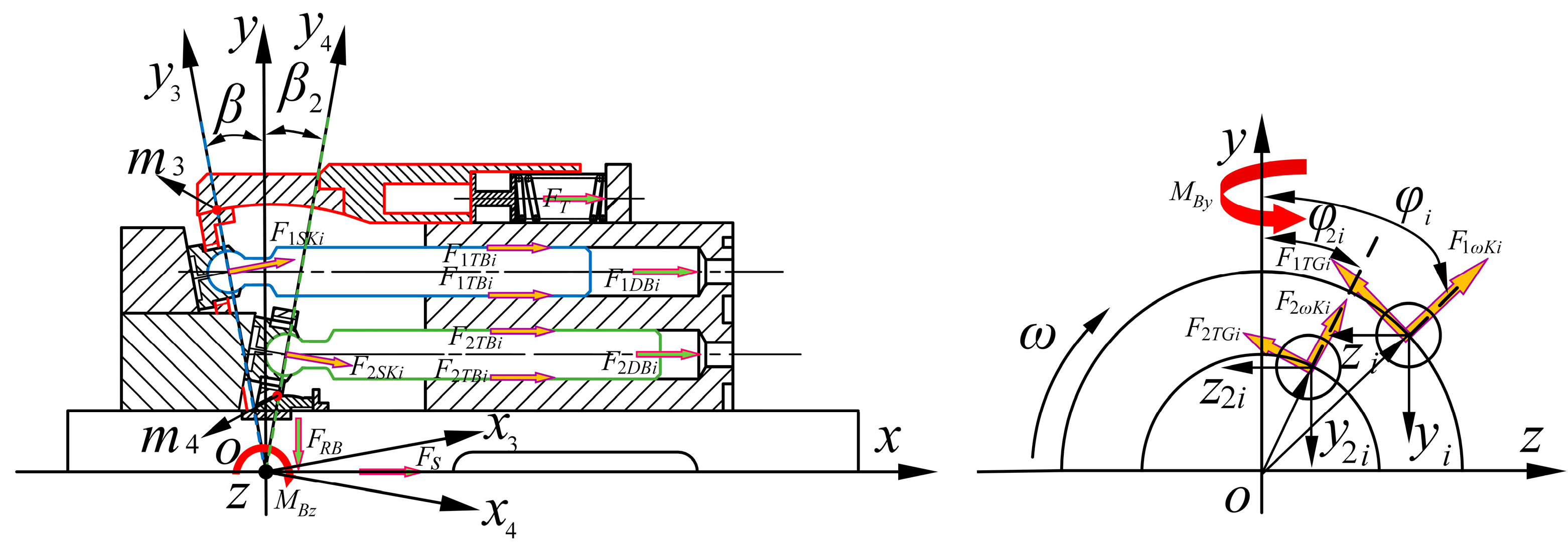
2.3.1. Direct Force Analysis of a Double-Row Cylinder Block

The direct force of a cylinder block includes the pressing force (FT) of the compression spring of the external return mechanism, the pressing force (FS) of the center spring of the internal return mechanism, the oil pressure of the external and internal plunger chambers (F1DBi and F2DBi), and the spindle spline force (FRB). Assuming that the pressing force of the compression spring and central spring does not change and that the midpoint of the spindle drive spline coincides with the origin (O), the pressing force (FBZx) in the x-axis direction, the torque (MBZz) around the z-axis, and the torque (MBZy) around the y-axis can be obtained as follows:
F B Z x = F s + i = 1 z F 1 D B i + 5 F T + i = 1 z F 2 D B i
M B Z z = i = 1 z F 1 D B i y i + i = 1 z F 2 D B i y 2 i
M B Z y = i = 1 z F 1 D B i z 1 i + i = 1 z F 2 D B i z 2 i
Oil hydraulic pressures F1DBi and F2DBi are:
F 1 D B i = p 1 c i A D
F 2 D B i = p 2 c i A D
where AD is the oil action area of the plunger cavity.

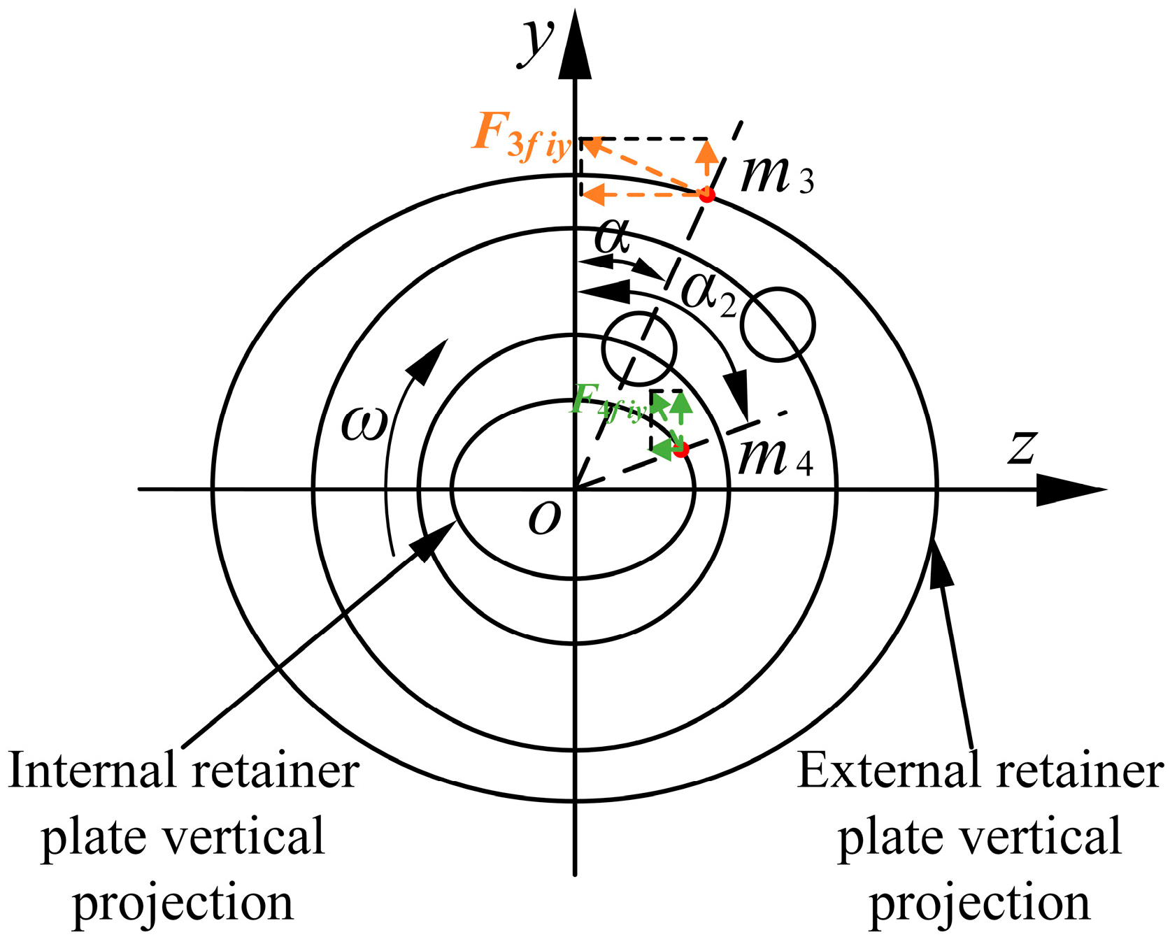
2.3.2. Indirect Force Analysis of a Double-Row Cylinder Block

The indirect force of a cylinder block is composed of the indirect force of the internal and external plunger–slipper pair in addition to the indirect force of the return retainer plate–spherical hinge pair. The indirect force of the plunger–slipper pair is transmitted to the cylinder block by the plunger pair including the swash plate to the plunger force, the inertia force of the plunger–slipper assembly, the friction force of the slipper pair, and the friction of the plunger pair. The indirect force of the external retainer plate–external spherical hinge pair is transmitted to the cylinder block by the external spherical hinge–external retainer plate assembly through the juncture and external retainer plate including the friction force of the external spherical hinge pair, the positive pressure between the spherical hinge pair, and the inertial force of the external retainer plate–external spherical hinge assembly. There is a direct force between the external retainer plate and slipper, the external spherical hinge, and the juncture stationary relative to the cylinder block; the inertia force is zero. The indirect force of the internal retainer plate–internal spherical hinge includes the friction force of the internal return spherical hinge pair and the inertial force of the internal retainer plate–internal spherical hinge assembly. The internal spherical hinge is stationary relative to the cylinder block, and the inertial force is zero; Reference [26] shows that it is difficult to form a complete oil film on the external return spherical hinge pair, and there is dry friction. Therefore, a tribological model of the spherical hinge pair includes a metal peak rough contact model and the oil film pressure equation.
To calculate the dry friction force of the external return spherical hinge pair, a concomitant coordinate system, O3-x3y3z3, was established, and a point, m3, was taken on the external retainer plate as shown in Figure 4a. The friction (F3fi) of m3 was divided into axial friction (F3fix) and tangential friction (F3fiy), where the axial friction (F3fix) and the axial partial force of the positive pressure of the spherical hinge pair act on the spherical hinge/juncture, which is balanced with the compression spring force; the tangential friction (F3fiy) acts on the external slipper. The concomitant coordinate system, O4-x4y4z4, was established and the point, m4, was taken on the internal retainer plate as shown in Figure 4b. Similarly, the dry friction force on the internal return spherical hinge pair could be analyzed. The tangential friction force of the internal and external spherical hinge pair is shown in Figure 5.
According to Reference [26], the force balance equation of the external retainer plate and external spherical hinge on the x-axis is:
F T Z = i = 1 m [ ( N 3 i ρ 5 i | ρ 5 i | ) i ( F 3 f i Δ V i | Δ V i | ) i ]
where FTZ is the total preload of the compression spring, and m is the number of evenly distributed contact points.
The vector equation, ρ5, and the relative motion velocity vector equation, ΔV, of the contact point in the external return spherical bearing pair are given in Reference [25]. According to Reference [26], the tangential friction of the contact point of the external return spherical hinge pair is:
F 3 f i y = ( f s N 3 i Δ V i | Δ V i | ) j
F 3 f i y = F 3 f i 2 F 3 f i x 2
From Reference [28], it can be known that the frictional force of the oil film of the external return spherical hinge pair is:
F φ = τ φ 1 R 2 sin θ d θ d φ
Similarly, the frictional forces, F4fiy and F4fix, at the contact point on the internal return spherical hinge pair and the oil film frictional force, Fφ2, can be obtained.
The x-axis pressing force (FBox), the torque (MBOz) around the z-axis, and the torque (MBoy) around the y-axis between the internal and external spherical hinge pair can be obtained:
F B O x = i = 1 m F 3 f i x + i = 1 m F 4 f i x + F φ sin γ 1 + F φ 2 sin γ 2
M B O z = i = 1 m ( F 3 f i x R M sin θ x cos α + F 4 f i x R 2 M sin θ 2 x cos α 2 ) + 0 φ ( F φ sin γ 1 R M sin θ x cos α + F φ 2 sin γ 2 R 2 M sin θ 2 x cos α 2 )
M B O y = i = 1 m ( F 3 f i y cos 2 α R M cos θ x sgn ( cos α ) + F 4 f i y cos 2 α 2 R 2 M cos θ 2 x sgn ( cos α 2 ) ) + 0 φ ( F φ cos γ 1 cos 2 α R M cos θ x sgn ( cos α ) + F φ 2 cos γ 2 cos 2 α 2 R 2 M cos θ 2 x sgn ( cos α 2 ) )
where tan α = R M sin χ R M cos β cos χ b f sin β [28], tan α 2 = R 2 M sin χ 2 R 2 M cos β 2 cos χ 2 b f 2 sin β 2 [29], θ x = π / 2 arctan ( b f R 2 ) β , θ 2 x = π arccos ( b f 2 R 3 ) β 2 , χ is the angle of the contact point m3 with the y3-axis in the O-x3y3z3 coordinate system, and χ2 is the angle of the contact point m4 with the y4-axis in the O-x4y4z4 coordinate system.
Considering the influence of the indirect force of the plunger–slipper assembly on a double-row cylinder block, the force on the plunger–slipper pair of the internal and external rows is shown in Figure 6.
Ignoring the rotation and fretting of the internal and external plungers, the force balance equations of the x-axis, y-axis, and z-axis directions of the internal and external plunger–slipper assembly are as follows:
{ F 1 s k i x + F 1 T k i F 1 D k i + F 1 A k i = 0 F 2 s k i x + F 2 T k i F 2 D k i + F 2 A k i = 0
{ F 1 s k i y + F 1 ω k i y + F 1 B k i y + F 1 T G i y + F 1 B L i sin φ i = 0 F 2 ω k i y F 2 s k i y + F 2 B k i y + F 2 T G i y + F 2 B L i sin φ 2 i = 0
{ F 1 ω k i z + F 1 B k i z F 1 T G i z F 1 B L i cos φ i = 0 F 2 ω k i z + F 2 B k i z F 2 T G i z F 2 B L i cos φ 2 i = 0
where F1ki and F2ki are the inertial force of the external and internal plunger–slipper assembly and act on the mass center of the plunger:
{ F 1 A k i = m k a K i = m k ω 2 R tan β cos φ i F 2 A k i = m k a 2 K i = m k ω 2 R 1 tan β 2 cos φ 2 i
F1ωki and F2ωki are the centrifugal force of the external and internal plunger–slipper assembly:
F 1 ω k i = m k ω 2 R           F 2 ω k i = m k ω 2 R 1
F1BLi and F2BLi are the forces acting on the external and internal rows’ slipper via the external and internal retainer plates, and the forces acting on the side of the slipper are equivalent to the center of the spherical hinge; F1Bki and F2Bki are the forces between the external and internal plunger.
The friction of the plunger cavity to the plunger:
{ F 1 T k i = f k F 1 B k i sgn ( v K i ) F 2 T k i = f k F 2 B k i sgn ( v 2 K i )
where fk is the friction coefficient of the plunger pair.
F 1 s k i x = F 1 s k i cos β           F 1 s k i y = F 1 s k i sin β
F 2 s k i x = F 2 s k i cos β 2           F 2 s k i y = F 2 s k i sin β 2
F1TGi and F1TGi are the sliding friction force between the external and internal slipper on the swash plate; acting on the side surface of the slipper is equivalent to the spherical hinge center. Under normal operation, the internal and external slipper in addition to the swash plate are always in the state of hydrodynamic lubrication; thus, the friction force of the swash plate on the internal and external rows’ slipper is:
{ F 1 T G i = η ω π ( R G 2 r G 2 ) R h G i F 2 T G i = η ω π ( R G 2 r G 2 ) R 1 h G 2 i
where RG is the external diameter of the slipper’s sealing belt, rG is the internal diameter of the slipper’s sealing belt, and hG and hG2 are the characteristic thickness of the sliding shoe pair oil film, which was taken as 10 μm.
F2Dki and F1Dki are the force acting on the plunger by the oil in the external and internal plunger chamber:
{ F 1 D k i = A K ( p 1 c i p e ) F 2 D k i = A K ( p 2 c i p e )
where AK is the cross-sectional area of the plunger, and pe is the oil leakage pressure of the slipper pair.
According to the balance equation of internal and external plunger–slipper assembly, the unique values of F1Bkiy, F1Bkiz, F1ski, F1Tki, F2Bkiy, F2Bkiz, F2ski, and F2Tki can be obtained by combining the above equations.
The x-axis pressing force (FBSx), the y-axis torque (MBSy), and the z-axis torque (MBSz) between the internal and external plunger–slipper components are obtained as follows:
F B S x = i = 1 z F 1 T B i + i = 1 z F 2 T B i
M B S y = i = 1 z ( F 1 T B i z 1 S i + F 1 ω k i z x 1 S i ( F 1 T G i z + F 1 B L i cos φ i ) x 1 A i F 2 T B i z 2 S i + F 2 ω k i z x 2 S i ( F 2 T G i z + F 2 B L i cos φ 2 i ) x 2 A i )
M B S z = i = 1 z ( F 1 T B i y 1 S i F 1 s k i y x 1 A i F 1 ω k i y x 1 S i F 1 T G i y x 1 A i F 1 B L i sin φ i x 1 A i + F 2 T B i y 2 S i F 2 s k i y x 2 A i F 2 ω k i y x 2 S i F 2 T G i y x 2 A i F 2 B L i sin φ i x 2 A i )
Combining the direct force of the cylinder block and the indirect force of the internal and external return spherical hinge pairs as well as the plunger pair, the underconstrained cylinder block pressure formula can be obtained:
{ F B x = F B Z x + F B O x + F B S x M B y = M B Z y + M B O y + M B S y M B z = M B Z z + M B O z + M B S z

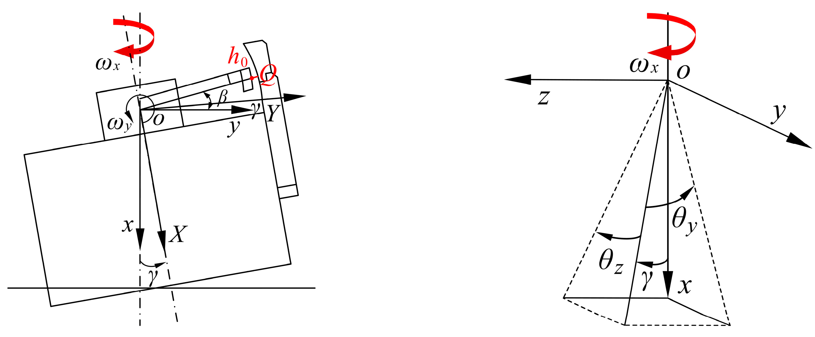
2.4. Tiny Movement Equation of a Double-Row Cylinder Block

From the underconstrained cylinder block pressure equation, it can be seen that the motion attitude of a cylinder block is affected by the external force and that a double-row cylinder block has subtle motion during the working process. Therefore, the concomitant coordinate system of a cylinder block is established to describe the spatial orientation of any point on the cylinder block, and the origin is determined according to the relative relationship between the principal and subordinate coordinates systems. The absolute coordinate system, O-xyz, and the inertial coordinate system, O-XYZ, are established as shown in Figure 7. The origin of the coordinate system coincides with the origin of Figure 3. When the pump is under normal working conditions, the tiny movement of the cylinder block is equally divided into two parts:

2.4.1. Tiny Linear Movement of a Cylinder Block along the x-Axis

The motion of the origin, O, of the absolute coordinate system along the x-axis is used to represent the tiny movement of the displacement of a double-row cylinder block along the x-axis; since the relative deflection of a cylinder block is small, the change in a double-row cylinder block on the x-axis can be used to represent the average oil film thickness, h, of the external return spherical hinge pair.
m G d 2 h sin ( β γ ) d t 2 = F b x
F b x = F B x + F f x
where Fbx is the sum of the forces on a double-row cylinder block in the x-axis direction, and Ffx is the oil supporting force of the valve pair.

2.4.2. Tiny Rotation of a Cylinder Block along with Origin O

Since a cylinder block is an axisymmetric rigid body, the tilted posture of a cylinder block is determined by the direction of the cylinder block axis relative to the inertial coordinate system, which can be represented by three mutually independent Euler angles. Therefore, the micro-rotation motion equation of the cylinder block is:
{ I t d 2 θ y d t 2 + ( I a I t ) d θ z d t ω = M b y I t d 2 θ z d t 2 + ( I t I a ) d θ y d t ω = M b z
M b y = M B y + M f y M b z = M B z + M f z
where Mby/Mbz is the sum of the acting moments acting on the y/z-axes, respectively, It/Ia is the moment of inertia of a cylinder block around the y/z-axes, respectively, and Mfy/Mfz is the oil supporting torque of the valve pair, respectively.

2.5. Mixed Fluid Lubrication Model of the External Return Spherical Hinge Pair

It can be seen from Reference [30] that the inertial coordinate system, O-XYZ, was consolidated on the external spherical hinge and that a double-row cylinder block deflects the γ angle to deflect O-XYZ together. From Figure 7:
sin 2 γ = sin 2 θ y + sin 2 θ z
According to the axial boundary conditions [18] of the external return spherical hinge pair and the deflection of the double-row cylinder block, the axial angle of point m3 is obtained:
θ = π / 2 + arctan ( b f R 2 ) + β γ
To consider the effect of dry friction on the performance of the external and internal return spherical hinge pair in practical work, pressure and shear flow factors are introduced into the Reynolds equation [28] of the external return spherical hinge pair under practical working conditions, and the average Reynolds equation representing the surface roughness peak of the external return ball hinge pair is obtained as follows:
φ ( ϕ φ h 3 p φ ) + θ ( ϕ θ h 3 p θ ) = 6 R 2 ω η [ ϕ c ( 0.5 R 2 ( sin θ + cos β ) sin 2 φ b f sin β sin φ ) h φ + 0.5 ϕ c R 2 ( 1 + sin ( θ + β ) ) sin 2 φ k 1 h φ + R 2 ϕ c sin φ ( cos θ h θ + cos ( θ + β ) k 1 h θ ) + R 2 ( sin θ + cos β ) cos 2 φ h b f sin β cos φ h + σ ϕ s θ + 2 ω ϕ c h t ]
where ϕθ is the axial pressure difference flow influence factor, ϕφ is the circumferential pressure difference flow influence factor, ϕs is the shear flow influence factor, ϕc is the contact factor, σ is the comprehensive surface roughness, σ = σ s 2 + σ c 2 , and σs and σc are the external spherical surfaces of the external retainer plate and the surface roughness of the internal spherical surface of the external spherical hinge, respectively.

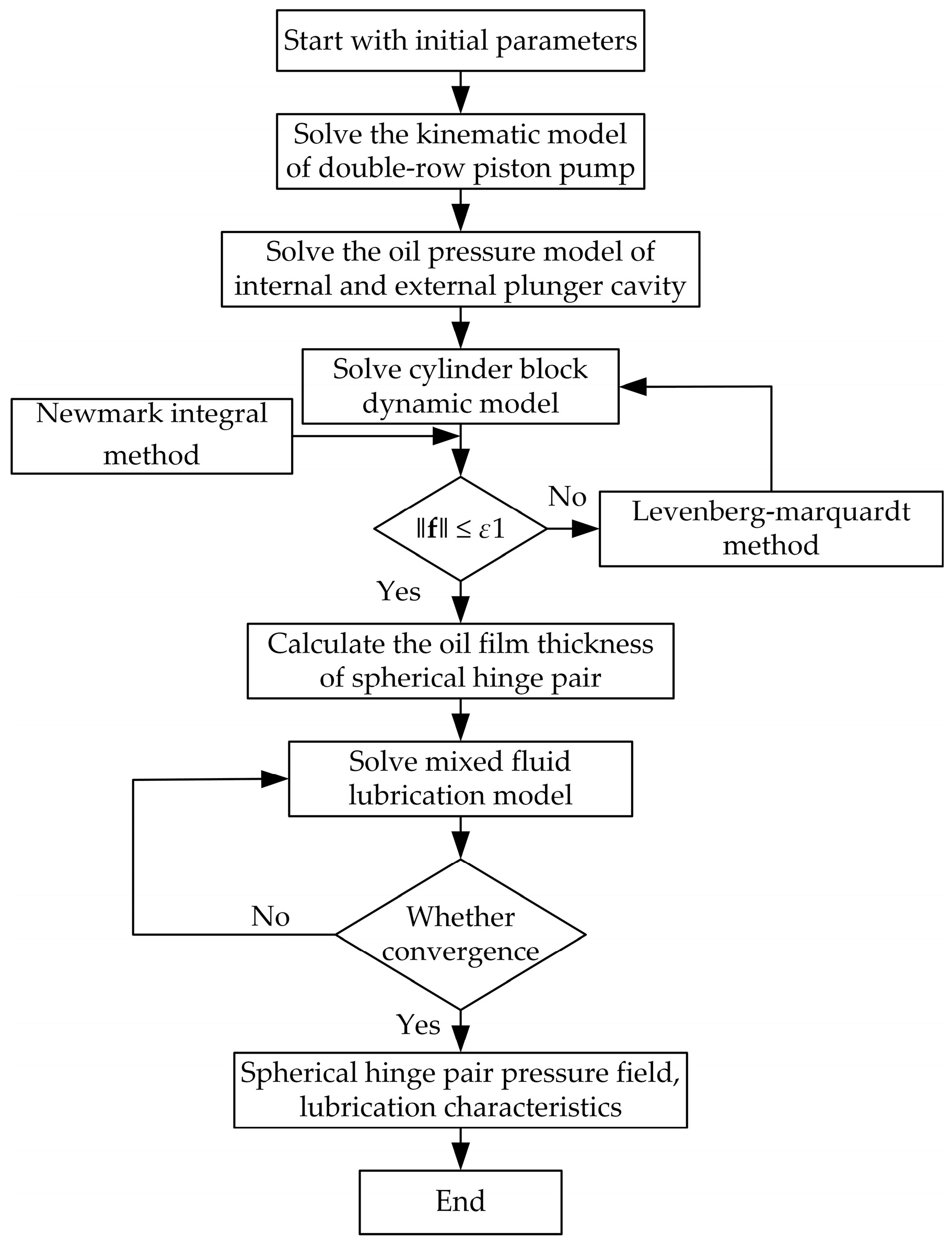
2.6. Mathematical Model Solving

In order to conveniently solve the dynamics model of a double-row cylinder block, Equations (32) and (33) are rewritten into Equation (39). Since the equation contains the oil film supporting force of the spherical hinge pair and port pair, the equations have nonlinear characteristics and are coupled together by oil film parameters.
{ d h ˙ 0 d t = F b x m G sin ( β γ ) d h 0 d t = h ˙ 0 d θ ˙ y d t = M b y ω ( I a I t ) θ ˙ z I t d θ y d t = θ ˙ y d θ ˙ z d t = M b z ω ( I t I a ) θ ˙ y I t d θ z d t = θ ˙ z
In terms of solving methods, the Newmark integral method with good convergence characteristics was adopted, and the dynamic parameters of the double-row cylinder block in the current time step are expressed as follows:
{ h ¨ 0 t = h 0 t h 0 t Δ t h ˙ 0 t Δ t Δ t a Δ t 2 ( 1 2 a 1 ) h ¨ 0 t Δ t   h ˙ 0 t = h ˙ 0 t Δ t + ( 1 b ) Δ t h ¨ 0 t Δ t + b Δ t h ¨ 0 t θ ¨ y t = θ y t θ y t Δ t θ ˙ y t Δ t Δ t a Δ t 2 ( 1 2 a 1 ) θ ¨ y t Δ t   θ ˙ y t = θ ˙ y t Δ t + ( 1 b ) Δ t θ ¨ y t Δ t + b Δ t θ ¨ y t θ ¨ z t = θ z t θ z t Δ t θ ˙ z t Δ t Δ t a Δ t 2 ( 1 2 a 1 ) θ ¨ z t Δ t   θ ˙ z t = θ ˙ z t Δ t + ( 1 b ) Δ t θ ¨ z t Δ t + b Δ t θ ¨ z t
where a and b are constants of the Newmark integral method: a = 0.25 and b = 0.5. The constant average acceleration method is used to calculate the initial oil film bearing capacity of the outer return ball hinged pair of a double-row cylinder block; the above equation is transformed into the least squares norm form as shown in Equation (41):
{ f 1 ( h 0 , θ y , θ z ) = F b x m G sin ( β γ ) h ˙ 0 f 2 ( h 0 , θ y , θ z ) = M b y ( I a I t ) θ ˙ z ω I t θ ¨ y f 3 ( h 0 , θ y , θ z ) = M b z ( I t I a ) θ ˙ y ω I t θ ¨ z
f = ( f 1 , f 2 , f 3 ) T
F = 1 2 f 2 = 1 2 ( ( F b x m G sin ( β γ ) h ¨ 0 ) 2 + ( M b y ( I a I t ) θ ˙ z ω I t θ ¨ y ) 2 + ( M b z ( I t I a ) θ ˙ y ω I t θ ¨ z ) 2 )
At the same time, the Newmark integral method can be used to obtain the velocity and acceleration values. The Levenberg–Marquardt method was used to solve it, and the iterative formula is as follows:
( J T J + μ d I ) h l m = J T f
where J is the Jacobian array of f about each variable, hlm is the change vector of each variable, and µd is the damping coefficient.
ε = 2 F n F n + 1 h l m T ( μ d h l m J T f )
Through the above iterative steps, the following convergence conditions are satisfied:
| F n F n + 1 | < ε 1
where ε1 = 10−3. The above steps were repeated in the next time step until the simulation model was solved. Then, the oil film parameters of the ball hinge pair were calculated according to Equations (36) and (37), and the mixed-fluid lubrication model of the outer return ball hinge pair was solved by combining the finite difference method and the overrelaxation iterative method [27]. The solution flow chart is shown in Figure 8.

3. Results and Analysis

The external return spherical hinge pair of a balanced high-flow double-row axial piston pump designed by the research group was taken as the calculation object (Table 1). According to the above calculation process and solved using MATLAB programming, the influence of different parameters on the lubrication characteristics of the external return ball hinge pair under all working conditions was analyzed.

3.1. Lubrication Characteristics of the External Return Spherical Hinge Pair

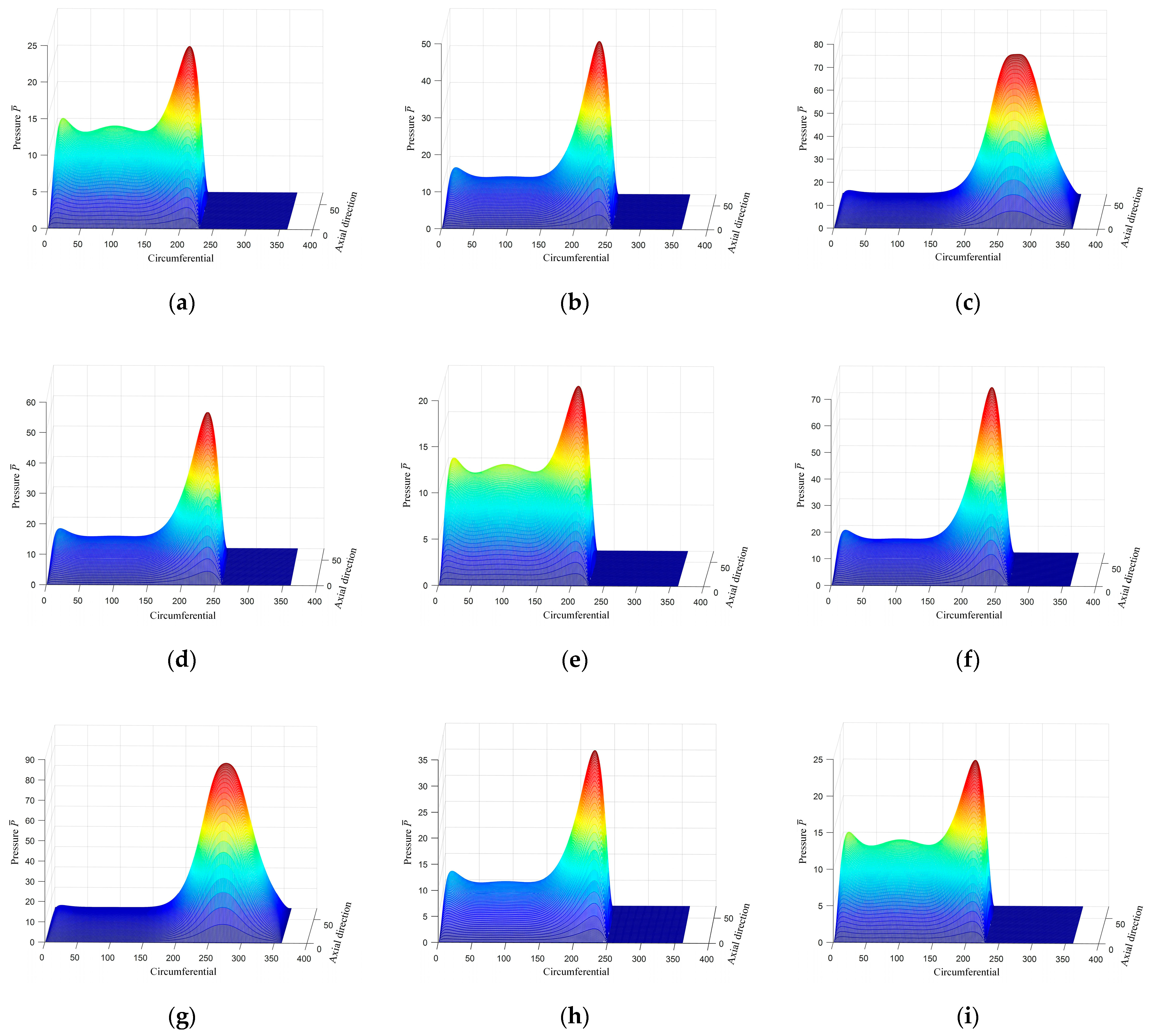
3.1.1. Analysis of Oil Film Pressure Characteristics

Figure 9 is the instantaneous oil film pressure distribution when the cylinder block speed was 1500 r/min, the working pressure was 20 MPa, the oil filling pressure was 1 MPa, and the inclination angles of the internal and external swash plates were 10°. The variation law of oil film distribution takes 40° as the cycle; thus, only the oil film pressure distribution regularity at 0–40° is shown in Figure 8. When the cylinder block angle was from 0° to 10°, the external return pair transient oil film pressure increased, accordingly; when a cylinder block turned from 10° to 20°, the transient oil film pressure decreased with an increase in the cylinder block angle. When the cylinder block angle increased from 20° to 30°, the transient oil film pressure reached the maximum value at 30°. When the cylinder block angle increased from 30° to 40°, the transient oil film pressure decreased.
Figure 10 shows the change in the maximum oil film pressure of the external return spherical hinge pair at a certain instant (cylinder block rotation 0°) under different working pressures (15.5, 25.5, 31.5, and 40 MPa) at n = 1500, 2500, and 3500 r/min. Figure 9 shows that when the cylinder block speed was 1500 r/min, the maximum value of the maximum oil film pressure increased with an increase in the working pressure, the maximum value gradually transited from the bottom dead point (cylinder block angle of 180°) to a cylinder block angle of 270°, and the maximum oil film pressure gradually changed from double peaks to a single peak. When the cylinder block speed was 2500 r/min, the maximum value will first decrease and then increases with an increase in working pressure, and when the speed was 3500 r/min, under different working pressures, the maximum value at this time decreased with an increase in working pressure.
When the pressure of a double-row axial piston pump was 15.5–25.5 MPa, the changing trend of the maximum oil film pressure was the same at different cylinder block speeds; that is, the oil film pressure increased with an increase in the cylinder block speed. When the pressure of a double-row axial piston pump was 31.5–40 MPa, the maximum oil film pressure changed significantly under different cylinder block speeds. When the rotational speed increased from 1500 to 2500 r/min, the maximum oil film pressure decreased and the maximum oil film pressure gradually transited from a cylinder block angle of 270° to the bottom dead point (cylinder block angle of 180°). When the rotational speed increased from 2500 to 3500 r/min, the maximum oil film pressure increased.

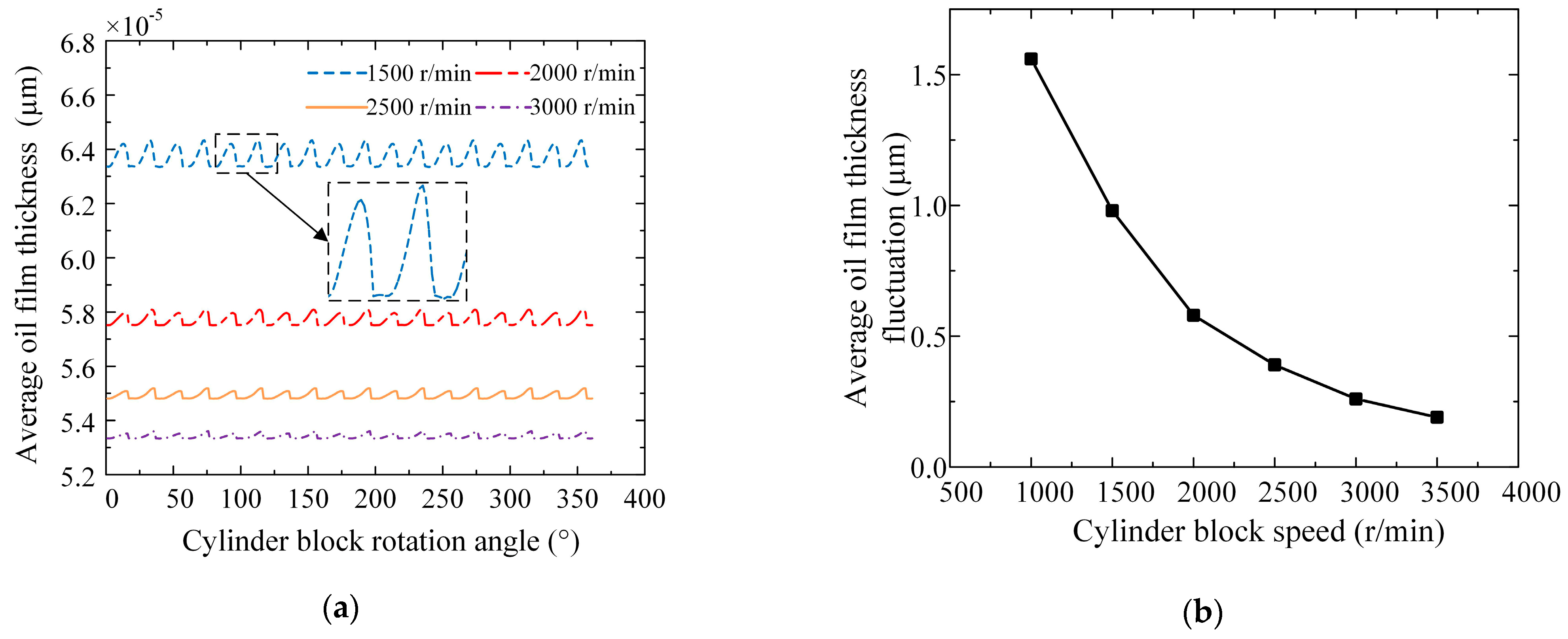
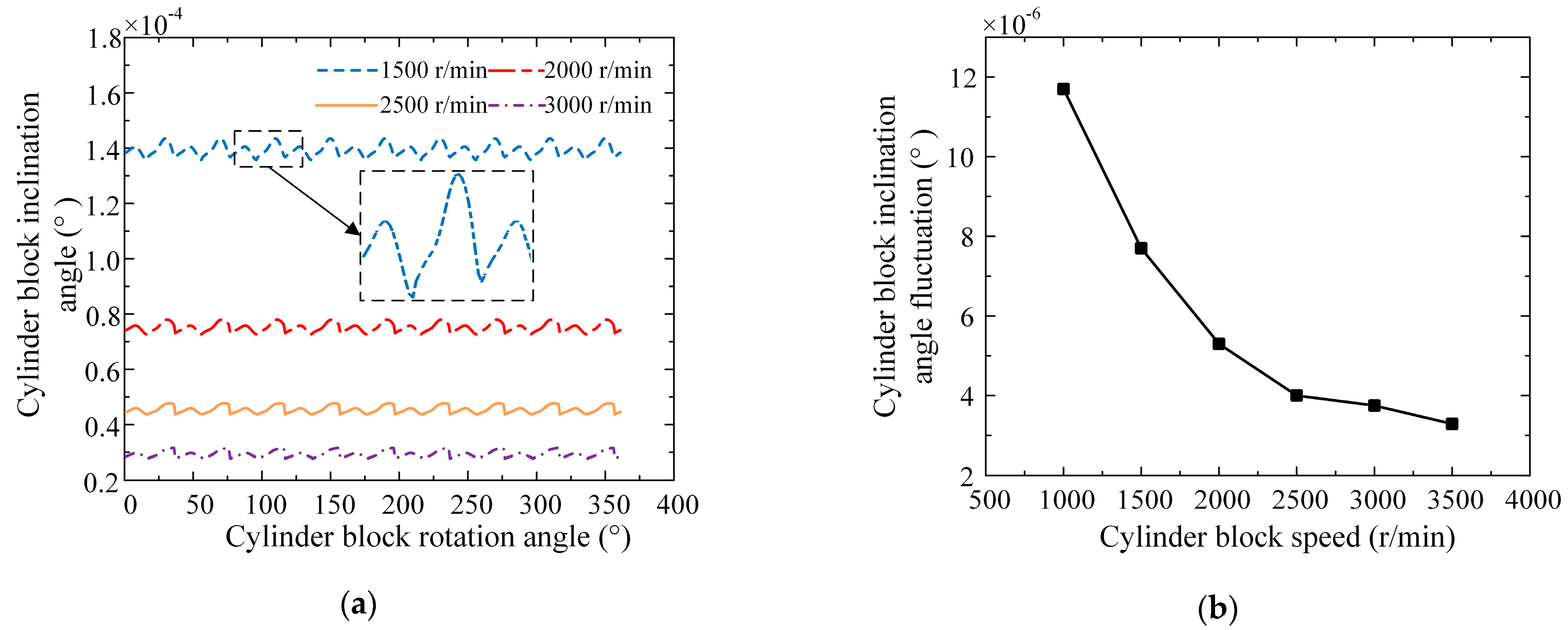
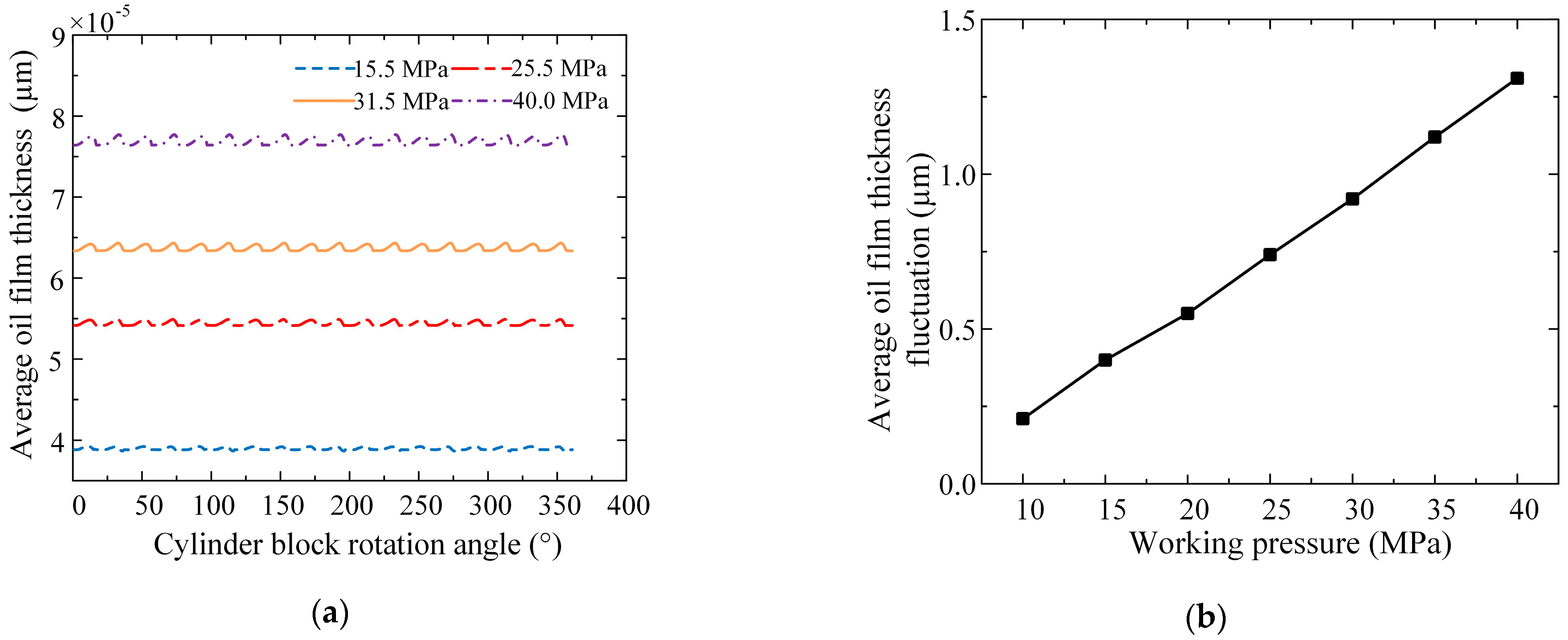
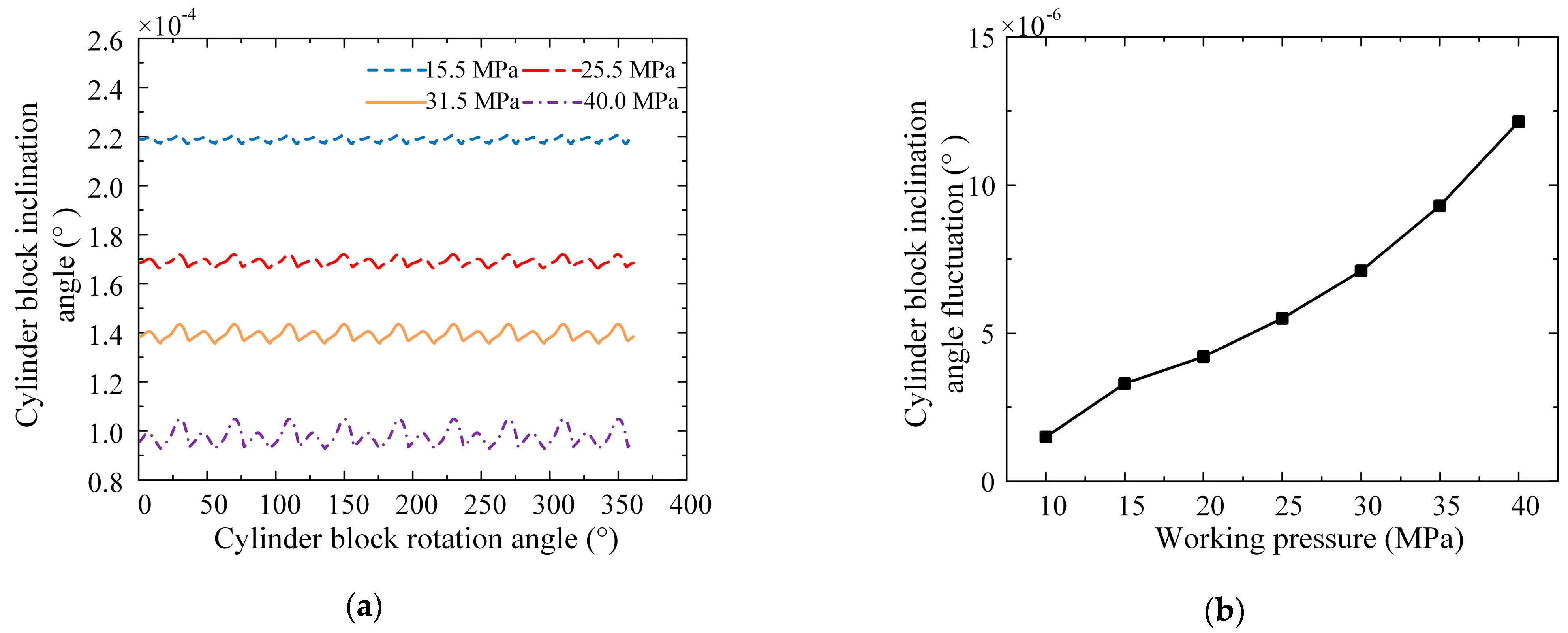
3.1.2. Influence of Operating Parameters on Oil Film Shape

Figure 11 and Figure 12 show the dynamic change characteristics of the oil film shape of the external return spherical hinge pair with the cylinder block rotation angle when the working pressure was 31.5 MPa, the oil filling pressure was 1 MPa, and the cylinder block speed was 1500, 2000, 2500, and 3000 r/min, respectively. It can be seen from Figure 10 and Figure 11 that the oil film thickness representing the oil film shape of the external return spherical hinge pair and the inclination angle of the movement posture of the cylinder block periodically changed with a cylinder block rotation angle of 40°; this is because the oil film shape of the external return spherical hinge pair was the result of the adaptive cylinder block load. The average oil film thickness at each cylinder block speed was 6.38, 5.70, 5.49, and 5.36 μm, and the fluctuation amplitude of the average oil film thickness was 0.987, 0.517, 0.465, and 0.271 μm. Under the same working pressure, the average oil film thickness decreased nonlinearly with an increase in cylinder block speed, and the average oil film thickness fluctuation decreased nonlinearly with an increase in cylinder block speed. The average of the cylinder block inclination angle at each cylinder block speed was 0.000142°, 0.0000759°, 0.0000462°, and 0.0000313°, and the fluctuation amplitude of the cylinder block inclination angle was 9.54 × 10⁻⁶, 7.62 × 10⁻⁶, 5.13 × 10⁻⁶, and 3.91 × 10⁻⁶°; under the same working pressure, the cylinder block inclination angle increased nonlinearly with an increase in rotational speed, but the fluctuation amplitude decreased.
Figure 13 and Figure 14 show the dynamic change characteristics of the oil film shape of the external return spherical hinge pair with the cylinder rotation angle when the cylinder speed was 1500 r/min, the oil filling pressure was 1 MPa, and the working pressure was 15.5, 25.5, 31.5, and 40 MPa, respectively. The average oil film thickness at each working pressure was 3.92, 5.48, 6.35, and 7.75 μm, and the fluctuation amplitude was 0.447, 0.787, 1.214, and 1.231 μm; under the same cylinder block speed, the average oil film thickness increased nonlinearly with an increase in working pressure, while the average oil film thickness fluctuation increased approximately linearly with an increase in working pressure. The average cylinder block inclination angle at each working pressure is 0.00022°, 0.000172°, 0.000142°, and 0.000101°, and the fluctuation amplitude was 3.34 × 10⁻⁶, 4.67 × 10⁻⁶, 7.72 × 10⁻⁶, and 16.21 × 10⁻⁶°; under the same cylinder block speed, the cylinder block inclination angle and fluctuation amplitude increased with an increase in working pressure.

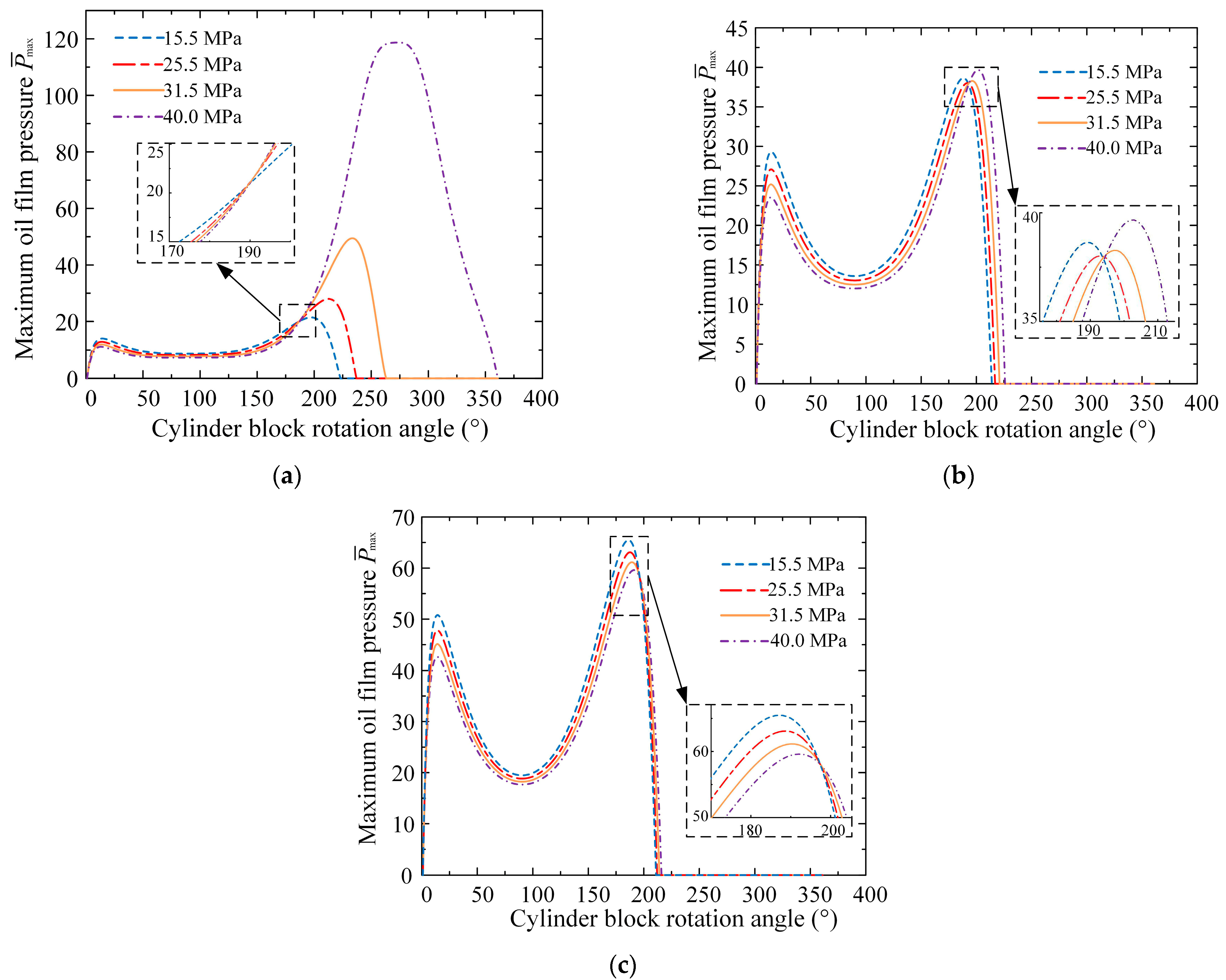
3.1.3. Influence of Operating Parameters on Lubrication Characteristics

Figure 15 shows the curves of the friction characteristics of the external return spherical hinge pair varying with the cylinder block speed under different working pressures. It can be seen from Figure 15a that the total friction power increased with an increase in cylinder block speed under the same working pressure and that the growth rate of the total friction power tended to be stable with an increase in cylinder block speed; the total friction power increased with an increase in the working pressure at the same cylinder block speed, but the increased rate of the total friction power decreased with an increase in pressure. It can be seen from Figure 15b that under different working pressures, the friction coefficient of the external return spherical hinge pair changed significantly with the cylinder block speed; when the working pressure was 15.5–25.5 MPa, the friction coefficient decreased first and then increased with an increase in the cylinder block speed; when the working pressure was at high pressure, the friction coefficient decreased with an increase in cylinder block speed.
Figure 16 shows the curves of the axial leakage flow of the external return spherical hinge pair varying with the cylinder block speed under different working pressures. It can be seen from Figure 16 that when the working pressure was 31.5 MPa, under different cylinder block speeds, the axial leakage flow was 11.66, 17.50, 23.32, 29.16, 34.99, and 40.83, indicating that the axial leakage flow increased approximately linearly with an increase in the cylinder block speed under the same working pressure. Compared with the four curves, it was found that the higher the pressure, the greater the growth rate of the leakage with the cylinder block speed. When the cylinder block speed was 1500 r/min, the axial leakage flow corresponding to each pressure was 16.36, 17.50, 18.22, and 18.98, respectively. The axial leakage flow increased approximately linearly with increasing pressure at the same cylinder block speed, and the growth rate of the axial leakage flow with pressure at the same cylinder block speed was unchanged. It can be seen that the cylinder block speed affects the leakage characteristics of the external return spherical hinge pair more than the working pressure.

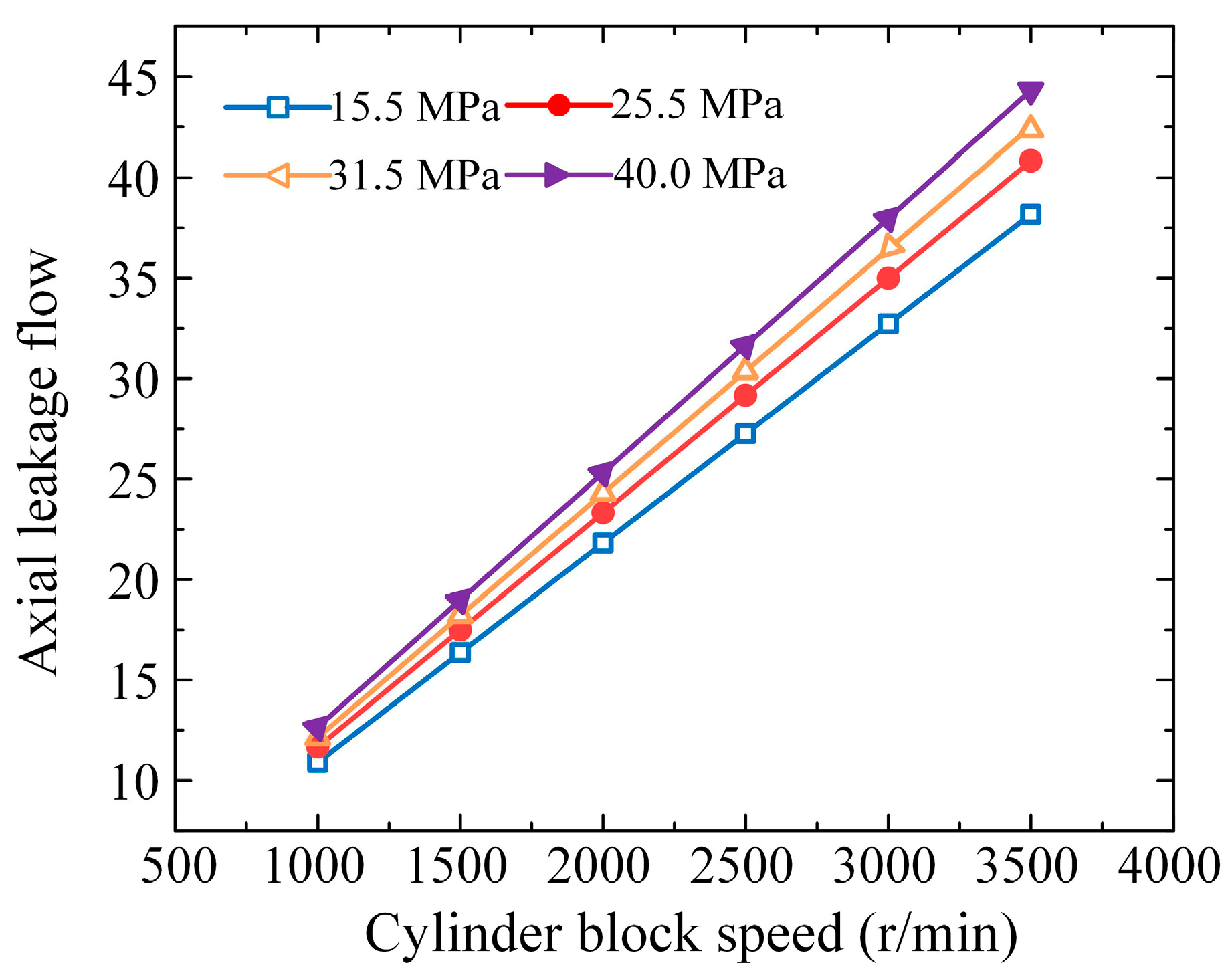
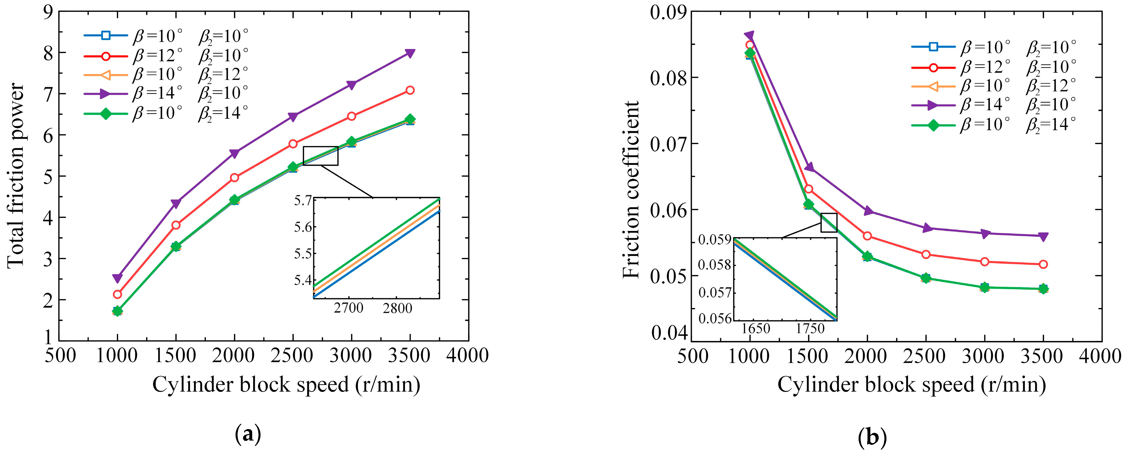
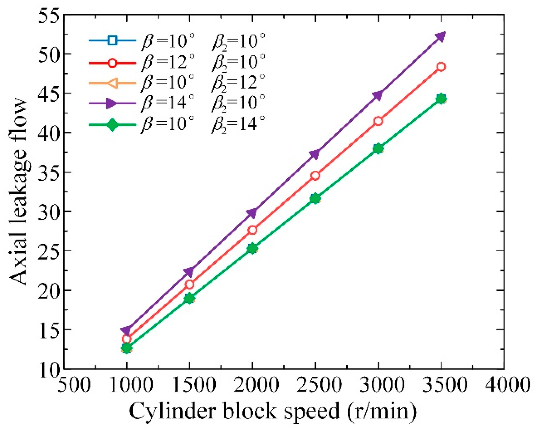
3.2. Friction and Leakage Characteristics of the External Return Spherical Hinge Pair

Figure 17 and Figure 18 show the effects of different inclination angles of the internal and external swash plates on the friction characteristics and leakage characteristics of the external return spherical hinge pair when the working pressure was 31.5 MPa. It can be seen from Figure 17a,b that under the condition of a constant cylinder block speed, with an increase in the internal and external swash plates’ inclination, both the friction power and friction coefficient increased. However, compared with the external swash plate inclination, the role of the internal swash plate inclination can be ignored. When n = 1500 r/min, the friction power under the external swash plate inclination β = 12° increased by 23.6% compared with β = 10°, and the friction coefficient increased by 0.72% compared with β = 10°. The friction power of an inclination β = 14° of the external swash plate increased by 25.6% compared with β = 12°, and the friction coefficient increased by 2.98% compared with β = 12°. When n = 3500 r/min, the friction power under the external swash plate inclination β = 12° increased by 11.9% compared with β = 10°, and the friction coefficient increased by 7.7% compared with β = 10°. Compared with β = 12°, the friction power under β = 14° increased by 12.9%, and the friction coefficient increased by 8.3%. Therefore, it can be seen that when the cylinder block speed was constant, the increasing degree of friction power and the friction coefficient increased with an increase in the external swash plate inclination. However, under the same external swash plate inclination, with an increase in the cylinder block speed, the increasing degree of the friction coefficient still increased, while the increasing degree of the friction power decreased.
It can be seen from Figure 18 that under the condition of a constant cylinder block speed, the axial leakage flow gradually increased with an increase in the external swash plate inclination. With an increase in the internal swash plate inclination, the axial leakage flow did not change. When n = 1500 r/min, the axial leakage flow under the external swash plate inclination β = 12° increased by 9.18% compared to β = 10°, while the axial leakage flow under the external swash plate inclination β = 14° increased by 8.0% compared to β = 12°. When n = 3500 r/min, the axial leakage flow under the external swash plate inclination β = 12° increased by 9.17% compared to β = 10°, while the axial leakage flow under the external swash plate inclination β = 14° increased by 7.99% compared to β = 12°.

4. Discussion

According to the analyses of Figure 9, Figure 11, Figure 12, Figure 13 and Figure 14, in a working cycle, the instantaneous oil film pressure field and oil film shape distribution rule of the external return spherical hinge pair under full working conditions changed adaptively with a change in the external load of a cylinder block, so that its change period and load fluctuation period were both 40°. The consideration of the tiny movement of the cylinder block under full working conditions increased the wedge angle of the oil film of the external return spherical hinge pair, which increased the dynamic pressure effect of the oil film compared to the ideal working conditions. The tiny movement of the cylinder block caused the shape of the oil film to continuously change, and it will inevitably produce a squeezing effect and improve the dynamic lubrication performance of the oil film.
According to the analyses of Figure 10a–c, it can be seen that the dynamic lubrication of the external return spherical hinge pair under different cylinder block speeds and working pressures was different from the ideal working conditions. When the pump was at a low working pressure, the oil film lubrication zone of the external return spherical hinge pair was in the range of 0–220° in circumference, and the maximum value was located near the bottom dead point, which is the same as the ideal working conditions. When the pump was at a high working pressure, the oil film lubrication regions increased gradually with a change in cylinder block speed in the circumferential direction. With the circumferential expansion of the oil film lubrication regions, the maximum value of the instantaneous oil film pressure gradually approached 270° from the bottom dead point, forming a larger dynamic pressure effect range and making the instantaneous oil film pressure in the whole working conditions increase by 27.6% compared with the ideal working conditions; the increasing degree increased gradually with a change in the cylinder block speed.
According to the analyses of Figure 15 and Figure 17, the cylinder block speed, working pressure, and swash plate inclination all led to an increase in the total friction power, resulting in greater heat generated between friction pairs, which results in lower oil viscosity, lower bearing capacity of spherical hinge pairs, and aggravating friction and wear between friction pairs. The consideration of the contact surface roughness under the full working conditions caused the total friction power to increase by 46.8% compared with the ideal working conditions, and the increasing degree increased with increasing working pressure. Compared with the ideal working conditions, the friction and wear between the friction pairs were more likely to be aggravated.
From the analysis of Figure 16 and Figure 18, it can be seen that the cylinder block speed, working pressure, and swash plate inclination can increase the axial leakage flow of the external return mechanism, which is conducive to the exchange of lubricating oil between the external return mechanism and the release of heat between the friction pairs of the external return mechanism.

5. Conclusions

In this paper, a mathematical model of the external return spherical hinge pair under full working conditions was established through a two-way coupling model of a flow field and an oil film micro-deformation field of the external return spherical hinge pair. The influence of different parameters on the lubrication characteristics of the external return mechanism under full working conditions was solved, and the following conclusions were drawn:
(1) The instantaneous oil film pressure field of the external return spherical hinge pair changes with a change in the external load of the cylinder block. In a working cycle, it changed periodically with the period of 40°. Under low working pressure, the oil film pressure of the spherical hinge pair was similar to that under ideal working conditions. The maximum oil film pressure increased with an increase in the cylinder speed and was located near the bottom dead point. Under high working pressure, the maximum oil film pressure of the external return mechanism decreased first and then increased with an increase in the cylinder block speed and gradually transitioned from a cylinder block angle of 270° to the bottom dead point;
(2) In a working cycle, the oil film shape of the external return spherical hinge pair changed periodically. The oil film thickness of the spherical hinge pair, the inclination angle of the cylinder block, and their fluctuation amplitude all decreased with an increase in the cylinder speed. The oil film thickness increased with an increase in the working pressure, and the fluctuation amplitude of the oil film thickness increased linearly with an increase in the working pressure. The cylinder block inclination decreased with an increase in the working pressure, while its fluctuation amplitude increased with an increase in working pressure;
(3) An increase in the working pressure, cylinder block speed, and internal as well as external swash plate inclination will increase the friction power. The friction coefficient of the external return mechanism decreased first and then increased with an increase in the cylinder block speed under low working pressure. At high working pressure, the friction coefficient decreased with an increase in the cylinder block speed. When the cylinder block speed was constant, an increase in the inclination angle of the internal and external swash plate increased the friction coefficient;
(4) An increase in the working pressure and cylinder block speed will increase the axial leakage. At the same cylinder block speed, the axial leakage increased with an increase in the external swash plate inclination, while the internal swash plate inclination had little effect on the axial leakage.

Author Contributions

Conceptualization, H.D.; methodology, H.D.; software, P.Z.; validation, C.H.; formal analysis, T.H.; investigation, H.D.; resources, H.D.; data curation, H.D.; writing—original draft preparation, P.Z.; writing—review and editing, H.D. and P.Z.; project administration, H.D.; visualization, C.H.; supervision, T.H. All authors have read and agreed to the published version of the manuscript.

Funding

This research was funded by the University Synergy Innovation Program of Anhui Province (grant number: GXXT-2020-061); the National Natural Science Foundation of China (grant number: 51575002); the University Synergy Innovation Program of Anhui Province (grant number: GXXT-2019-048).

Institutional Review Board Statement

Not applicable.

Informed Consent Statement

Not applicable.

Data Availability Statement

Not applicable.

Conflicts of Interest

The authors declare no conflict of interest.

Nomenclature

xAi, yAi, zAi The coordinates of the external row plunger
x2Ai, y2Ai, z2AiThe coordinates of theinternalrow plunger
R, R1The distribution circle radius of external plunger and the distribution circle radius of internal plunger (m)
β, β1The inclination of the external swash plate and the inclination of the internal swash plate (°)
φi, φ2iThe rotation angle of the external plunger relative to the y-axis and the rotation angle of the internal plunger relative to the y-axis (°)
KThe oil volume modulus (Pa)
ADThe oil action area of the plunger cavity (m2)
N3iThe positive pressure at point m3 (N)
N4iThe positive pressure at point m4 (N)
ρ5The vector equation of the contact point in the external return spherical bearing pair
ΔVThe relative motion velocity vector equation of the contact point in the external return spherical bearing pair
fsCoefficient of the sliding friction between the external retainer plate and the external spherical hinge
Fφ, Fφ2The oil film frictional force of the external return spherical bearing pair and the oil film frictional force of internal return spherical bearing pair (N)
τφ1Fluid shear stress component of the external return spherical bearing pair (MPa)
R2, R3The radius of the external retainer plate and the radius of the internal retainer plate (m)
bf, bf2Deviation distance of external retainer plate and the deviation distance of the internal retainer plate (m)
RMInternal surface radius of the external spherical hinge (m)
R2MExternal surface radius of the internal spherical hinge (m)
xSi, ySi, zSiThe coordinates of the centroid of the external plunger–slipper assembly
x2Si, y2Si, z2SiThe coordinates of the centroid of the internal plunger–slipper assembly
lDistance between the center of spherical hinge and the centroid of plunger–slipper assembly (m)
ωAngular velocity of the cylinder block (rad/s)
fkThe friction coefficient of the plunger pair
RG, rGThe external diameter of the slipper’s sealing belt and the internal diameter of the slipper’s sealing belt (m)
It, IaThe rotational inertia of the cylinder block around the y-axis was 0.191 kg·m2, and the rotational inertia of the cylinder block around the z-axis was 0.0889 kg·m2
AKThe cross-sectional area of the plunger (m2)
peThe drainage pressure of the slipper pair (MPa)
pPressure of oil film of external spherical hinge pair (MPa)
mkThe weight of plunger (kg)
mGThe weight of cylinder block (kg)
hThe average oil film thickness (m)
γThe tilt angle of cylinder block (°)

References

  1. Zhang, J.H.; Chao, Q.; Xu, B.; Pan, M.; Wang, Q.N.; Chen, Y. Novel three-piston pump design for a slipper test rig. Appl. Math. Model. 2017, 52, 65–81. [Google Scholar] [CrossRef] [Green Version]
  2. Xu, B.; Li, Y.B.; Zhang, B.; Zhang, J.H. Numerical simulation of overturning phenomenon of axial piston pump slipper pair. J. Mech. Eng. 2010, 46, 161–168. [Google Scholar] [CrossRef]
  3. Li, D.L.; Fang, M.S.; Deng, Y.P.; Liu, Y.S.; Wu, D.F. Study of materials for piston pairs of water hydraulic piston pump. Chin. Hydraul. Pneum. 2017, 11, 12–16. [Google Scholar]
  4. Wang, D.; Li, Z.Y.; Zhu, Y.Q. Study of the key problems in a water hydraulic piston pump and its applications. Ind. Lubr. Tribol. 2013, 53, 211–216. [Google Scholar]
  5. Wang, Z.Q.; Xu, Y.F.; Hu, S.; Ji, H.; Yang, J. Research on lubrication mechanism with fluid-solid coupling of port plate pair in swash plate axial piston pump. Proc. Inst. Mech. Eng. Part J J. Eng. Tribol. 2019, 234, 515–529. [Google Scholar] [CrossRef]
  6. Ji, Z.L. Research on thermal-fluid-structure coupling of valve plate pair in an axial piston pump with high pressure and high speed. Ind. Lubr. Tribol. 2018, 6, 1137–1144. [Google Scholar] [CrossRef] [Green Version]
  7. Manring, N.D. The relative motion between the ball guide and slipper retainer within an axial-piston swash-plate type hydrostatic pump. J. Dyn. SYST-T ASME 1999, 121, 518–523. [Google Scholar] [CrossRef]
  8. Chen, C. The Simulation Analysis of Collision Interference on Retainer Plate of Axial Piston Pump and Its Structure Optimizing Design. Master’s Thesis, Lanzhou University of Technology, Lanzhou, China, 2018. [Google Scholar]
  9. Yang, F.L. The Simulation and Optimum Design on Retainer Plate of Axial Piston Pump Based on Multi-Body Dynamics. Master’s Thesis, Lanzhou University of Technology, Lanzhou, China, 2019. [Google Scholar]
  10. Wang, G.Z.; Zhang, Z.P.; Liu, H.L.; Ke, J.; Zhang, R. Optimization design of swivel plate for piston pump based on ANSYS Workbench. Mach. Des. Res. 2012, 28, 62–65. [Google Scholar]
  11. Ji, P.; Yang, F.Y.; Hu, M. Analysis and design of return mechanism of inclined piston pump with conical cylinder block. Chin. Hydraul. Pneum. 2011, 12, 35–38. [Google Scholar]
  12. Zhang, J.; Hu, L.; Li, X.J.; Shi, W.D. The dynamic characteristic simulation of retainer plate in axial piston pump based on virtual prototype technology. Chin. Hydraul. Pneum. 2016, 3, 86–91. [Google Scholar]
  13. Wang, T.; Mao, M.; Tang, S.S.; Gai, J.T.; Ji, H. Research on lubrication mechanism of retaining spherical pair of variable displacement axial piston pump. Acta Armamentarii 2017, 38, 11–19. [Google Scholar]
  14. Wang, T.M.; Liang, B.; Zhao, W.H.; Tao, L.M.; Cui, W.Y. Study on the tribological properties of a self-lubricating spherical plain bearing at a cryogenic and wide temperature range. Sci. Sin. Technol. 2020, 50, 775–785. [Google Scholar] [CrossRef]
  15. Fang, Y.; Zhang, C.; Chen, X.; Wang, Y.; Tan, Y. A new universal approximate model for conformal contact and non-conformal contact of spherical surfaces. Acta Mech. 2015, 226, 1657–1672. [Google Scholar] [CrossRef]
  16. Kazama, T.; Tauruno, T.; Sasaki, H. Temperature measurement of tribological parts in swash-plate type axial piston pumps. In Proceedings of the JFPS International Symposium on Fluid Power, Toyama, Japan, 15–18 September 2008; Volume 2008, pp. 341–346. [Google Scholar]
  17. Lin, J.R.; Teng, M.Y.; Ho, M.H. Effects of non-Newtonian rheology on the film-height history between non-parallel sliding-squeezing surfaces. Proc. Inst. Mech. Eng. Part J-J. Eng. Tribol. 2007, 221, 155–159. [Google Scholar] [CrossRef]
  18. Lin, Q.Y.; Wei, Z.Y.; Wang, N.; Chen, W. Analysis on the lubrication performances of journal bearing system using computationalfluid dynamics andfluid–Structure interaction considering thermal influence and cavitation. Tribol. Int. 2013, 64, 8–15. [Google Scholar] [CrossRef]
  19. Mukras, S.; Kim, N.H.; Sawyer, W.G.; Jackson, D.B.; Bergquist, L.W. Numerical integration schemes and parallel computation for wear prediction using finite element method. Wear 2009, 266, 822–831. [Google Scholar] [CrossRef]
  20. Yacout, A.W.; Ismaeel, A.S.; Kassab, S.Z. The combined effects of the centripetal inertia and the surface roughness on the hydrostatic thrust spherical bearings performance. Tribol. Int. 2007, 40, 522–532. [Google Scholar] [CrossRef]
  21. Xie, Z.L.; Zhu, W.D. Theoretical and experimental exploration on the micro asperity contact load ratios and lubrication regimes transition for water-lubricated stern tube bearing. Tribol. Int. 2021, 164, 107105. [Google Scholar] [CrossRef]
  22. Xie, Z.L.; Wang, X.R.; Zhu, W.D. Theoretical and experimental exploration into the fluid structurecoupling dynamic behaviors towards water-lubricated bearingwith axial asymmetric grooves. Mech. Syst. Signal. Pr. 2020, 168, 108624. [Google Scholar] [CrossRef]
  23. Tang, Z.Q.; Liu, K.; Wang, W.; Liu, X.J. Numerical analysis of grease lubrication for radial spherical plain bearings in rotation and swing motion. Appl. Math. Mech. 2015, 36, 207–219. [Google Scholar]
  24. Goenka, P.K.; Booker, J.F. Spherical bearings: Static and dynamic analysis via the finite element method. J. Lubr. Technol. 1980, 102, 308–318. [Google Scholar] [CrossRef]
  25. Wang, Q.C. Kinematics and Friction Lubrication Analysis in the External Return Mechanism of Piston Pump/Motor. Master’s Thesis, Anhui University of Science and Technology, Huainan, China, 2019. [Google Scholar]
  26. Deng, H.S.; Hu, C.; Wang, Q.C.; Wang, L.; Wang, C.L. Friction and wear analysis of the external return spherical bearing pair of axial piston pump/motor. Mech. Ind. 2020, 21, 1–13. [Google Scholar] [CrossRef] [Green Version]
  27. Deng, H.S.; Wang, L.; Guo, Y.C.; Zhang, Y.; Wang, C.L. Analysis of the hydrodynamic lubrication characteristics of the external Return spherical bearing pair of an axial piston pump/motor. Math. Probl. Eng. 2020, 2020, 1–14. [Google Scholar] [CrossRef]
  28. Wang, L.; Deng, H.S.; Gou, Y.C.; Wang, C.L.; Hu, C. Lubrication characteristics of external return spherical hinge pair of axial piston pump or motor under combined action of inclination and offset distance. J. Cent. South. Univ. 2021, 28, 2375–2393. [Google Scholar] [CrossRef]
  29. Sun, Y.; Jiang, J.H.; Liu, J.L. Piston pump slipper chuck and ball head relative position and friction power consumption. J. South China Univ. Technol. 2011, 39, 82–87. [Google Scholar]
  30. Xu, L. Study on the Lubrication Characteristics of the Valve Plate Bearing in Hydraulic Axial Piston Pump. Ph.D. Thesis, Beijing Institute of Technology, Beijing, China, 2016. [Google Scholar]
Figure 1. Kinematic analysis of a balanced double-row axial piston pump.
Machines 10 00107 g001
Figure 2. Schematic diagram of the flow change in the internal and external row single-plunger cavities.
Machines 10 00107 g002
Figure 3. Schematic diagram of the pressing force of a double-row cylinder block.
Machines 10 00107 g003
Figure 4. Force analysis of the internal and external return mechanism: (a) force analysis of the external return mechanism; (b) force analysis of the internal return mechanism.
Machines 10 00107 g004
Figure 5. Schematic diagram of the tangential friction of the internal and external spherical hinge pair.
Machines 10 00107 g005
Figure 6. Force analysis of internal and external plunger–slipper pair: (a) x-o-y plane; (b) x-o-z plane; (c) y-o-z plane.
Machines 10 00107 g006
Figure 7. Schematic diagram of the cylinder block attitude.
Machines 10 00107 g007
Figure 8. The flow chart of the solution process.
Machines 10 00107 g008
Figure 9. Oil film pressure distribution of the external return spherical hinge pair under different cylinder block rotation angles: (a) 0°; (b) 5°; (c) 10°; (d) 15°; (e) 20°; (f) 25°; (g) 30°; (h) 35°; (i) 40°.
Machines 10 00107 g009
Figure 10. Maximum oil film pressure under different working pressures: (a) 1500; (b) 2500; (c) 3500 r/min.
Machines 10 00107 g010
Figure 11. Average oil film thickness and its fluctuation characteristics under different cylinder block speeds: (a) average oil film thickness; (b) average oil film thickness fluctuation.
Machines 10 00107 g011
Figure 12. Cylinder block inclination angle and its fluctuation characteristics under different cylinder block speeds: (a) cylinder block inclination angle; (b) cylinder block inclination angle fluctuation.
Machines 10 00107 g012
Figure 13. Average oil film thickness and its fluctuation characteristics under different working pressures: (a) average oil film thickness; (b) average oil film thickness fluctuation.
Machines 10 00107 g013
Figure 14. Cylinder block inclination angle and its fluctuation characteristics under different working pressures: (a) cylinder block inclination angle; (b) cylinder block inclination angle fluctuation.
Machines 10 00107 g014
Figure 15. Friction characteristics under different working pressures: (a) total friction power; (b) friction coefficient.
Machines 10 00107 g015
Figure 16. Axial leakage flow under different working pressures.
Machines 10 00107 g016
Figure 17. Friction characteristics under different internal and external swash plate inclinations: (a) total friction power; (b) friction coefficient.
Machines 10 00107 g017
Figure 18. Leakage characteristics under different internal and external swash plate inclinations.
Machines 10 00107 g018
Table 1. Main parameters.
ParametersValues
Distribution circle radius of external plunger, R (m)0.041
Distribution circle radius of internal plunger, R1 (m)0.024
Radius of external retainer plate, R2 (m)0.0725
Internal surface radius of external spherical hinge, RM (m)0.07255
External swash plate inclination, β (°)10
Internal swash plate inclination, β2 (°)10
Number of single row plungers, z9
Deviation distance of external retainer plate, bf (m)0.0031
Bulk modulus of oil, K (Pa)7 × 10⁸
Calibration spindle speed, n (r/min)1500
Weight of the plunger, mk (kg)0.15
External diameter of slipper sealing belt, RG (m)0.008
Internal diameter of slipper sealing belt, rG (m)0.005
Viscosity of lubricating oil, η (Pa·s)0.0129
Publisher’s Note: MDPI stays neutral with regard to jurisdictional claims in published maps and institutional affiliations.

