Article

Design, Development and Control of a Forming Robot for an Internally Fixed Titanium Alloy Strip

1
Cixi Institute of BioMedical Engineering, Ningbo Institute of Materials Technology & Engineering, Chinese Academy of Sciences, Cixi 315300, China
2
Ningbo Institute of Materials Technology and Engineering, Chinese Academy of Sciences, Ningbo 315201, China
3
Department of Oral and Maxillofacial Surgery, Center of Stomatology, Xiangya Hospital, Central South University, Changsha 410008, China
*
Author to whom correspondence should be addressed.
Machines 2022, 10(2), 68; https://doi.org/10.3390/machines10020068
Submission received: 5 December 2021 / Revised: 11 January 2022 / Accepted: 12 January 2022 / Published: 18 January 2022
(This article belongs to the Topic Robotics and Automation in Smart Manufacturing Systems)

Abstract

:
Medical titanium alloys are widely used in surgery, orthopedics, stomatology and other medical specialties because of their good biocompatibility. In traditional rigid internal fixation applications, titanium alloy strips or plates must be bent to fit the supported surface. Currently, the common practice is to bend titanium alloy bars in three degrees of freedom manually. However, it is difficult to ensure bending accuracy and achieve the best shape. In this study, we introduce a forming robot for internally fixed titanium alloy strips (FRIFTAS). The forming robot is a device that automatically reshapes the titanium strip with various specifications according to medical needs. Here, the design of mechanical and electrical systems and the development of the overall system are described to illustrate how a FRIFTAS is structured and designed. Three bending experimental tests are conducted. In the bending experiments, the robot bends an initial strip on the roll, pitch and yaw directions independently. The results show that the robot can bend a section of the alloy strip at the desired angle. Then, an overall reshaped titanium alloy strip experiment is discussed. The results show that the titanium-strip-forming robot is capable of automatically reshaping an internally fixed titanium strip. The proposed robot can perform the numerically controlled bending of the medical titanium strip according to physicians’ personalized requirements for surgery to improve the accuracy and efficiency of preoperative preparation and provide a better postoperative appearance and more effectively functioning treatment scheme for patients.

1. Introduction

The development of digital medicine has greatly improved the accuracy and speed of medical surgery. For example, in oral and maxillofacial surgery, widely used digital medical technology can design models and surgical tools according to individual bone shape. Therefore, the operation, which was completed in the surgical process, is advanced to the preoperative stage. Regarding the new technology’s application in digital medicine, titanium strip bending is the only existing process that has not been digitized and must still be operated manually. The operation of this process is cumbersome, inefficient, has poor precision and lacks repeatability.
Titanium strips are medical consumables with a special hole structure that must be bent according to the patient’s condition. The medical titanium strip was approved by Medical Device Approval III. Titanium strips are widely used in medicine. It must be used after trauma and tumor surgery, and there are many product specifications.
In rigid internal fixation technology, titanium strip repair can be applied to multiple site fractures with decent curative effects [1,2,3,4]. However, the bending of finished titanium strips is time-consuming, which leads to problems such as a decrease in physicians’ efficiency, a long duration of anesthesia and increases in drug use and cost.
In a routine operation, the titanium strip is bent by hand. However, it is difficult to ensure the bending accuracy and achieve the best shape. Repeated bending may also cause metal fatigue and reduce the mechanical properties of titanium strips. Several studies have indicated that the position of the titanium strip, whether it is repeatedly bent or the shape fits the bone surface will affect the postoperative healing of patients, and serious cases will lead to infection, titanium strip exposure, titanium strip fracture, bone necrosis and other problems.
The best way to improve manual bending is to process materials automatically by numerical control. Currently, the multipoint molding technology of titanium mesh and robot bending of medical Ni-Ti alloy wire have been developed, but the above methods cannot be used directly for titanium strip bending.
Clinically, with the development of robotics and control theory and the urgent need to release orthodontic physicians from heavy workloads, a new type of medical robot, such as robots that bend Ni-Ti alloy wire, has emerged [5].
Werner Butscher [6,7] proposed a robotic bending apparatus for automatically bending orthodontic archwires into a particular shape. The robot is known as the SureSmile archwire-bending robot. In addition to regular bending tools such as griping tools, the SureSmile robot incorporates force sensors that are used to determine the overbends needed to obtain the archwire’s desired final shape and may also include a resistive heating system in which the current flows through the wire while the wire is held in a bent position to heat it and thereby retain its bent shape.
Gilbert presented a LAMDA [8] system (Lingual Archwire Manufacturing and Design Aid) of lingual treatment that can be used in customized orthodontic archwire design [9]. This system can realize movement in the XY plane.
Y. Zhang proposed another archwire-bending robot based on MOTOMAN UP6. The archwire-bending robot is composed of PC, MOTOMAN UP6, and the archwire-bending actuator. The actuator matches the end of the MOTOMAN robot. The archwire-bending actuator, which connects with the MOTOMAN robot end, is used to clamp and bend the archwire [10,11].
J. G. Jiang recently developed a Cartesian-type archwire-bending robot [12,13,14,15]. The archwire-bending robot mechanism consists of the base, rotary, feed, supporting structure of the archwire, bending die and archwire-bending mechanism. Orthodontic archwire’s bending process is analyzed, and the structure of the orthodontic archwire-bending robot is designed using SolidWorks software. Precision control with a third-order pure S acc/dec profile of an archwire-bending robot is established [15]. Orthodontic archwire-bending experimentation is performed using a Cartesian-type archwire-bending robot. To compensate for the archwire’s springback phenomenon, the different types of archwires’ springback mechanical properties (including Ni-Ti alloy archwires) have been studied [16,17,18]. Moreover, to improve the Ni-Ti alloy wire-bending accuracy, a method for the digital expression and interactive adjustment of personalized orthodontic archwires is proposed [19]. The experimental results show that the position of each straight section can be adjusted using this method to change the arch shape of the orthodontic archwire. The error rate of the bent archwire ranged between 1.1% and 6.7%.
However, the current medical bending robot is used for oral titanium alloy archwires rather than titanium alloy strips. Compared with archwire bending, titanium alloy strip bending is different in that (1) compared with archwire bending, a titanium alloy strip needs to provide greater processing bending force to make it produce plastic deformation; (2) the archwire only needs to deform in 2 degrees of freedom (DOF) to fit the tooth shape, while the titanium alloy strip needs to deform in 3 degrees of freedom to fit the oral shape; (3) the structure of a titanium alloy strip and archwire is different, and its feeding mode will be greatly different in automatic machining.
To fix titanium strip bending in digital medical processes, a robot device is proposed in this study. The novel robot has the following characteristics: (1) by designing a new structure, the robot could bend a titanium alloy strip with 3DOF, so that the bent titanium alloy strip could fit the external shape of the specified mandible; (2) by selecting a compact high-power motor, the robot can produce large bending force and realize the bending of the titanium alloy strip; (3) by designing a new control program, the robot can realize automatic feeding for a specific titanium alloy strip.
According to medical needs, the proposed forming robot will reshape the titanium strip with various specifications. Forming is conducted automatically via digital measures. The system will refer to the manual bending medical specifications for force application to ensure that the formed materials meet the quality requirements of medical applications.
The robot can perform the numerically controlled bending of the finished medical titanium strip according to the physicians’ personalized requirements for surgery to improve the accuracy and efficiency of preoperative preparation and provide a better postoperative appearance and more efficiently functioning treatment scheme for patients.
In this study, the design of mechanical and electrical systems and the development of an overall system are described to illustrate how a FRIFTAS is structured and worked. We conducted experiments to show the bending performance of the robot in three bending directions. The preliminary results show that the titanium-strip-forming robot is capable of automatically reshaping an internally fixed titanium strip.

2. Materials and Methods

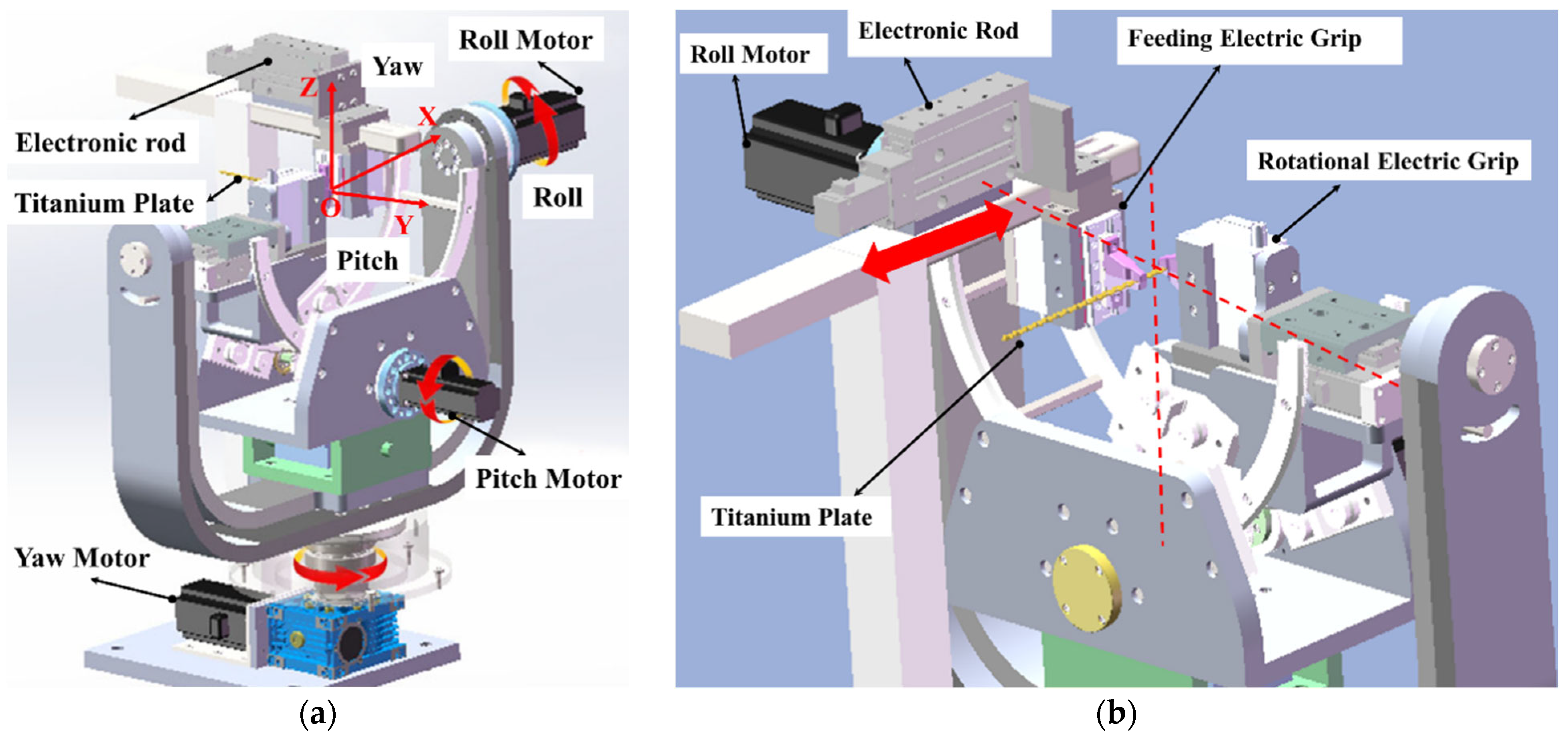
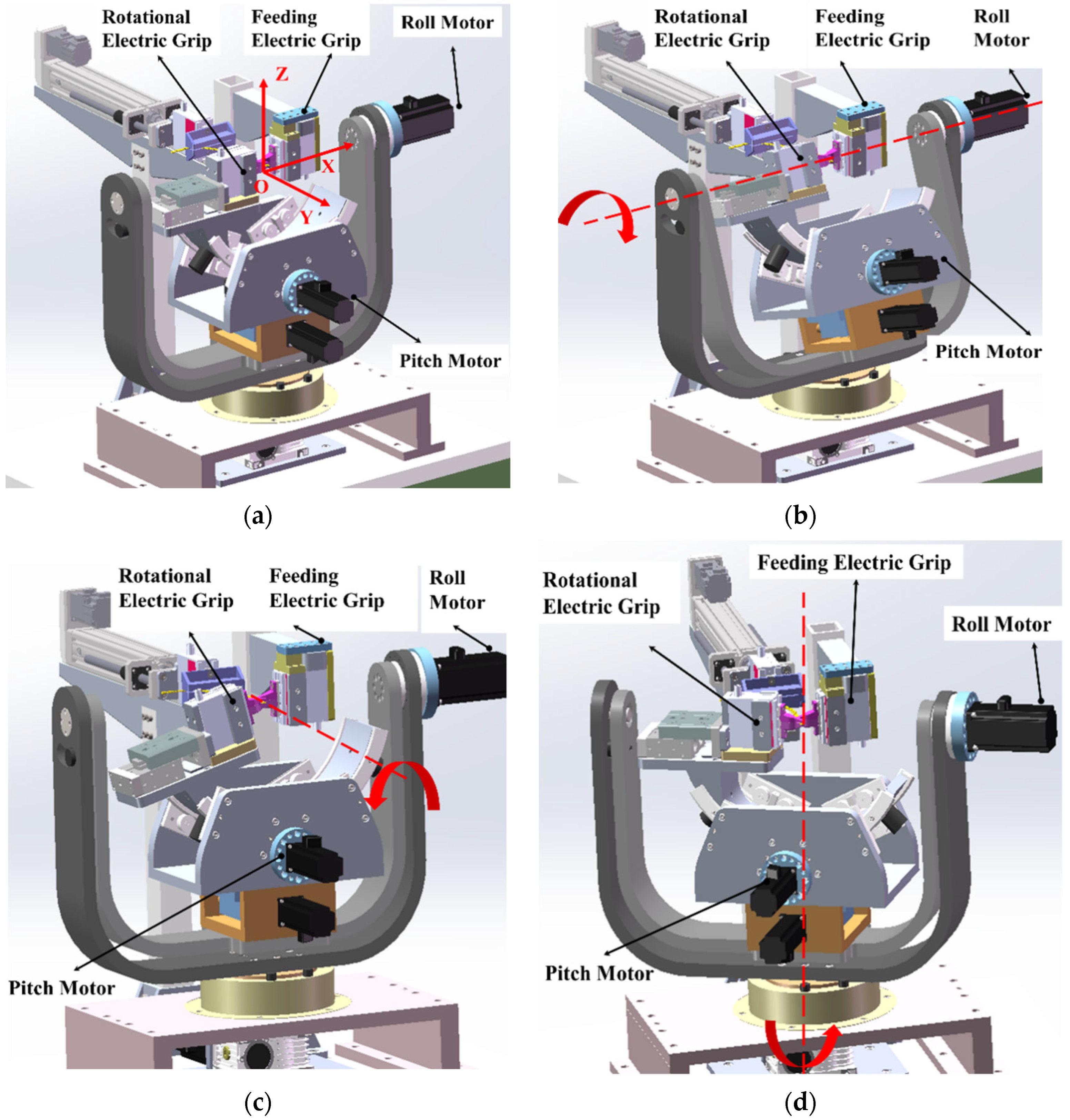
2.1. Mechanical System Design

The main structure of the forming robot consists of three motors, two electric grippers, one electronic rod and other supporting accessories, as shown in Figure 1.
The process of forming the titanium alloy strip is roughly illustrated as follows: (1) In the initial state, the two electric grippers grip two adjacent holes on the strip. (2) The motors independently drive the rotational electric gripper in three different directions as the controller commands. Titanium alloy strips are bent and formed by motors. The movements along each axis are shown in Figure 2. (3) The feeding electric gripper moves to the next titanium alloy strip hole and feeds the strip forward. (4) The rotational electronic gripper moves to the adjacent hole next to the feeding electric gripper.
The bending origin is designed as the mechanism by which three axes of roll, pitch, and yaw meet at one point to generate ball joint motion. The meeting point is in the middle of two holes in the titanium alloy strip. The position of the meeting point on the titanium alloy strip is shown in Figure 3.
According to the estimation of the conventional human jawbone 3D model, the maximum deformation angle of titanium alloy strips in each direction is ±18° in roll, ±12° in pitch and ±12° in yaw. Therefore, in this robot structure, the maximum machining angles designed in each direction are ±30° in roll, ±20° in pitch, and ±20° in yaw.
To determine the capacity of the actuator in the robot, static force analysis is performed. The material for the titanium alloy strip is TC4, and the composition is Ti6Al4V. By checking relevant parameters in the material handbook, the mechanical properties of titanium alloy strips at room temperature are shown in Table 1.
The titanium alloy strip is a rectangular porous strip. To simplify the calculation, the titanium alloy strip can be assumed to be a rectangular fastener. The geometric parameters of the titanium alloy strips are shown in Table 2. Since the yield strength and dimensional parameters of the titanium alloy strip are known, the minimum bending torque required for the titanium alloy strip to produce bending deformation can be obtained.
For the yaw direction, the bending section coefficient of the titanium alloy strip is expressed in Equation (1).
W Z = I z y max = b h 2 6 = 3 × 6 2 6 = 18   mm 3
In this way, the minimum bending force of the titanium alloy strip in the yaw direction is
M min [ δ ] × W z = 860   MPa × 18   mm 3 = 15.48   Nm
In the roll direction, the bending section coefficient of the titanium alloy strip is expressed in Equation (3), and the minimum bending force in roll is shown in Equation (4):
W Z = I z y max = b h 2 6 = 6 × 3 2 6 = 9   mm 3
M min [ δ ] × W z = 860   MPa × 9   mm 3 = 7.74   Nm
Similarly, the minimum bending force in the pitch direction can be estimated by Equations (5) and (6):
M min [ τ ] × α × W T = 0.577 × [ σ s ] × α × W T = 6.6   Nm
where
W T = b h 2 = 5.4 × 10 8   m 3
α = 0.246
Based on the maximum required torque estimation, an ST8N40P motor (100 W) with a nominal torque of 0.32 N·m and a nominal current of 4.7 A was selected for the driving roll and pitch direction, while an ST8N60P motor (200 W) with a nominal torque of 0.64 N·m and a nominal current of 12.5 A was selected for driving yaw direction.
To amplify motor torque, a 50:1 gear ratio is chosen. Thus, the roll and pitch output-driven torques at the nominal motor current will be 16 N·m, and the yaw output-driven torque at the nominal motor current will be 32 N·m. Since the maximum output torque is greater than the necessary torque at each axis, it is suitable to use ST8N40P and ST8N60P with a gear ratio of 50:1. A harmonic gear is chosen for the reduction gear since it has no backlash but has high torque transmission performance. Specifications of the motor and gear are summarized in Table 3.
A commercial steel frame, which has a high amount of strength, was used mainly for the main structure to provide sufficient strength to deform the titanium alloy strip. However, to reduce the robot’s weight, hollow aluminum is used as a U-shaped part. The whole platform size is approximately 540 mm × 520 mm × 450 mm.

2.2. Electronic System and Controller Design

2.2.1. Electronic Motors/Sensors

The forming robot uses two 320 W DC motors on roll and pitch and a 640 W DC motor on yaw. The motor controllers are ADM-15D80-EALT (Tech Servo Co.), which are able to control the positions of three motors based on position commands from the main controller. On each motor, an encoder detects the motor’s current position. The encoder signals of the forming robot are read by each motor controller and sent to the main controller using EtherCAT communication. All position data are sent to the main controller, which is used to process various control algorithms.
Two electrical grips are used to clutch the titanium alloy strip. The grip controllers are DL2-A28-20-AH5, which are able to control the distance of the grips by 0~20 mm. The communication interface of the grip is RS485.
An electronic rod is used to adjust the position of feeding grips. When the forming robot finishes bending, the electronic rod drives the feeding electric gripper to move to the next titanium alloy strip hole. The controller of the electronic rod is chosen to be a TC100-01-N1 server motor controller (TOYO CO.). The translational moving range is 0~100 mm, and the motor power is 40 W. RS485 is the communication protocol between the TC100 and main controller.
The sensors applied in the electrical grips and electronic rod are incremental encoders that provide the current position of the motors.

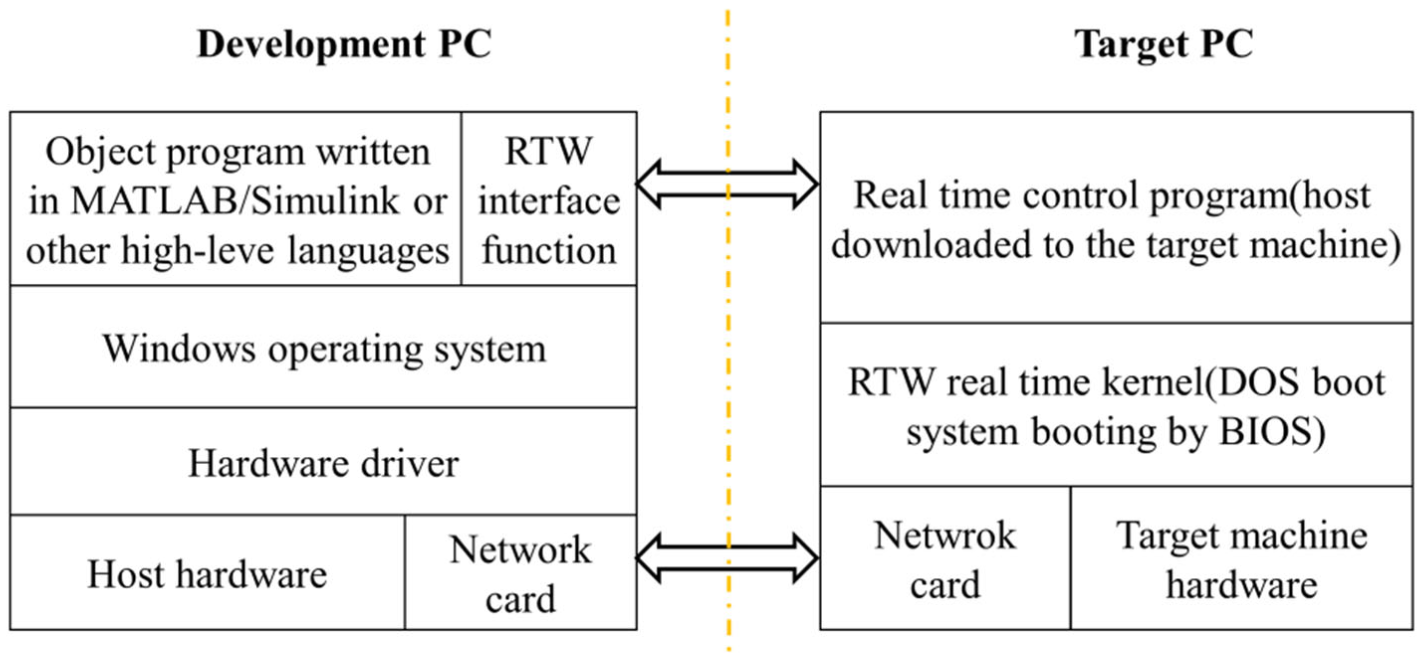
2.2.2. Real-Time System

A Simulink real-time system is chosen to be the forming robot’s main control system. A real-time integrated PC is essential for calculating the control algorithm of the entire system.
Simulink Real-time (RTW) combines the functions of the XPC Target and XPC Target Embedded Option, allowing one to create real-time applications from the Simulink model and run them on dedicated target computer hardware connected to the physical system. It supports real-time simulation and testing, including rapid control prototyping, DSP and visual system prototyping, and hardware in the loop-HIL simulation.
The control algorithm of the forming robot is conducted on the hardware in the loop platform. The hardware in the loop platform is built with the help of the rapid control prototype RCP (Rapid Control Prototype) technology, using MATLAB simulation tools, the real-time online simulation of the control system, the online modification of parameters, online recording data and other functions. The system framework is shown in Figure 4.
RTW can use the driver block to extend the Simulink model, automatically generate real-time applications and perform interactive data or automatic running programs on a dedicated target computer equipped with a real-time kernel, multicore CPU, universal I/O and protocol interfaces. Simulink and the hardware design of the target computer collaborate to create a real-time system for interactive interfaces and on-site environments. RTW can also be used with custom target computers and I/O hardware.
In the forming robot control system, BOX-6639 (AAEON CO.) is selected as the target PC. It is a compact fanless box PC incorporated with a variety of serial I/O connectors, including 6 COM ports, 4 USB 3.2 Gen 1 and 34 channel DIO which offer flexible configurations and expansion capabilities. An overall specification of the real-time target PC is described in Table 4.

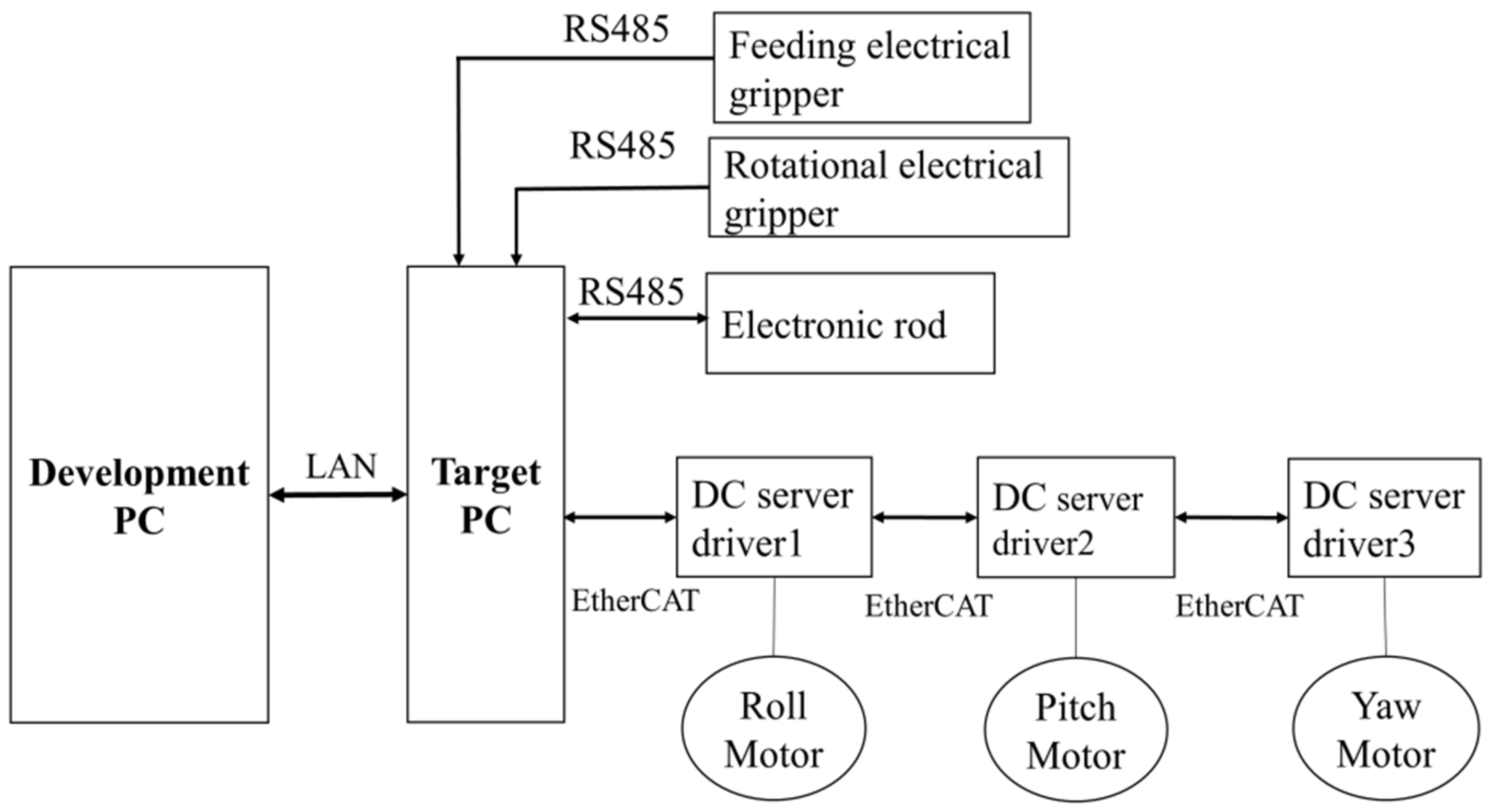
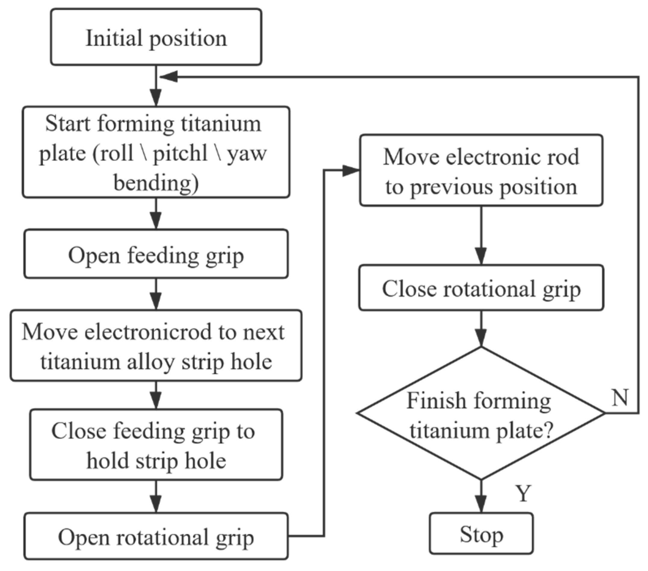
2.2.3. Overall Control System Architecture

An overall control system architecture integration is shown in Figure 5. We command the desired bending angle and combined movement using the development PC. The receiver is the target PC, which is connected via LAN communication. Three server motors are on the forming robot. The motors on roll and pitch of the forming robot are 320 W DC server motor for high acceleration performance. The motor on yaw direction is a 640 W DC server motor. The three DC motors are connected via a target PC using EtherCAT as their communication protocol. There is an encoder for position control of each motor. The encoder signals are read by the motor controller.
In total, 3 RS485 interfaces are used to control the feeding electrical gripper, rotational electrical gripper and electronic rod. The sensors applied in the electrical grips and electronic rod are incremental encoders that provide the motors’ current positions.
During the working process, the target PC runs a Simulink real-time kernel. In the control experiments, the sampling rate is 1 kHz. On the development PC, a Microsoft Windows operating system is chosen on which the host control software is developed.

3. Results

Figure 6a shows the overall experimental device of the forming robot for internally fixed titanium alloy strips. The main hardware includes two 320 W DC server motors for bending the roll and pitch, a 640 W DC server motor for forming the yaw direction, two electrical grips for feeding and rotating, and an electronic rod for feeding one grip to the next titanium strip hole. Figure 6b depicts the closer view of the top of the forming robot. When the robot is bending the titanium strip, the feeding grip and rotational grip hold the adjoining two holes to change the shape of the titanium strip.
The flowchart of the forming robot operation is shown in Figure 7. Once the robot starts to operate, all variables and settings are initiated, and the robot’s standard position is set using home detection. Once all settings are completed, the robot begins operation based on the inserted setting.

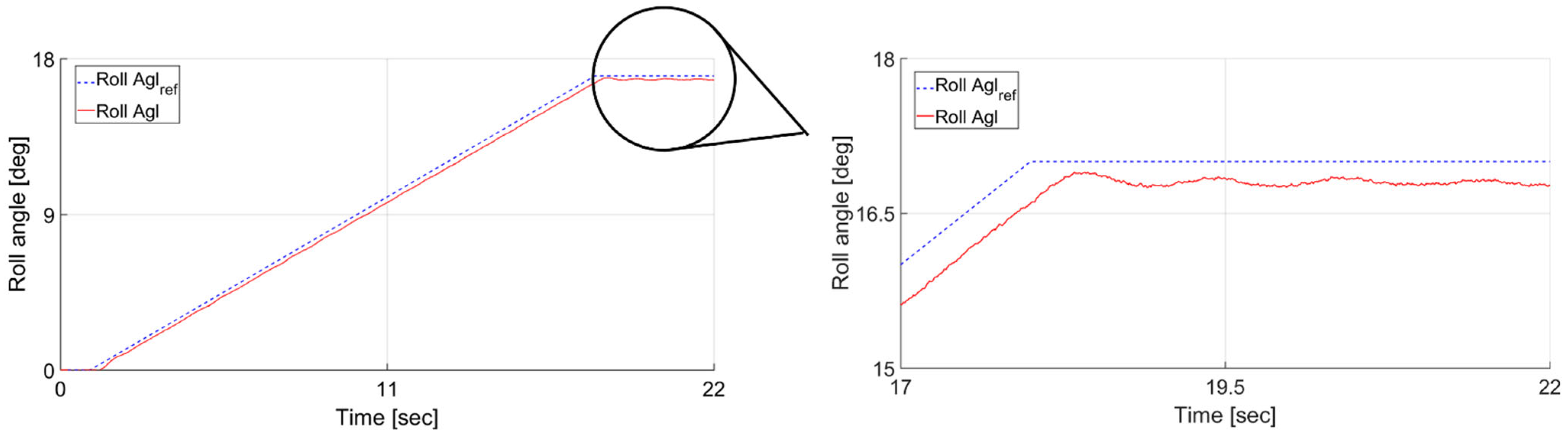
3.1. Roll Direction Reshape Experiment Result

We conducted experimental tests of the roll direction reshape result for the forming robot. An angular graph of the roll direction is shown in Figure 8. The angular input of the forming robot for the roll direction movement is represented by the solid line. The actual angle of the forming robot is shown by the dashed line. We apply an angular input as a slope function at a rate of 1°/s. In response, the forming robot accelerates for 18.3 s. At 19.4 s, the gripper platform decelerates. In the angular input, the goal is to achieve a 17.0° bending angle. As shown in Figure 8, the reshaped angle of the strip is measured, and the actual bending angle is 16.8°. The deviation between the input and output angles is due to the characteristics of the alloy strip’s elastic deformation. This experiment confirmed that the forming robot for internally fixed titanium alloy strips can reshape the alloy strip in the roll direction. The bending error range in roll direction is within ±0.2°.

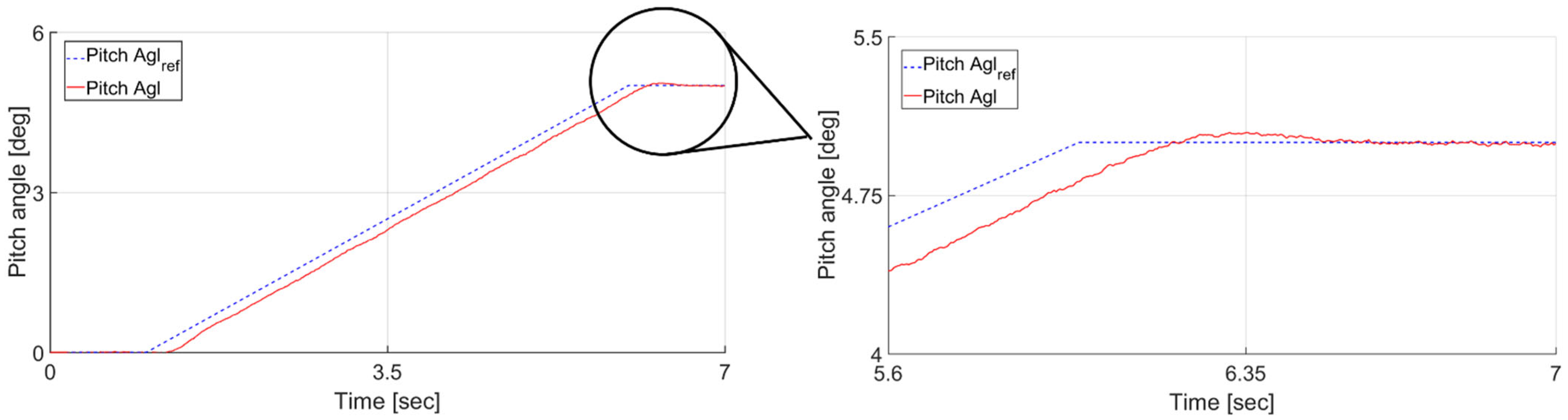
3.2. Pitch Direction Reshaping Result

The pitch direction strip bending experimental test was conducted, and Figure 9 shows the bending result of the motor encoder. We applied an angular input as a slope function at a rate of 1°/s. The goal was to achieve a 5° bending angle. After 0.29 s, it reaches the desired velocity, 1.0°/s. At 6.4 s, it decelerates. We proved that the forming robot for internally fixed titanium alloy strips can reshape the alloy strip in the pitch direction. The bending error range in pitch direction is within ±0.1°.

3.3. Yaw Direction Reshaping Result

The yaw direction strip bending experimental test is conducted, and Figure 10 shows the bending result of the motor encoder. We applied an angular input as a slope function at a rate of 1°/s. The goal was to achieve a 7° bending angle. After 0.26 s, it reaches the desired velocity, 1.0°/s. At 8.6 s, it decelerates. We proved that the forming robot for internally fixed titanium alloy strips can reshape the alloy strip in the yaw direction. The bending error range in yaw direction is within ±0.1°.

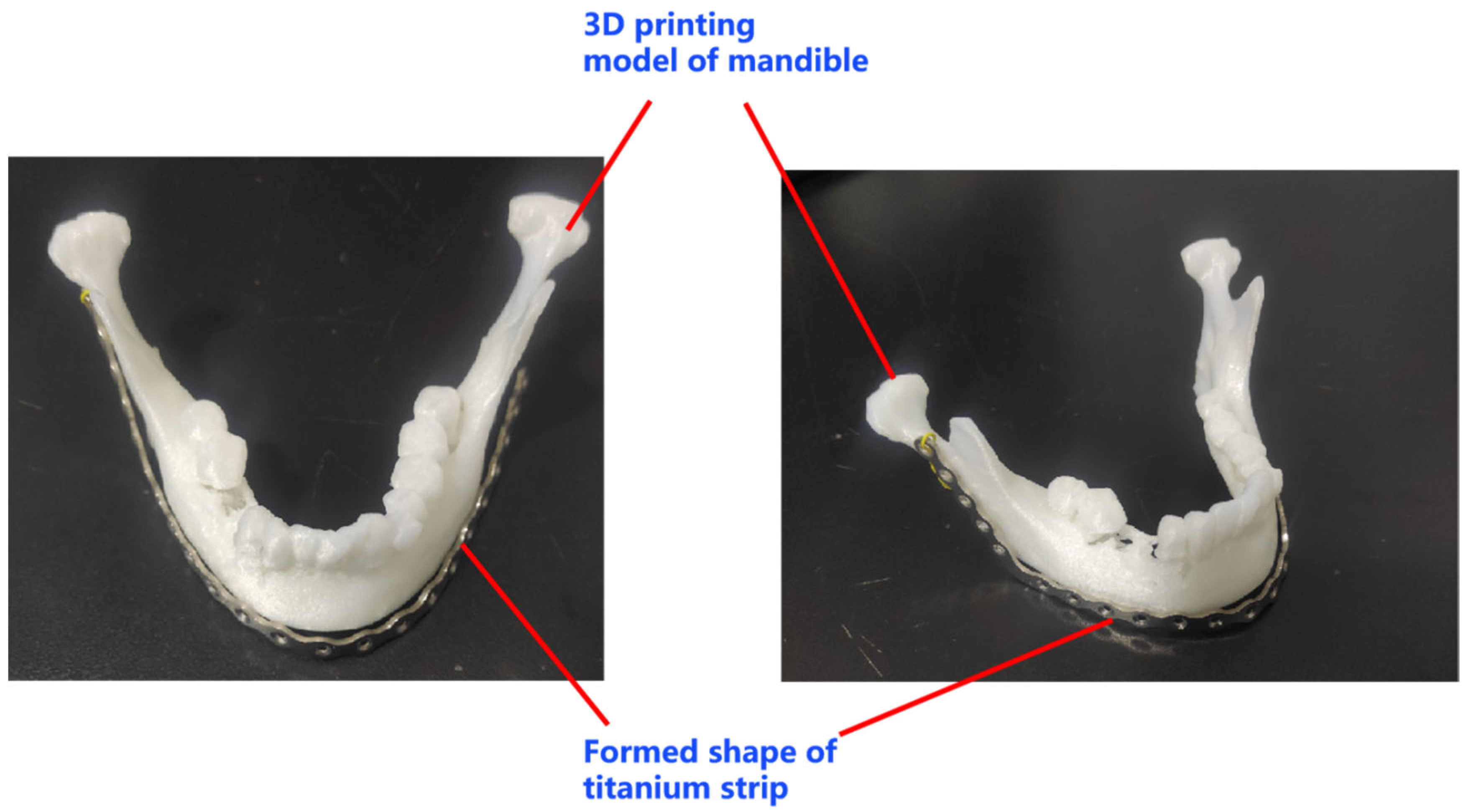
3.4. Overall Reshaped Titanium Alloy Strip Experiment

The purpose of the forming robot is to automatically reshape the initial titanium alloy strip to reduce the manual intervention of medical staff. Figure 11 shows the overall reshaped titanium alloy strip. In the experiment, a mandible model is scanned as a digital 3D model in the PC. Next, we simulate a proper form of strip to fit the mandible’s shape. Third, we calculate the forming angles for each strip hole. Lastly, the forming angles are programmed as input commands of the forming robot to reshape a titanium alloy strip. Figure 11 shows that the forming robot is capable of automatically reshaping a titanium strip to fit the mandible model. To estimate the error of the reshaped titanium alloy strip, we scan the overall reshaped titanium alloy strip and mandible model, import the digital models in a 3D software and match the models manually so that both of them fit closely. By measuring the maximum error of the two models, the error range is 4.3 mm.

4. Conclusions

Digital medicine has greatly improved the accuracy and speed of medical surgery. Titanium strip bending is the only process in digital maxillofacial surgery that has not been digitized and still requires manual operation. Developing a forming robot that can automatically and precisely bend titanium strips is the objective of this study.
In this study, a new design of an internally fixed strip forming robot is proposed. According to the mechanical characteristics of the processed titanium alloy strip, the motor parameters of the robot are checked, which provides a basis for motor selection. Development of the electrical control system is discussed, and three bending experimental tests are presented. The preliminary experimental results show that the titanium-strip-forming robot is capable of automatically reshaping an internally fixed titanium strip.
Since this robot is designed to automatically bend the internally fixed strip, it can reduce the manual intervention of medical staff. Another advantage of this robot is that automatic bending can reduce the failure rate of titanium alloy strip bending, hence reducing the cost of maxillofacial surgery. In future, the 3D model of the mandible can be obtained by scanning patients’ mandibles, and an advanced software algorithm can be developed to automatically match the unbent titanium alloy with the appropriate bending angle to fit the patient’s mandible model, then the robot proposed in this research can carry out bending processing. This method will realize the customized strip bending capability for patients’ mandibles.

Author Contributions

Conceptualization, Y.L.; methodology, J.Z.; software, J.Z.; validation, B.S., J.Z. and Y.L.; formal analysis, J.Z. and Y.L.; investigation, G.Z.; resources, Y.L.; writing—original draft preparation, J.Z.; writing—review and editing, G.F.; visualization and supervision, G.Z.; project administration, J.Z.; funding acquisition, Y.L. All authors have read and agreed to the published version of the manuscript.

Funding

This research was funded by Public Welfare Science and Technology Projects of Ningbo, grant number 20211JCGY020110; National Natural Science Foundation of China, grant number 81901065; Hunan Province Science, Technology Department (Key R&D Program, grant number 2022SK2048; Natural Science Fund, grant number 2018JJ3850); Hunan Health Commission Fund, grant number B2019192; The science and technology innovation Program of Hunan Province, grant number 2021RC2033.

Data Availability Statement

The original data contributions presented in the study are included in the article, and further inquiries can be directed to the corresponding authors.

Conflicts of Interest

The authors declare no conflict of interest.

References

  1. Zhang, C.X.; Yan, X.U.; Bai, X.J. Analysis and countermeasure of the complications after titanium-plate used oral and maxillofacial surgeries. J. Oral Sci. Res. 2015, 31, 814–816. [Google Scholar]
  2. Defranco, M.J.; Patterson, B.M. The floating shoulder. J. Am. Acad. Orthop. Surg. 2006, 14, 499–509. [Google Scholar] [CrossRef] [PubMed]
  3. Cole, P.A.; Gauger, E.M.; Schroder, L.K. Management of scapular fractures. JAAOS-J. Am. Acad. Orthop. Surg. 2012, 20, 130–141. [Google Scholar] [CrossRef] [PubMed] [Green Version]
  4. Hoenecke, H.R., Jr.; Hermida, J.C.; Hernandez, C.F.; D’Lima, D.D. Accuracy of CT-based measurements of glenoid version for total shoulder arthroplasty. J. Shoulder Elb. Surg. 2010, 19, 166–171. [Google Scholar] [CrossRef] [PubMed]
  5. Jiang, J.G.; Zhang, Y.D.; Wei, C.G.; He, T.H.; Liu, Y. A review on robot in prosthodontics and orthodontics. Adv. Mech. Eng. 2015, 7, 198748. [Google Scholar] [CrossRef] [Green Version]
  6. Rigelsford, J. Robotic bending of orthodontic archwires. Ind. Robot Int. J. 2004, 31. [Google Scholar] [CrossRef]
  7. Müller-Hartwich, R.; Jost-Brinkmann, P.G.; Schubert, K. Precision of implementing virtual setups for orthodontic treatment using CAD/CAM-fabricated custom archwires. J. Orofac. Orthop. Fortschr. Der Kieferorthopädie 2016, 77, 1–8. [Google Scholar] [CrossRef] [PubMed]
  8. Gilbert, A. An in-office wire-bending robot for lingual orthodontics. J. Clin. Orthod. 2011, 45, 230. [Google Scholar] [PubMed]
  9. Liu, Y. Application of digital manufacturing technology to orthodontics. Chin. J. Stomatol. 2012, 5, 261–266. [Google Scholar]
  10. Zhang, Y.; Jia, Y. The control of archwire bending robot based on MOTOMAN UP6. In Proceedings of the 2009 2nd International Conference on Biomedical Engineering and Informatics, Tianjin, China, 17–19 October 2009. [Google Scholar]
  11. DU Hai-Yan, G.U.; Zhang, Y.D.; Liu, Y. Trajectory Planning of Archwire Bending Robot. China Mech. Eng. 2010, 21, 1605. [Google Scholar]
  12. Jiang, J.G.; Zhang, Y.D.; Zhou, K.; Jiang, J.X. Structure design of archwire bending robot for orthodontic treatment. In Proceedings of the 8th International Forum on Strategic Technology, Ulaanbaatar, Mongolia, 28 June–1 July 2013; pp. 696–699. [Google Scholar]
  13. Jiang, J.G.; Zhang, Y.D.; Jin, M.L.; Wei, C.G. Bending process analysis and structure design of orthodontic archwire bending robot. Int. J. Smart Home 2013, 7, 345–352. [Google Scholar] [CrossRef]
  14. Zhang, Y.; Jiang, J. Study on precise acceleration/deceleration planning of archwire bending robot. ICIC Express Lett. 2013, 7, 73–78. [Google Scholar]
  15. Zhang, Y.D.; Wei, C.G.; Jiang, J.G.; Jiang, J.X.; Liu, Y.; Wang, Y. Motion planning for archwire bending robot in orthodontic treatments. Int. J. Control. Autom. 2014, 7, 287–297. [Google Scholar]
  16. Zhang, X.; Lu, C.C.; Zhao, Z.F.; Zhong, J. Establishment and research on Springback mathematical model of wire roll bending process. Qinggong Jixie Light Ind. Mach. 2010, 28, 60–65. [Google Scholar]
  17. Zhang, Y.D.; Jiang, J.X. Analysis and experimental study of bending property of orthodontic archwire. China Mech. Eng. 2011, 22, 1827–1831. [Google Scholar]
  18. Jiang, J.G.; Ma, X.F.; Zhang, Y.D.; Liu, Y.; Hu, B. Springback mechanism analysis and experimentation of orthodontic archwire bending considering slip warping phenomenon. Int. J. Adv. Robot. Syst. 2018, 15. [Google Scholar] [CrossRef]
  19. Jiang, J.G.; Ma, X.F.; Zuo, S.H.; Zhang, Y.D.; Liu, Y. Digital expression and interactive adjustment method of personalized orthodontic archwire for robotic bending. J. Adv. Mech. Des. Syst. Manuf. 2019, 13. [Google Scholar] [CrossRef]
Figure 1. (a) 3D model of Bending and Forming Robot: overall view. (b) 3D model of Bending and Forming Robot: upper half part.
Machines 10 00068 g001
Figure 2. Robot movement along each DOF: (a) initial state, (b) movement along the roll direction, (c) movement along the direction, (d) movement along the yaw direction.
Machines 10 00068 g002
Figure 3. The position of the bending origin point.
Machines 10 00068 g003
Figure 4. System communication framework.
Machines 10 00068 g004
Figure 5. Overall control system architecture of the forming robot.
Machines 10 00068 g005
Figure 6. (a) Overall experimental device of the forming robot. (b) Zooming in on the top of the forming robot.
Machines 10 00068 g006
Figure 7. The flowchart of the forming robot operation.
Machines 10 00068 g007
Figure 8. Roll direction bending response.
Machines 10 00068 g008
Figure 9. Pitch direction bending response.
Machines 10 00068 g009
Figure 10. Yaw direction bending response.
Machines 10 00068 g010
Figure 11. Overall reshaped titanium alloy strip.
Machines 10 00068 g011
Table 1. Mechanical properties of titanium alloy at room temperature.
Mechanical Properties of Titanium AlloyValues
Type CompositionTC4
CompositionTi6Al4V
Strip thickness (mm)3
Tensile strength δb (MPa)895
Yield strength δs (MPa)860
Elastic limit δb (MPa)967
Table 2. Geometric parameter of the titanium alloy strip.
Geometric Parameter of the Titanium Alloy StripValues
Length (/mm)13
Width (/mm)6
Thickness (/mm)3
Table 3. Specifications of the motor and gear.
ObjectParameterConfiguration
Motor for roll and pitchTypeST8N40P
Nominal Voltage (V)24
Nominal Output (N·m)0.32
Motor for yawTypeST8N60P
Nominal Voltage (V)24
Nominal Output (N·m)0.64
Harmonic GearSize20
Reduction Ratio50:1
Allowable Max Momentary Torque (N·m)35
SizeST8N40P
Table 4. Specification of the target PC BOXER-6639.
Specification of the Target PCConfiguration
CPUIntel i5-6500TE
CLOCK2300 MHz
RAM4 GB
UART6-Channel
Ethernet2 × LAN
MemoryCFCard
Publisher’s Note: MDPI stays neutral with regard to jurisdictional claims in published maps and institutional affiliations.

