
Analysis of the Influence of Thermophysical Properties of a Droplet Liquid on the Work Processes of a Two-Stage Piston Hybrid Power Machine


Abstract
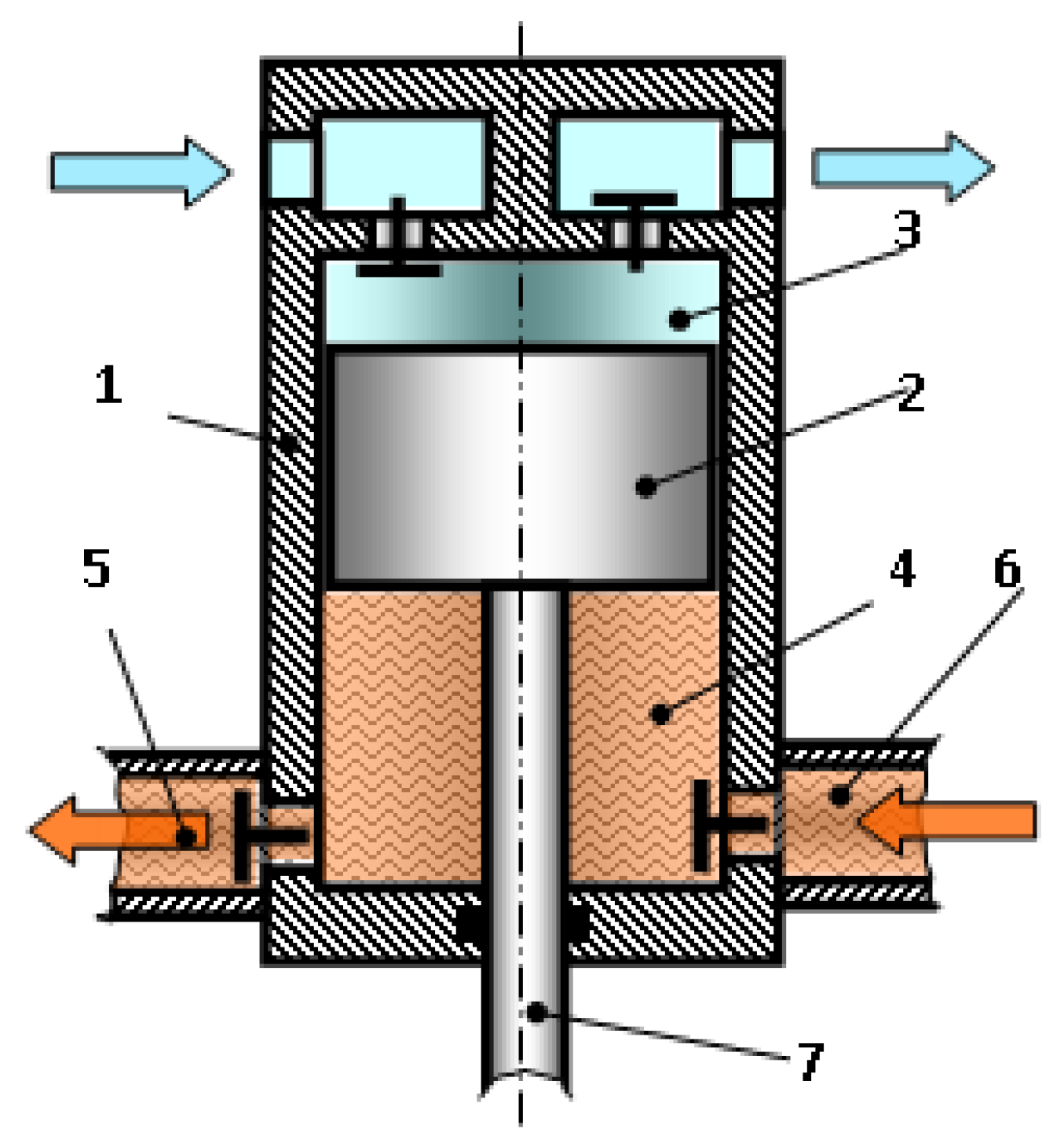
:1. Introduction
2. Theoretical Research
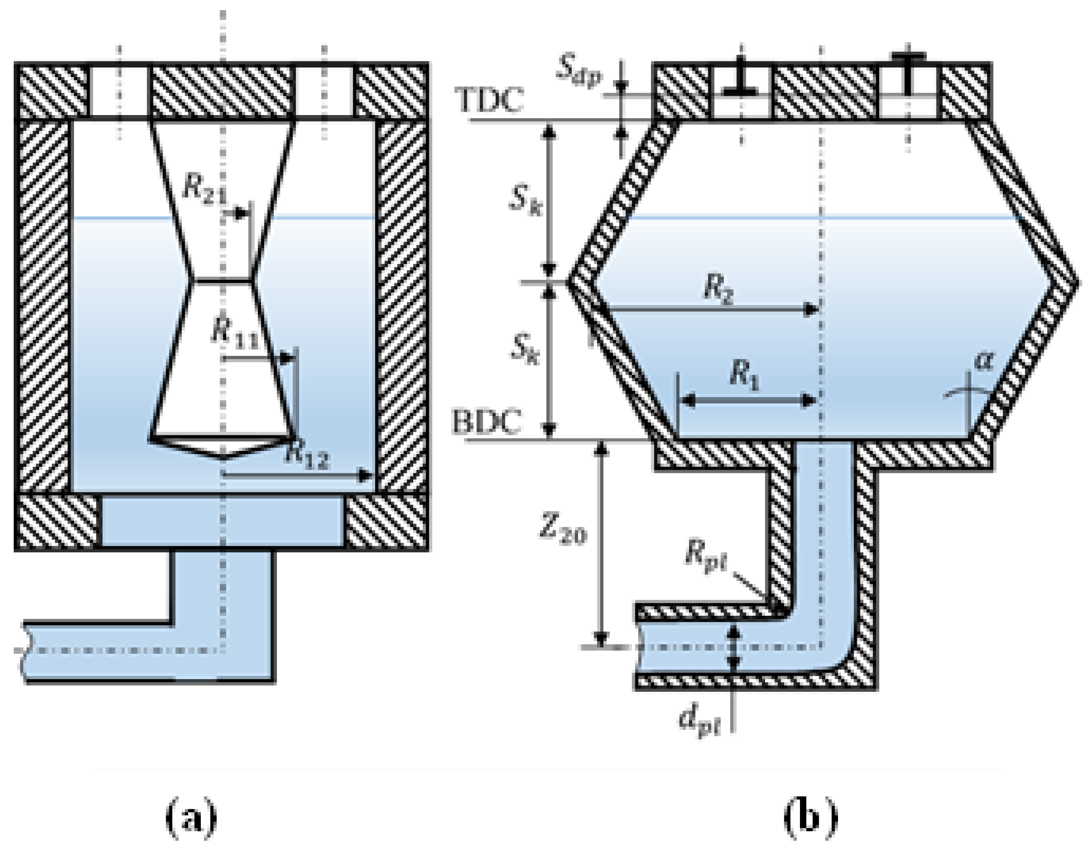
2.1. Determination of Basic Geometric Parameters
2.1.1. Determination of Working Chamber of Stage 2
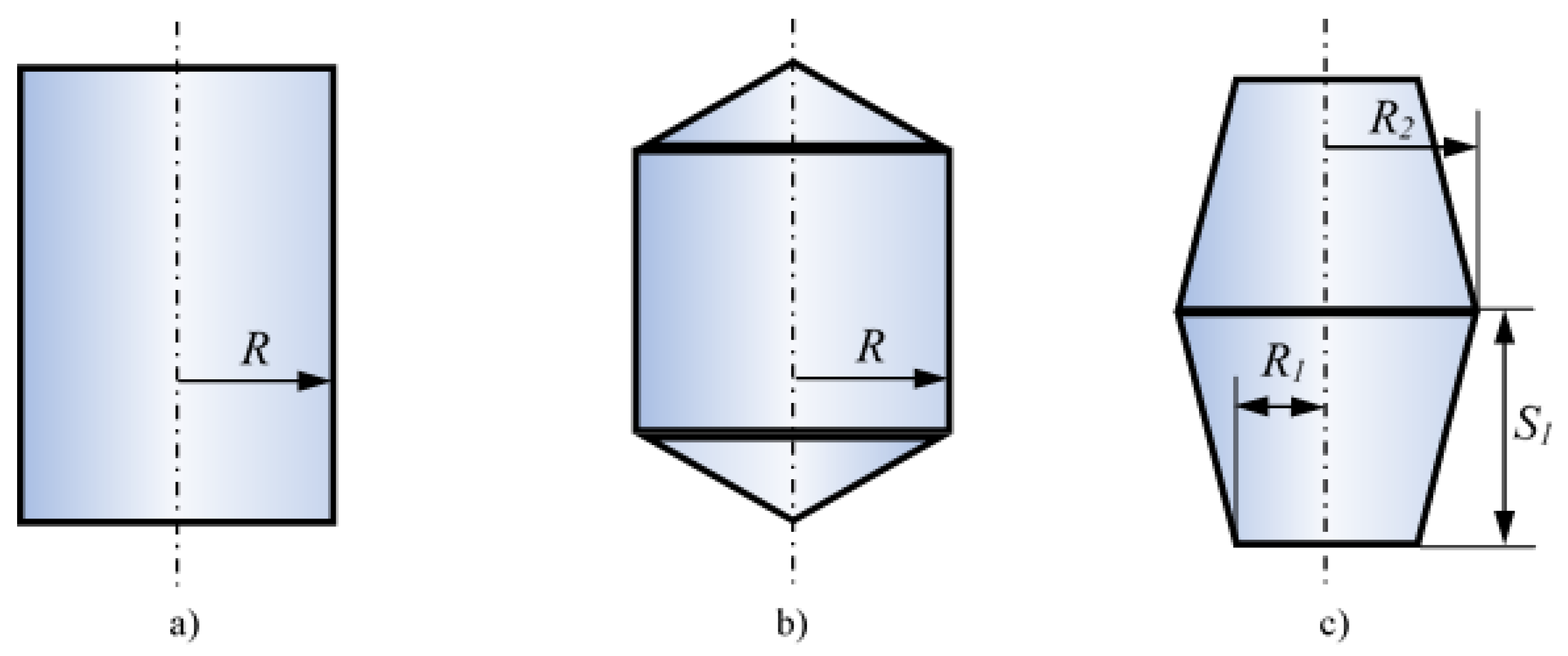
2.1.2. Profiling of Stage 2 Working Chamber
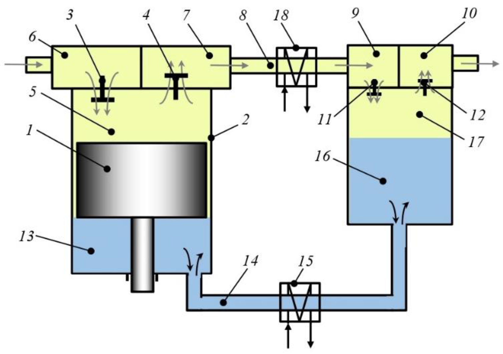
2.2. Review of Mathematical Models and System of Accepted Assumptions
- for the chambers of the compressor section: the first law of thermodynamics of a body of variable mass, the equation of conservation of mass, the equation of volume change, the equation of state, the equation of the dynamics of motion of the closure body of the self-acting valve;
- for the working chamber of the pump section: the energy conservation equation written in the form of the Bernoulli equation; Hooke’s equation, volume conservation equation, mass conservation equation. In [24,25], a general approach was developed for calculating work processes in the working chamber of a compressor and a positive displacement pump.
- taking into account the above, we accept a mathematical model with lumped parameters to simulate the working processes of a two-stage PHPM;
- taking into account that the mathematical models of the working processes of single-stage cross-head and crosshead-free PHPMs are well developed, we consider the working processes in stage 2 of the PHPM and the liquid movement from the pump section of stage 1 through the connecting pipeline to stage 2;
- the thermodynamic gas parameters in stage 2 suction chamber are constant and equal to their rated values;
- the motion of the liquid at each moment of time is steady and stationary, i.e., the motion of the liquid is quasi-stationary;
- the working liquid has constant temperature and follows Newton’s laws;
- the thermophysical properties of the liquid are constant;
- coefficients of friction along the length and local coefficients of resistance obtained for stationary conditions are also valid for unsteady flow;
- the bottom of the liquid piston is a plane parallel to the ground;
- there is no droplet liquid in the compressed gas in stage 2 of the PHPM;
- compressed gas follows the laws that are true for an ideal gas;
- the simulated processes in a compressible gas are equilibrium and reversible;
- the change in kinetic and potential energy for a compressible gas can be neglected.
- the movement of the closure body of a self-acting valve is considered as the movement of a material point;
- the walls of the pipeline and working chambers are considered absolutely rigid.
2.3. Mathematical Model of the Working Processes of a Two-Stage PHPM
- the height of the surface of the liquid piston is less than the height of the truncated cone (S1), then . Value z21 is determined from the solution of the following nonlinear volume conservation equation
- the surface of the liquid piston is greater than the height of the truncated cone (S1), then . Value z22 is determined from the equation of conservation of the liquid volume
- for the diffusorwhere is diffuser expansion ratio; is liquid velocity in the initial section of the diffuser.
- for the confusorwhere is the degree of narrowing of the confuser; is liquid velocity in confuser.
- local resistance when connecting stage 1 pumping section to connecting pipeline 3—sudden narrowing ();
- local resistance when flow turns ();
- local resistance when connecting pipeline 3 to the working chamber of stage 2—sudden expansion ();
- constant expansion in the diffuser part of the working chamber and constant narrowing in the confuser part of the working chamber .
- At z2i < S1 the inertial head losses are determined as:where ; ; .
- At z2i > S1where, .
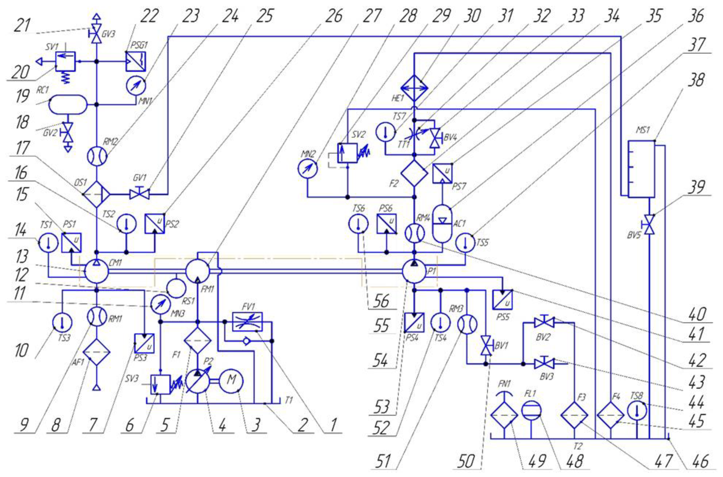
3. Experimental Studies
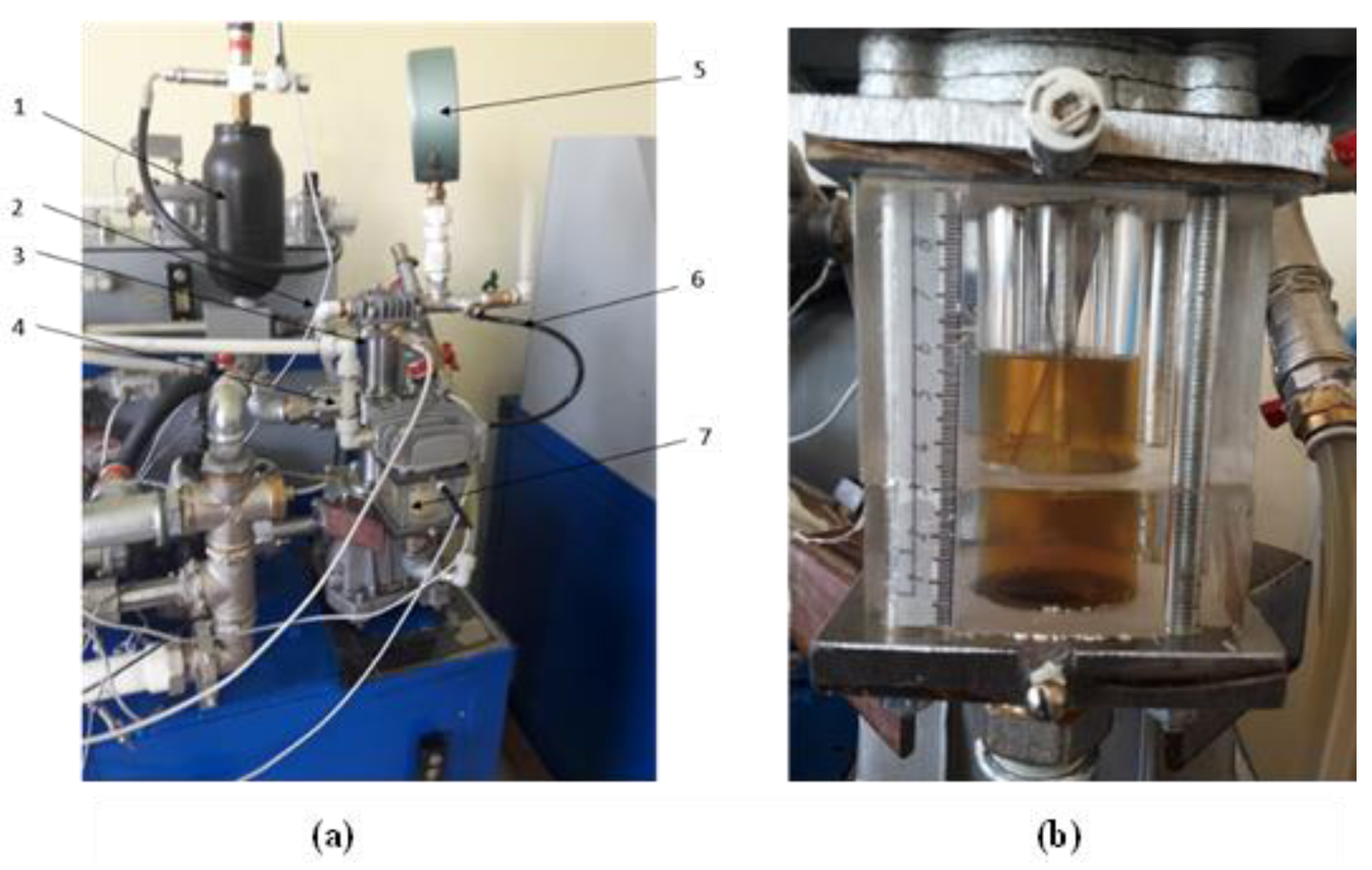
3.1. Subject of Research, Stand, and Measuring Equipment
3.2. Verification of the Mathematical Model of Work Processes
4. Results of a Numerical Experiment and Their Discussion
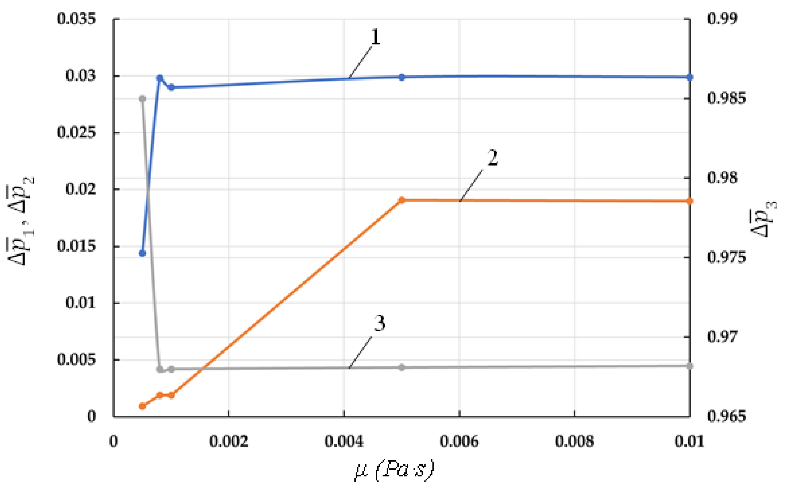
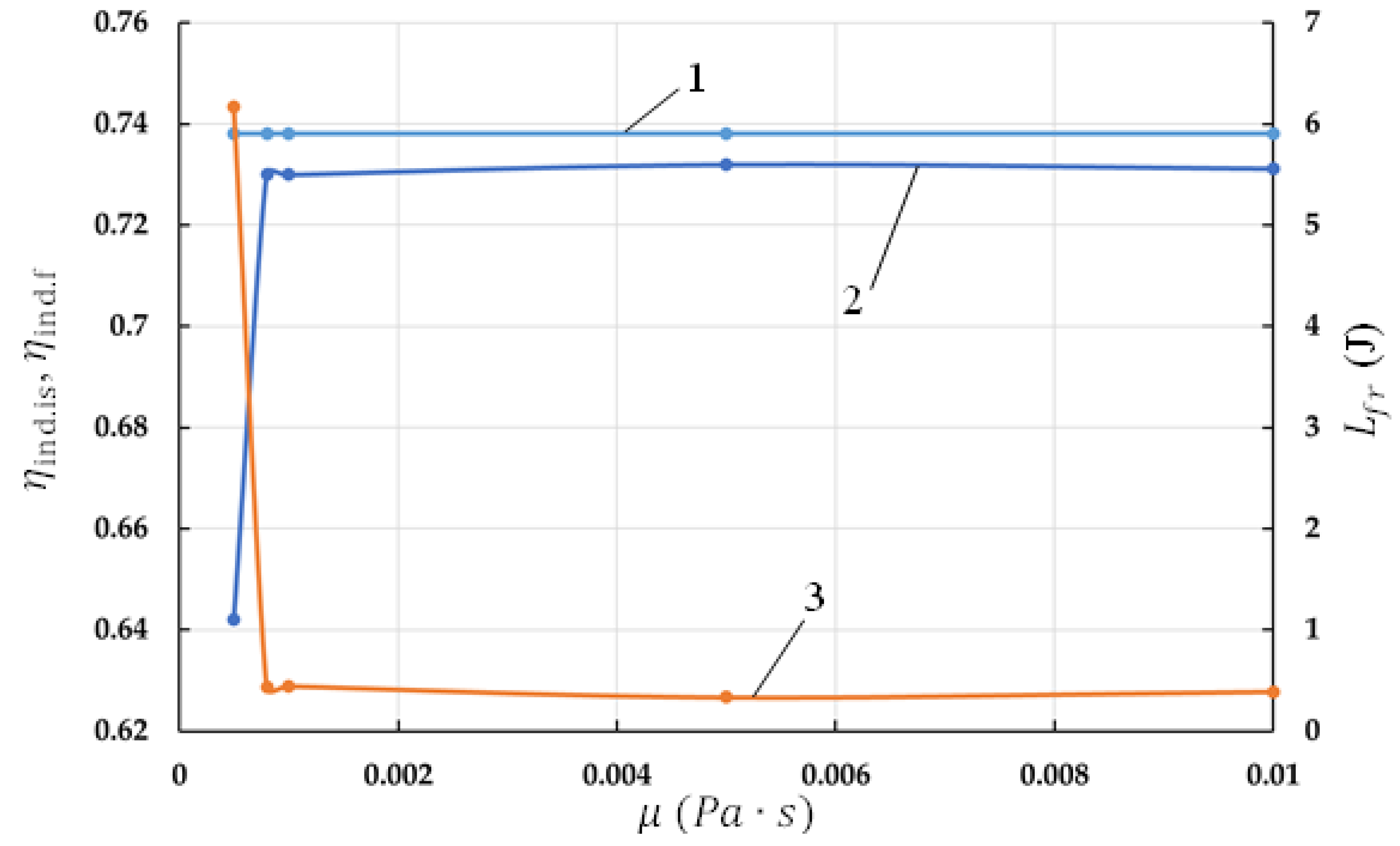
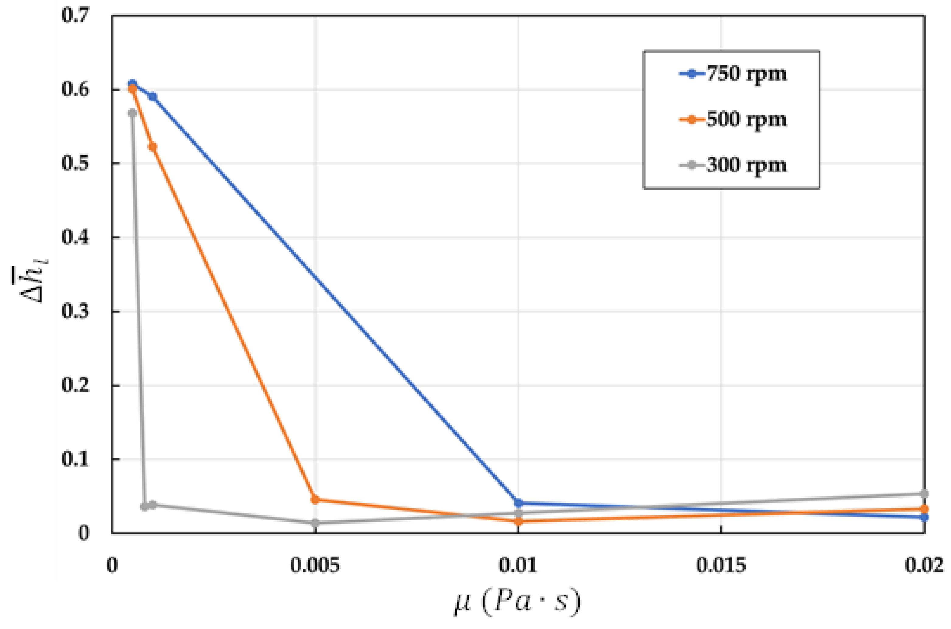
4.1. Analysis of the Influence of the Coefficient of Dynamic Viscosity
4.2. Influence of the Angular Velocity of the Crankshaft
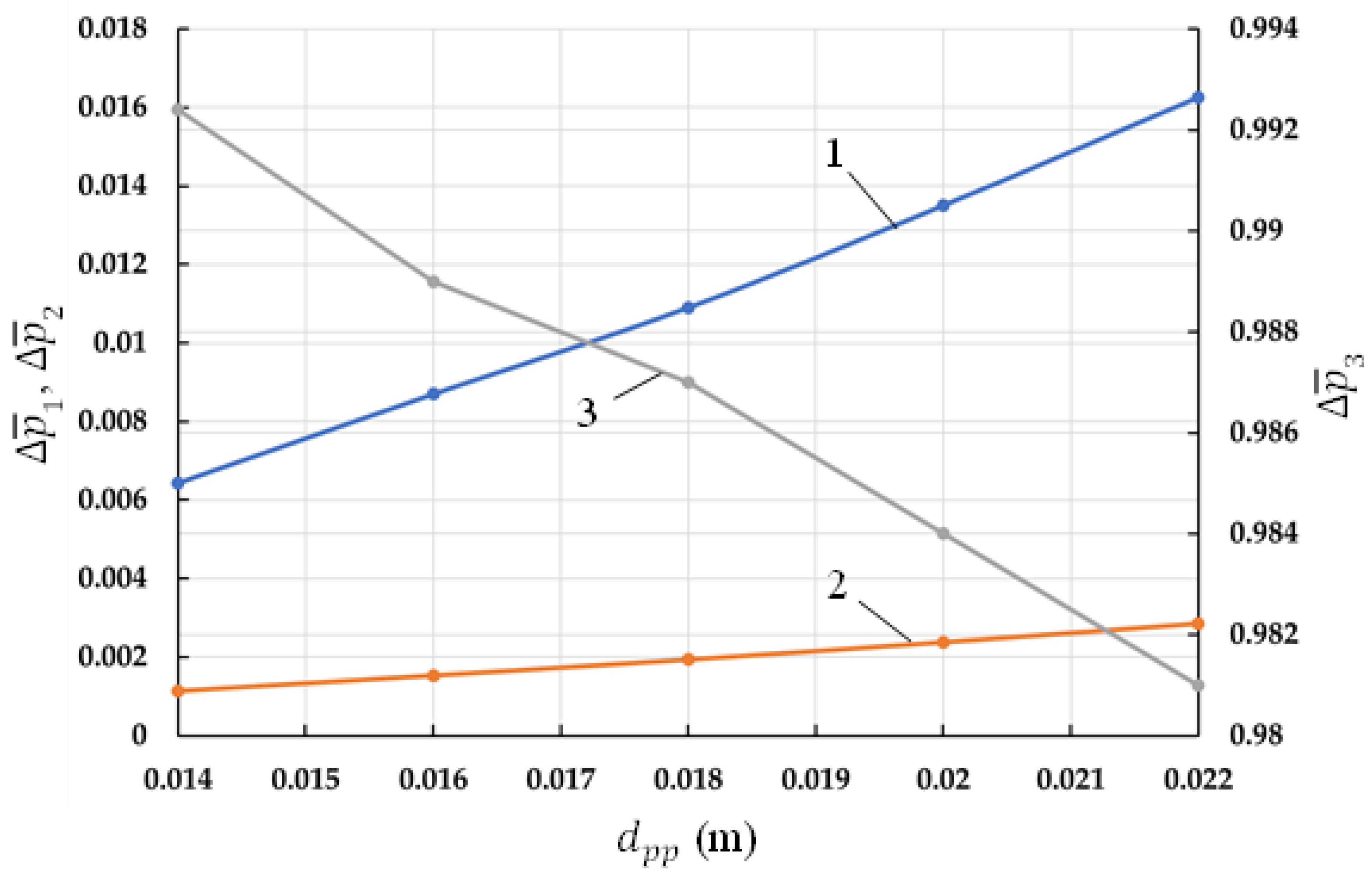
4.3. Influence of the Diameter of the Connecting Pipe
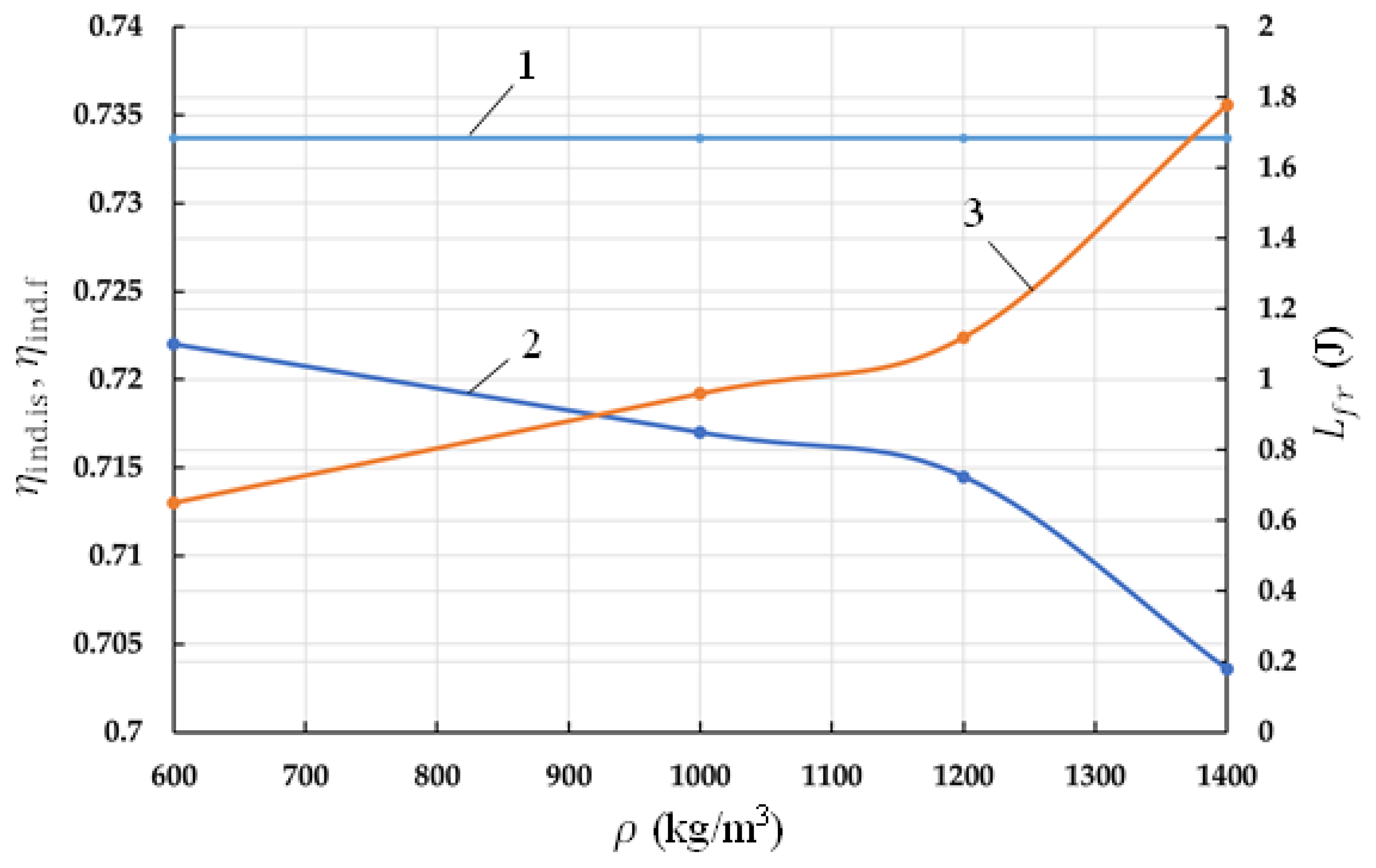
4.4. Analysis of the Effect of Liquid Density
5. Conclusions
- (1)
- There is a value of the optimal value μw, which provides the maximum value of the total indicator efficiency and bypassing the work of the forces of liquid friction. The optimal μw is in the range from 0.005 Pa∙s to 0.02 Pa∙s, with a change in the number of revolutions of the crankshaft from 300 rpm to 750 rpm.
- (2)
- With an increase in the angular velocity of the crankshaft to obtain maximum efficiency, it is necessary to increase the dynamic viscosity coefficient. The use of water as a coolant is not effective, because as the temperature rises, it decreases and at the operating temperature T = 323 K; its value is μw = 0.0005494 Pa∙s, which corresponds to the minimum indicator efficiency and the maximum work of friction forces. An increase in the diameter of the connecting pipeline leads to a decrease in the work of friction forces and an increase in the indicator efficiency.
- (3)
- With a decrease in the density of the medium, the total indicator isothermal efficiency increases and the work of friction forces decreases. The minimum relative hydraulic losses along the length and the maximum and correspond to ρw = 1200 kg/m3.
- (4)
- The analysis showed that industrial oil I-12A, which has ρw = 880 kg/m3 and μw/ρw = (13÷17)∙10−6 m2/s can be used as power liquid in the machines.
Author Contributions
Funding
Informed Consent Statement
Conflicts of Interest
Nomenclature
| angle between the generatrix of the cone and the height; | |
| coriolis coefficient for Section 1; | |
| coriolis coefficient for Section 2; | |
| heat transfer coefficient of compressible gas; | |
| coefficient of volume compressibility; | |
| coefficient of temperature expansion; | |
| head loss due to inertial resistance in stage 1 of the pump section; | |
| head loss due to inertial resistance in the working chamber of stage 2; | |
| head loss due to inertial resistance in the pipeline; | |
| head loss along the length in the cylinder of stage 1 pumping section; | |
| head loss along the length in the working chamber of stage 2; | |
| head loss along the length in connecting pipeline 3; | |
| pressure loss in the interstage connecting of the compressor section; | |
| undercooling value of gas sucked into stage 2 of the compressor section; | |
| Δpc | the ratio of the discharge pressure to the suction pressure of stage 1; |
| ΔTH0 | flow rates in stages 1 of the compressor section; |
| ε1 | flow rates in stages 2 of the compressor section; |
| λ1 | ratio of piston stroke to twice the length of the connecting rod; |
| λ2 | coefficient of friction along the length in the cylinder of stage 1; |
| λm | coefficient of friction along the length in the working chamber of stage 2; |
| coefficient of friction along the length in the connecting pipe; | |
| dynamic viscosity; | |
| liquid density; | |
| sum of forces acting on the valve closure; | |
| crankshaft angle; | |
| piston acceleration; | |
| φ | acceleration in the connecting pipeline; |
| stage 1 cylinder diameter; | |
| elementary time interval; | |
| connecting pipe diameter; | |
| elementary i:th separable mass of gas; | |
| elementary i:th attached mass of gas; | |
| dM0i | rod diameter in PHPM stage 1; |
| dMni | elementary heat input; |
| dr | stage 1 mechanical piston area; |
| dQg | working chamber lateral surface area; |
| heat exchange surface; | |
| piston surface area; | |
| valve plate area; | |
| cross-sectional area; | |
| gravity acceleration; | |
| mass of gas supplied to the discharge line; | |
| g | head loss on local resistance; |
| degree of valve closure lift; | |
| inertial head losses; | |
| hc | head loss along the length; |
| specific enthalpy of the separated gas mass; | |
| specific enthalpy of the added i:th mass of gas; | |
| i0 | adiabatic exponent; |
| ini | connecting pipe length; |
| k | reduced mass of the self-acting valve closure; |
| number of sources of separated and attached gas masses; | |
| mrdv | pressure in stage 1 of discharge chamber; |
| N1, N2 | gas pressure; |
| gas pressure at the suction of stage 1 of the compressor section; | |
| gas pressure at the suction of stage 2 of the compressor section; | |
| psc1 | liquid pressure; |
| psc2 | liquid flow; |
| small radius of the truncated cone; | |
| large truncated cone radius; | |
| truncated cone height; | |
| piston stroke; | |
| piston stroke in PHPM stage 1; | |
| linear dead space; | |
| Sh1 | average integral temperature of the lateral surface of the working chamber; |
| temperature of the compressible gas; | |
| suction gas temperature in stage 1 of the compressor section; | |
| suction gas temperature in stage 2 of the compressor section; | |
| Tsc1 | mean integral temperature of the valve plate surface; |
| Tsc2 | mean integral temperature of the surface of the compression chamber; |
| total internal energy of the compressible gas; | |
| mechanical piston speed in stage 1 pumping section; | |
| gas volume; | |
| the working volume of the pumping section of stage 1; | |
| working volume of stage 1 of the compressor section; | |
| working volume of stage 2 of the compressor section; | |
| liquid velocity in the connecting line; | |
| suction gas volume in stage 1 of the compressor section; | |
| suction gas volume in stage 2 of the compressor section; | |
| liquid velocity; | |
| coordinate of the gravity center of the first cross-section; | |
| coordinate of the gravity center of the second cross-section; | |
| distance from the axis of connecting pipeline 3 to the lower surface of the working chamber of stage 2; | |
| coordinate of the surface of the liquid piston; | |
| distance from the surface of O-O cross-section to the surface of the liquid piston; | |
| the coordinate of the gravity centers of the cross-sections; |
References
- Abdel-Hadi, A.; Salem, A.R.; Abbas, A.I.; Qandil, M.; Amano, R.S. Study of energy saving analysis for different industries. J. Energy Resour. Technol. Trans. ASME 2021, 143, 052101. [Google Scholar] [CrossRef]
- Silva, E.; Dutra, T. Piston trajectory optimization of a reciprocating compressor. Int. J. Refrig. 2021, 121, 159–167. [Google Scholar] [CrossRef]
- Yan, B.; Wieberdink, J.; Shirazi, F.; Li, P.Y.; Simon, T.W.; Van de Ven, J.D. Experimental study of heat transfer enhancement in a liquid piston compressor/expander using porous media inserts. Appl. Energy 2015, 154, 40–50. [Google Scholar] [CrossRef]
- Dindorf, R. Estimating Potential Energy Savings in Compressed Air Systems. Procedia Eng. 2012, 39, 1877–7058. [Google Scholar] [CrossRef] [Green Version]
- Ueno, K.; Hunter, K.S. Compressor Efficiency Definitions; University of Colorado: Boulder, CO, USA, 2003. [Google Scholar]
- Shcherba, V.E.; Paramonov, A.M.; Blinov, V.N.; Surikov, V.I.; Nosov, E.Y.; Tegzhanov, A.S. Comparative analysis of process of cooling of compressible gas in crosshead and crossheadless hybrid positive-displacement piston power machines. Chem. Pet. Eng. 2020, 55, 733–742. [Google Scholar] [CrossRef]
- Seshaiah, N.; Sahoo, R.K.; Sarangi, S.K. Theoretical and experimental studies on oil injected twin-screw air compressor when compressing different light and heavy gases. Appl. Therm. Eng. 2010, 30, 327–339. [Google Scholar] [CrossRef]
- Vittorini, D.; Cipollone, R. Energy saving potential in existing industrial compressors. Energy 2016, 102, 502–515. [Google Scholar] [CrossRef]
- Qv, D.; Dong, B.; Cao, L.; Ni, L.; Wang, J.; Shang, R.; Yao, Y. An experimental and theoretical study on an injection-assisted air-conditioner using R32 in the refrigeration cycle. Appl. Energy 2017, 185, 791–804. [Google Scholar] [CrossRef]
- Wang, X.; Hwang, Y.; Radermacher, R. Two-stage heat pump system with vapor-injected scroll compressor using R410A as a refrigerant. Int. J. Refrig. 2009, 32, 1442–1451. [Google Scholar] [CrossRef]
- Plastinin, P.I. Reciprocating Compressors; Tom 1: Moscow, Russia, 2006; 456p. [Google Scholar]
- Shcherba, V.E.; Bolshtyanskii, A.P.; Kaigorodov, S.Y.; Kuzeeva, D.A. Benefits of Integrating Displacement Pumps and Compressors. Russ. Eng. Res. 2016, 36, 174–178. [Google Scholar] [CrossRef]
- Zhang, C.; Li, P.Y.; van de Ven James, D. Design analysis of a liquid-piston compression chamber with application to compressed air energy storage. Appl. Therm. Eng. 2016, 101, 704–709. [Google Scholar] [CrossRef] [Green Version]
- Patil, V.C.; Acharya, P.; Ro, P.I. Experimental investigation of heat transfer in liquid piston compressor. Appl. Therm. Eng. 2019, 146, 169–179. [Google Scholar] [CrossRef]
- ToroK, A.; Petrescu, S.; Popescu, G. Quasi-Izothermal Compressors and Expanders with Liquid Piston. Available online: https://hal.archives-ouvertes.fr/hal-02461111/document (accessed on 16 January 2022).
- Piya, C.; Sircar, I.; Van de Ven James, D.; Olinger, D.J. Numerical Modeling of Liquid Piston Gas Compression. In Proceedings of the ASME International Mechanical Engineering Congress and Exposition, Lake Buena Vista, FL, USA, 13–19 November 2009; pp. 507–517. [Google Scholar]
- Kermani, N.A.; Rokni, M. Heat transfer analysis of liquid piston compressor for hydrogen applications. Int. J. Hydrog. Energy 2015, 40, 11522–11529. [Google Scholar] [CrossRef] [Green Version]
- Zhang, C.; Yan, B.; Wieberdink, J. Thermal analysis of a compressor for application to compressed air energy storage. Appl. Therm. Eng. 2014, 73, 1402–1411. [Google Scholar] [CrossRef]
- Saadat, M.; Li, P.Y.; Sirnon, T.W. Optimal trajectories for a liqu.id piston compressor/expander in a compressed air energy storage system with consideration of heat transfer and friction. In Proceedings of the American Control Conference (ACC), Montréal, QC, Canada, 27–29 June 2012; IEEE: Piscataway, NJ, USA, 2012; pp. 1800–1805. [Google Scholar]
- Shcherba, V.E.; Zanin, A.V.; Khrapskii, S.F. Fluid motion dynamics in a two-stage piston hybrid power machine. Chem. Pet. Eng. 2020, 56, 534–542. [Google Scholar] [CrossRef]
- Shcherba, V.E.; Shalai, V.V.; Pustovoi, N.; Zanin, A.V. On Profiling of the Working Cavity of the Second Stage in a Hybrid Piston Volumetric Power Machine. Chem. Pet. Eng. 2020, 56, 125–136. [Google Scholar] [CrossRef]
- Vimmr, J. Mathematical modelling of compressible inviscid fluid flow through a sealing gap in the screw compressor. Math. Comput. Simul. 2003, 61, 187–197. [Google Scholar] [CrossRef]
- James, D.; Van de Ven Perry, Y.L. Liquid piston gas compression. Appl. Energy 2009, 86, 2183–2191. [Google Scholar] [CrossRef]
- Xu, W.; Du, Z.; Wang, X.; Cai, M.; Jia, G.; Shi, Y. Isothermal piston gas compression for compressed air energy storage. Int. J. Heat Mass Transf. 2020, 155, 119779. [Google Scholar] [CrossRef]
- Bradshaw, C.R.; Groll, E.A.; Garimella, S.V. A comprehensive model of a miniature-scale linear compressor for electronics cooling. Int. J. Refrig. 2011, 34, 63–73. [Google Scholar] [CrossRef] [Green Version]
- Kundu, P.K.; Cohen, I.M.; Dowling, D.R. Fluid Mechanics; Academic Press: London, UK, 2015. [Google Scholar]
- Zanin, A.; Pavlyuchenko, E.A.; Shcherba, V.E. Numerical and experimental study on fluid compressibility in a two-stage reciprocating pump-compressor. Appl. Therm. Eng. 2021, 194, 117106. [Google Scholar] [CrossRef]


| Indicator Description | Values |
|---|---|
| The diameter of the first stage piston | dp = 0.050 m |
| Diameter of the rod of the first stage | dr = 0.036 m |
| Full stroke of the 1st stage piston | Sh = 0.050 m |
| Initial coordinate of the liquid in the second stage | Z20 = 0.100 m |
| Diameter of the supply pipeline | dsp = 0.016 m |
| The length of the supply pipeline | lp = 0.5 m |
| Linear dead space | Sd = 0.0025 m |
| Turning radius of the supply pipeline | Rp = 0.5 m |
| Indicator Description | Values |
|---|---|
| Maximum lift height of the shut-off element of the suction valve in the compressor section | hscvmax = 0.0015 m |
| The width of the passage in the seat of the suction valve of the compressor section | dscvc = 0.023 m |
| Spring stiffness of the suction valve in the compressor section | csscv = 3200 N/m |
| Maximum lift height of the shut-off element of the discharge valve in the compressor section | hdvmax = 0.0015 m |
| The width of the passage in the seat of the discharge valve of the compressor section | ddvc = 0.023 m |
| Spring stiffness of the discharge valve in the compressor section | csdv = 3200 n/m |
| Indicator Description | Values |
|---|---|
| The diameter of stage 1 piston | d1 = 0.050 m |
| Diameter of the stem of stage 1 | dst = 0.036 m |
| Full stroke of stage 1 piston | Sh1 = 0.050 m |
| The number of revolutions of the crankshaft | nrev = 500 rpm |
| Suction pressure | Psc2 = 5 × 10⁵ Pa |
| Discharge pressure | Pd2 = 25 × 105 Pa |
| The average temperature of the walls of the surface of the working chamber of stage 2 | = 330 K |
| Intake air temperature | Tsc2 = 310 K |
| Initial coordinate of the liquid in stage 2 | Z20 = 0.100 m |
| Diameter of the supply pipeline | dpp = 0.016 m |
| The length of the supply pipeline | lpp = 0.5 m |
| Linear dead space | Sds = 0.0025 m |
| Turning radius of the supply pipeline | Rpp = 0.5 m |
| The radius of the conical insert in the design scheme of stage 2 of the PHPM (see Figure 8) | R21 = 0.003 m, R11 = 0.015 m |
| The radii of the conical working chamber in the given design scheme of stage 2 of the PHPM: | R1 = 0.0132 m, R2 = 0.01977 m |
| The angle of inclination of the generatrix of the truncated cone | α = 0.235 rad |
| Truncated cone height | S1 = 0.0272 m |
| The maximum lifting height of the closure body of the discharge valve | hdmax = 0.001 m |
| The maximum lifting height of the closure body of the suction valve | hscmax = 0.001 m |
| The width of the passage in the saddle of the suction valve | dscv = 0.09 m |
| The width of the passage in the saddle of the discharge valve | ddv = 0.09 m |
| Spring rate of the discharge valve | Csprd = 16,280 N/m |
| Spring rate of the suction valve | Csprsc = 5980 N/m |
| Maximum clearance between the saddle and the closure body of the suction valve | δsc = 1 × 10⁻⁸ m |
| Minimum clearance between the saddle and the closure body of the discharge valve | δd = 1 × 10⁻⁸ m |
| Roughness of the inner surface of the connecting pipeline | K = 0.000005 m |
| Compressed gas | air |
Publisher’s Note: MDPI stays neutral with regard to jurisdictional claims in published maps and institutional affiliations. |
© 2022 by the authors. Licensee MDPI, Basel, Switzerland. This article is an open access article distributed under the terms and conditions of the Creative Commons Attribution (CC BY) license (https://creativecommons.org/licenses/by/4.0/).
Share and Cite
Shcherba, V.; Pavlyuchenko, E.; Nosov, E.; Bulgakova, I. Analysis of the Influence of Thermophysical Properties of a Droplet Liquid on the Work Processes of a Two-Stage Piston Hybrid Power Machine. Machines 2022, 10, 70. https://doi.org/10.3390/machines10020070
Shcherba V, Pavlyuchenko E, Nosov E, Bulgakova I. Analysis of the Influence of Thermophysical Properties of a Droplet Liquid on the Work Processes of a Two-Stage Piston Hybrid Power Machine. Machines. 2022; 10(2):70. https://doi.org/10.3390/machines10020070
Chicago/Turabian StyleShcherba, Victor, Evgeniy Pavlyuchenko, Evgeniy Nosov, and Irina Bulgakova. 2022. "Analysis of the Influence of Thermophysical Properties of a Droplet Liquid on the Work Processes of a Two-Stage Piston Hybrid Power Machine" Machines 10, no. 2: 70. https://doi.org/10.3390/machines10020070