Article

Calculating the Load Distribution and Contact Stress of the Disposable Harmonic Drive under Full Load

School of Mechatronics Engineering, Harbin Institute of Technology, Harbin 150001, China
*
Author to whom correspondence should be addressed.
Machines 2022, 10(2), 96; https://doi.org/10.3390/machines10020096
Submission received: 27 November 2021 / Revised: 20 January 2022 / Accepted: 24 January 2022 / Published: 26 January 2022
(This article belongs to the Section Machine Design and Theory)

Abstract

:
Mechanical equipment that will not be reused is defined as disposable machinery. Disposable harmonic drives (HDs) are commonly used in the field of aerospace and are sensitive to payloads. Reasonable calculation of the gear strength is essential for structural design. A method of calculating the contact characteristics of HDs under full load by combining a surface contact model with a three-dimensional finite element model (FEM) is proposed in this work. The mathematical model was established for calculating the no-load backlash of conventional and disposable harmonic gears after assembly. Afterward, the tooth load distribution and surface contact stress were determined using the Hertz contact theory. Finally, ABAQUS software was used to establish the FEM of the disposable HD, and the results were compared with those obtained from the theoretical model. The results revealed that the disposable harmonic gear can realize short-term transmission under full load.

1. Introduction

Conventional mechanical systems, equipment, or devices that are long-running and repeatedly used are referred to as conventional machinery. However, in some special instance, some kinds of machinery are abandoned after being used only once. This kind of machinery is defined as disposable machinery in this paper. This type of equipment always takes full load or short-time overload as the normal working conditions and has an extremely short service life (from a few minutes to a few dozen minutes). As the typical disposable machinery in the field of aerospace, disposable electric actuators often adopt the form of harmonic gear transmission. A harmonic gear drive is composed of three basic components—an internal tooth rigid wheel, an external tooth flexible wheel, and an elliptical wave generator assembled in the flexible wheel. The drive transmits motion and power through the radial periodic elastic deformation of the flexible wheel [1]. With the increasing demand for payloads in the aerospace industry, disposable harmonic gears that can be used under full load have gradually gained attention. The short-term ultimate carrying capacity and dynamic performance of disposable harmonic gears have become research hotspots [2]. Multiple teeth come into contact simultaneously in disposable HDs, and studies focused on the contact performance of disposable HDs are essential for ensuring the strength requirements.
Many papers have discussed the load distribution and stress associated with gear transmission. Harmonic gears adopt the straight tooth profile. In addition, harmonic gear transmissions also have the characteristics of a large number of simultaneous meshing teeth and a thin rim structure. Therefore, the research results on the contact performance of spur gears with a high contact ratio and thin rim can be referred to. Vivet [3] analyzed the contact characteristics of face-milled spiral bevel gears based on the beam theory and the Hertz contact theory. Thomas et al. [4] proposed a new coordinate system and search method to predict the tooth root bending stress in asymmetric spur gears. Using the Hertz contact principle and a finite element model (FEM), Mohammed et al. [5] determined the influence of rotational speed on the contact stress of spur gears. Wen et al. [6] established an improved model for calculating the contact stress of standard gears and tip-relieved gears based on the precise tooth profile equations. Many scholars [7,8,9,10] have researched the influence of a high contact ratio on the transmission performance of spur gears. Li [11,12] used a three-dimensional FEM to obtain the tooth load distribution and contact model of a thin-rimmed gear. The study found that the rim and web account for about 70% of the total thin-rimmed gear deformation, and the rim thickness has a significant influence on the stress. Ravivarman et al. [13] used an FEM to analyze the tooth load, contact stress, and tooth surface wear of a high contact ratio gear. Wang et al. [14] designed a new type of internal gear transmission with a high contact ratio. Compared to the traditional structure, the drive led to significant reductions in the contact stress and bending stress. Considering the time-varying mesh stiffness, gear backlash, static transmission error, and other parameters, Huang et al. [15] established a nonlinear dynamic model of a high contact ratio gear with multiple clearances. Jia et al. [16] proposed a tooth-profile modification scheme to reduce the contact stress and transmission error. Sun et al. [17] proposed a new parabolic profile modification method for a China bearing reducer and calculated the contact characteristics. Rama et al. [18] determined the tooth load-carrying capacity of the high contact ratio asymmetric gear drive using wire-cut electrical discharge machining. Huangfu et al. [19] evaluated the contact characteristics of thin-rimmed gear transmissions and performed tooth modification aimed at reducing surface wear.
In recent years, the contact model of conventional harmonic gears has been investigated. The deformation of the flexible wheel is the basis of the research on the contact characteristics of HDs. Ma et al. [20] established a dedicated micro-displacement platform with a pair of laser displacement sensors and analyzed the influence of driving speed on the deformation of the flexible wheel through experiments. Based on Ivanov’s empirical formula for the distribution of meshing force between gear teeth, Dong simplified the flexible wheel to a uniform thickness shell without gear teeth and calculated the deformation and stress on different sections of the flexible wheel [21]. He proposed an optimal design method for the involute tooth profile based on the meshing force given by the dynamic meshing simulation [22]. On the basis of the above research, Chen et al. [23] established a finite element model of the flexible wheel combining a variable cross-section shell element and a beam element and analyzed the deformation and stress of the flexible wheel under the combined action of the wave generator and the transmission torque [23]. Then, they studied the telescopic deformation of the neutral layer of the flexible wheel under the action of different wave generators [24,25]. Using an FEM, Kayabasi [26] studied the stress and strain of the flexible wheel in an HD, which can be used to determine the maximum stress and optimize the structure of a wheel. Chen [27] discussed the parametric design of a double circular-arc tooth profile and the influence on the backlash of the HD. The results of the study had instructive significance for the subsequent research on the contact strength of harmonic gears. Le [28] established the mechanical model of the flexible wheel and calculated the space dynamic meshing force of the harmonic flexible wheel according to the beam element theory. Zou [29] used the boundary conditions obtained from the empirical formula to establish a harmonic gear transmission face-contact FEM. The results revealed that the deformation and stress associated with the cross-section of the short flexible wheel change geometrically with increased load, but the distributions of the above two increments remained unchanged. Through an FEM, Sahoo [30] confirmed that the secondary contact of the tooth surface occurs in involute HDs. Routh [31] assessed the secondary tooth surface contact in involute harmonic gears based on the assumption of an elliptic cam and the occurrence of an ellipse pitch curve after assembly. Furthermore, Sahoo et al. [32] determined the load distribution associated with tooth pair contact in involute HDs. Yang et al. [33] analyzed the axial load of the flexible wheel in double circular-arc HDs and proposed methods for reducing the effect of the partial axial load. Sahoo et al. [34] combined an FEM and experiments to analyze the stress distribution of the flexible wheel in novel split-cam HDs.
Harmonic gear transmission has the characteristics of high precision, a large transmission ratio, small size, and light weight, and its basic design theory has evolved. Disposable machinery is an emerging concept. Compared to general harmonic gears, disposable harmonic gear transmissions for high-load operations have a higher power–weight ratio and an extremely low service life. At present, the research on harmonic gears is mainly oriented toward the requirements of conventional mechanical applications. Moreover, the research on the contact characteristics of disposable HDs is still in its infancy. Based on the research of thin rim spur gears and harmonic gears, the contact performance of disposable harmonic gear transmissions is discussed in this paper. Considering the cost and versatility of disposable machinery in disposable applications, the involute tooth profile with simpler processing technology was selected for this study. The rest of this paper is organized as follows. In Section 2, the mathematical model of no-load harmonic assembly is presented, and the no-load backlash curves of two types of HDs are discussed. In Section 3, the contact model of harmonic gears is established, and the load distribution of flexible wheels is calculated. Then, based on the load contribution, an analysis of the contact stress of two flexible wheels under full load is presented in Section 4. The finite element analysis of HDs for determining the contact characteristics of disposable harmonic gears is presented in Section 5, and the results are compared with the theoretical results. The conclusions of this study are summarized in Section 6.

2. Calculation of Backlash Generated for HDs with No Load

2.1. Design Scheme of Disposable Harmonic Gears

Harmonic drives are composed of three components—a flexible wheel, a rigid wheel, and a wave generator. Under conventional service conditions, after bearing alternating loads, the flexible wheel becomes the component to most prone fatigue failure in HDs. At present, the long cup flexible wheel structure is generally adopted in order to reduce the stress concentration at the bottom of the cup and prolong the service life. However, this structure cannot meet the requirements of the small size and light weight of disposable HDs. Considering that disposable harmonic gears have very high requirements for the ultimate carrying capacity and structural size, a straight cylinder flexible wheel with a complex wave harmonic drive was adopted in this study. The straight cylinder flexible wheel can be regarded as a thin-rimmed external gear, which has the characteristics of a simple structure and convenient processing. In addition, the smaller axial size can enable the harmonic drive to carry greater torque and reduce the torsional backlash caused by cylinder deformation. Therefore, the complex-wave HD structure is more suitable for full-load applications of disposable harmonic gears. The two types of flexible wheel structures are shown in Figure 1.
Compared to other structures, the elliptical cam wave generator ensures the good performance of HDs and is easily processed. Under the action of a wave generator, the middle plane of the flexible wheel will produce radial displacement ω(φ), circumferential displacement υ(φ), and axial displacement u(φ) at polar angle φ with no load after assembly. For the conventional harmonic drive, the axial displacement can be ignored (see Figure 2). However, the disposable flexible wheel does not include a cylindrical structure and the total length of the flexible wheel is equal to the tooth width. After assembly, the disposable flexible wheel is all contained within the width of the wave generator (φ1 = φ). Therefore, only the radial displacement can be considered after assembly for the disposable HD (see Figure 3).
Based on the elliptic characteristics, the polar coordinate of point H on the middle plane of the flexible wheel shell at polar angle φ can be expressed as follows [35]:
ρ ( φ ) = ( r m + ω 0 * m ) 2 4 r m ω 0 * m sin 2 φ
where rm represents the middle-plane radius of the flexible wheel rim, ω 0 * denotes the radial deformation coefficient of the flexible wheel, and m is the gear module.
The radial deformation of this point is
ω ( φ ) = ( r m + ω 0 * m ) 2 4 r m ω 0 * m sin 2 φ r m
The circumferential deformation of the conventional flexible wheel is
υ ( φ ) = ω ( φ ) d φ = { ( r m + ω 0 * m ) [ φ 1 4 e 2 ( φ sin φ cos φ ) 1 32 e 4 ( 3 2 φ 3 2 sin φ cos φ sin 3 φ cos φ ) ] r m φ }
where e indicates the eccentricity of the ellipse, which can be expressed as follows:
e = 2 r m ω 0 * m r m + ω 0 * m
According to the requirements of a cooperative enterprise, the relevant parameters of the disposable HD designed in this study are shown in Table 1. The deformation of the flexible wheel rims under no load after assembly of the conventional HD and the disposable HD are shown in Figure 4. It can be seen that due to the same values of ω 0 * and m, the maximum radial deformation ( ω 0 = ω 0 * m ) of the two flexible wheels are the same after assembly.
The included angle between the vector radius and the curvature radius passing through point H can be calculated with
μ ( φ ) = arctan ρ ρ ( φ ) = arctan ρ r m + ω ( φ ) = 1 r m d ω ( φ ) d φ
The rotation angles of the characteristic curve of the flexible wheel and the symmetrical axis of the corresponding rigid wheel tooth are defined as follows:
φ 1 = { φ + υ φ r m ,             the       conventional       HD φ ,                                 the       disposable       HD
φ 2 = Z 1 Z 2 φ + π Z 2
where Z1 and Z2 represent the number of teeth of the flexible wheel and the rigid wheel, respectively.
The rotation angle of the vector radius at point H on the middle plane of the flexible wheel rim to the symmetrical axis of the rigid wheel tooth is given by
Δ φ = φ 2 φ 1
For the conventional harmonic drive,
Δ φ = π Z 2 φ ( 1 Z 1 Z 2 ) + 1 r m { ( r m + ω 0 * m ) [ φ 1 4 e 2 ( φ sin φ cos φ ) 1 32 e 4 ( 3 2 φ 3 2 sin φ cos φ sin 3 φ cos φ ) ] r m φ }
For the disposable harmonic drive,
Δ φ = π Z 2 φ ( 1 Z 1 Z 2 )

2.2. Calculation of the Backlash Associated with the Involute Profile Harmonic Gear under No Load

Figure 5 shows the contact tooth pair between the flexible wheel and the rigid wheel at polar angle φ after assembly under no load.
In Figure 5, the red and black dash-dotted lines represent the middle plane of the flexible wheel rim before and after assembly, respectively. The elliptical black solid lines express the inner and outer layers of the flexible wheel rim after assembly. In addition, the red dash-dotted tooth profile curve and the black solid tooth profile curve indicate the position of the flexible wheel tooth before and after assembly, respectively. The blue dashed tooth profile curve represents the meshing position of the flexible wheel after loading.
The motion trajectory of contact point K on the tooth profile of the flexible wheel relative to the tooth of the rigid wheel is given as follows:
{ x K 1 = [ ( r m + ω 0 ) sin Δ φ + ( r K 1 r m ) sin ( Δ φ μ ) 1 2 S K 1 cos ( Δ φ μ ) ] y K 1 = ( r m + ω 0 ) cos Δ φ + ( r K 1 r m ) cos ( Δ φ μ ) + 1 2 S K 1 sin ( Δ φ μ )
where ω0 indicates the maximum radial deformation of the flexible wheel after assembly ( ω 0 = ω 0 * m ). rk1 represents the radius of the circle associated with the point on the flexible tooth profile without deformation. SK1 denotes the tooth thickness of the flexible wheel tooth profile passing point K and can be expressed as follows:
S K 1 = 2 r K 1 ( π 2 Z 1 + 2 X 1 tan α K 1 Z 1 + inv α 0 inv α K 1 )
where X1 is the modification coefficient of the flexible wheel, α0 represents the pressure angle of the pitch circle, and αK1 denotes the pressure angle of the flexible tooth profile at point K. The normal backlash at contact point K can be expressed as follows:
D s = x K 1 1 2 S K 2
Furthermore, the corresponding circumferential backlash at contact point K in the meshing area with no load is determined with
D n = ( x K 1 1 2 S K 2 ) cos α K 2
where SK2 is the tooth thickness at the tooth profile of the rigid wheel conjugated to point K of the flexible wheel, and αK2 indicates the pressure angle at the tooth profile of the rigid wheel conjugated to point K of the flexible wheel. The relationship between the backlash and the polar angle of the involute harmonic gear drive is determined from Equation (14), as shown in Figure 6.
On the basis of Equations (11)–(14), the no-load backlash of the HDs is related to parameters Δφ and rm. As shown in Figure 6, the minimum no-load backlash of the conventional HD occurs near the polar angle of φ = 5°. However, since the disposable flexible wheel structure does not contain a cylinder and has a thinner rim, the minimum no-load backlash of the disposable HD occurs at the midline of the major axis and is lower than that of the conventional HD. The difference between backlash distribution directly affects the load distribution and contact characteristics of the harmonic drive.

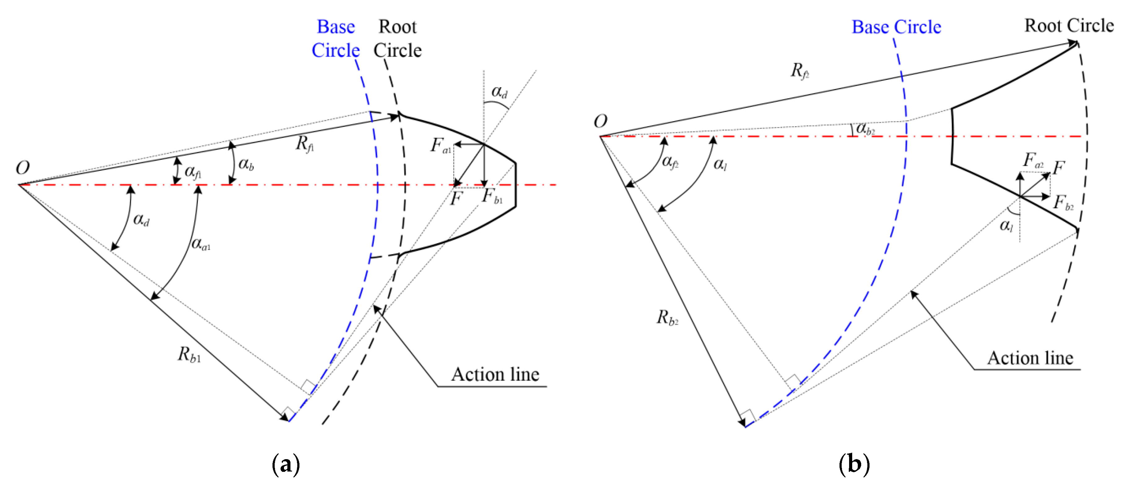
3. Load Distribution Calculation of the Harmonic Flexible Wheel

For a certain polar angle φ, a pair of HD teeth mesh with each other, as shown in Figure 6. After the transmission system is loaded, both the flexible wheel shell and the meshing tooth pair are elastically deformed. When the rigid wheel is fixed, an additional angle β for compensating the above two deformations is generated by the flexible wheel to ensure the meshing of the flexible wheel and the rigid wheel. Sufficiently large β values allow for the elimination of the clearance between adjacent pairs of teeth, thereby resulting in simultaneous contact between multiple pairs of gear teeth.
Based on the deformation coordinates, and considering the simultaneous engagement of multiple pairs of teeth comprising the harmonic gear, the mathematical models of two kinds of harmonic gears was established as follows:
For the conventional HD,
δ K + δ r + D K R K β = 0
For the disposable HD,
δ K + D K R K β = 0
δ K = i = 1 N λ K i F i
where δK represents the total elastic deformation of the contact teeth in the meshing area, and δr denotes the elastic deformation in the circumferential direction of the flexible wheel shell under load. Furthermore, DK denotes the backlash at contact point K of the tooth pair in the meshing area with no load, and RK represents the load radius of the tooth pair in the meshing area at contact point K. β, i, and N indicate the additional angles of the contact tooth pair in the meshing area required for compensating the deformation, serial number of the contact tooth in the meshing area, and number of contact teeth in the meshing area, respectively. In addition, λKi represents the total flexibility caused by the unit of the i-th contact tooth pair, and Fi is the load acting on the i-th contact tooth pair.
Considering that the flexible wheel deformation includes tooth contact deformation, bending deformation, ring gear deformation, and so on, a three-dimensional finite element model was used to calculate the flexibility matrix of HD in this study. On the deformed model, circumferential force was applied one by one along the tangent direction of the meshing point. The circumferential displacement of all meshing points was extracted to obtain the converted displacement, namely the flexibility matrix. According to the polar angle range corresponding to the no-load backlash in Figure 6, φ = −25°~50° was selected as the range of flexible wheel teeth that may mesh with the rigid wheel. The conversion displacement curves of the meshing points of the two kinds of HDs are as follows.
The tip in Figure 7 represents the circumferential displacement of the stressed tooth at the meshing point. As can be seen from Figure 7, due to the difference in structure, the tooth deformation of the conventional HD is smaller than that of the disposable HD when the load is applied. In addition, when the deformation of the loaded tooth is the largest and the farthest away from the loaded tooth, the smaller the displacement of the tooth is. When the different gear teeth of the flexible wheel are subjected to unit meshing force, the circumferential displacement produced by the meshing point represents the stiffness of the gear teeth. Then the corresponding flexibility can be solved.
The elastic deformation in the circumferential direction of the flexible wheel shell can be expressed as follows:
δ r = i = 1 N ξ i F i
where ξi is the circumferential deformation coefficient associated with the unit force on the i-th contact tooth pair. The load is decomposed into a radial force FQ and a tangential force FP. Based on Refs. [36,37], the force on the shell of the conventional flexible wheel is shown in Figure 8.
F Q = F sin α K 1 F P = F cos α K 1
The radial, circumferential, and axial displacement under load can be determined with
{ ω F = η r m 2 2 π B n = 2 , 4 , 6 ( l F l ) n ( x l ) n ( 2 n 3 ) ( 4 n 2 1 ) n ( n 1 ) f ( n ) ( F P sin n φ + n F Q cos n φ ) υ F = η r m 2 2 π B n = 2 , 4 , 6 ( l F l ) n ( x l ) n ( 2 n 3 ) ( 4 n 2 1 ) n 2 ( n 1 ) f ( n ) ( F P cos n φ n F Q sin n φ ) u F = 0
η = r m l
f ( n ) = α 5 n 5 α 4 n 4 α 3 n 3 + α 2 n 2 α 1 n α 0
α 5 = 1 2 η 2 ( 1 2 ν ) + η 4 , α 4 = 1 + η 2 ( η 2 2 ν ) , α 3 = 1 4 [ 9 + 2 η 2 ( 11 18 ν ) + η 4 ] , α 2 = 1 4 [ 7 2 η 2 ( 3 + ν ) + η 4 ] , α 1 = 1 4 [ 5 + 2 η 2 ( 7 10 ν ) ] , α 0 = 3 4 [ 1 2 η 2 ( 1 ν ) ] .
where l, lF, and B represent the total length of the flexible shell, the distance from the radial component of the load to the edge of the flexible shell, and the flexural strength of the flexible shell, respectively. Furthermore, E1 is the elastic modulus of the flexible wheel material, hδ denotes the thickness of the flexible shell, and ν1 is the Poisson’s ratio of the flexible wheel material.
The deformation of all contact points in the meshing area can be expressed in matrix form, as follows:
{ [ λ ] [ F ] + [ ξ ] [ F ] + [ D ] [ R K ] β = 0 ,             conventional       HD [ λ ] [ F ] + [ D ] [ R K ] β = 0 ,                                           disposable       HD
where [λ] is an n × n order flexibility matrix, [F] indicates an n × 1 load column vector, and [ζ] represents an n × n order coefficient matrix corresponding to the flexible wheel shell circumferential deformation. Moreover, [D] denotes an n × 1 backlash column vector with no load, and [RK] represents an n × 1 contact load radius column vector.
The harmonic gear is in balance when transmitting the torque. Moreover, the sum of the torque generated by the load at each contact point in the meshing area is the same as the total torque applied to the transmission system.
i = 1 N F i R K i cos α K i = T
Let H i = R K i cos α K i ; Equation (25) can be expressed as a matrix, as follows:
[ H ] T [ F ] = T
The load distribution model of the HD can be obtained by solving Equations (24) and (26). The specific solution process is as follows:
Step 1—Suppose that only a pair of gear teeth with the smallest no-load backlash is engaged, and the other gear teeth are not in contact. Record the number of meshing teeth n = 1, and the tooth pair number in the meshing area i = 1. Solve the initial load F1 and the compensation rotation angle β1.
Step 2—Gradually increase the number of meshing teeth, solve Equations (24) and (26), and obtain the corresponding compensation rotation angle β2……βn.
Step 3—When βn < 0 or βn > βn−1, stop the calculation. The last set of results that meet the constraints is the load distribution [F].
Since the no-load backlash D (see Figure 6) and flexibility [λ] (see Figure 7) of the disposable harmonic gear are significantly different from that of the conventional harmonic gear, the load distributions of the two HDs under full load 80N∙m are also different (see Figure 9). When the flexible wheel is loaded, contact occurs first at the position with the smallest backlash under the action of torsional deformation, and the contact force increases with the increase in the external load. Therefore, the maximum contact force of the HD occurs at the position with the smallest no-load backlash. It can be seen that at the maximum contact load, the disposable HD is lower than that of the conventional HD. In addition, there are certain differences between the meshing areas of the two HDs. After being loaded, the conventional flexible wheel is distorted due to the torsional deformation of the cylinder, which affects the backlash distribution. Therefore, the load distribution curve of the conventional flexible wheel under load is not completely symmetrical, which is consistent with the conclusion of [28]. The contact stress of the HD is discussed below.

4. Tooth Surface Contact Stress Calculation of the Harmonic Flexible Wheel

According to the Hertz contact theory, tooth contact in gear transmission can be considered equivalent to the contact between two cylinders, with the curvature of the radius values denoted as ρ1 and ρ2. The load contact area is expanded to an elliptical contact surface, and the maximum uniform load density on the contact surface is the tooth surface contact stress.
σ H max = F π L 1 / ρ v 1 ν 1 2 E 1 + 1 ν 2 2 E 2
where L represents the tooth width, ρν denotes the comprehensive curvature radius of the meshing point. ν1 and ν2 denote the Poisson’s ratios of the flexible and rigid wheels, respectively. Similarly, E1 and E2 represent the elastic modulus values of the flexible and rigid wheels, respectively.
The meshing of involute harmonic gears can be equivalent to the tangential interior of two cylinders (Figure 10). The overall curvature radius can be expressed as follows:
1 ρ i ν = 1 ρ i 1 1 ρ i 2
where ρi1 and ρi2 represent the curvature radii of the involute flexible and rigid wheel teeth at the meshing point, respectively.
The involute profile teeth are shown in Figure 11, and the comprehensive curvature radius in the meshing area of the disposable harmonic gear is shown in Figure 12.
The tooth surface contact stresses of the two kinds of HDs under full load are shown in Figure 13.
As can be seen from Figure 13, similar to the load distribution curve (see Figure 9), the maximum contact stresses of both the HDs appear in the position with the smallest no-load backlash. In addition, the maximum contact stress of the disposable HD under full load is lower than the yield strength of the flexible wheel material (960 MPa). Therefore, the disposable harmonic gear can realize short-term operations under full load.

5. Finite Element Analysis of the Disposable HD

The ABAQUS simulation software was used to establish a simplified contact model of the disposable harmonic gear. To simplify the calculation, the contact model was geared to consist of a flexible wheel, a rigid wheel, and a wave generator. The material properties of the three parts are shown in Table 2, and the simplified model of the disposable HD is shown in Figure 14. The “Dynamic, Explicit” analysis algorithms were used to establish the two steps of harmonic gear assembly and loading motion. In order for the contact tooth pairs in the meshing area to undergo the entire process from mesh-in to mesh-out, reference points were established at the centers of the two gears and the wave generator, and coupling constraints were established with the respective inner faces to realize rotational motion. Boundary conditions and loads were applied at the reference points. The wave generator was assumed to be completely rigid in the contact analysis. Two kinds of contacts were set in the finite element model—the contact between the inner surface of the flexible wheel and the outer surface of the wave generator, and the contact between the tooth surface of the flexible wheel and the rigid wheel. The inner surface and the tooth surface of the flexible wheel were defined as the contact surface, and the outer surface of the wave generator and the tooth surface of the rigid wheel were defined as the target surface.
In the assembly step, the flexible wheel was fixed, and the wave generator and the rigid wheel moved successively to the final position at a constant speed. In the loading step, the outer surface of the rigid wheel was fixed. The flexible wheel and the wave generator were applied with a uniform rotation boundary condition. Then the flexible wheel was applied with a torque of 80 Nm. The load increased linearly from zero to the maximum value after half of the step time and remained until the end of the step. The trajectory of the flexible wheel during the meshing process is shown in Figure 15. After inspection, there was no contour interference between the flexible wheel and the rigid wheel.
The finite element assembly model of the disposable harmonic drive and the partial enlargement of the meshing of the flexible wheel and the rigid wheel are shown in Figure 16. The contact between the flexible wheel and the rigid wheel during meshing is shown in Figure 17. Considering that nearly 30% of the gear teeth are in contact at the same time during transmission, a part of the meshing tooth pair was intercepted in this study. Finally, the normal contact forces (CNORMF) and tooth surface contact stresses (CPRESS) of the tooth pair after a complete meshing cycle was output (see Figure 18).
According to Figure 18, the contact force and stress are not uniformly distributed along the tooth width direction during harmonic gear transmission. Instead, the maximum value appears in the middle of the tooth surface, which is consistent with the conclusion of [22]. Figure 19 shows the comparison between the results of the theoretical calculation (see Figure 9 and Figure 13) and the finite element model simulation (see Figure 18).
As can be seen from Figure 19, the results of the theoretical calculation and the simulation analysis are close, and the maximum contact stress of the disposable HD is smaller than the yield strength of the flexible wheel.

6. Conclusions

The meshing and contact characteristics of the disposable HD were investigated by means of the Hertz contact theory and a finite element model. Furthermore, the differences in the no-load backlash, load distribution, and contact stress between two HDs were evaluated. The conclusions of this study are summarized as follows:
(1)
The minimum no-load backlash of the disposable HD occurs at the long axis center of the wave generator. In addition, the minimum and maximum no-load backlashes of the disposable HD in the meshing area are smaller than those of the conventional HD.
(2)
Due to different structures, the flexibility of the disposable HD is higher than that of the conventional HD. The load distribution and contact stress of the disposable HD are smaller in the meshing area.
(3)
The maximum contact stress of the disposable HD is smaller than the yield strength of the flexible wheel. The disposable harmonic gear can be used for short-time operations under full load.

Author Contributions

Conceptualization, G.W., Y.L. and X.P.; methodology, Y.Z.; software, Y.Z.; validation, Y.Z. and Y.L.; writing—original draft preparation, Y.Z.; writing—review and editing, Y.L. and X.P.; visualization, X.P. and G.W.; funding acquisition, Y.L. All authors have read and agreed to the published version of the manuscript.

Funding

This research was funded by the National Natural Science Foundation of China, grant number 51875117, and the Fundamental Research Funds for the Central Universities, grant number LH2020E035.

Institutional Review Board Statement

Not applicable.

Informed Consent Statement

Not applicable.

Data Availability Statement

The data presented in this study are available upon request from the corresponding author. The data are not publicly available due to copyright issues.

Conflicts of Interest

The authors declare no conflict of interest.

References

  1. Taghirad, H.D.; Be’langer, P.R. Modeling and Parameter Identification of Harmonic Drive Systems. J. Dyn. Syst.-T 1998, 120, 439–444. [Google Scholar] [CrossRef]
  2. Ma, D.; Rao, P.; Yan, S. Kinematics Analysis of Meshed Teeth Pairs of Harmonic Drive Gears Considering the Load Effect Using Computer Vision. In Proceedings of the Automation and Robotics of the 5th International Conference on Control, Beijing, China, 19–22 April 2019; pp. 212–217. [Google Scholar]
  3. Vivet, M.; Mundo, D.; Tamarozzi, T.; Desmet, W. An analytical model for accurate and numerically efficient tooth contact analysis under load, applied to face-milled spiral bevel gears. Mech. Mach. Theory 2018, 130, 137–156. [Google Scholar] [CrossRef]
  4. Thomas, B.; Sankaranarayanasamy, K.; Ramachandra, S. Search method applied for gear tooth bending stress prediction in normal contact ratio asymmetric spur gears. Proc. Inst. Mech. Eng. Part C J. Mech. Eng. Sci. 2018, 232, 203–210. [Google Scholar] [CrossRef]
  5. Mohammed, J.K.; Khdir, Y.K.; Kasab, S.Y. Contact stress analysis of spur gear under the different rotational speed by theoretical and finite element method. Acad. J. Nawroz Univ. 2018, 7, 213–222. [Google Scholar] [CrossRef]
  6. Wen, Q.; Du, Q.; Zhai, X. An analytical method for calculating the tooth surface contact stress of spur gears with tip relief. Int. J. Mech. Sci. 2019, 151, 170–180. [Google Scholar] [CrossRef]
  7. Sato, T.; Umezawa, K.; Ishikawa, J. Effects of contact ratio and profile correction of spur gears on the rotational vibration. Trans. JSME Sec. C 1983, 49, 448–455. [Google Scholar] [CrossRef]
  8. Liou, C.H.; Lin, H.H.; Oswald, F.B. Effect of contact ratio on spur gear dynamic load with no tooth profile modifications. J. Mech. Des. 1996, 118, 439–443. [Google Scholar] [CrossRef]
  9. Lin, H.H.; Lee, C.W.; Oswaid, F.B.; Townsend, D.P. Townsend, Computer-aided design of high-contact-ratio gears for minimum dynamic load and stress. J. Mech. Des. 1993, 115, 171–178. [Google Scholar] [CrossRef]
  10. Kahraman, A.; Blankenship, G.W. Gear dynamics experiments, part-2: Effect of involute contact ratio. Power Transm. Gearing Conf. 1996, 88, 381–396. [Google Scholar]
  11. Li, S.T. Gear contact model and loaded tooth contact analysis of a three-dimensional, thin-rimmed gear. J. Mech. Des. 2002, 124, 511–517. [Google Scholar] [CrossRef]
  12. Li, S.T. Deformation and Bending Stress Analysis of a Three-dimensional, Thin-rimmed Gear. J. Mech. Des. 2002, 124, 129–135. [Google Scholar] [CrossRef]
  13. Ravivarman, R.; Palaniradja, K.; Sekar, R.P. Evolution of balanced root stress and tribological properties in high contact ratio spur gear drive. Mech. Mach. Theory 2018, 126, 491–513. [Google Scholar] [CrossRef]
  14. Wang, Y.; Ren, S.; Li, Y. Design and manufacturing of a novel high contact ratio internal gear with a circular arc contact path. Int. J. Mech. Sci. 2019, 153, 143–153. [Google Scholar] [CrossRef]
  15. Huang, K.; Yi, Y.; Xiong, Y. Nonlinear dynamics analysis of high contact ratio gears system with multiple clearances. J. Braz. Soc. Mech. Sci. Eng. 2020, 42, 98. [Google Scholar] [CrossRef]
  16. Jia, C.; Fang, Z. Design and analysis of double-crowned high-contact-ratio cylindrical gears considering the load sharing of the multi-pair contact. Mech. Mach. Theory 2019, 131, 92–114. [Google Scholar] [CrossRef]
  17. Sun, X.; Han, L.; Wang, J. Tooth modification and loaded tooth contact analysis of China Bearing Reducer. Proc. Inst. Mech. Eng. Part C J. Mech. Eng. Sci. 2019, 233, 6240–6261. [Google Scholar] [CrossRef]
  18. Rama, T.; Clement, C.D. Study on the quality and tooth root load carrying capacity of the high contact ratio asymmetrical gear tooth machined using WCEDM process. Mater. Manuf. Process. 2020, 35, 1352–1361. [Google Scholar]
  19. Yifan, H.F.; Zhao, Z.F.; Ma, H. Effects of tooth modification on the dynamic characteristics of thin-rimmed gears under surface wear. Mech. Mach. Theory 2020, 150, 103870. [Google Scholar]
  20. Donghui, M.; Jianing, W.; Liu, T. Deformation analysis of the flexspline of harmonic drive gears considering the driving speed effect using laser sensors. Sci. China Technol. Sci. 2017, 60, 1175–1187. [Google Scholar]
  21. Dong, H.M. Elastic deformation characteristic of the flexible wheel in harmonic drive. In ASME/IFToMM International Conference on Reconfigurable Mechanisms and Robots (ReMAR); IEEE: London, UK, 2009; pp. 363–369. [Google Scholar]
  22. Dong, H.M.; Zhu, Z.D.; Zhou, W.D. Dynamic Simulation of Harmonic Gear Drives Considering Tooth Profiles Parameters Optimization. J. Comput. 2012, 7, 1429–1436. [Google Scholar] [CrossRef] [Green Version]
  23. Chen, X.X.; Lin, S.Z.; Xing, J.Z. Deformation of flexible wheel under transmission force in harmonic drive. Adv. Mat. Res. 2010, 97–101, 3536–3539. [Google Scholar]
  24. Chen, X.X.; Liu, Y.S.; Xing, J.Z. A novel method based on mechanical analysis for the stretch of the neutral line of the flexible wheel cup of a harmonic drive. Mech. Mach. Theory 2014, 76, 189–196. [Google Scholar] [CrossRef]
  25. Chen, X.X.; Liu, Y.S.; Xing, J.Z. Neutral line of flexible wheel in harmonic driver. J. Mech. Eng. 2014, 50, 1–19. [Google Scholar] [CrossRef]
  26. Kayabasi, O.; Erzincanli, F. Shape optimization of tooth profile of a flexible wheel for a HD by finite element modeling. Mater. Des. 2007, 28, 441–447. [Google Scholar] [CrossRef]
  27. Chen, X.; Liu, Y.; Xing, J. The parametric design of double-circular-arc tooth profile and its influence on the functional backlash of HD. Mech. Mach. Theory 2014, 73, 1–24. [Google Scholar] [CrossRef]
  28. Le, K.X.; Quan, Y.X.; Zhou, G.R. Theoretical calculation of space dynamic meshing loads in harmonic gear drive. J. Zhejiang Univ. 1995, 2, 219–229. [Google Scholar]
  29. Zou, C.; Tao, T.; Jiang, G. Deformation and stress analysis of short flexible wheel in the HD system with load. In Proceedings of the 2013 IEEE International Conference on Mechatronics and Automation, Takamatsu, Japan, 4–7 August 2013; pp. 676–680. [Google Scholar]
  30. Sahoo, V.; Maiti, R. Evidence of secondary tooth contact in HD, with involute toothed gear pair, through experimental and finite element analyses of stresses in flex-gear cup. Proc. Inst. Mech. Eng. Part C J. Mech. Eng. Sci. 2018, 232, 341–357. [Google Scholar] [CrossRef]
  31. Routh, B.; Maiti, R.; Ray, A.K. An investigation on secondary force contacts of tooth pairs in conventional HDs with involute toothed gear set. Proc. Inst. Mech. Eng. Part C J. Mech. Eng. Sci. 2016, 230, 622–638. [Google Scholar] [CrossRef]
  32. Yang, C.; Hu, Q.; Liu, Z. Analysis of the Partial Axial Load of a Very Thin-Walled Spur-Gear (Flexible wheel) of a HD. Int. J. Precis. Eng. Man. 2020, 30, 1–13. [Google Scholar]
  33. Sahoo, V.; Maiti, R. Load sharing by tooth pairs in involute toothed HD with conventional wave generator cam. Meccanica 2018, 53, 373–394. [Google Scholar] [CrossRef]
  34. Sahoo, V.; Mahanto, B.S.; Maiti, R. Stresses in flex gear of a novel HD with and without pay load. Aust. J. Mech. Eng. 2020, 1, 1–15. [Google Scholar] [CrossRef]
  35. Xie, J.R. The meshing analysis method of the harmonic gear drive with the elliptical cam wave generator. Opt. Precis. Eng. 1980, 3, 33–40. [Google Scholar]
  36. Kokhanovskii, G.I.; Polenov, V.S.; Spiridonov, V.V. Calculating the stress and strain state of the flexible wheel of a wave toothed transmission. Sov. Appl. Mech. 1973, 9, 1355–1358. [Google Scholar] [CrossRef]
  37. Polenov, V.S. Investigation of the stress-strain state of flexible elements in wave drives. Sov. Appl. Mech. 1981, 17, 34–39. [Google Scholar] [CrossRef]
Figure 1. Structure of two kinds of flexible wheels: (a) the conventional flexible wheel; (b) the disposable flexible wheel.
Machines 10 00096 g001
Figure 2. Deformation of the conventional flexible wheel with no load after assembly.
Machines 10 00096 g002
Figure 3. Deformation of the disposable flexible wheel with no load after assembly.
Machines 10 00096 g003
Figure 4. (a) The deformation of the conventional flexible wheel rim; (b) the deformation of the disposable flexible wheel rim.
Machines 10 00096 g004
Figure 5. Engagement diagram of harmonic contact tooth pair. Two cases of flexible wheel teeth under assembly and load are included.
Machines 10 00096 g005
Figure 6. Backlash under no load of two kinds of HDs.
Machines 10 00096 g006
Figure 7. (a) The conversion displacement of the conventional flexible wheel; (b) the conversion displacement of the disposable flexible wheel.
Machines 10 00096 g007
Figure 8. Force on the conventional flexible wheel shell [36,37].
Machines 10 00096 g008
Figure 9. Harmonic transmission load distribution of the two HDs.
Machines 10 00096 g009
Figure 10. The Hertz contact model of involute harmonic gears.
Machines 10 00096 g010
Figure 11. (a) The involute flexible gear tooth; (b) the involute rigid gear tooth.
Machines 10 00096 g011
Figure 12. (a) Curvature radii of the flexible and rigid wheel; (b) comprehensive curvature radius.
Machines 10 00096 g012
Figure 13. Harmonic transmission contact stress of involute tooth profile.
Machines 10 00096 g013
Figure 14. Simplified model of the disposable harmonic drive.
Machines 10 00096 g014
Figure 15. The trajectory of the flexible wheel.
Machines 10 00096 g015
Figure 16. Finite element assembly model and the partial enlargement of the meshing area of the disposable HD.
Machines 10 00096 g016
Figure 17. Meshing contact diagram of partial tooth pairs during transmission.
Machines 10 00096 g017
Figure 18. (a) The normal contact force of the disposable flexible wheel under full load; (b) the contact stresses of the disposable flexible wheel under full load.
Machines 10 00096 g018
Figure 19. Results comparison of the involute disposable HD: (a) load distribution; (b) contact stress.
Machines 10 00096 g019
Table 1. Parameters of the HD.
The Conventional HDThe Disposable HD
ParameterFlexible WheelRigid WheelFlexible WheelRigid Wheel
Number of teeth Z200202200202
Module m (mm)0.160.160.160.16
Teeth width L (mm)10101010
Modification coefficient2.32.02.72.85
Total length l (mm)3510
Pressure angle α0 (°)20 20
Transmission ratio100100
Table 2. Parameters of the flexible wheel, rigid wheel, and wave generator.
Flexible WheelRigid Wheel and Wave Generator
Material40CrNiMoA45Steel
Density ρ (kg/m3)78507870
Young’s modulus E (MPa)211,000209,000
Poisson’s ratio ν0.30.27
Publisher’s Note: MDPI stays neutral with regard to jurisdictional claims in published maps and institutional affiliations.

