Article

Numerical and Experimental Analysis for the Dynamics of Flawed–Machining Rod–Disk Rotor with Inner Misalignment

1
Wuhan Institute of Marine Electric Propulsion, Wuhan 430000, China
2
School of Mechanical Engineering, Xi’an Jiaotong University, Xi’an 710049, China
*
Author to whom correspondence should be addressed.
Machines 2022, 10(5), 355; https://doi.org/10.3390/machines10050355
Submission received: 5 April 2022 / Revised: 28 April 2022 / Accepted: 3 May 2022 / Published: 9 May 2022
(This article belongs to the Section Machine Design and Theory)

Abstract

:
The nonlinear dynamic effects of the misalignment between inner disks in a flawed–machining rod–disk rotor is studied. Non–uniform stress distribution due to inner misalignment is obtained based on 3D static solution. The concomitant unbalances, including constant mass eccentricity and speed–variant rotor bending, are taken into account in the nonlinear dynamics. The dynamic results show that rotor bending leads to stability reduction and vibration growth. There is a distinctive feature in that the rotor’s vibration goes up again after critical speed. The maximum allowable inner misalignment is obtained according to its stability boundaries. An uneven tightening method is also presented to reduce adverse effects when the inner misalignment exists. Moreover, an experiment is designed to measure the vibration characteristics for the rod–disk rotor bearing system with inner misalignment. The results show that the theoretical result of vibration amplitude of the flawed rod–rotor bearing system is basically consistent with the experimental value. It is also found that the precise rotor performs the periodic motion, but the flawed rod–disk rotor exhibits the period–doubling orbit. This phenomenon proves that the flawed rod–disk rotor loses stability more easily than the precise rotor due to inner misalignment. However, the amplitude of harmonic frequency components for the precise rod–disk rotor system is obviously larger than the flawed rod–disk rotor system with inner misalignment. The peak value of the vibration amplitude increases when the inner misalignment becomes larger. On the whole, this work presents numerical and experimental analysis to study the dynamics of flawed-machining rod–disk rotor with inner misalignment. It also establishes the relationship between centration precision and dynamic features.

1. Introduction

The rod–disk rotor has a special structure in which all rotational disks are combined by several rods. This kind of rotor has been used in some gas turbines and aeroplane engines. Due to flawed machining, there is usually centration error after rotor assembly which can cause inner misalignment between different rotational disks.
Misalignment is one of the most common faults in rotor systems. The current studies mainly consider the shaft–to–shaft misalignment as the common sources of vibrations. When two or more shafts are rigidly coupled together and supported by three or more bearings, the bearing reaction forces are sensitive to lateral misalignment [1,2,3]. Kumar et al. [4] proposed a novel trial misalignment approach to estimate the misalignment with a similar concept as the trial unbalance in the rotor balancing. Active magnetic bearing misalignment with the rotor has been investigated with residual misalignment and additional trial misalignment cases. Lu et al. [5] applied the proper orthogonal decomposition method to the dimension reduction of a dual rotor–bearing experiment rig which is similar to an aero–engine rotor. Liu et al. [6] built a rotor system with a misalignment fault experiment table and verified the effectiveness of this new index for detecting the slight misalignment fault of the rotor system. Abdou et al. [7] studied the dynamic response of fluid film bearing of finite length which is subjected to rotor misalignment. Srinivas et al. [8] presented the modelling, analysis, and identification of various system faults in the presence of angular misalignment in coupled rotor–train systems integrated with an auxiliary AMB support. Sawalhi et al. [9] shed light on vibration modelling and diagnosis of misalignment beyond traditional approaches. Li et al. [10] investigated the nonlinear dynamic behaviours of an unsymmetrical generator rotor system supported on the journal bearings. Fu et al. [11] investigated the propagation of bounded uncertainties in the dynamic response of a misaligned rotor using a Legendre collocation based non–intrusive analysis method. Pennacchi et al. [12] aimed to model angular and parallel misalignment and ascertain pertinent diagnostic information. The proposed method is suitable for every type of shaft–line supported by journal bearings. Verma et al. [13] inspected the different types of misalignments using diagnostic media such as stator current signature as well as rotor vibration signal, and found that current signature alone can predict the misalignment effect without the use of vibration signal. Tapia et al. [14] established the criteria for implementing a system for detecting and locating faults using state observers based on the mathematical model of a rotor bearing mass system. Mogal et al. [15] proposed an order analysis technique of vibration analysis for unbalance and misalignment fault diagnosis. The fault type and location are identified from phase and amplitude. Ma et al. [16] systematically investigated oil–film instability laws of an overhung rotor system with parallel and angular misalignments in the run–up and run–down processes, aiming at the oil–film instability of the sliding bearings at high speeds.
It is obvious that the misalignment appears between two or more rotors in the present works. However, there is probably misalignment between different inner parts, such as rotational disks in a rod–disk rotor. When these disks do not have the same axis, there is definitely inner misalignment in this combined rotor.
In this paper, the inner misalignment between rotational disks in one rod–disk rotor is considered and investigated using a static–dynamic coupling calculating process. The nonlinear behaviours of the rod–disk rotor bearing system have been obtained by combining the 3D finite element method and rotor–dynamics analysis. The particular features of the flawed rod–disk rotor, such as stability, vibration, and dynamic balance, are studied, and some designing suggestions are proposed based on the analysis results. Moreover, the theoretical data of vibration amplitude of the flawed rod–disk rotor system are basically consistent with the experimental value.

2. Static Features of Flawed Rod–Disk Rotor with Inner Misalignment

Referring to the compressor structure of a gas turbine rotor, a similar rod–disk rotor is shown in Figure 1. Three contiguous disks are connected by several radial–distributed rods in this combined rotor. Each rod has identical elongation. Two axial assembly surfaces between the disks (red lines) are designed to be connected, and all rods are mounted to be against disk–holes (blue lines). The above assembly steps can ensure that the rotor has sufficient centration precision. This rod–disk rotor is supported by two cylindrical sliding bearings. The working speed for the rotor bearing system is 7500 r/m, and the other parameters are listed in Table 1.

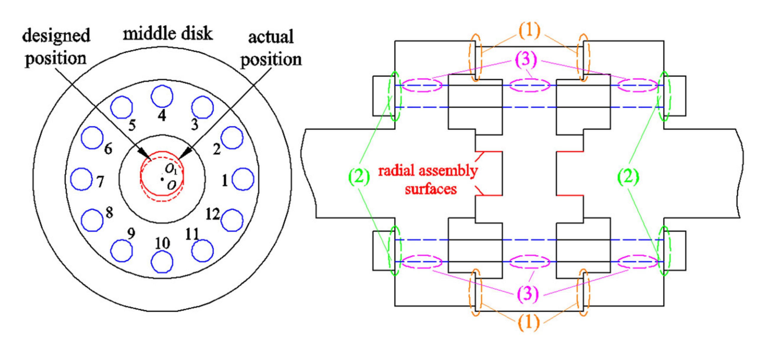
2.1. Inner Misalignment and Static Solution

The inner misalignment is described in Figure 2. The middle disk includes two symmetrical grooves. It is assumed that radial assembly surfaces deviate from designed centre O to actual centre O1 because flawed machining exists. Meanwhile, two other disks are also precisely machined. As a result, the inner misalignment appears in the rod–disk rotor because there is a centration error between middle disk and two other disks. The deviation distance h between O and O1 is defined as the misalignment value. Moreover, three other sorts of interfaces exist in this rotor: (1) interfaces (orange) between disks; (2) interfaces (green) between rod–heads and disks; and (3) interfaces (pink) between holes and rods.
When misalignment value equals 10μm, the 3D flawed rod–disk rotor can be meshed by 26,592 8–node elements. In order to make it recognizable, the inner misalignment value has been magnified 800 times in Figure 3.
For a pair of contact surfaces in 3D static model, the total potential energy E can be calculated according to reference [17].
b = b n , b t W = 1 2 b T Δ b b T η E = 1 2 u T K R u u T Q + W
When ∂E/∂u = 0, the static analysis method can be carried out by solving the following equations for the flawed rod–disk rotor.
K R + K Λ B T B 0 u η = Q Q Λ b 0 b = b 0 + b u u = b 0 + B u K Λ = B T Δ B Q Λ = B T Δ b 0  
As the contact state varied slowly, the above iteration is applied to calculate contact equations and the static stress can be obtained.

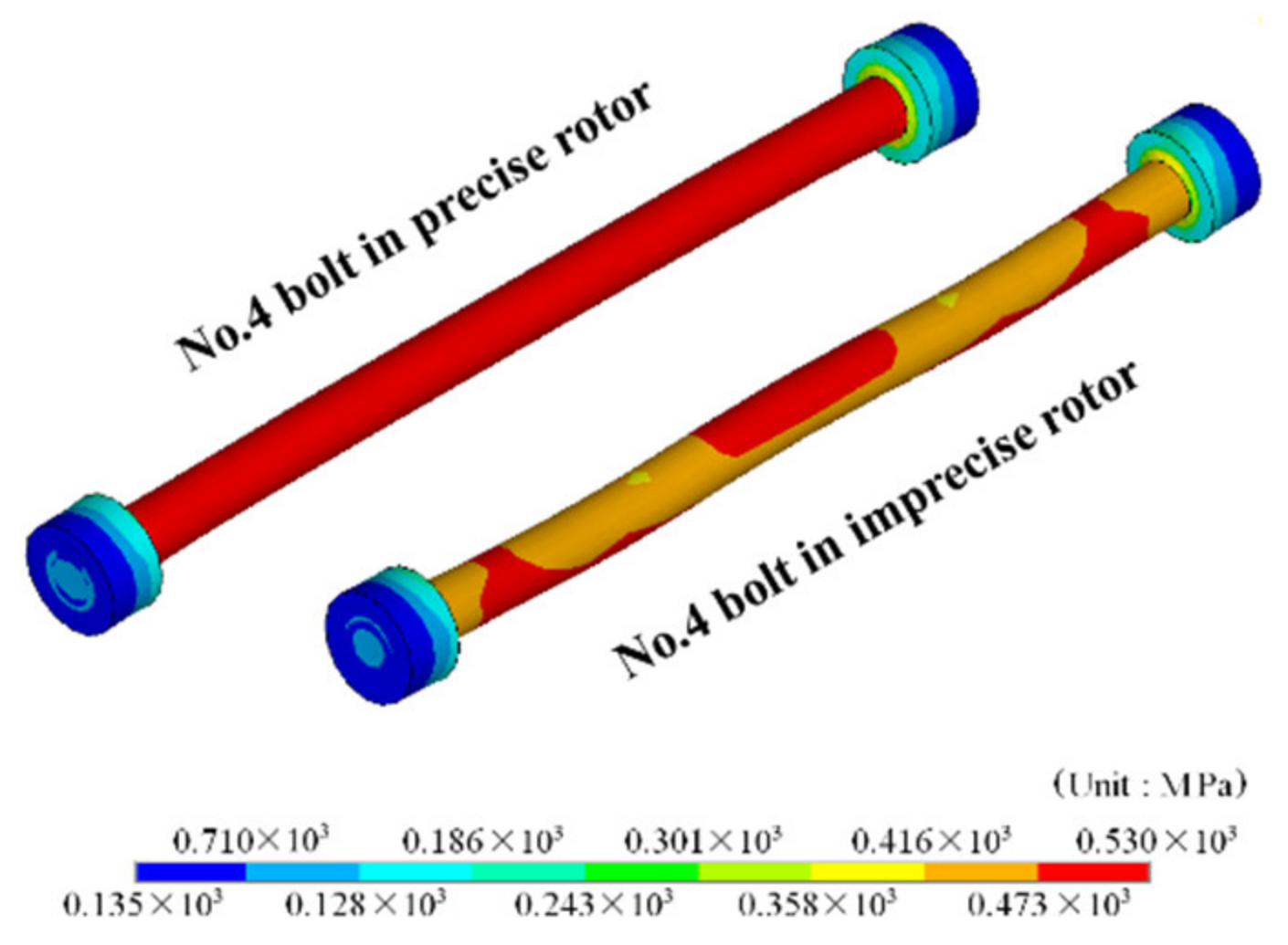
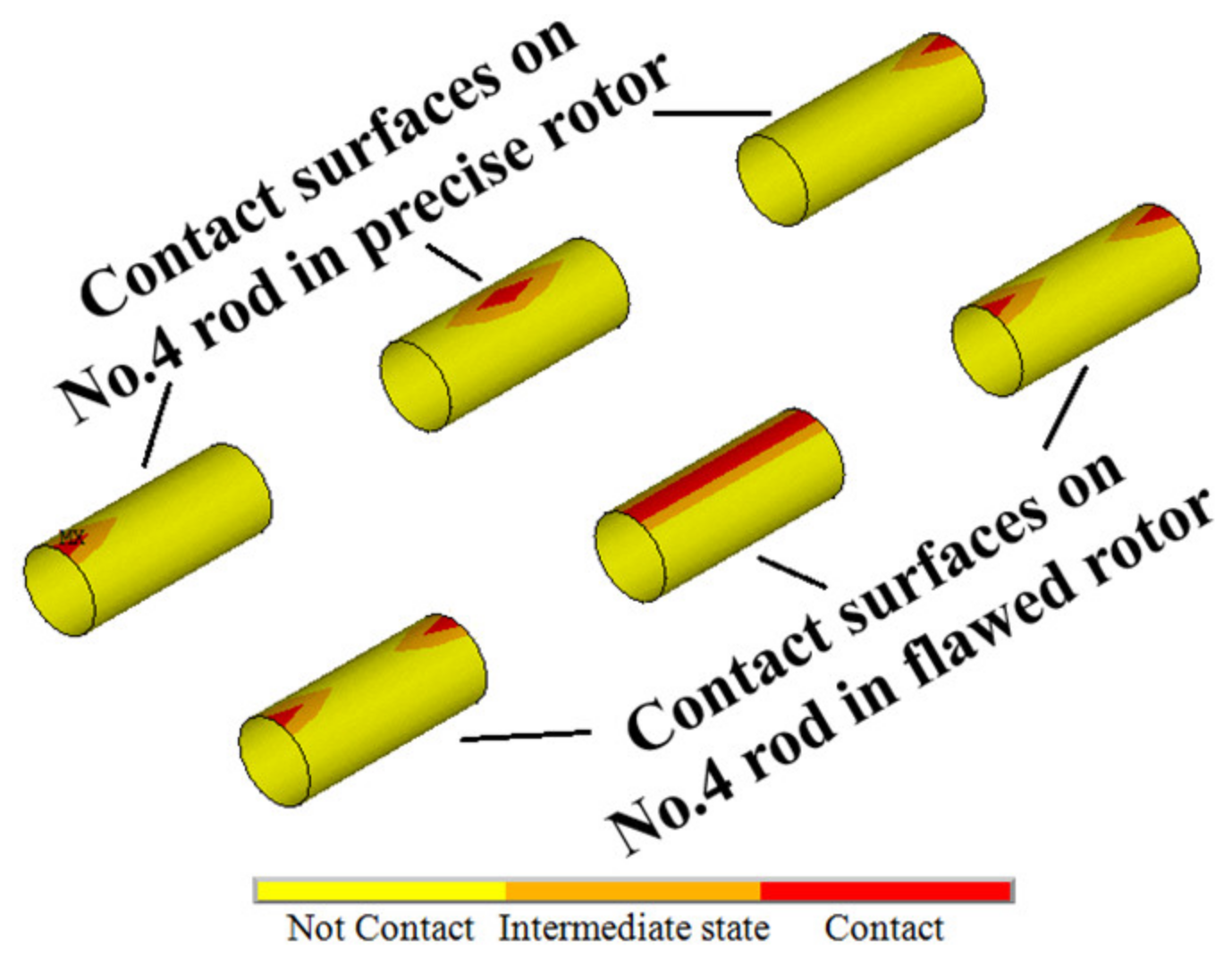
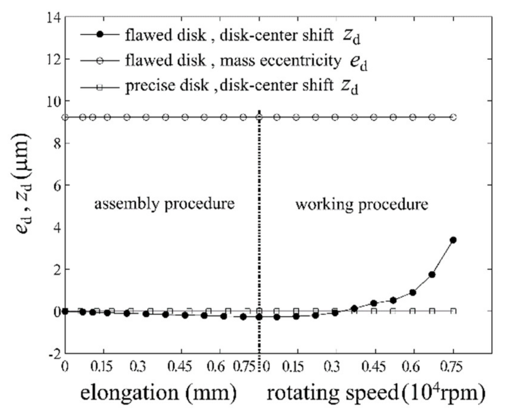
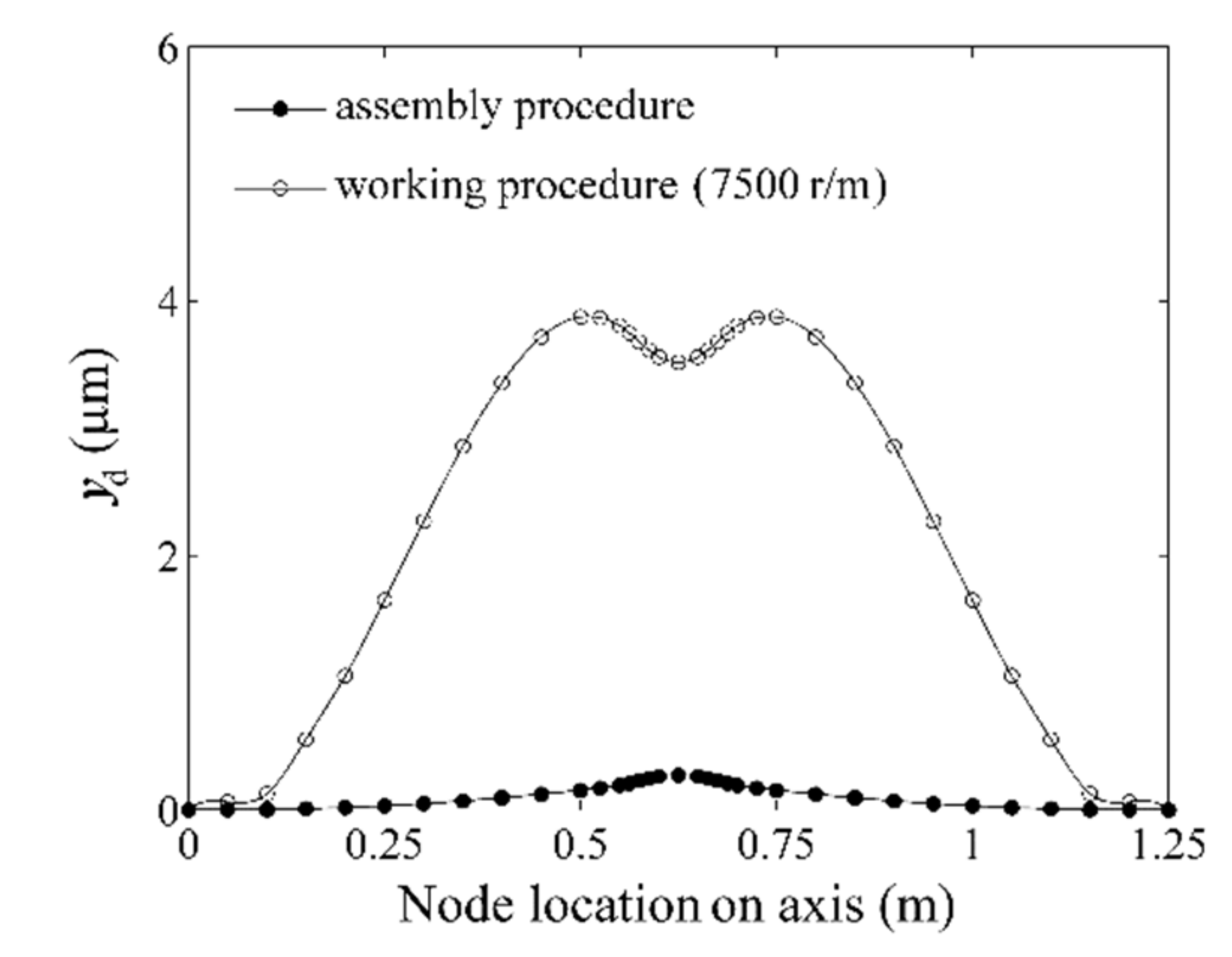
2.2. Static Analysis of the Flawed Rod–Disk Rotor

The static results of precise rotor are introduced to be a comparative reference. Figure 4 shows that uneven stress and rotor bending appear on the rod of flawed rotor; meanwhile, the corresponding rod in precise rotor has uniform stress distribution at its tensile region. This is because radial disk–holes have downward displacements and their surfaces press rods when the radial assembly surfaces have deviation.
Figure 5 demonstrates that the contact area on the flawed rotor’s rod is obviously larger because some rods in flawed rotors are completely pressed by the middle disk as it has vertical displacement due to inner misalignment.
Rod deformation triggers disk–centre shift (zd) for flawed disks (Figure 6). In the assembly procedure, zd equals 0.27 μm and inner misalignment causes a mass eccentricity (ed = 9.22 μm). When rotating speed goes up, ed keeps constant but zd increases gradually up to 3.39 μm. Meanwhile, the precise disk hardly has disk–centre shift. Therefore, the accuracy is sufficient to calculate the static stress and contact state for the flawed rod–disk rotor with inner misalignment.
Every node of the shaft and disks has a disk–centre shift zd. As a result, the rod–disk rotor has an overall bending yd = (z1,…, zd,…, zk) which is shown in Figure 7. Initial bending is formed in the assemble process. Moreover, the bending value becomes larger during the working period under the influence of centrifugal force.

3. Nonlinear Equations and Solving Algorithm

For the flawed rod–disk rotor with inner misalignment, the dynamic equations should consider an additional rotor bending on the base of traditional factors. Furthermore, the dynamic equations are divided into linear and nonlinear components for the sake of reducing degrees of freedom and adding forces on the nonlinear DOFs.
M m m R M n m R       M m n R M n n R u ¨ m u ¨ n + G m m R G n m R       G m n R G n n R u ˙ m u ˙ n + K m m R K n m R       K m n R K n n R u m u n y d m y d n = m e d ω 2 0 + g m g n + f b 0
in which nonlinear sections have m DOFs and linear sections have n DOFs.
Then, the residual flawed rotor bearing system can be written as Equation (4)[18] after carrying out the DOFs reduction process based on transformation matrix P. After reducing the equations, the total DOFs of residual flawed rotor bearing system number 27, composed of 15 nonlinear DOFs (from three disk nodes and two bearing nodes) and 12 linear eigenmodes.
M p q ¨ + G p q ˙ + K p q = Q   p
with M p = P T M R P ,       K p = P T K R P ,       G p = P T G R P q = P u ,       Q p = P T K R y d + g + m e d ω 2 + f b       .
When unbalance force medω2 and rotor bending yd change under the rotating period T, the solutions of dynamic equations can be calculated based on the variable X which contains displacement and speed simultaneously
d X d t = d d t q q ˙ = q ˙ M p 1 Q p K p q G p q ˙ X t = X t + T
Nonlinear description is applied to define the periodic solutions X(t) at the whirling state whose excitation parameter λ equals to medω2 and yd.
H λ 0 , X = X t + T X t = 0
Therefore, Newton’s iterative method can be used to approach X(t) when λ = λ0 based on Taylor’s expansion.
X t = X 0 + H X 0 1 H λ 0 , X H λ 0 , X 0
In different working conditions, the n + 1 iterative substep is calculated based on n substep solution Xn.
X n + 1 = X n H λ , X X n 1 H λ , X λ Δ λ λ n + 1 = λ n + Δ λ

4. Dynamic Features of Flawed Rod–Disk Rotor System

A common integral rotor only has mass eccentricity in the manufacturing process but it does not have bending deformation due to assembly error. There will definitely be different dynamic features for the integral and rod–disk rotor bearing system. In this part, two kinds of rotor with identical size are analysed to find out the essential discrepancy.

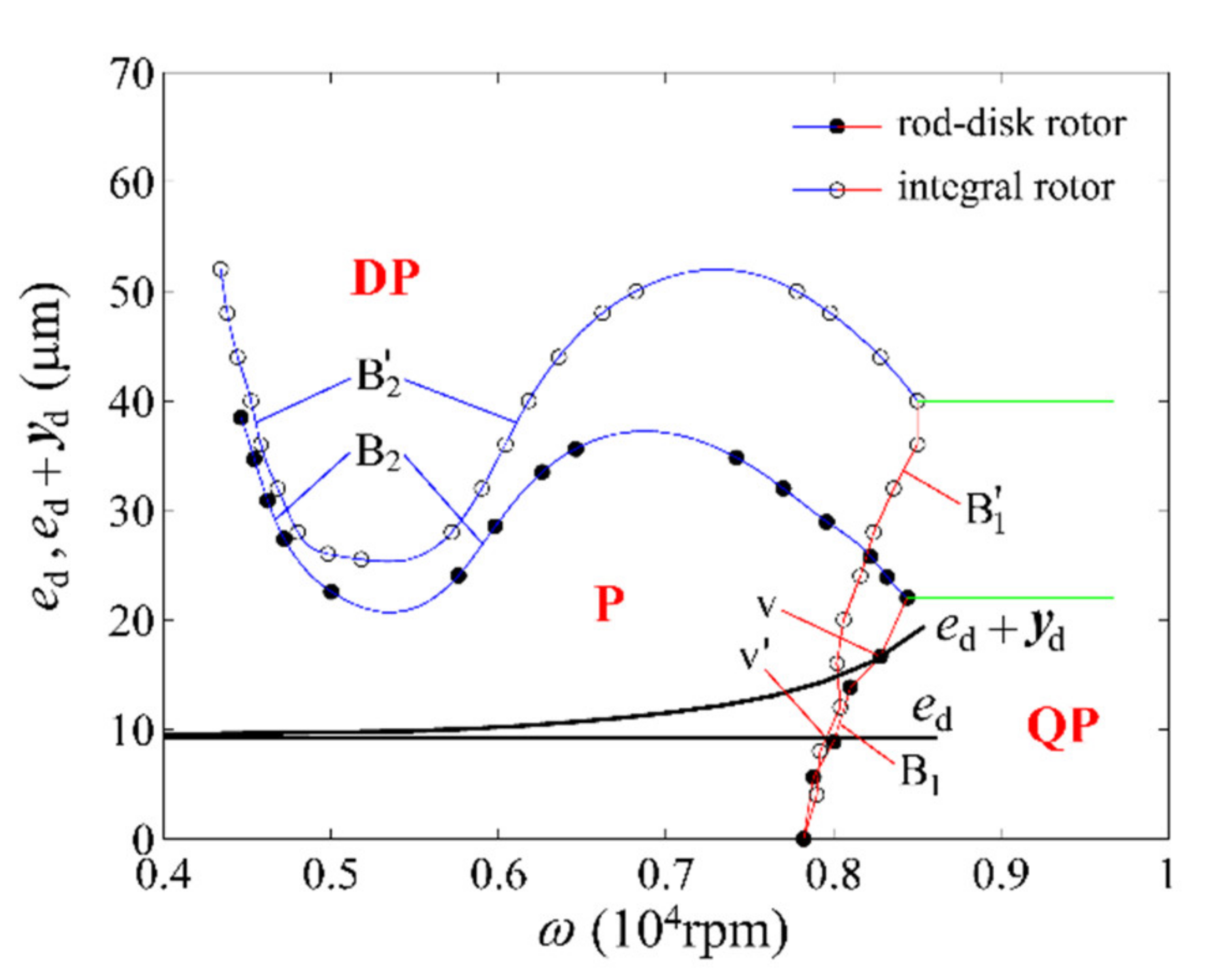
4.1. Global Stability Features

Figure 8 shows the global stability features of both rotor bearing system. Periodic, quasi–periodic, and period–doubling solutions are defined as P, QP, and DP areas, respectively. B1–B2 (B’1–B’2) lines represent the boundaries of quasi–periodic and period–doubling solutions for both rod–disk and integral rotor systems. The curves of (ed + yd) and ed, which come from the results of disk–centre shift, pass through the lines of B1 and B’1 at the crossing points v and v’. It is found that the flawed rod–disk (integral) rotor performs periodic motions when ω < ω v (ω v’) and exhibits quasi–periodic motions when ωω v (ω v’).
It can be seen that the area of stable solutions (P area) is much smaller than that of the integral rotor. It is proven that the stability of rod–disk rotor system decreases significantly due to inner misalignment between disks.

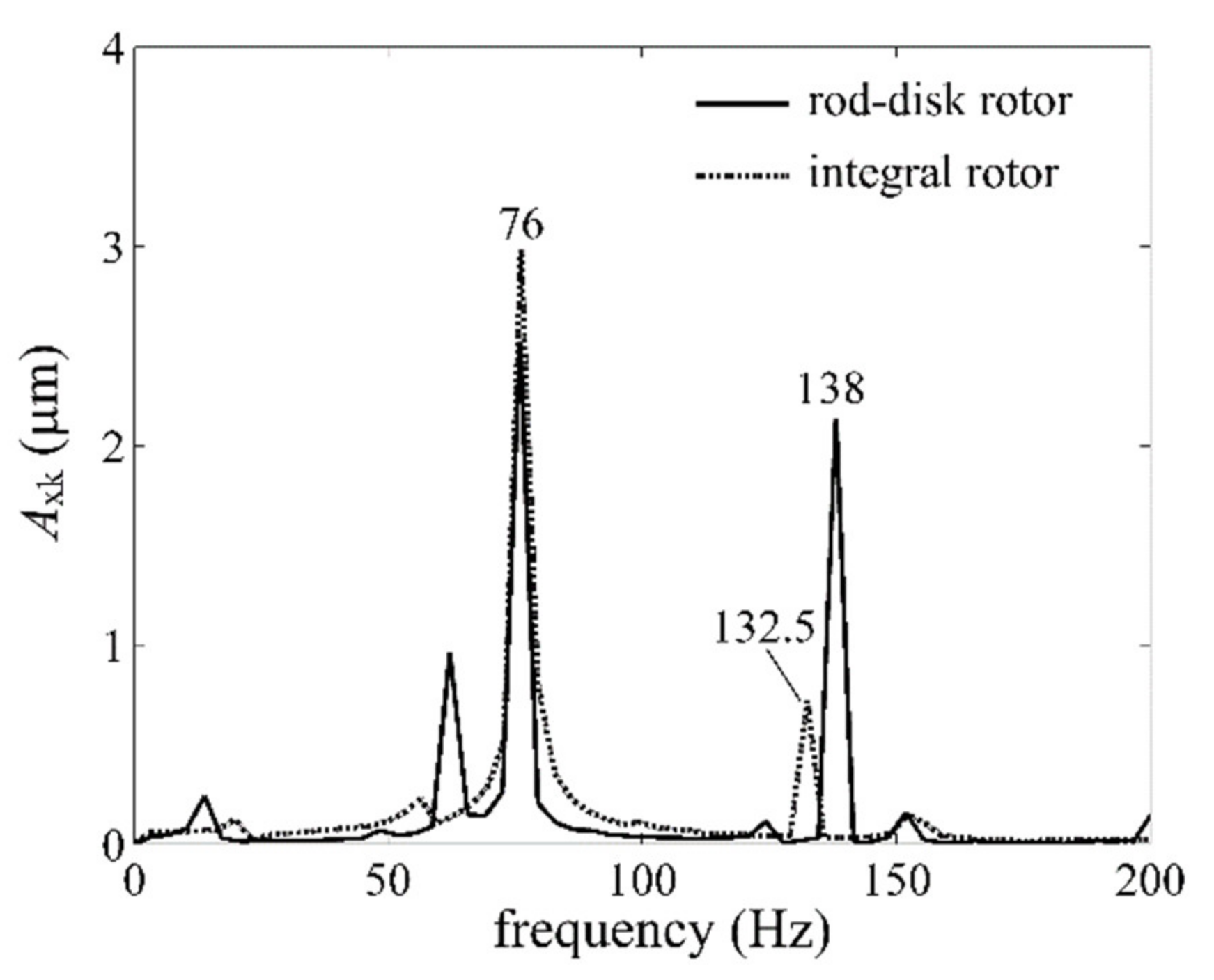
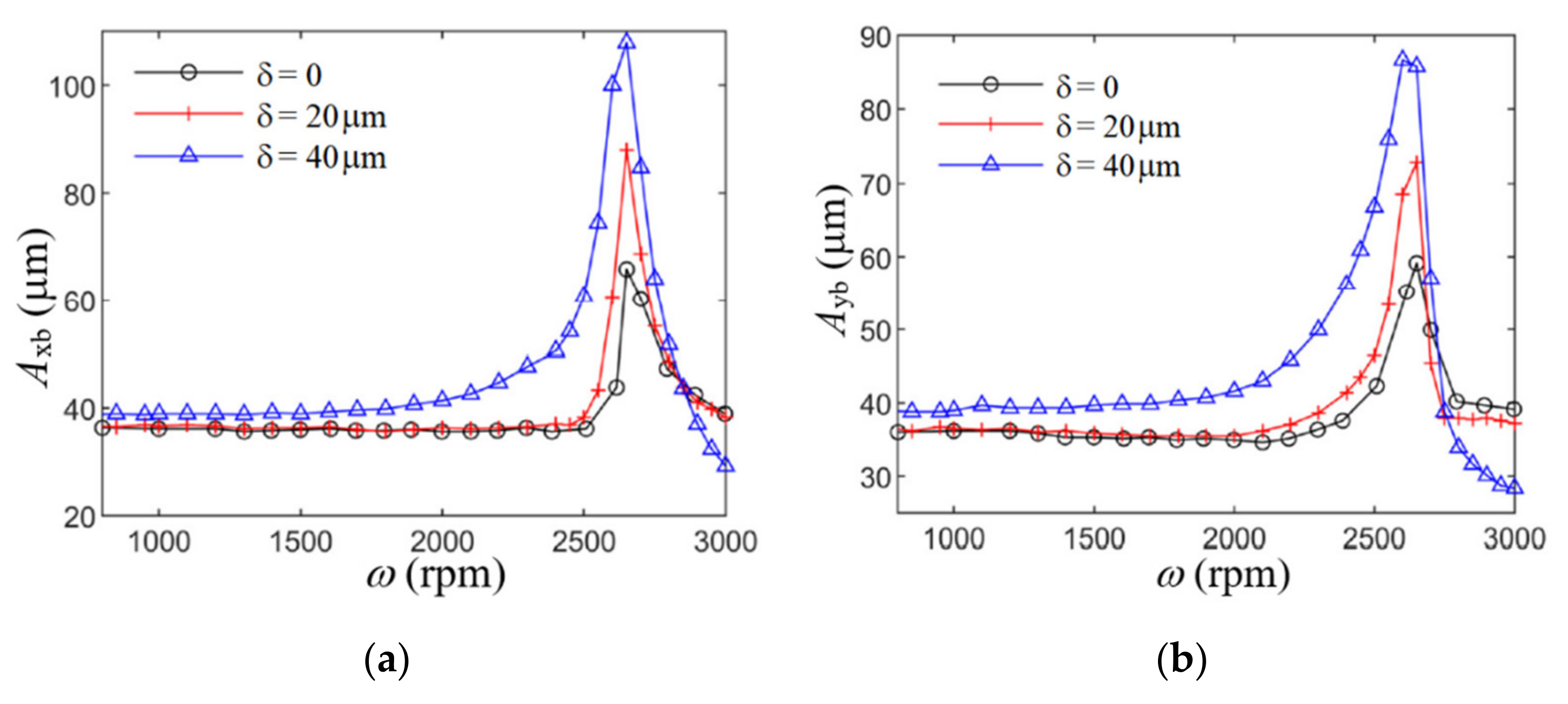
4.2. Nonlinear Vibration

The characteristics of nonlinear vibration for both rod–disk rotor and integral rotor are shown in Figure 9a. It is shown that two kinds of rotors have almost identical critical speed ωc which equals roughly 4800 r/m. However, the vibration amplitude of the integral rotor is obviously smaller than that of flawed rod–disk rotor. This indicates that the speed–variant rotor bending has little influence on the critical speed, but it can lead to larger vibration amplitude due to larger unbalance pulls.
Moreover, a special feature can be seen that the amplitude of flawed rod–disk rotor increases again after the critical speed ωc no matter whether the dynamic balance is carried out. This phenomenon is also found for a gas turbine (a typical rod–disk rotor) in the dynamic balancing process, whose experimental measuring data are shown in Figure 9b without heat and gas. In the same way, the vibration of the gas turbine increases again regardless of whether dynamic balance happens after the critical speed 2200 r/m, and the vibration amplitude becomes much smaller than at other velocities after the balance speed.
As to the reason the vibration of the flawed rod–disk rotor will rise after dynamic balance, the balance vector fc can be written as the following formula in order to reduce its unbalance component as much as possible at the critical speed ωc.
f c = m e ω c 2 + K R y d F c = f c + m e ω c 2 + K R y d = 0
Obviously, the vibration amplitude theoretically equals zero after adding balance vector fc when ω = ωc. However, the unbalance excitation vector F is much larger than Fc when ω > ωc. As the result, the vibration amplitude rises again after critical speed.
F = f c + m e ω 2 + K R y d = m e ω 2 ω c 2
Therefore, it is significant that the centration precision of rod–disk rotor should be designed to a high quality in order to reduce the inner misalignment as much as possible.

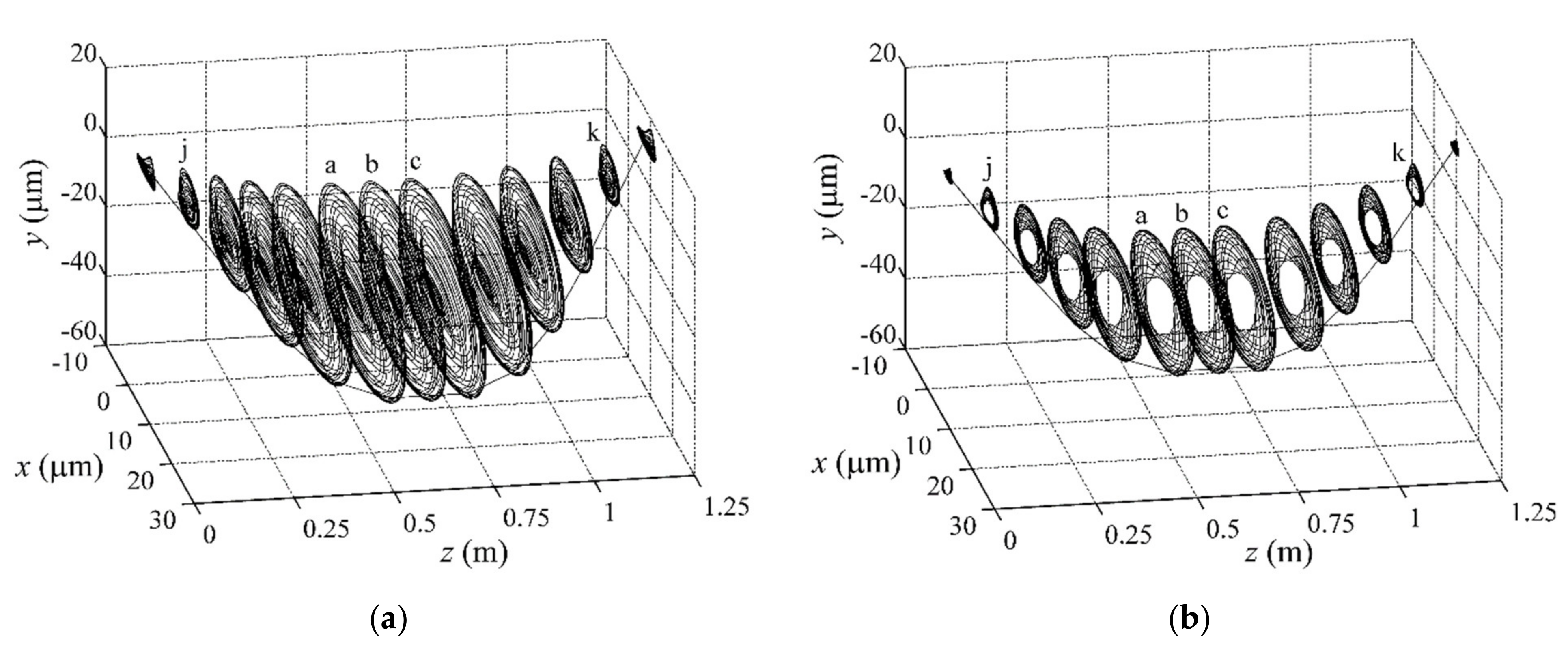
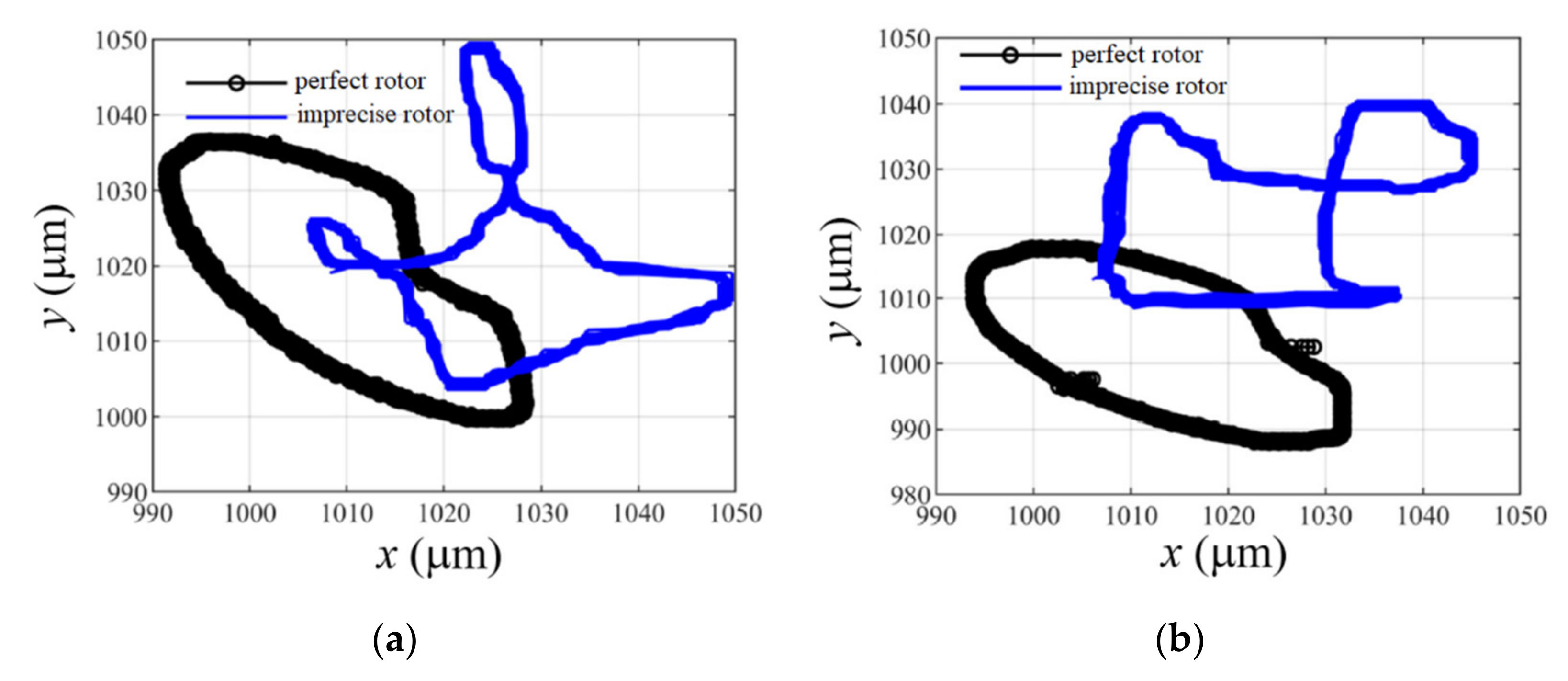
4.3. Dynamic Motions

The dynamic motions of flawed rod–disk and integral rotors are described in Figure 10. Both rotor systems perform quasi–periodic motions when the rotating speed goes through ωv (8280 r/m) and ωv’ (7940 r/m). The orbits of each selected node on axis form the dynamic motions of both rotors.
Meanwhile, the comparison of dynamic motions and corresponding Poincaré maps are shown in Figure 11. Quasi–periodic orbits ensure Poincaré points to form a closed loop.
As both orbits are identified as quasi–periodic motions, they have similar frequency components (Figure 12): working frequencies fω (fω = ω/60); Hopf semi–frequency fH (fHfω/2), which is known as fω/2 whirling; and another frequency, fQP, which comes from traditional quasi–periodic orbits. In addition, fω = 138 Hz or 132.5 Hz for rod–disk rotor or integral rotor, and fH = 76 Hz.

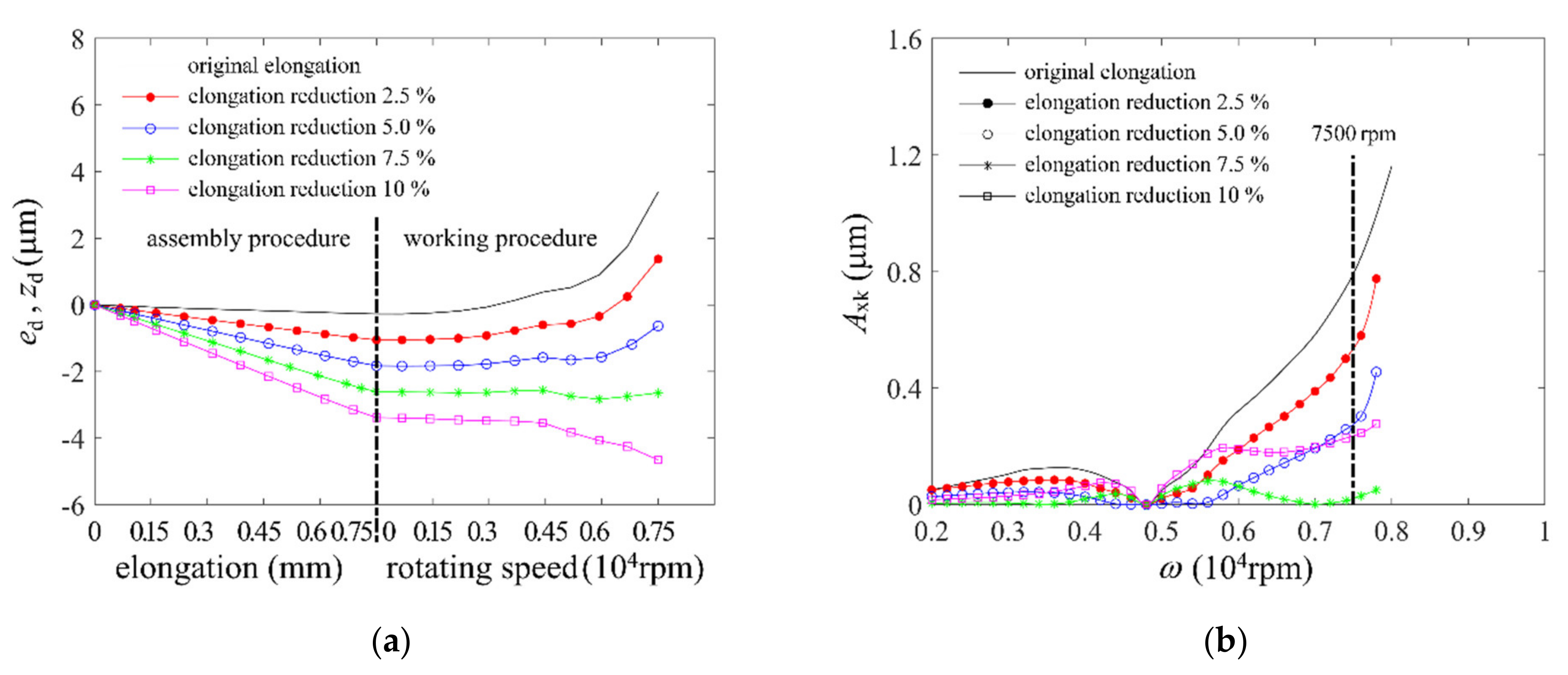
4.4. Centration Tolerance

As excessive mass eccentricity ed and rotor bending yd will result in terrible effects on the dynamics of rod–disk rotor system, the inner misalignment should be controlled to an allowable extent.
Figure 13 indicates the stability figure of both flawed rod–disk rotor and integral rotor. The curves of (ed + yd) and ed will get close to the stability boundaries of B2 and B’2, respectively, when ed and yd increase gradually.
The allowable inner misalignment is defined to make the flawed rotor always perform stable response in P area in which the rotor has periodic motions. When the inner misalignment becomes an excessive value, the flawed rotor exhibits an unstable response which includes quasi–periodic and period–doubling motions. Therefore, the maximum allowable inner misalignment will appear when the (ed + yd) curve (or ed curve) and the boundary B2 (or B’2) each have a tangency point in the speed range from 0 to 7500 rpm.
As a result, the maximum allowable inner misalignment for the flawed rod–disk rotor and integral rotor are 21 μm and 28 μm, respectively. This value can be used as a tolerance reference to design a rod–disk rotor.

4.5. Uneven Tightening

As tightening elongation is the essential reason rotor bending appears and increases, to cut its amount is a feasible way to reduce adverse effects on dynamic properties.
As Figure 2 shows, middle disk has a downward displacement and presses several rods. If the tightening elongation of No.4 rod reduces to some extent (2.5%–10%), there may be some differences.
After static–dynamic coupling analysis, it is seen that when elongation reduction ΔF equals 7.5%, rotor bending changes slightly as ω rises (Figure 14a).
This condition will make dynamic balance much easier. As a result, rod–disk rotor has the lowest vibration amplitude (Figure 14b) at working speed after dynamic balance when ΔF = 7.5%. Therefore, rotor system can also have a relatively satisfying dynamic property by uneven tightening, even if inner misalignment exists.

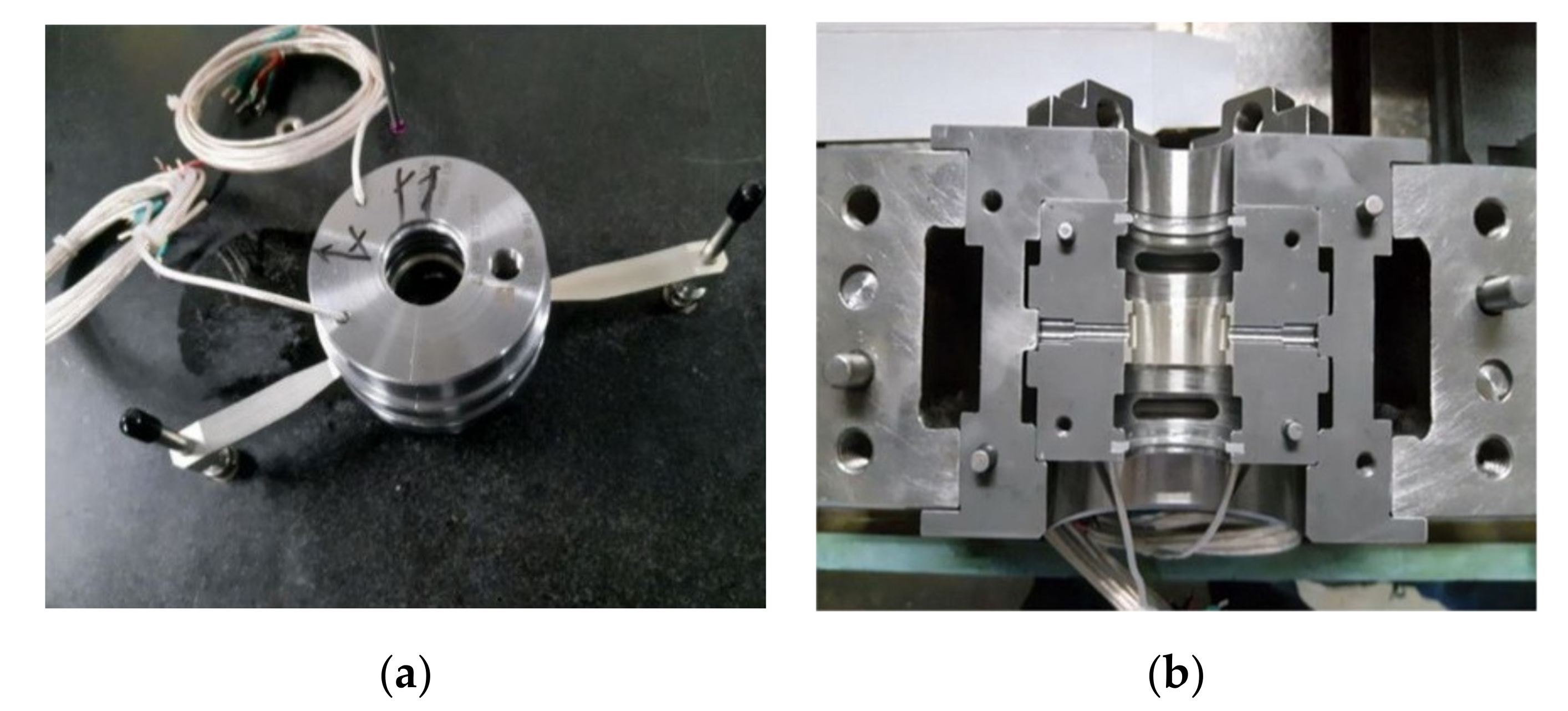
5. Experiment about the Flawed Rod–Disk Rotor System

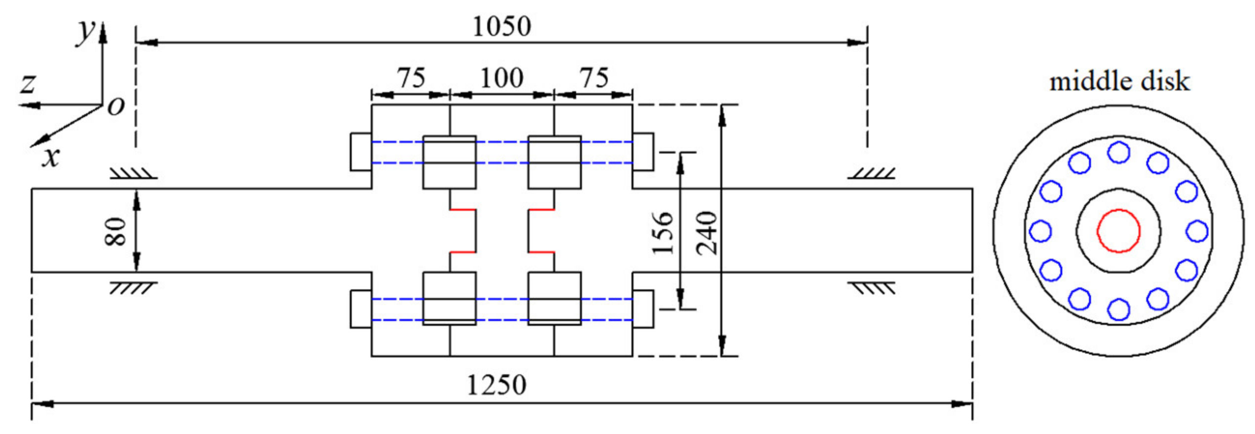
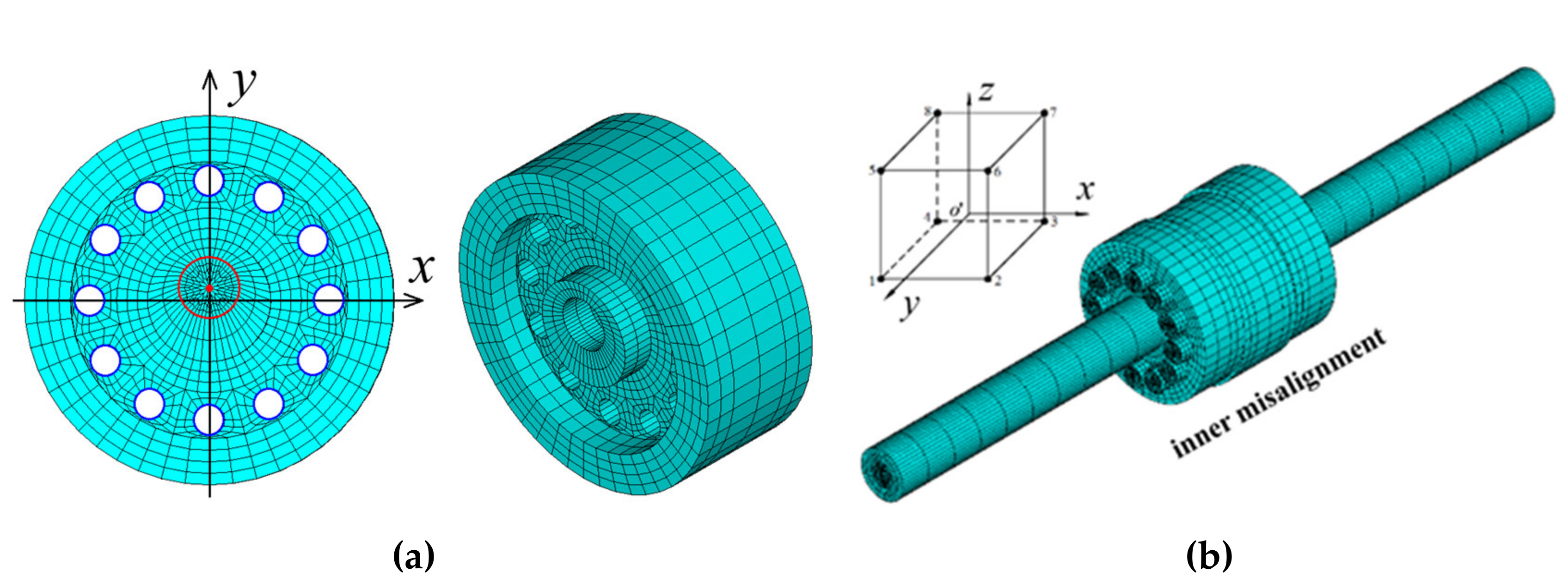
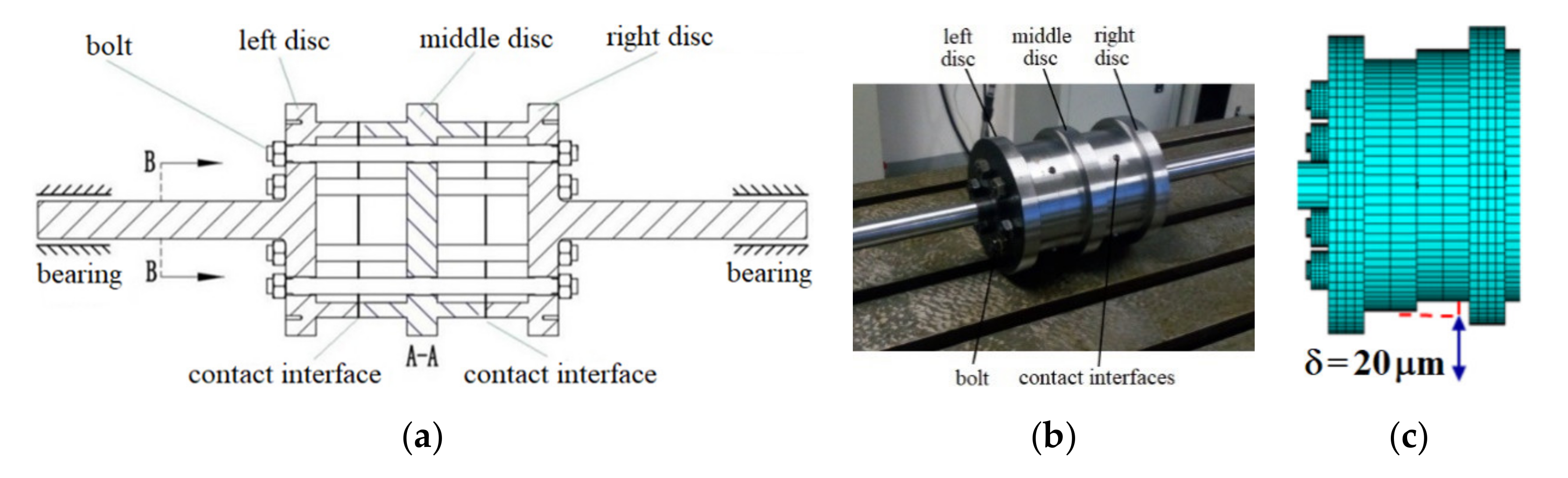
5.1. Structure and Inner Misalignment of the Rod–Disk Rotor System

Figure 15 shows the structure of the rod–disk rotor which contains three disks which are fastened by six radial–distributed rods. Every rod has the same size and elongation and rods fit against disk–holes. A 20 μm deviation between the left disk and middle disk is artificially set during the assembly process which has been magnified 1000 times in Figure 15c. Two cylindrical sliding bearings are used to support the combined rotor (Figure 16). The parameters of the shaft, rods, and bearings are shown in Table 2.

5.2. Test Rig System and Its Sensor Arrangement

The test rig system is composed of six parts (Figure 17): drive motor, coupling, bearings, rod–disk rotor, test rig base, and lubrication structure. Moreover, a series of sensors are installed and debugged to monitor the rotor state and collect test data: two pairs of electric eddy current displacement sensors (C1 and C3) are arranged at the rotating shaft near the sliding bearing to measure the displacement data and establish the whirling orbits of shaft; one pair of displacement sensors (C2) are set to measure the displacement of disk; one displacement sensor (C4) is installed facing the end of the right disk to measure the axial displacement of rotor; two acceleration sensors (A1 and A2) are installed on the bearing seats at both ends to test the vibration state of test rig; one photoelectric sensor (B) is set to measure the rotor speed; and one temperature sensor is designed to measure the temperature of bearing.

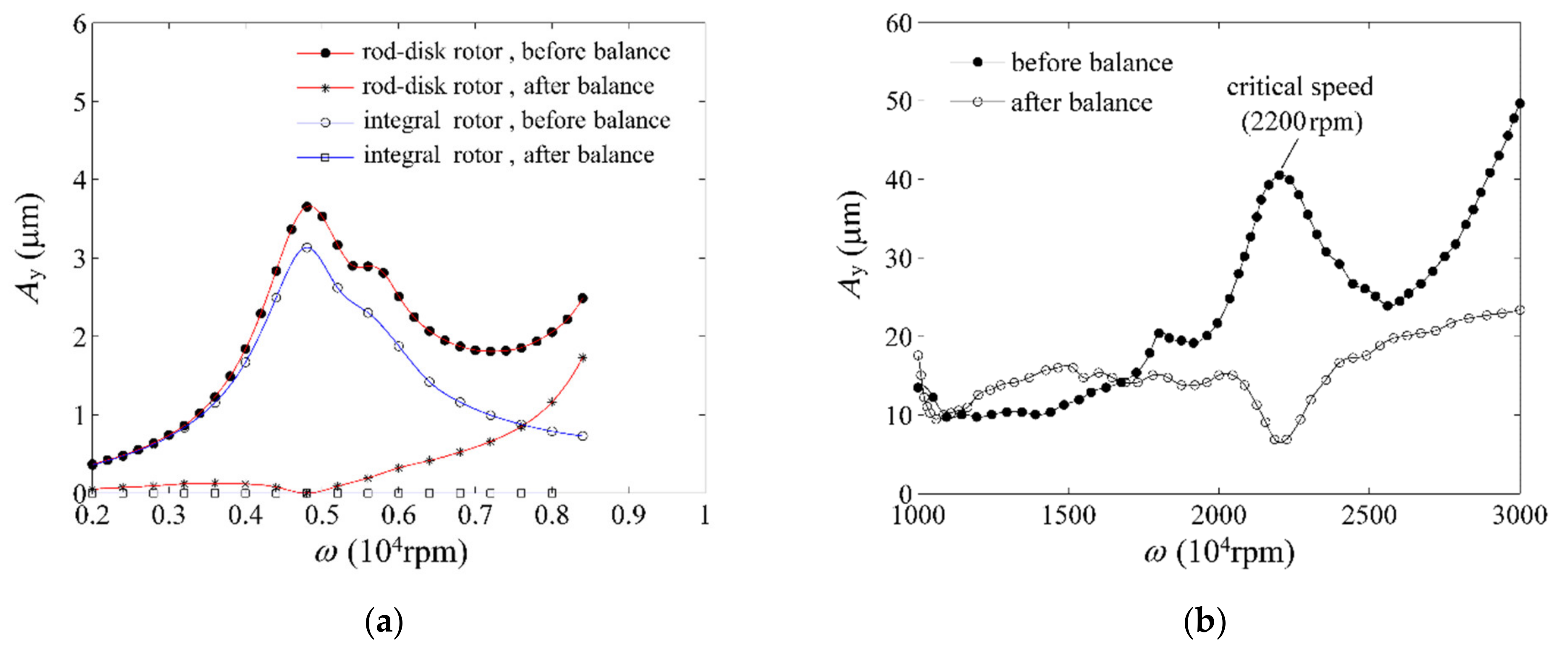
5.3. Experimental Results

Figure 18 shows that the theoretical result of vibration amplitude (at the wheel disk node) of the flawed rod–rotor bearing system is basically consistent with the experimental value when the speed increases. The result shows that the critical speed of this rod–disk rotor bearing system with inner misalignment is about 2620 rpm. The disagreement between the simulation and experimental data may stem from the calculation factor: the theoretical damping of oil film is larger than the real bearing which leads to the fact that the peak value of simulation is smaller than the experimental results; the theoretical stiffness of oil film is smaller than the real bearing, which results in the fact that the calculating critical speed is smaller than the experimental data.
Figure 19 demonstrates the whirling orbits of the precise and flawed rotor before (2250 rpm) and after (2850 rpm) the first critical speed. It is found that the precise rotor performs the periodic motion but the flawed rod–disk rotor exhibits the period–doubling orbit. This phenomenon proves that the flawed rod–disk rotor loses stability more easily than the precise rotor due to inner misalignment. Moreover, the range of period–doubling orbit is obviously larger than the periodic orbit. It shows that the flawed factor leads to large vibration for the rod–disk rotor bearing system.
The vibration amplitude in time domain and its frequency spectrum are shown in Figure 20 at 2250 rpm. Besides the main frequency (37.5 Hz), the other harmonic frequency components (such as 75Hz, 112.5hz, 150Hz, and 187.5hz) also exist for both precise and flawed rod–disk rotor bearing system. However, the amplitude of harmonic frequency components for the precise rod–disk rotor system is obviously larger than the flawed rod–disk rotor system with inner misalignment. It also proves that the error of inner misalignment can bring larger and more complicated vibration to the rod–disk rotor system.
Figure 21 shows the overall trend of the vibration amplitude within the speed range of 800~3000rpm for rod–disk rotor systems within different inner misalignments. It can be seen that the peak value of the vibration amplitude increases when the inner misalignment becomes larger. After the critical speed, the vibration amplitude decreases rapidly.

6. Discussion

In order to achieve a real rotor structure, rotor models become more and more complicated for the increasing demand of engineering application when investigating the nonlinear dynamic features of rotor system.
At first, the nonlinear models of rotor are often treated as a symmetrical rigid rotor [1,2,4,7,10] whose shaft is regarded as an absolutely rigid part and disk is regarded as a mass point. Then, the Jeffcott rotor model [8,14,19,20] is applied to analyse nonlinear dynamic problems in which the shaft’s deformation is considered and the disk is treated as a rigid part. After that, a flexible rotor model is established by introducing a 1D element such as the famous Timoshenko and Euler element [3,5,9,11,21]. Obviously, the above three kinds of simplified rotor models cannot represent the original rotor system fully and some local structures such as holes and grooves cannot be described in detail. So it will encounter difficulties when analysing the nonlinear dynamic characteristics of highly complicated rotors such as gas turbine rotor and aeroplane engine rotor. Therefore, 3D–element rotor models are built without much structural simplification [6,20,22]. However, the present 3D rotor models are integral rotors which do not have many parts to assemble together.
In comparison, the 3D rotor model presented in this paper is a complicated combined rotor which is closer to the applications in practice. On the other hand, the static–dynamic analysis process will definitely take much time to calculate, and its calculating efficiency is much lower. The comparison between other models and the proposed model in this paper is concluded in Table 3.

7. Conclusions

This paper investigates a static–dynamic solving process and an experimental test to analyse the effects of inner misalignment in a rod–disk rotor system. The conclusions include:
(1) The deviation of radial assembly surfaces causes mass eccentricity for imprecise disks; the associated inner misalignment among disks brings about rotor bending, which leads to obvious stability reduction and vibration growth; the amplitude of flawed rod–disk rotor increases again after the critical speed ωc regardless of if the dynamic balance is carried out.
(2) The maximum allowable inner misalignment of a rod–disk rotor is obviously smaller than that of an integral rotor. This shows that the centration precision should be controlled precisely to reduce inner misalignment as much as possible; moreover, uneven tightening is a feasible way to reduce adverse effects on the dynamic properties when inner misalignment appears.
(3) The theoretical result of vibration amplitude of the flawed rod–rotor bearing system is basically consistent with the experimental value. It is also found that the precise rotor performs the periodic motion but the flawed rod–disk rotor exhibits the period–doubling orbit. This phenomenon proves that the flawed rod–disk rotor loses stability more easily than the precise rotor due to inner misalignment.
The proposed static–dynamic method in this paper has wide application usage in any assembly combined rotor such as gas turbine rotor, aeroplane engine rotor, electric generator rotor, etc. In order to overcome its disadvantage of low calculating efficiency, more attention should be to rapid solving algorithms in the future.

Author Contributions

Conceptualization, Y.L.; writing – original draft, X.J. All authors have read and agreed to the published version of the manuscript.

Funding

This research was funded by the National Science Funds of China [grant number 5170051445].

Institutional Review Board Statement

Not applicable.

Informed Consent Statement

Not applicable.

Data Availability Statement

Not applicable.

Acknowledgments

We express our gratitude to all the people that have helped with this work.

Conflicts of Interest

We declare that we do not have any commercial or associative interests that represent a conflict of interest in connection with the work submitted.

Nomenclature

udisplacement vectorzddisk–center shiftKRstiffness matrix of t rotor
Qforce vectoredmass eccentricity of diskMRmass matrix
Wpotential energy due to contactydrotor bendingGRgyroscope matrix
Δpenalty factorλexcitation parameterggravity force vector
ηLagrangian multiplierfcbalance vector fboil film force
bcontact constraintsFunbalance excitation vector Ptransformation matrix

References

  1. Zhang, Y.; Fang, B.; Kong, L.; Li, Y. Effect of the ring misalignment on the service characteristics of ball bearing and rotor system. Mech. Mach. Theory 2020, 151, 103889. [Google Scholar] [CrossRef]
  2. Dal, A.; Karaçay, T. Effects of angular misalignment on the performance of rotor–bearing systems supported by externally pressurized air bearing. Tribol. Int. 2017, 111, 276–288. [Google Scholar] [CrossRef]
  3. Jin, Y.; Liu, Z.; Yang, Y.; Li, F.; Chen, Y. Nonlinear vibrations of a dual–rotor–bearing–coupling misalignment system with blade–casing rubbing. J. Sound Vib. 2021, 497, 115948. [Google Scholar] [CrossRef]
  4. Kumar, P.; Tiwari, R. Dynamic analysis and identification of unbalance and misalignment in a rigid rotor with two offset discs levitated by active magnetic bearings: A novel trial misalignment approach. Propuls. Power Res. 2021, 10, 58–82. [Google Scholar] [CrossRef]
  5. Lu, K.; Jin, Y.L.; Huang, P.F.; Zhang, F.; Zhang, H.P.; Fu, C.; Chen, Y.S. The applications of POD method in dual rotor–bearing systems with coupling misalignment. Mech. Syst. Signal Process. 2021, 150, 107236. [Google Scholar] [CrossRef]
  6. Liu, Y.; Zhao, Y.; Li, J.; Lu, H.; Ma, H. Feature extraction method based on NOFRFs and its application in faulty rotor system with slight misalignment. Nonlinear Dyn. 2019, 99, 1763–1777. [Google Scholar] [CrossRef]
  7. Abdou, K.M.; Saber, E. Effect of rotor misalignment on stability of journal bearings with finite width. Alex. Eng. J. 2020, 59, 3407–3417. [Google Scholar] [CrossRef]
  8. Srinivas, R.; Tiwari, R.; Kannababu, C. Model based analysis and identification of multiple fault parameters in coupled rotor systems with offset discs in the presence of angular misalignment and integrated with an active magnetic bearing. J. Sound Vib. 2019, 450, 109–140. [Google Scholar] [CrossRef]
  9. Sawalhi, N.; Ganeriwala, S.; Tóth, M. Parallel misalignment modeling and coupling bending stiffness measurement of a rotor-bearing system. Appl. Acoust. 2019, 144, 124–141. [Google Scholar] [CrossRef]
  10. Li, Z.; Li, J.; Li, M. Nonlinear dynamics of unsymmetrical rotor-bearing system with fault of parallel misalignment. Adv. Mech. Eng. 2018, 10. [Google Scholar] [CrossRef] [Green Version]
  11. Fu, C.; Yang, Y.; Lu, K.; Gu, F. Nonlinear vibration analysis of a rotor system with parallel and angular misalignments under uncertainty via a Legendre collocation approach. Int. J. Mech. Mater. Des. 2019, 16, 557–568. [Google Scholar] [CrossRef]
  12. Pennacchi, P.; Vania, A.; Chatterton, S. Nonlinear effects caused by coupling misalignment in rotors equipped with journal bearings. Mech. Syst. Signal Process. 2012, 30, 306–322. [Google Scholar] [CrossRef] [Green Version]
  13. Verma, A.K.; Sarangi, S.; Kolekar, M.H. Experimental Investigation of Misalignment Effects on Rotor Shaft Vibration and on Stator Current Signature. J. Fail. Anal. Prev. 2014, 14, 125–138. [Google Scholar] [CrossRef]
  14. Tapia, J.C.; Silva, J.J.; Fonseca, L.; Heredia, O.; Mata, J.L. Design of a mechatronic system for fault detection in a rotor under misalignment and unbalance. IEEE Lat. Am. Trans. 2015, 13, 1899–1906. [Google Scholar] [CrossRef]
  15. Mogal, S.P.; Lalwani, D.I. Experimental investigation of unbalance and misalignment in rotor bearing system using order analysis. J. Meas. Eng. 2015, 3, 114–122. [Google Scholar]
  16. Ma, H.; Wang, X.L.; Niu, H.Q.; Wen, B. Oil-film instability simulation in an overhung rotor system with flexible coupling misalignment. Arch. Appl. Mech. 2015, 85, 893–907. [Google Scholar] [CrossRef]
  17. Simo, J.; Laursen, T. An augmented lagrangian treatment of contact problems involving friction. Comput. Struct. 1992, 42, 97–116. [Google Scholar] [CrossRef]
  18. Wang, X.; Yamaguchi, A. Characteristics of hydrostatic bearing/seal parts for water hydraulic pumps and motors. Part 1: Experiment and theory. Tribol. Int. 2002, 35, 425–433. [Google Scholar] [CrossRef]
  19. Malgol, A.; Vineesh, K.P.; Saha, A. Investigation of vibration characteristics of a Jeffcott rotor system under the influence of nonlinear restoring force, hydrodynamic effect, and gyroscopic effect. J. Braz. Soc. Mech. Sci. Eng. 2022, 44, 105. [Google Scholar] [CrossRef]
  20. Herisanu, N.; Marinca, V. Analytical Study of Nonlinear Vibration in a Rub-Impact Jeffcott Rotor. Energies 2021, 14, 8298. [Google Scholar] [CrossRef]
  21. Shanmugam, A.; Padmanabhan, C. A fixed–free interface component mode synthesis method for rotordynamic analysis. J. Sound Vib. 2006, 297, 664–679. [Google Scholar] [CrossRef]
  22. Shen, Z.; Chouvion, B.; Thouverez, F.; Beley, A. Enhanced 3D solid finite element formulation for rotor dynamics simulation. Finite Elem. Anal. Des. 2021, 195, 103584. [Google Scholar] [CrossRef]
Figure 1. The structure (shaft, disks, rods, and bearings) and size (unit: mm) of rod–disk rotor bearing system.
Machines 10 00355 g001
Figure 2. Formation of inner misalignment and concomitant interfaces between disks.
Machines 10 00355 g002
Figure 3. Static model of rod–disk rotor with inner misalignment. (a) Model of flawed disk; (b) Model of flawed rotor.
Machines 10 00355 g003
Figure 4. Stress and deformation of rod in both rotors.
Machines 10 00355 g004
Figure 5. Contact status of rod surfaces in both rotors.
Machines 10 00355 g005
Figure 6. Disk–centre shift zd and mass eccentricity ed of the flawed disk during assembly and working procedure.
Machines 10 00355 g006
Figure 7. Rotor bending vector yd along every node location on the rotor axis.
Machines 10 00355 g007
Figure 8. Global stability areas, boundaries, and their relationships with the mass eccentricity and rotor bending for both rod–disk and integral rotor.
Machines 10 00355 g008
Figure 9. Wide–range vibration for both rod–disk rotor and gas turbine. (a) Rod–disk rotor; (b) Gas turbine rotor.
Machines 10 00355 g009
Figure 10. Quasi–periodic motions at each node on the axis for the flawed rod–disk and integral rotors. (a) Motions for the flawed rod–disk rotor; (b) Motions for the flawed integral rotor.
Machines 10 00355 g010
Figure 11. Dynamic orbits and Poincaré map for the flawed rod–disk and integral rotors. (a) Dynamic orbits for both rotors; (b) Poincaré map for both rotors.
Machines 10 00355 g011
Figure 12. The frequency components of the x–direction vibration at bearing node for the flawed rod–disk and integral rotors.
Machines 10 00355 g012
Figure 13. Maximum allowable inner misalignment which is obtained from the global stability areas for the flawed rod–disk and integral rotors. (a) Maximum allowable inner misalignment for the flawed rod–disk rotor; (b) Maximum allowable inner misalignment for the flawed integral rotor.
Machines 10 00355 g013
Figure 14. Static and dynamic properties for flawed rod–disk rotor. (a) Disk–centre shift; (b) Vibration.
Machines 10 00355 g014
Figure 15. Rod–disk rotor structure and actual picture in the experiment and rotor’s inner misalignment description. (a) Structure diagram of the rod–disk rotor in the experiment; (b) Actual rotor picture; (c) Inner misalignment δ = 20 μm.
Machines 10 00355 g015
Figure 16. Cylindrical sliding bearings which are used in the experiment. (a) The actual picture of cylindrical sliding bearing; (b) Assembly face of the cylindrical sliding bearings.
Machines 10 00355 g016
Figure 17. The structure, sensor arrangement and actual picture of the test rig. (a) Test rig composition and sensors arrangement; (b) Actual picture of the experimental setup.
Machines 10 00355 g017
Figure 18. Test vibration amplitude of the imprecise rod–disk rotor bearing system. (a) Simulation result; (b) Experimental result.
Machines 10 00355 g018
Figure 19. Whirling orbits for the perfect and imprecise rod–disk rotor before and after the first critical speed. (a) 2250 rpm; (b) 2850 rpm.
Machines 10 00355 g019
Figure 20. Amplitude in time domain and frequency spectrum for the both rod–disk rotor bearing system. (a) Amplitude in time domain; (b) Frequency spectrum.
Machines 10 00355 g020
Figure 21. The vibration amplitude for the rod–disk rotor systems within different inner misalignments. (a) X–direction vibration; (b) Y–direction vibration.
Machines 10 00355 g021
Table 1. Parameters of bearings and rods.
VariablesValue
Bearingsbearing diameter80 mm
bearing width80 mm
radial clearance0.18 mm
oil lubricant viscosity0.018 Pa⋅s
Rodsnumber of rods12
length of rods250 mm
diameter of rods10 mm
elongation750 μm
Table 2. Parameters of rod–disk rotor bearing system.
PartParameterValue
RotorDiameter of shaft25 mm
Length of shaft900 mm
Diameter of disks154 mm
Length of left disk50 mm
Length of middle disk80 mm
Length of right disk50 mm
Number of rods6
Length of rods205 mm
Diameter of rods10 mm
Elongation200 μm
Diameter of circumference for rods88 mm
BearingsBearing diameter25 mm
Span of bearing771 mm
Bearing width15 mm
Radial clearance200 μm
Oil lubricant viscosity0.018 Pa⋅s
Table 3. The comparison between different rotor models.
Types of ModelStructureElementDOF NumberAdvantageDisadvantage
rigid rotor modelrigid shaft and disksmass pointfew1. can describe basic dynamic features;
2. has high calculating efficiency
1. has over structure simplification;
2. has obvious difference with real complicated rotors
Jeffcott rotor modelflexible shaft and rigid disksbeam element
1D rotor modelflexible shaft and rigid disksbeam elementsome
integral 3D rotor modelflexible shaft and disks3D elementlargecan describe integral rotor structure fullycannot consider assembly process
combined 3D rotor modelflexible parts are combined3D element1. can describe integral rotor structure fully;
2. can consider assembly process
has low calculating efficiency
Publisher’s Note: MDPI stays neutral with regard to jurisdictional claims in published maps and institutional affiliations.

