1. Introduction
The power of electrical drive applications ranges over several orders of magnitude [
1]. Accordingly, cooling requirements also depend on the specific use case. Various cooling systems for electric motors have been presented in the literature. Among them, the closed-loop forced liquid cooling offers the best thermal performance compared to open- or closed-loop forced air cooling [
2,
3,
4]. In general, such topologies can be categorized according to the primarily cooled machine part into stator, shaft or end-winding cooling concepts.
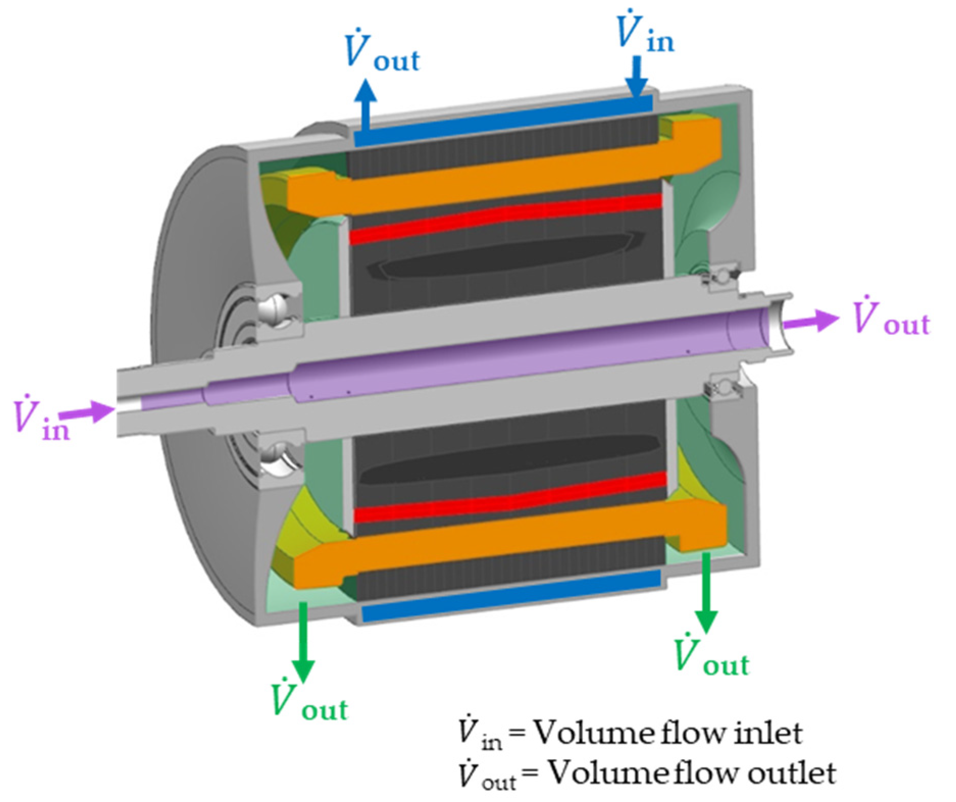
Figure 1 illustrates the inlets and outlets of the coolant in a permanent magnet synchronous machine (PMSM) along with the cooled surfaces.
Stator jacket cooling (blue) with water ethylene glycol (WEG) or oil
Rotor shaft cooling (magenta) with WEG or oil
Interior end winding cooling (green) with oil
Each of the cooling concepts can be designed in different ways when it comes to the cooling channel geometry of stator jackets or the coolant distribution of the end winding cooling, for example [
2]. Simulation of end winding cooling is the most challenging because of the complex distribution of fluid and air. Therefore, test bench measurements are particularly important for this concept in order to properly model heat flow across the affected surfaces [
5]. For thermal optimization during the design process, it is crucial to understand the effects of the different heat dissipation methods. The literature, however, usually concentrates on a single use case or cooling concept. Investigations are then limited to the volume flow rate [
6], the impact of the cooling jacket channel geometry [
7,
8] or a combination of both [
9,
10].
More holistic thermal sensitivity studies, on the other hand, do not compare different cooling concept combinations but rather focus on parameters such as thermal conductivity, thermal contact resistance and convection inside an enclosed machine [
11,
12] or concentrate on a fixed cooling concept [
13,
14]. This does not, however, adequately cover all of the versatile influencing parameters: In addition to the combination of cooling concepts, the thermal designer must calculate the optimum geometry of the cooling system and choose the volume flow rates in order to find the best compromise between heat transfer, energy consumption of the coolant pumps and complexity of mechanical integration. Differing from other contributions, the presented study investigates the influence of volume flow rates, cooling fluids and combinations of the cooling concepts introduced in
Figure 2. In addition to convective heat transfer analysis, parameters such as machine length and rotor properties are part of the sensitivity analysis that aims at describing impact on the heat dissipation capability of a PMSM. The proposed method and the specific results enable a comparison of different cooling concepts under various conditions and thus provide a guide for thermal machine design.
A measure of the effectiveness of the heat extraction from the electrical machine is the continuous power that can be achieved without exceeding temperature limits [
15].
Figure 2 shows the relative peak and continuous power of a permanent magnet synchronous machine. In this example, the machine can only be operated continuously at around half its maximum power. At low speeds, the stator windings limit the performance, whereas at high speeds, the magnets would exceed their temperature limits at high power operating points. Accordingly, in order to improve continuous performance in the respective regimes, the designer must know the main levers for improving heat extraction from these specific machine parts. For this contribution, a thermal model of an electric motor is developed that includes several stator, shaft and end winding cooling concepts. After establishing confidence in the model by means of test bench data, several sensitivity analyses are performed to show the dependence of the continuous machine power for different combinations of cooling systems, volume flow rates and rotor parameters. Additionally, the influence of machine length on thermal performance in general and the effectiveness of the different cooling concepts as a function of length are demonstrated. Sensitivity analysis for electrical machines is often performed by means of scaling a well-known design [
16,
17]. In particular, a change in the length of the machine is easy to evaluate since both electromagnetic and thermal impacts are linear and therefore can be accounted for by analytical methods. The effect on the thermal behavior, however, must take into account several effects. Both stator and rotor cooling surfaces are directly proportional to the length, and the heating of the cooling fluid along the flow path must be taken into consideration. Conductive heat transfer is also linearly dependent on the length whereas the heat transfer coefficient of the end windings is independent.
Since the same torque can be generated with less current, the dissipated heat is typically reduced if the machine’s length increases while the winding configuration remains the same.
Figure 3 illustrates different machine designs for specific applications. Typically, machines for pure electric vehicles have small diameters and are longer than machines for hybrid electrical vehicles due to different speed and torque requirements. Depending on the boundary conditions, the length ranges from a few centimeters, e.g. in hybrid electric vehicles, to close to 20 cm for pure electric applications [
18,
19,
20]. This underlines the importance of understanding the behavior of each cooling concept for different machine types.
2. Thermal Model for Electrical Machines
A widely popular method for thermal investigations in the field of electrical machines is the use of lumped parameter models [
21]. Among their benefits are low computational effort, scalability and adaptability. The thermal simulation in this contribution makes use of these qualities. The governing equation
that describes the stationary temperature distribution for each node
is a function of losses
, cooling fluid temperature
, mass
, heat capacity
, thermal conductivity
, cross-section
and length
between neighboring nodes
and
, as well as heat transfer coefficient
. Sources of error are simplifications necessary to describe complex geometries, convective heat transfer modeling and the exact determination of the loss distribution. An automated CAD import developed for the presented method minimizes the uncertainties concerning the representation of the geometry. Test bench data are used to validate the electromagnetic loss models. The algebraic representation of the convective heat transfer, on the other hand, is based on well-proven Nusselt correlations.
Figure 4 shows a simplified example of a lumped parameter model and the respective machine parts. Nodes 1, 2, 4 and 6 represent convective heat transfer to the cooling fluid or within the air gap. In the actual model, all components are divided into several nodes along the three special dimensions so that the model is comprised of more than 200 grid points. Main electromagnetic loss sources are the stator iron, the stator windings, the rotor iron and the magnets. They are included in the simulation as heat sources in the respective machine parts according to their local distribution that results from the electromagnetic simulation. Additionally, mechanical losses due to friction are considered at the bearings and in the air gap.
If only air is inside the machine around the winding heads, the convective heat transfer is a function of the air velocity
in the end space
where the coefficients
,
and
differ slightly between different sources like [
22,
23,
24], but overall give similar results. The air gap convection is equally difficult to describe but has been covered by several authors, as summarized by reviews like [
25,
26]. The Nusselt correlations depend on the Taylor number
with the angular velocity
, the inner stator radius and outer rotor radius
and
, as well as a geometry factor
that also accounts for the shape of the stator near the air gap. The convective heat transfer at low Taylor numbers can be described as
and, therefore, is only a function of the geometry, whereas at
, the Taylor number increases in influence
Even higher rotational speeds result in different coefficients, giving
The Nusselt number itself is defined as
using the characteristic length
and the thermal conductivity
. The definition of the characteristic length depends on the application. For regular round ducts, the characteristic length is represented by the channel diameter.
Inside the rotor shaft, heat is transferred to the coolant that flows axially and has superimposed velocity components due to the rotation of the shaft. Seghir-Oualie et al. [
27] conclude that in the literature, both enhancing [
28,
29] and reducing [
30,
31,
32] effects of rotation on turbulence are reported. The authors derive the correlation
where
is the axial Reynolds number and
is the rotational Reynolds number, with
being the axial fluid velocity,
the shaft diameter,
the kinematic viscosity and
the rotational speed.
In the stator cooling jacket, heat transfer calculated based on the work of Gnielinski [
33]:
with
being the resistance factor,
the Prantl number,
the channel diameter and
the length of the channel. The convective heat transfer at the different heat sinks depends on the volume flow rate, except for the cooling jacket also on the speed of the machine. With the help of test bench measurements, the applicability of the equations above is validated and deviations between measurement and simulation are minimized by means of the least square method and a fitting factor. In this way, the convective heat transfer phenomena considered in this contribution are validated, and an accurate prediction of the thermal behavior is ensured. All three heat sinks are combined in different ways in order to compare their influence on the continuous power of the electric machine.
3. Validation of the Reference Machine
In order to validate the thermal model of the electrical machine, two test benches are set up. The first experiments focus on the stator cooling jacket with WEG and oil, whereas the second is a test bench for electrical machines.
Figure 5a shows the test bench for the stator cooling jacket. The specimen consists of the cooling jacket, the stator of the electrical machine and eight heating cartridges that serve as a heat source at the inner surface of the stator. This setup allows an exact control of the energy that enters the system and is ultimately transported to the environment through the cooling jacket. Insulation around the specimen minimizes heat loss due to natural convection or radiation. At the inlet and outlet of the cooling channel, several sensors measure the temperature, pressure and volume flow rate of the coolant. Additionally, eight PT100 sensors measure the temperature distribution within the specimen. The thermal model of the WEG and oil-cooling jacket is validated against the respective experiments with different input power, volume flow rates and coolant inlet temperatures. After establishing confidence in the cooling jacket simulation, the model of the entire electrical machine is compared to the experimental results of a second test bench, see
Figure 5b. The electrical machine is equipped with 40 thermocouples of type K that are distributed in the stator iron, the windings, the rotor and the magnets. The volume flow rate and inlet temperatures of the cooling jacket as well as the shaft and end winding cooling are controlled.
Figure 6a shows the results of the cooling jacket simulation validation on the test bench. For both the WEG and the oil-cooling jacket the normalized heat flow is depicted for different volume flow rates. The diagram shows only one of several temperature boundary conditions that are investigated for the validation of the model. For each boundary condition, multiple measurements are carried out. The mean value and the range of the results from the test bench are depicted at different volume flow rates. The simulated data match the measurements and are given with the solid and dashed line for the WEG and oil cooling concept, respectively. With increasing coolant flow rate, the heat transfer coefficient increases; so does the heat flow
, but with a decreasing gradient. After the validation of the cooling jacket simulation, the thermal model of the electrical machine is compared to test bench data. The validation of the electromagnetic model is not part of this contribution; the loss distribution within the machine is known for every operating point. For different combinations of coolant flow rates in the cooling jacket, the rotor shaft and the end winding space, several operating points are measured in continuous operation. A coefficient for the rotor shaft heat transfer coefficient and the end winding heat transfer coefficient is derived from the measurements that minimize the deviation of measurements and simulation.
In order to validate the resulting model, the continuous power is determined by increasing the torque for various speeds until the temperature limit of the machine is reached in a steady state for different coolant flow rates and inlet temperatures.
Figure 6b compares two simulated continuous torque curves against the corresponding measurements and shows that they are in good agreement. One case depicts a cooling concept with a water-cooling jacket, and the other depicts a concept with an oil-cooling jacket. The error bars of the measured data represent the measurement inaccuracy of the torque sensor and the temperature sensors.
4. Comparison of Cooling Concepts for the Reference Machine
The reference machine is suitable for medium power full electric vehicle drivetrains. In order to achieve a high continuous power, the cooling concept comprises both a cooling jacket as well as rotor and end winding cooling. As the end winding cooling is connected serially to the rotor shaft cooling, it cannot be applied without an equal coolant flow in the rotor. On the other hand, shaft cooling without end winding cooling is possible with a bypass. The standard layout of the cooling system comprises all three heat sinks and oil cooling. This concept is compared to a WEG cooling jacket, WEG shaft cooling and different volume flow rate combinations in this contribution. The maximum machine speed exceeds ; however, graphs in this contribution don’t show higher speeds since the effects of interest are already apparent below.
The validated model of the electrical machine allows the comparison of different cooling concepts and volume flow rates. The cooling concepts and the electrical machine are not optimized in these studies, and rather than the absolute values, this contribution discusses the relative influences of thermal design on continuous power. In the first sensitivity study, different oil cooling scenarios are compared. In all scenarios, the total volume flow rate is
and the inlet temperature is the same. The aim of the investigation is to outline the impact the distribution of the volume flow rate between the three heat sinks: stator cooling jacket, shaft cooling and end winding cooling.
Figure 7 shows the relative continuous power for four different coolant distributions. Owing to the concept of the machine, the end winding cooling always implies a rotor shaft cooling with the same volume flow rate. The lowest continuous power is achieved when only the stator cooling jacket is active. Due to inefficient cooling of the rotor, the permanent magnet temperature limits the operation to speed ranges below
for steady state operation. An equal distribution of the volume flow rate between the shaft and the cooling jacket improves the rotor cooling. Consequently, continuous power increase, especially at high machine speeds where
is achieved. For low speeds, the decrease in thermal performance due to a reduced stator cooling can be neglected, from which it can be derived that the effect of the cooling jacket is already saturated at
. Due to improved heat dissipation from both the rotor and stator, a further increase in continuous power with the same total volume flow rate is achieved if the end winding cooling is active.
Since copper losses account for a large proportion of the losses, the direct cooling of the windings is more effective than other cooling concepts. Even without the stator cooling jacket being active, cooling the end windings and the rotor shaft results in a continuous power of more than 55% of the peak power. The best thermal performance, however, results when all three heat sinks are applied. With this concept, the heat sinks are evenly distributed in the machine and thermal resistance due to conduction is minimized. Besides oil cooling, a mixture of water and ethylene glycol (WEG) is also commonly used for electrical machine cooling [
3]. As WEG is part of the electric vehicle cooling circuit, the motor can easily be integrated, for example, after the power electronics cooling heat sink. Furthermore, water has superior physical properties as a coolant compared to oil with regard to specific heat capacity or thermal conductivity. However, direct contact with active machine parts has to be prevented mainly due to electric properties and corrosion protection. This leads to additional effort and required space for the design of the cooling jacket. Additionally, direct end winding cooling is not possible with water-based coolants.
Figure 8 compares water cooling to oil cooling for different volume flow rates. The graphs depict the normalized continuous power with
,
and
equally distributed between the stator cooling jacket and the shaft and in the case of oil cooling also the end winding, respectively. WEG cooling with the same total volume flow rate has a considerably lower continuous power. The additional heat sink at the end windings offsets the disadvantages of oil with respect to its physical properties. Differences in physical properties are also mitigated by the fact that in the oil-cooling jacket, the coolant is in direct contact with the stator iron as opposed to the WEG cooling jacket, which has an additional housing between stator and coolant. These findings, however, can change for a different electromagnetic design if the cooling jacket becomes more decisive due to increased iron losses, for example. The results indicate a minor sensitivity with regards to the volume flow rate in the case of WEG compared to oil. This is related to the high thermal capacity of WEG even at small volume flow rates. Additionally, the overall thermal resistance between heat sources and heat sinks is higher with water cooling than with oil cooling. Therefore, the significance of the convective heat transfer is less crucial compared to oil cooling systems according to the findings in this study. The oil heat sink at the shaft combined with direct cooling of the end windings is more effective in terms of continuous power. This topology achieves a better performance than the WEG concept even with the lowest volume flow rate.
5. Comparison of Different Machine Lengths
The aforementioned investigations were all performed with the same machine that has a peak power in the range of 200 kW. Hereinafter, three of the cooling topologies are compared for a machine with half the length
that has a power of about 100 kW and one with
more length
that has a power of about 300 kW. The comparison considers the continuous power relative to the peak power of the respective machine. Accordingly, for the absolute values, the power class of each machine has to be taken into account.
Figure 9 shows the results for the shortest machine on the left (a), the reference machine in the middle (b) and the longest machine on the right (c). A WEG stator jacket and shaft cooling with
each, a shaft and end winding cooling with
and a combination of oil stator jacket with
as well as shaft and end winding cooling with
are compared. The results show that the effect of the WEG stator jacket’s cooling increases with machine length, which can be related to the increase in the surface that is in contact with coolant as well as with an increasing significance of the electromagnetic iron losses. A stator jacket is suitable for machines with high stator iron losses since it is close to the heat source. However, the maximum relative continuous power across all machines is
for water cooling. Direct oil end winding cooling combined with shaft cooling results in higher continuous performance, especially for short machines. Almost twice the continuous power of the WEG topology is achieved even without a cooling jacket. For increasing machine lengths and therefore higher iron losses, the benefit decreases until it is almost negligible for the longest machine. The hot spot of machines without stator cooling jackets usually is in the center of the stator, and the thermal resistance between this location and the end winding cooling increases with machine length. Thus, a reduction in shaft and end winding cooling in favor of an oil-cooling jacket further increases continuous power in all scenarios. The overall trend for oil cooling is that the percentage of the peak power that can be utilized continuously decreases with the length and performance category, respectively. However, with the equal distribution of oil heat sinks still results in more than
of the peak power in the largest machine compared to over
for the smallest one. It must be noted that the findings discussed above refer to relative differences in continuous power. Taking into account the increase in peak power with the machine length, the absolute values of continuous power also increase.
6. Rotor Sensitivity Study
Owing to a low temperature limit of the permanent magnets, rotor cooling of a PMSM is of particular importance. With increasing temperature, the magnetic properties decrease. Furthermore, for the widely used neodymium–iron–boron (NeFeB) magnets, a temperature of around
can already bear the risk of demagnetization in case of unfavorable external magnetic fields that can result from machine faults [
34]. High amounts of rare earth metals can improve resilience against demagnetization but are expensive, and their magnetic properties deteriorate [
35,
36]. In conclusion, a suitable cooling strategy can improve the overall design of the rotor. Heat extraction is particularly affected by the following factors:
Coolant volume flow rate and distribution;
Magnet temperature limit;
Magnet thermal contact resistance;
Rotor iron losses;
Coolant inlet temperature;
Thermal conductivity of the rotor and the magnets;
Shaft thermal contact resistance;
Air gap heat transfer.
Volume flow rate and coolant distribution have been extensively discussed in the previous chapter. In this section, the contribution of parameters 2–5 is further investigated.
Figure 10 shows a part of the cross-section of an exemplary PMSM and illustrates the position of these four influencing factors except for the coolant inlet temperature. For the study, a machine whose continuous performance is considerably limited due to the rotor is studied. The rotor design’s is different from that of the machine discussed above, but the validity of the thermal simulation is not affected by these changes since the geometry inside the rotor is taken into account and convective heat transfer is identical. The risk of rotor overheating in general increases with high rotor losses and is more pronounced for designs with many magnets, such as double-V or delta magnet arrangements, since heat extraction becomes more challenging with several layers of magnets.
Figure 11 shows the results of the sensitivity study for the reference machine and an improvement of the investigated parameters of
. The black line with square markers depicts the normalized continuous power of the reference cooling design with oil-jacket cooling as well as shaft and end winding cooling. The volume flow rate is constant in all simulations. At approximately
, continuous power decreases due to the limitation of the magnet temperature as a consequence of increasing losses in the lamination and the magnets. However, the study shows that the rotor losses themselves only have a limited effect on the continuous performance since a decrease of
does not improve continuous power significantly compared to other measures. A decrease in the thermal contact resistance at the magnet surfaces results in slightly better heat extraction, but continuous power is even more sensitive to the magnet temperature limit. At
, the improvement is almost 20 percentage points. The greatest influence can be observed for a decrease in the coolant inlet temperature, and in contrast to the other measures, the continuous performance is also improved at lower speeds at which the stator limits the operation. In conclusion, overall thermal management must be investigated thoroughly in order to achieve beneficial inlet temperatures at each component. If no design changes are available, an increase in the amount of rare earth metals in the magnets can considerably improve thermal behavior. In general, a holistic optimization of all parameters is necessary in order to achieve the required continuous power with the least expense. The results aid in understanding the tools that can be used along with general machine design and the optimization of cooling topology.
7. Conclusions
In this contribution, the influence of several parameters on the continuous performance of a PMSM is studied. The first analysis was dedicated to different volume flow rate combinations in the cooling jacket, the shaft, and at the end winding for water and oil cooling for the reference machine. For an equal volume flow rate in similar heat sinks, the water cooling was beneficial compared to oil cooling due to better physical properties. However, the direct end winding cooling with oil is an effective measure to extract heat generated in the windings which are one of the main loss sources in the machine. Therefore, the highest continuous power is achieved when this cooling concept is included. In the system design, the complexity of the mechanical integration and the additional friction losses due to the end winding cooling must be taken into account. A second study showed that this result is still valid for different machine lengths, though the effectiveness of the heat sinks varies. In short machines, the cooling jacket has a small surface and is less efficient than in long machines. At the same time, iron losses increase with the machine length, and therefore, a sole use of end winding cooling for the heat extraction becomes less effective. In general, the ratio of continuous power to peak power decreases with machine size even though the absolute continuous performance increases. In a final study, different options to improve continuous performance at high machine speeds, when the rotor is the limiting component, are discussed. The results show that the effectiveness of the different measures increases in the following order: reduction of rotor losses, improvement of the magnet fixation in the rotor, increase of the magnet temperature limit and reduction of coolant inlet temperature. While the inlet temperature leads to the highest increase of the continuous power and also improves the performance when the stator is the limiting machine part, the rotor losses and the magnet fixation show only minor influence. The magnet temperature limit is among the parameters that can be influenced most easily by adding rare earth metals; however, this implies higher cost and reduced electromagnetic performance.
The results of this contribution can serve as a guideline for the thermal design of PMSMs. Even though the investigations are based on a permanent magnet synchronous machine for automotive applications, the results can be transferred to other use cases and machine types to a large extent. Ultimately, the benefits and disadvantages of the available measures must be evaluated for every application with regards to mechanical feasibility, continuous power requirements or cost, for example. In future investigations, different diameters or special boundary conditions such as ambient pressure will be investigated by the authors. Additionally, FEM simulations can be used to further improve the calculation of thermal resistances.


