Abstract
To solve the problem of tension stress caused by centrifugal force and caused by high-speed operation of permanent magnet (PM) rotor, a FeCo-based PM rotor structure model is proposed. Based on the thick-walled cylinder theory, the uniform analytical calculation formulas of strain field, displacement field, and stress field of high-speed permanent magnet rotor are derived, and the stresses of FeCo-based PM and sleeve are obtained. The correctness of analytical calculation method (ACM) is verified by finite element method (FEM). Based on the derived analytical formula, the influence of static interference, sleeve thickness, rotating shaft, and PM thermal expansion coefficient on the strength of high-speed permanent magnet rotor is analyzed, and the mechanical design law of high-speed permanent magnet rotor is summarized. Alloy sleeves are usually fitted outside the high-speed permanent magnet rotor to protect the PM from damage. In order to ensure safe operation of PM rotor under hot rotating conditions, strength calculation and check of sleeve and PM must be carried out. Based on the characteristics of slender structure of high-speed rotor, a high-speed permanent magnet motor (HSPMM) with a rated power of 100 kW and a rated speed of 18,000 r/min was produced, and a continuous operation test was carried out to verify the validity of the above theoretical analysis.
1. Introduction
HSPMM has excellent performance of high power density, small volume, and high efficiency, and its rotor strength has always been an important problem restricting its development [1,2]. When the high-speed motor is running, all parts of the rotor are subjected to huge centrifugal force, so the surface mounted permanent magnet rotor structure with rotor sleeve is often used [3] to ensure the safety of the PM. Common rotor sleeve materials mainly include high-strength metal materials (such as titanium alloy and Inconel alloy) and high-strength composite materials (such as carbon fiber, glass fiber, and aramid fiber) [4,5]. Their physical properties are very different: the metal sleeve has good conductivity and large eddy current loss in the sleeve, but its thermal conductivity is high, and the rotor is easy to dissipate heat. The conductivity of the fiber sleeve is very low, and there is almost no eddy current and loss in the sleeve, but its thermal conductivity is poor, and it is difficult for the rotor to dissipate heat. Therefore, the sleeve material has a significant effect on the eddy current loss and temperature rise of the HSPMM rotor.
Scholars at home and abroad have carried out a lot of research work on the strength of high-speed rotors [6,7,8]. Based on the finite element analysis model, in [9,10,11,12], the author has studied the influence of sleeve thickness and interference on rotor stress by using the parametric method, and determined the sleeve parameters accordingly. In view of the difficulty in selecting the rotor parameters of high-speed motor, in [13] the author uses the finite element method to comprehensively consider the effects of material anisotropy and centrifugal force and proposes a set of optimization design methods for HSPMM rotor based on multiphysical field coupling. The deficiency of the above methods is that for the size of the sheath and PM, it is necessary to optimize the sleeve thickness, interference, and other parameters, and the calculation is mostly based on the finite element model, so the design method based on the stress analysis model will be used in this paper to improve the calculation efficiency. In [14] the author also used the finite element method to calculate the strength of the HSPMM rotor but did not carry out in-depth calculation of the rotor strength. In [15], they added a glass fiber layer between the sleeve and the PM to solve the problem of bending stress at the contact of the sleeve. At the same time, the ACM and the FEM were used for comparative analysis to verify the correctness of the structure. In [16], the author further studied the rotor strength under the coupling of multiple physical fields. For an HSPMM with a rated power of 10kW and a rated speed of 120kr/min, in [17] the author derived the analytical formulas of the stress field, strain field, and displacement field of the HSPMM rotor under different assembly methods, and verified the accuracy of the ACM through the FEM. However, the reference ignored the influence of temperature on the rotor stress. In [18], the analytical formulas of stress field and displacement field of high-speed solid PM rotor are derived, and the correctness of the ACM is verified by using the FEM. In [19], the rotor strength variation law of high-speed surface mounted PM synchronous motor with inter pole filler block was analyzed by ACM and FEM, respectively. For three-layer and two-layer rotor structures, the stress analytical model of isotropic material rotor is derived in [20,21]. For the PM solid rotor structure with alloy sleeve, in [22], the author established a stress analysis model and directly calculated the sleeve interference with critical contact pressure between the sleeve and the PM on the premise of knowing the sleeve thickness. In [23], the author established an analytical model of rotor stress, compared the rotor stress distribution under four kinds of sleeve materials and two kinds of PM materials, and designed the sleeve size of each rotor.
In the previous ACM of rotor strength, the influence of rotor working temperature should be further considered. Because it is very difficult to measure stress and strain at high-speed, the theoretical prediction of high-speed annular PM rotor strength is an economical and feasible method to guide the mechanical design of high-speed permanent magnet rotor. According to the slender structural characteristics of high-speed annular permanent magnet rotor, based on the thick wall cylinder theory, this paper deduces the analytical calculation formula of high-speed permanent magnet rotor strength considering the rotor working temperature. Using the FEM, the rotor strength of a HSPMM with rated power of 100 kW and rated speed of 18,000 r/min is analyzed under steady, cold, and hot rotating conditions. The correctness of the ACM is verified by finite element analysis and experiments. At the same time, combined with the ACM, the influence of different factors on the mechanical strength of the rotor is analyzed, and the design law of the rotor of HSPMM is summarized.
2. Analytical Calculation of Rotor Structure and Rotor Strength of HSPMM
2.1. Rotor Structure of HSPMM
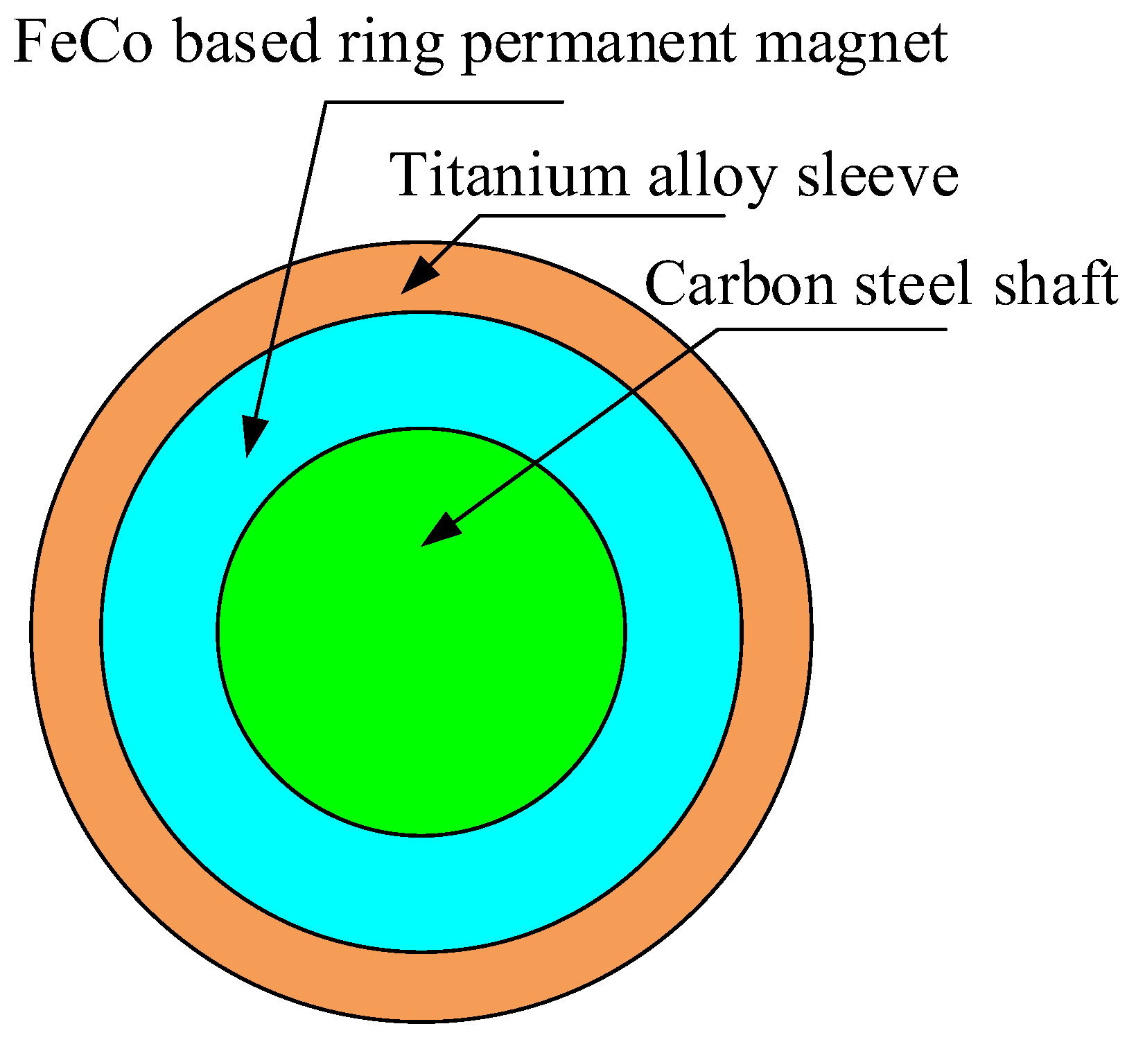
The rotor structure of HSPMM is simple, which is mainly composed of rotor shaft iron core, PM, and titanium alloy sleeve. The PM adopts FeCo-based PM. The structure model of motor rotor is shown in Figure 1, and the material properties of each part of the rotor are shown in Table 1.

Figure 1.
Rotor structure of HSPMM.

Table 1.
Rotor material performance parameters.
2.2. Analytical Calculation of Rotor Strength of HSPMM
The rotating shaft, FeCo-based PM, and titanium alloy sleeve of HSPMM are circular. According to the classical thick wall cylinder theory, the strength of FeCo-based PM rotor is analyzed and calculated, the outer radius of rotor core is set as Ror, and the inner and outer radius of PM are Rim and Rom. The inner and outer radius of titanium alloy sleeve are Rit and Rot, the rotor dimension is shown in Figure 2a, and the interference between PM and titanium alloy sleeve is δ. PM is in binding contact with the rotor core, and the interference is 0.
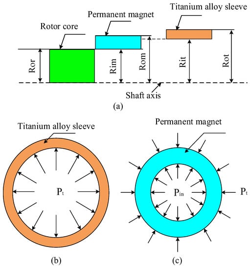
Figure 2.
Rotor system. (a) Rotor size marking, (b) Force analysis of sleeve, (c) Force analysis of PM.
The stress of titanium alloy sleeve is shown in Figure 2b. Firstly, it is assumed that the contact pressure of the contact surface between the rotor core and the PM is Pin, the contact pressure of the contact surface between FeCo-based PM, and titanium alloy sleeve is Pt. On this basis, the stress differential equations of titanium alloy sleeve and PM are solved, respectively, and the analytical solutions of stress and displacement of each part of the rotor are obtained.
According to the theory of elasticity, the equilibrium differential equation of titanium alloy sleeve considering high-speed centrifugal force can be deduced as follows:
where σrs, σts is the radial stress and tangential stress of titanium alloy sleeve at radius r, ρ is the density of titanium alloy sleeve, ω is the angular velocity of titanium alloy sleeve.
Considering the influence of rotor heating on titanium alloy sleeve, the physical equation is:
where Es, µs is the elastic modulus and Poisson’s ratio of titanium alloy sleeve; βs is the TEC of titanium alloy sleeve; εrs, εts is the radial strain and tangential strain of the sleeve at the radius r, T0, T1 is the initial temperature of the sleeve at radius r and the temperature after rotor heating, ∆T = T1 − T2. The temperature difference of titanium alloy sleeve ∆T is the mathematical function of radius r.
The strain geometric equation of the sleeve is:
where vrs is the radial displacement of the sheath at the radius r.
Simultaneous Equations (3) and (4) can obtain the radial stress and tangential stress of the titanium alloy sleeve at the radius r as:
By substituting Equation (5) for Equation (2), one can obtain:
By solving differential Equation (6), the radial displacement υrs of titanium alloy sleeve after considering rotating speed and heating can be obtained:
where A and B are the undetermined coefficients of the solution of the differential equation, which can be obtained according to the stress boundary conditions, and Rit is the inner radius of the titanium alloy sleeve.
Substituting Equation (7) into (5), the radial stress and tangential stress of the titanium alloy sleeve are obtained as:
Under the action of the uniform pressure Pt on the inner surface of the titanium alloy sleeve, the force on the outer surface is 0, namely:
Solving the stress boundary Equation (8) yields the coefficients A and B
where, KS = Rit/Rot, the radial stress is obtained by substituting coefficients A and B into (8), (9) σrs and tangential stress σts are:
According to the theory of material mechanics, the Von-Mises stress of titanium alloy sleeve at radius r is:
The stress of FeCo-based PM is shown in Figure 2c. Its inner surface is under the action of uniform pressure pin and its outer surface is under the action of uniform pressure Pt. According to the stress analysis of titanium alloy sleeve solved above, similarly, the equilibrium differential equation of FeCo-based PM radial displacement can be obtained as follows:
where υrm the radial displacement of the permanent magnet at radius r. Em, µm are the elastic modulus and Poisson’s ratio of permanent magnet, respectively; βm is the TEC of permanent magnet.
The radial displacement µm of titanium alloy sleeve after considering rotating speed and heating can be obtained:
where C and D are the undetermined coefficients of the solution of the differential equation, which can be obtained according to the stress boundary conditions, and the inner radius is Rim.
Substituting Equation (7) into (5), the radial stress and tangential stress of titanium alloy sleeve are:
where σrm, σtm is the radial stress and tangential stress of permanent magnet at radius r.
The inner surface of FeCo-based PM is affected by the uniform pressure -Pin, and the uniform pressure on the outer surface is −Pt, that is:
Solving the stress boundary Equation (8) yields the coefficients C and D
where, Km = Rim/Rom.
The radial stress of PM is obtained by substituting the coefficients C and D into (8), (9) σrm, and tangential stress σtm are:
According to the theory of material mechanics, the Von-Mises stress of FeCo-based PM at radius r is:
3. Comparisons between ACM and FEM
3.1. Rotor Size Parameters of HSPMM
The rotor size parameters of the HSPMM are shown in Table 2. In order to verify the accuracy of the previous ACM, the FEM and the analytical method are used to analyze a high-speed permanent magnet with a rated power of 100 kW and a rated speed of 18,000 r/min. The motor rotor is subjected to stress analysis and calculation. The 2D model used by the FEM is shown in Figure 1. FeCo-based PM and NdFeB PM are brittle materials. According to the first strength theory, the Von-Mises stress of the PM is less than its maximum tensile strength, then PM is safe.
Table 2.
Rotor size of HSPMM.
Both FeCo-based PM and NdFeB PM can withstand large compressive stress, but their tensile stress is relatively weak. PM needs to adopt an interference fit. If the interference is too large, the assembly difficulty of the titanium alloy sleeve and the PM will be greatly increased, and the sleeve will be easily damaged during the assembly process. When loosened, there is no pressure between the sleeve and the PM, and the function of protecting the PM is lost. In this paper, the interference between FeCo-based PM, NdFeB PM, and the sleeve is analyzed by 0.06 mm. Considering the experimental requirement of 20% overspeed of the high-speed motor, the stress analysis under high-speed rotation is carried out at 120% of the rated speed of the motor, that is, 21,600 r/min.
3.2. Stress Analysis of Steady Condition
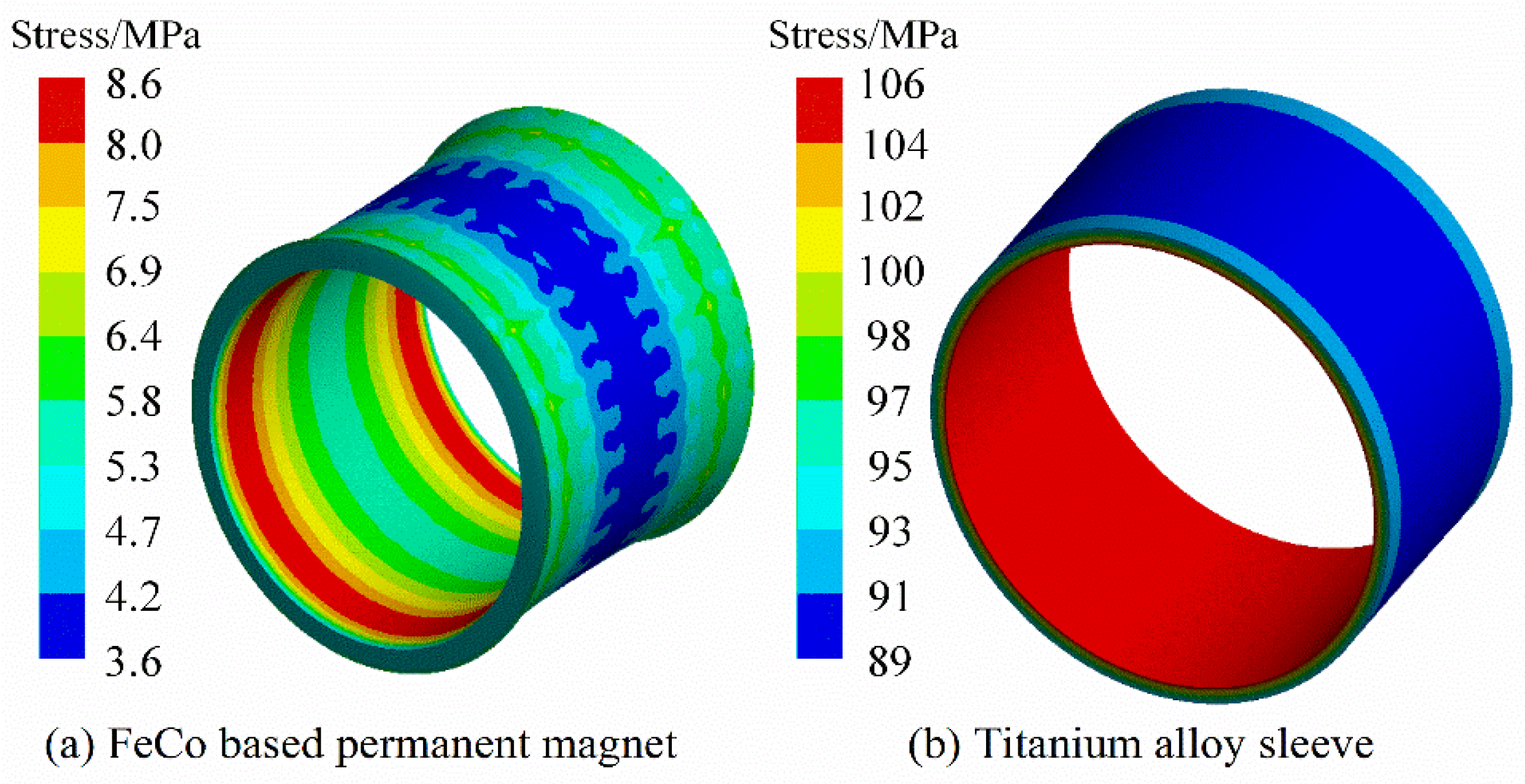
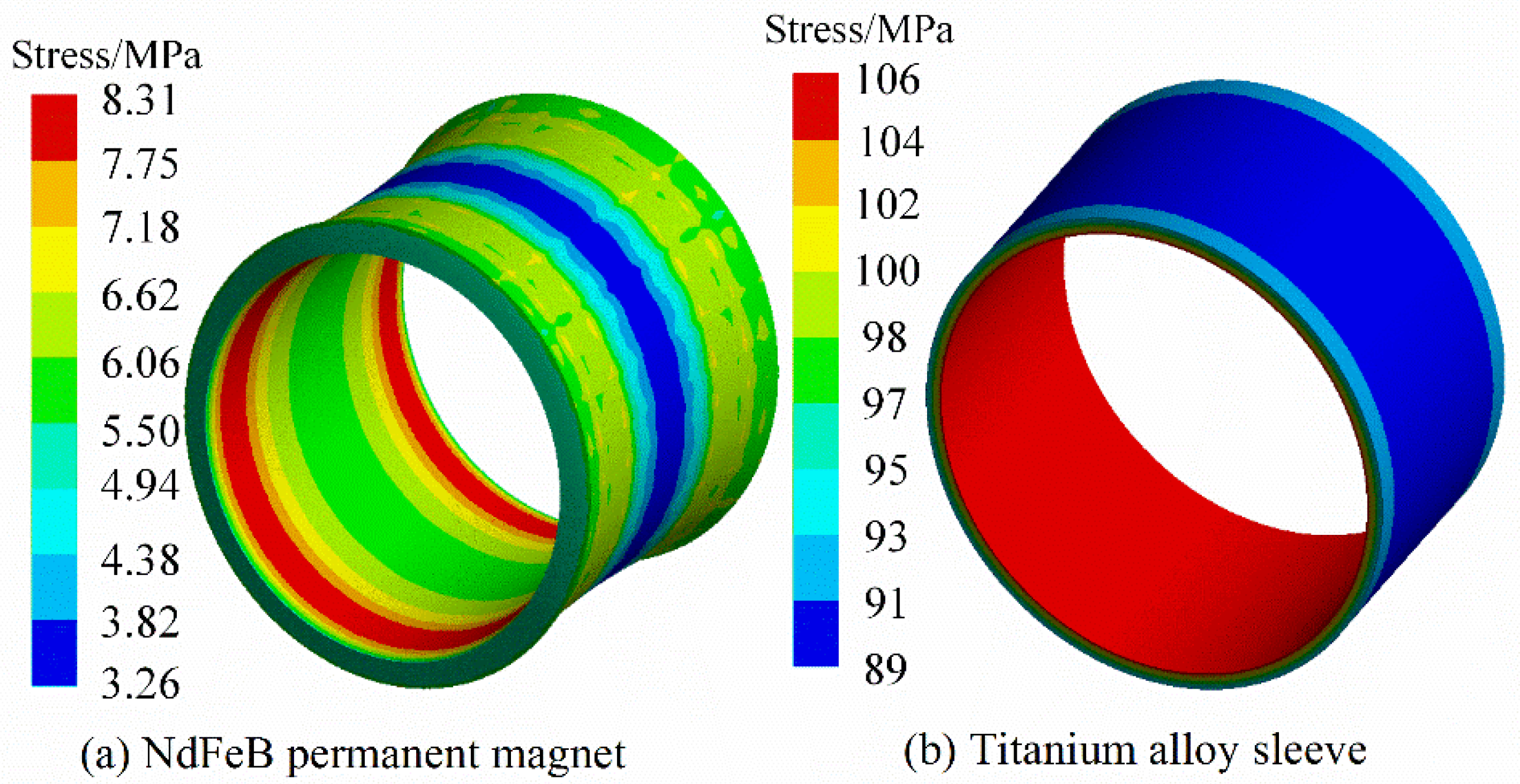
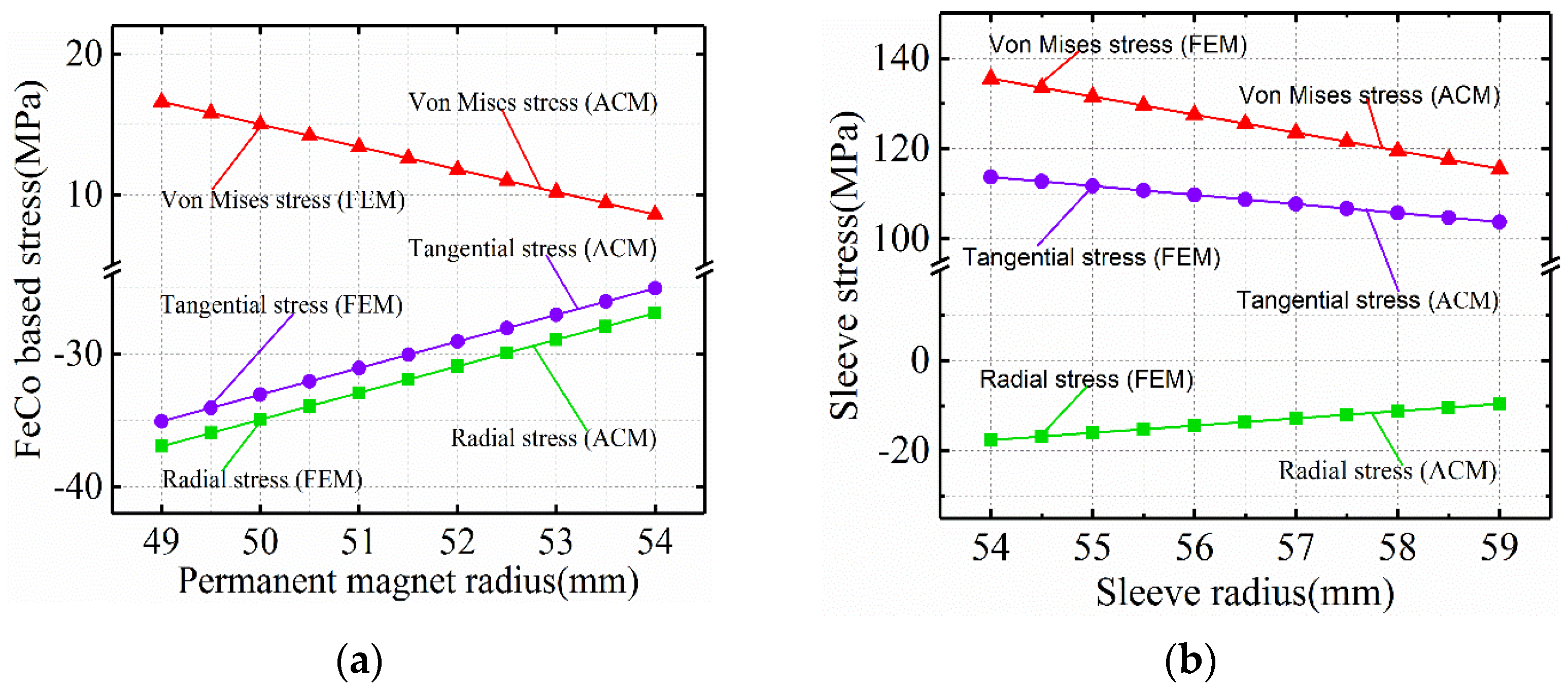
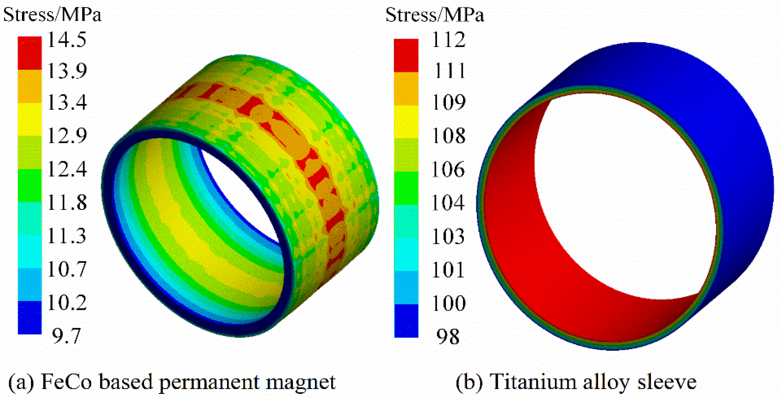
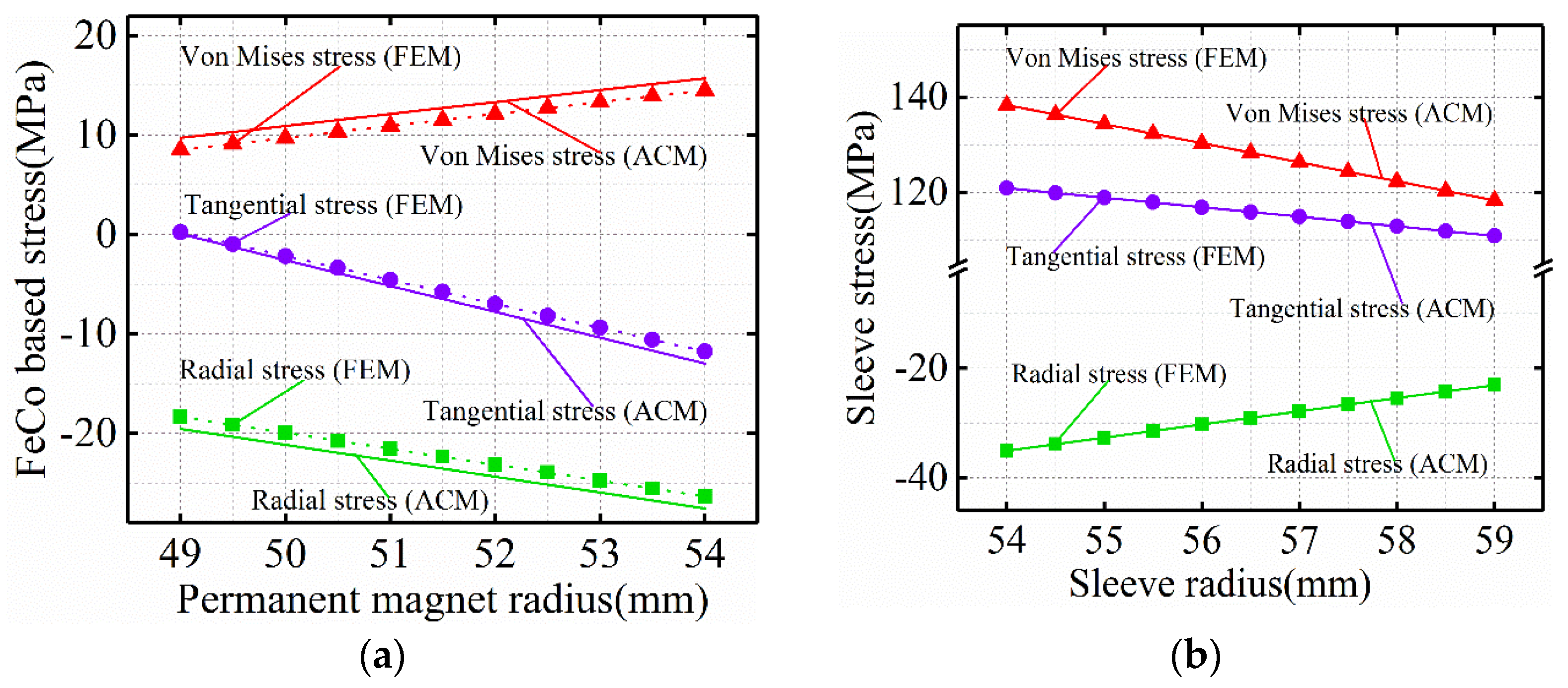
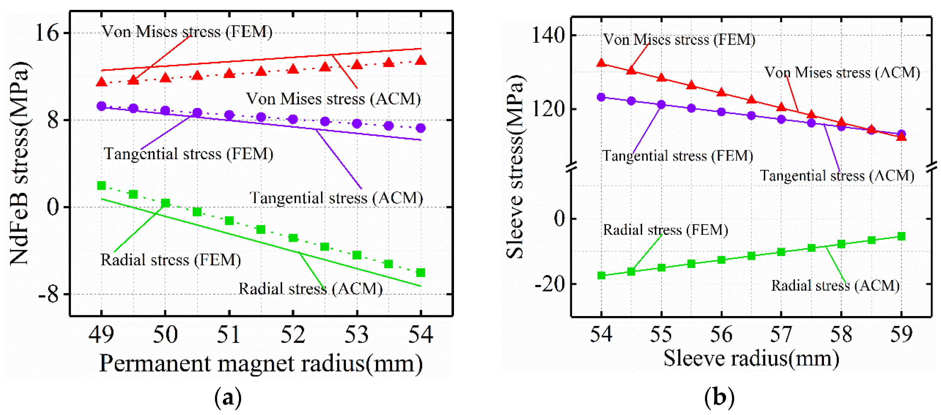
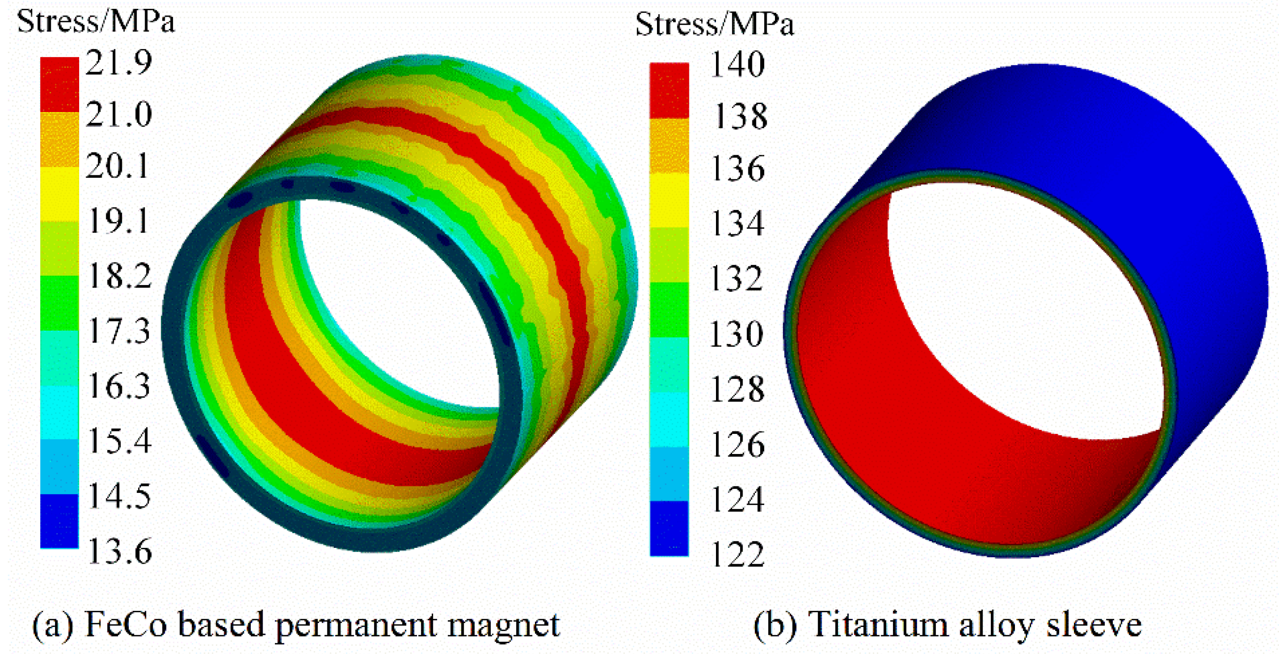
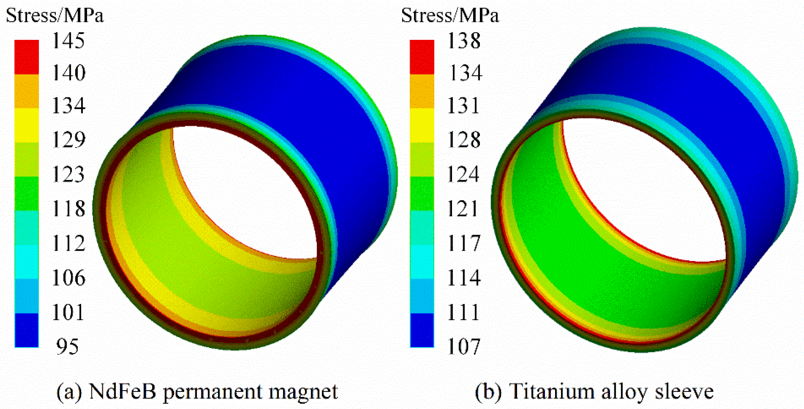
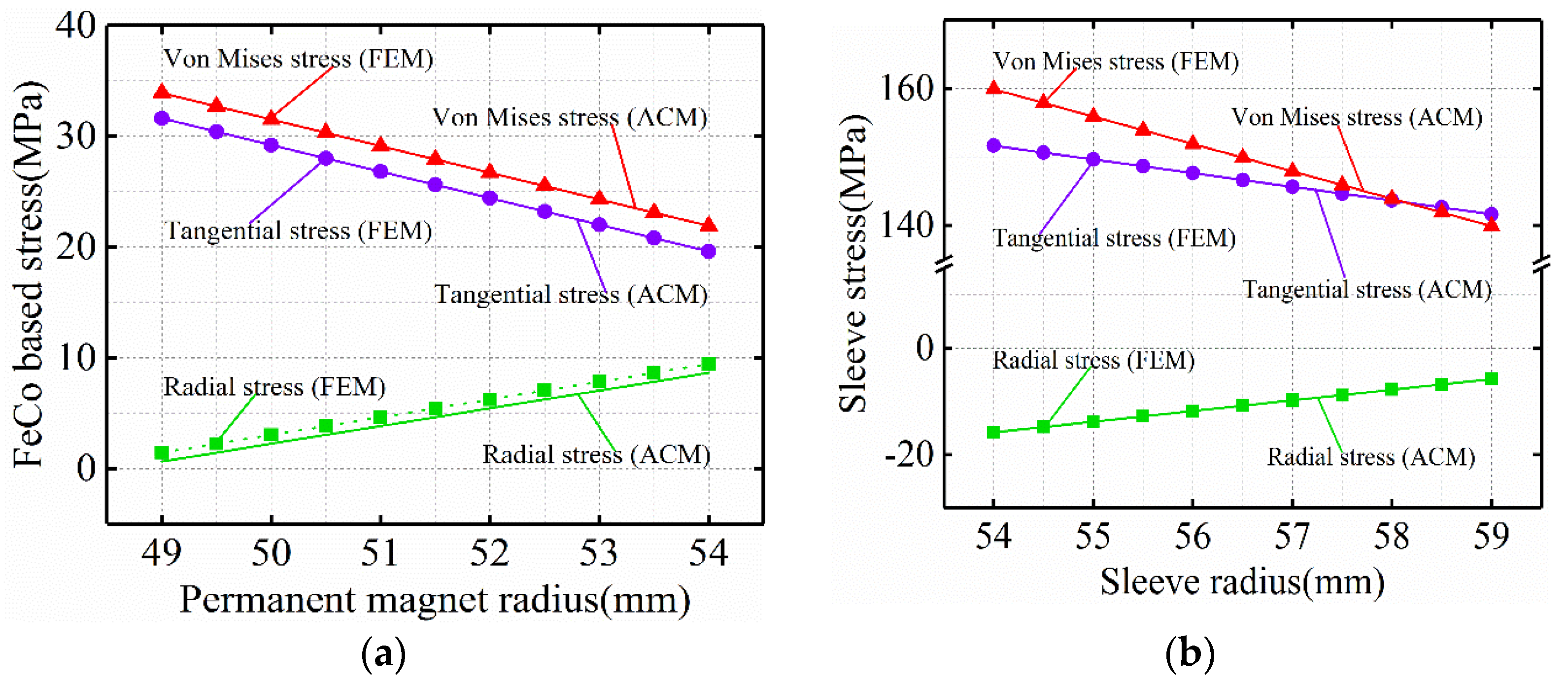
Under the steady condition (22 °C, 0 rpm/min), Figure 3 and Figure 4 are the Von-Mises stress nephograms of the sheath and the PM calculated based on the 3D finite element simulation method. The magnitude of the stress on the PM is shown in Figure 5 and Figure 6. The results of the finite element and analytical calculation are compared and analyzed, and it can be seen that the analytical method is consistent with the finite element simulation calculation results. The Von-Mises stress of the titanium alloy sleeve calculated by the analytical method is 118.8~137.5 MPa, and the Von-Mises stress of the titanium alloy sleeve calculated based on the finite element simulation is 117.2~135.3 MPa. The corresponding NdFeB permanent magnet sleeve is 108.6~127.8 MPa by finite element analysis and 107.4~125.5 MPa by analytical calculation. The Von-Mises stress on the inner surface of the titanium alloy sleeve is the largest, that is, the inner surface of the titanium alloy sleeve is easily damaged. As the radius of the titanium alloy sleeve increases, the equivalent Von-Mises stress of the titanium alloy sleeve decreases. In FeCo-based PM, both radial stress and tangential stress are expressed as compressive stress. FeCo-based PM can withstand high compressive stress.

Figure 3.
Von-Mises stress distribution of FeCo-based PM and sleeve under steady condition.
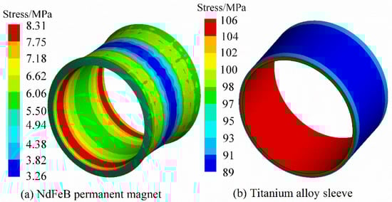
Figure 4.
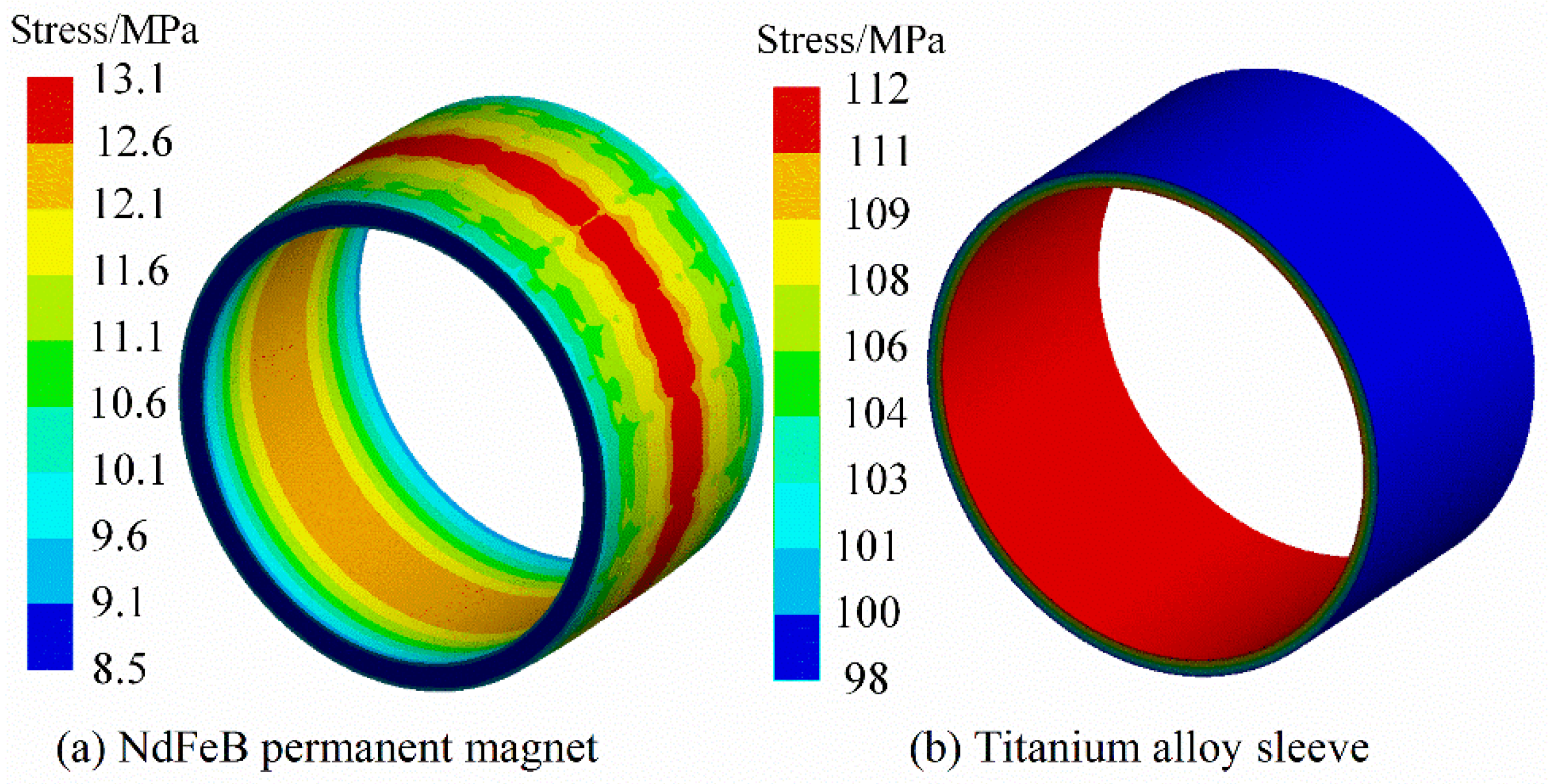
Von-Mises stress distribution of NdFeB PM and sleeve under steady condition.
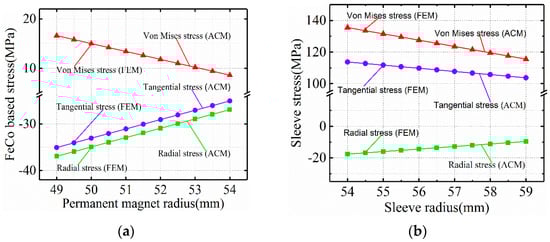
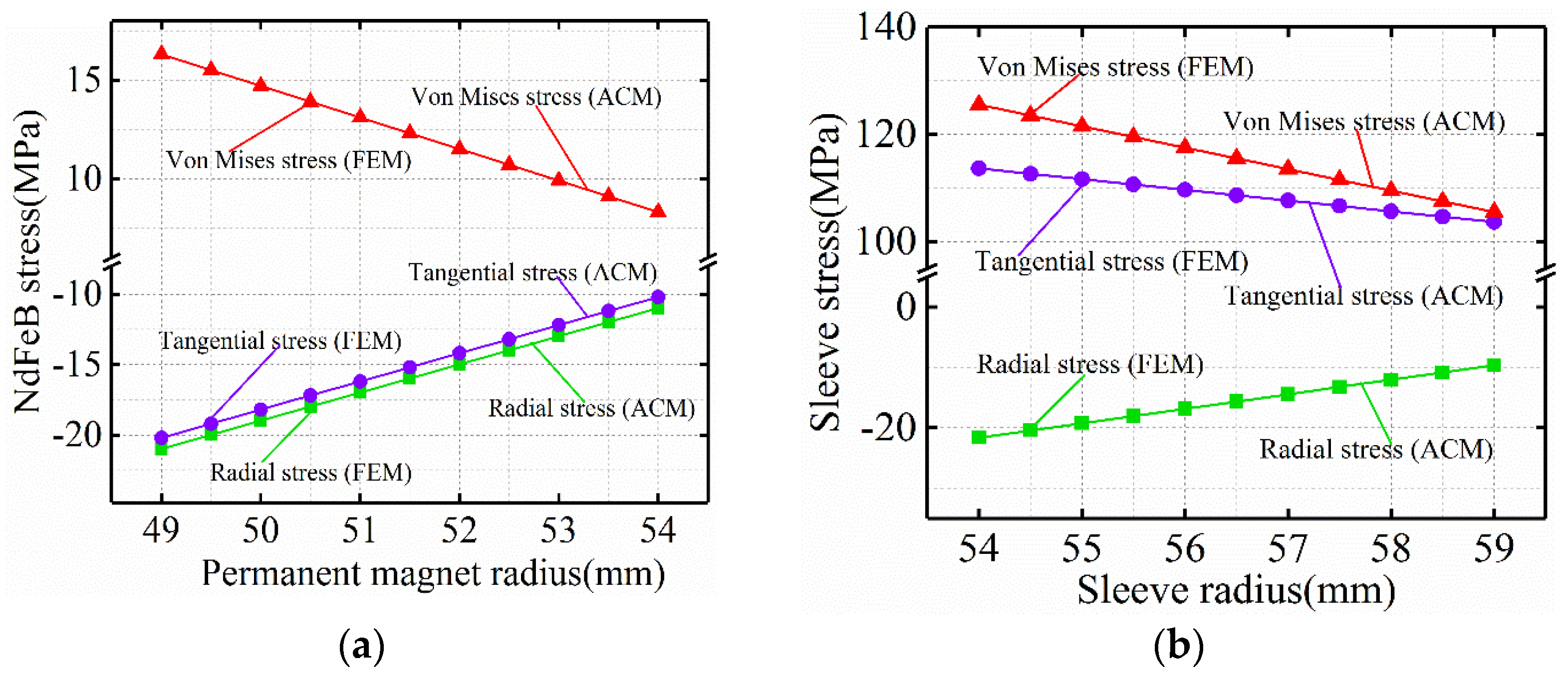
Figure 5.
Stress distribution of (a) FeCo-based PM and (b) sleeve under steady condition.
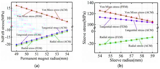
Figure 6.
Stress distribution of (a) NdFeB-PM and (b) sleeve under steady condition.
Under steady conditions, the titanium alloy sleeve and FeCo-based PM will not be damaged due to interference fit. For NdFeB PM, in other words, compared with FeCo-based PM, the Von-Mises stress of NdFeB PM is smaller than FeCo-based PM under steady condition.
3.3. Stress Analysis of Cold Rotating Condition
Under cold rotating condition (22 °C, 18,000 rpm/min), Figure 7 and Figure 8 are Von-Mises stress nephograms of titanium alloy sleeve and PM based on 3D FEM simulation calculation. The Von-Mises stress at the inner surface of titanium alloy sleeve is the highest, which is 112.29 MPa. With the increase of radius of titanium alloy sleeve, the Von-Mises stress of titanium alloy sleeve decreases. The stress values of titanium alloy sleeve and PM calculated by finite element simulation and analysis are shown in Figure 9 and Figure 10. By comparing and analyzing the finite element and analytical calculation results, it can be seen that the analytical calculation basically agrees with the calculated stress values by FEM. The radial stress of titanium alloy sleeve is still compressive stress, and the sleeve and PM are still interference fit. The Von-Mises stress of sleeve calculated by finite element simulation is 118.45~137.86 MPa. The Von-Mises stress calculated by analytical method is 119.67~139.52 MPa. The corresponding NdFeB permanent magnet sleeve is 112.63~132.75 MPa by finite element analysis and 113.96~134.24 MPa by analytical calculation. Compared with the Von-Mises stress under steady condition, the maximum Von-Mises of the titanium alloy sleeve increases slightly under cold rotating condition. The increase of Von-Mises stress of the titanium alloy sleeve is mainly caused by centrifugal force caused by high-speed rotation.
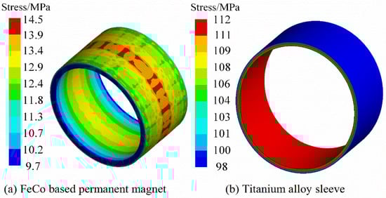
Figure 7.
Von-Mises stress distribution of FeCo-based PM and sleeve under cold rotating condition.

Figure 8.
Von-Mises stress distribution of NdFeB PM and sleeve under cold rotating condition.
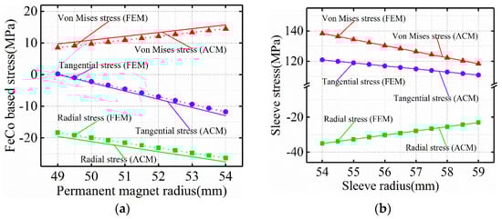
Figure 9.
Stress distribution of (a) FeCo-based PM and (b) sleeve under cold rotating condition.
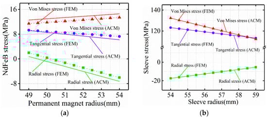
Figure 10.
Stress distribution of (a) NdFeB-PM and (b) sleeve under cold rotating condition.
Under the cold rotating condition, the radial stress of the FeCo-based PM presented as the compressive stress and the tangential stress as the tensile stress, and compared with that under the steady condition. The radial stress and the tangential stress of the FeCo-based PM all showed an increasing trend, that is, the compressive stress of the FeCo-based PM decreased, and after the rotation of the high-speed permanent magnetic rotor, the overfilling between the sleeve of titanium alloy and the FeCo-based PM decreased, which caused the contact pressure to decrease, leading to the reduction of the compressive stress of the FeCo-based PM. Corresponding to it, the NdFeB PM radial stress was similarly presented as compressive stress and the tangential stress as tensile stress.
3.4. Stress Analysis of Hot Rotating Condition
Under the hot rotating condition (120 °C), Figure 11 and Figure 12 are the Von-Mises stress nephograms of titanium alloy sleeve and PM calculated based on 3D FEM. The stress magnitude of titanium alloy sleeve and PM calculated by FEM and ACM is shown in Figure 13 and Figure 14. Through comparative analysis of finite element and analytical calculation results, it can be seen that the calculated stress magnitude of the two is basically consistent. The Von-Mises stress of titanium alloy sleeve calculated by FEM is 139.58~159.32 MPa, and the Von-Mises stress of titanium alloy sleeve calculated by ACM is 140.07~160.06 MPa. The corresponding NdFeB permanent magnet sleeve is 138.74~158.65 MPa by FEM analysis and 139.28~159.47 MPa by ACM. Compared with the calculation of cold rotating condition, the Von-Mises stress of titanium alloy sleeve under hot rotating condition increases.

Figure 11.
Von-Mises stress distribution of FeCo-based PM and sleeve under hot rotating condition.

Figure 12.
Von-Mises stress distribution of NdFeB PM and sleeve under hot rotating condition.
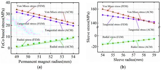
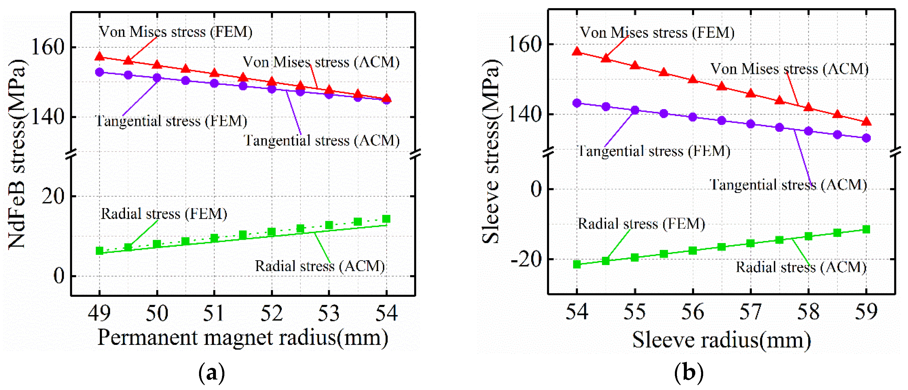
Figure 13.
Stress distribution of (a) FeCo-based PM and (b) sleeve under hot rotating condition.
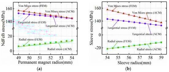
Figure 14.
Stress distribution of (a) NdFeB-PM and (b) sleeve under hot rotating condition.
Under hot rotating condition, because the TEC of carbon steel rotating shaft is greater than that of titanium alloy sleeve and PM TEC, the displacement of the outer surface of carbon steel rotating shaft caused by temperature is greater than that of PM inner surface. At the same time, the displacement of the inner surface of titanium alloy sleeve caused by temperature is less than that of FeCo-based PM outer surface. It is precisely because of the different surface displacement caused by temperature that the contact pressure between the surface of titanium alloy sleeve and PM surface increases. This leads to an increase in Von-Mises stress in the sleeve.
Under hot rotating condition, the tangential stress at the inner surface of FeCo-based PM is tensile stress. FeCo-based PM is compressive but not tensile, and the ability of tensile stress is limited. Tensile stress is easy to cause damage to FeCo-based PM. The tangential stress of FeCo-based PM calculated by finite element simulation is 19.81~32.47 MPa. The tangential stress calculated by analytical method is 20.09~33.62 MPa. Due to the expansion of rotor shaft and PM caused by temperature, the contact force between the inner diameter of PM and the outer surface of rotor shaft increases, resulting in tensile stress on the inner surface of FeCo-based PM. Since TEC of FeCo-based PM is much larger than NdFeB PM, the influence of rotor system operating temperature on NdFeB PM stress is much larger than that on FeCo-based PM stress.
4. Analysis of Influencing Factors of Rotor Stress
4.1. Influence of External Condition Parameters of Rotor
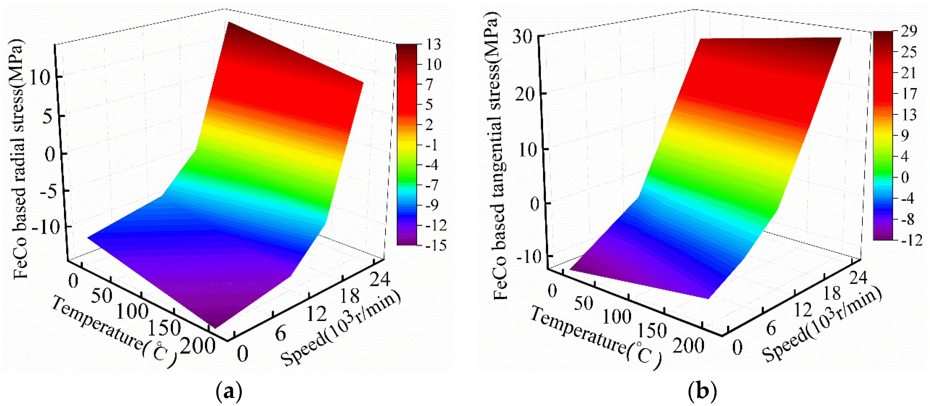
The stress distribution of high-speed permanent magnet motor rotor is very important. The stress distribution of motor rotor is affected by external conditions, motor temperature rise, rotor speed, and other factors. Figure 15 shows the 3D diagram of FeCo-based PM radial stress and tangential stress varying with temperature and speed, and Figure 16 shows the 3D diagram of NdFeB PM tangential stress and radial stress varying with temperature and speed.

Figure 15.
Influence of temperature and speed on FeCo-based PM stress. (a)FeCo based radial stress; (b) FeCo based tangential stress.
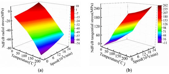
Figure 16.
Influence of temperature and speed on NdFeB-PM stress. (a) NdFeB based radial stress; (b) NdFeB based tangential stress.
As can be seen from Figure 15 and Figure 16, the rotating speed will cause the titanium alloy sleeve and PM to produce corresponding centrifugal force, and the temperature will cause the titanium alloy sleeve and PM to produce corresponding expansion displacement. This will reduce the pre-pressure of the titanium alloy sleeve on PM, and the PM tangential stress gradually increases with the increase of temperature and rotating speed. The minimum tangential stress of PM appears when the temperature and rotating speed are the lowest, which is manifested as compressive stress. When the motor rotating speed and temperature reach the highest, PM tangential stress also reaches the maximum value, which is manifested as tensile stress. Due to the pre-pressure of titanium alloy sleeve on PM, the radial stress of PM is shown as compressive stress (negative number) at steady condition. With the increase of rotor speed, the force of titanium alloy sleeve on PM due to centrifugal force begins to decrease, resulting in the radial stress of FeCo-based PM gradually approaching from negative value to positive value.
4.2. Influence of Rotor Structural Parameters
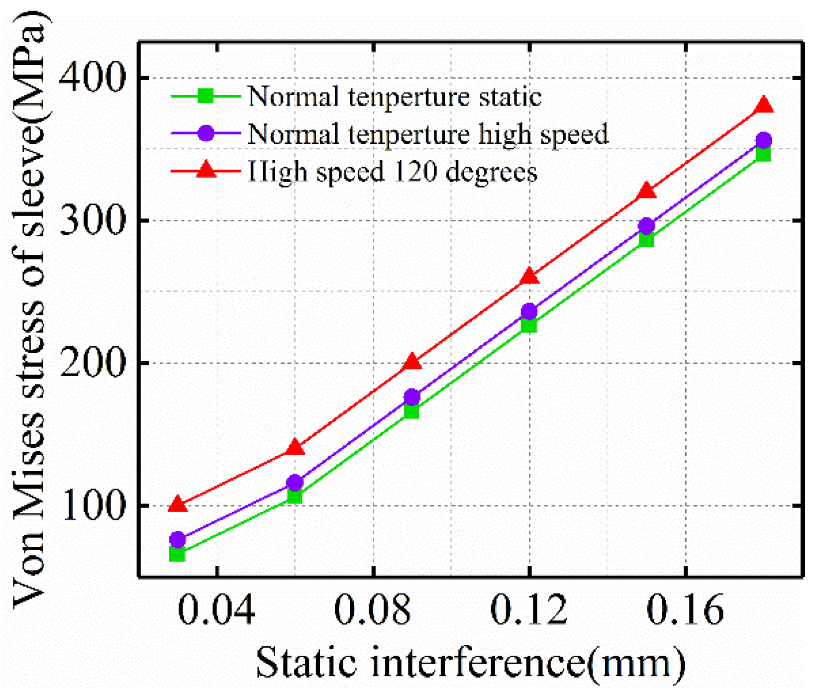
The stress distribution of the rotor is also affected by the structural parameters of the rotor, such as interference, polar arc coefficient, and sleeve thickness. Figure 17 shows the influence of static interference on the Von-Mises stress of titanium alloy sleeve under three working conditions. The Von-Mises stress of titanium alloy sleeve is the largest under hot operation.
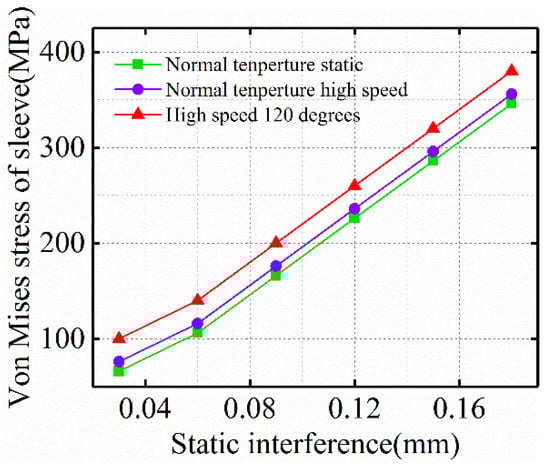
Figure 17.
Influence of static interference on sleeve stress.
The PM rotor of high-speed motor generally adopts ring PM (pole arc coefficient is equal to 1) and block PM (pole arc coefficient is less than 1). The disadvantage of ring PM is that the cost is relatively high, and there is a gap between block permanent magnets, which is easy to increase the Von-Mises stress of titanium alloy sleeve. In order to avoid this situation, the gap is usually filled with non-magnetic materials. The Von-Mises stress of titanium alloy sleeve under hot high-speed condition calculated based on finite element simulation method is shown in Table 3. Compared with the ring PM structure, the Von-Mises stress of titanium alloy sleeve has little change.
Table 3.
Von-Mises stress of sleeve under different polar arc coefficient.
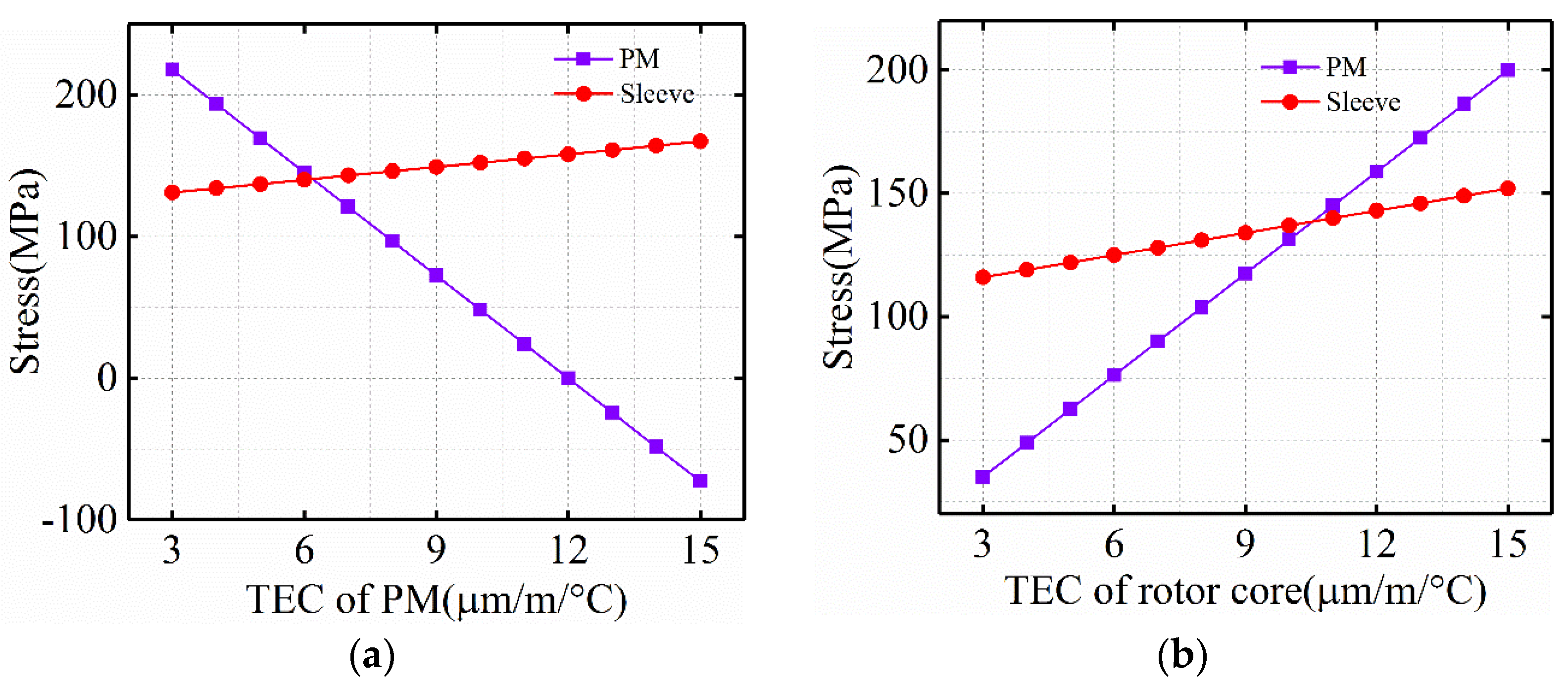
Under hot rotating conditions, the thermal expansion coefficient (TEC) of PM and rotor core have a great impact on the rotor stress. Figure 18a shows the impact of the TEC of PM on the rotor stress, and Figure 18b shows the impact of the TEC of rotor core on the rotor stress. With the increase of the TEC of rotor core, the stress of PM and sheath increases significantly. Obviously, when using PM materials with large TEC, PM will produce large temperature displacement at a high temperature. However, due to the interference fit between the sleeve and PM, PM stress can be effectively reduced. On the other hand, when TEC large rotor core is adopted, the rotor core will produce large temperature displacement at high temperature. Due to the bonding of PM and rotor core, PM will produce large tangential deformation, resulting in large PM stress. Therefore, a large PM TEC or a small rotor core TEC can greatly improve the reliability of the rotor at high temperature.
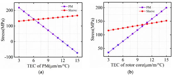
Figure 18.
Influence of TEC on sleeve stress. (a) TEC of PM; (b) TEC of rotor core.
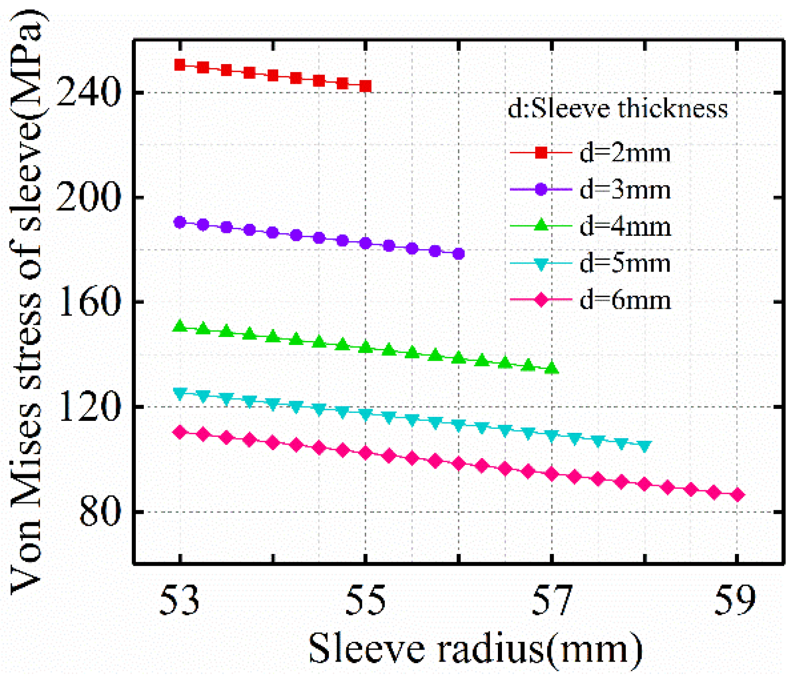
Figure 19 shows the magnitude of Von-Mises stress in the sleeve under different thickness of titanium alloy sleeve. The premise is to keep the compressive stress between the sleeve and FeCo-based PM unchanged. With the increase of sleeve thickness, the Von-Mises stress in the sleeve decreases, and the decreasing trend of Von-Mises stress in the sleeve gradually decreases with the increase of sleeve thickness.
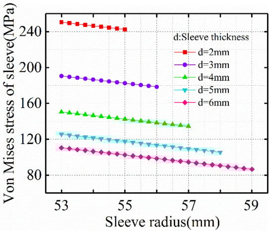
Figure 19.
Influence of sleeve thickness on sleeve Von-Mises stress.
5. Motor Testing and Analysis
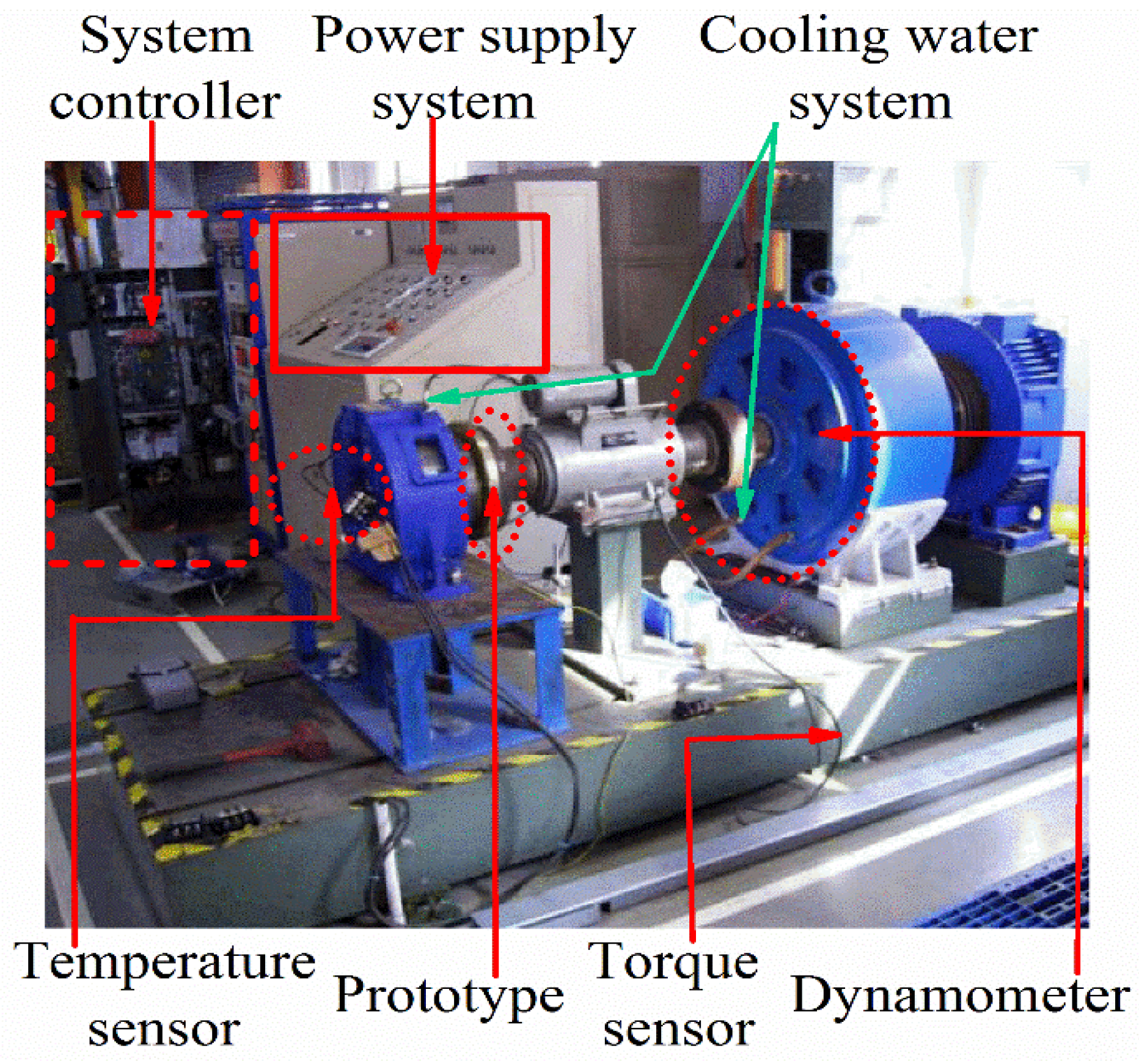
According to the above analysis, a 100 kW and 18,000 rpm/min FeCo-based PM high-speed motor was manufactured. The experimental platform is shown in Figure 20. The motor is 2 poles and 24 slots. The stator winding is three-phase, star connected, double-layer, distributed short pitch winding (pitch y = 10 slots), the outer diameter of the stator is 286 mm, the surface speed of the rotor is 111.2 m/s, and a FeCo-based PM material with a thickness of 7 mm is used. The structure of the PM is a ring. The titanium alloy sleeve with a thickness of 5 mm is wrapped on the surface of the PM material to ensure the high-speed and reliable operation of the rotor. Its main parameters are shown in Table 4. In order to test the performance of the prototype, in the experimental test, four PT100 resistance temperature sensors are placed in the stator winding, and two PT100 resistance temperature sensors are placed near the air gap of the stator to record the temperature of the stator winding and air gap. We used the power analyzer to measure the power and voltage parameters such as current and torque.
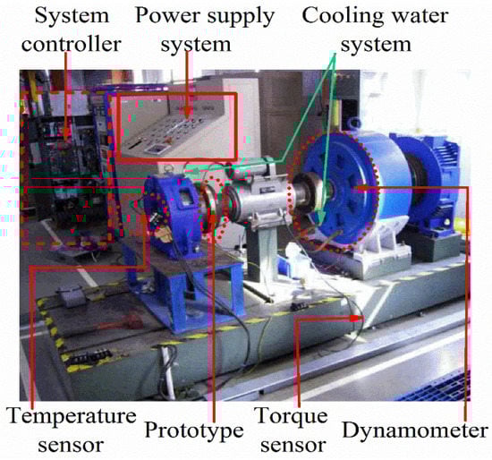
Figure 20.
Prototype experimental platform.
Table 4.
Main parameters of HSPMM.
5.1. Electromagnetic and Temperature Characteristic Test
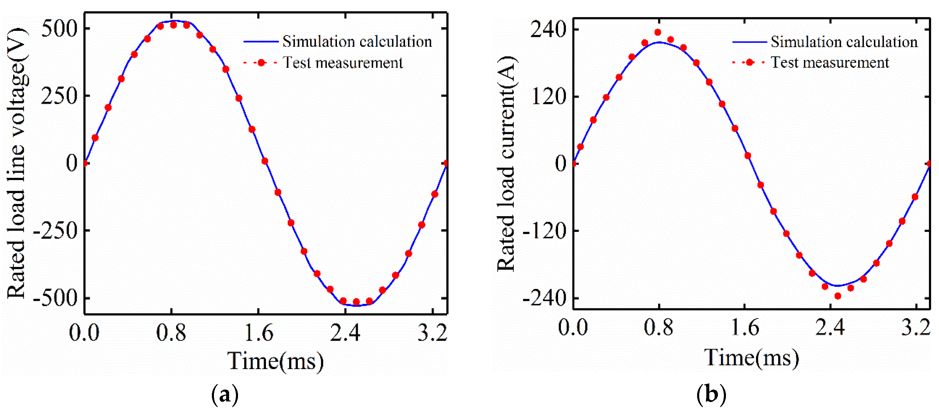
In the rated load experiment, the electromagnetic and thermal characteristics of the prototype were tested. The voltage curve measured and simulated under rated load operation is shown in Figure 21a. The measured value of root mean square (RMS) of the line voltage under rated load is 518.2 V, which is smaller than the simulated value of 529.3 V. The main reason is that the temperature of the PM during measurement and simulation calculation is different. The current curve measured and simulated under rated load operation is shown in Figure 21b. The temperature distribution in the stator winding is measured by PT100 resistance temperature sensor. In the test, the temperature rises rapidly at the beginning, and becomes very stable after 2.5 h of test.
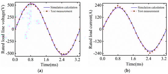
Figure 21.
Simulation calculation and measured results under rated load operation, (a) Line voltage, (b) Current.
Table 5 summarizes the key performance of the prototype and the winding temperature after stabilization. The average temperature measured by the four temperature sensors of the stator winding is 102.8 °C, and the temperature measured by the temperature sensor near the air gap on the stator side is 98.3 °C. The output power of the prototype is obtained by the platform power analyzer. The measured total power loss is 5.4 kW and the efficiency is 94.87%, indicating the rationality of the electromagnetic design of FeCo-based PM high-speed motor.
Table 5.
Comparison between numerical calculation and experimental measurements.
5.2. Times Rated Speed Test
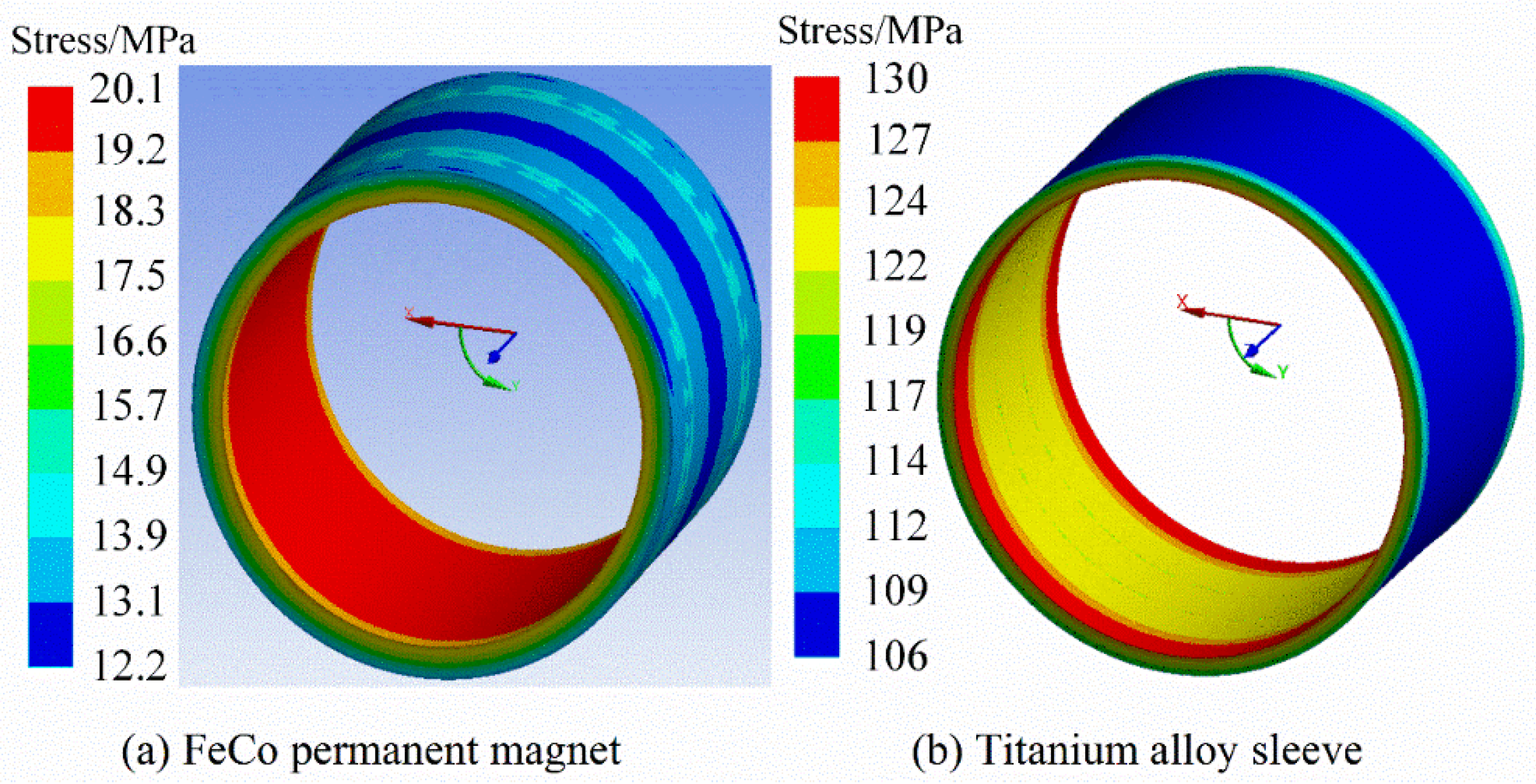
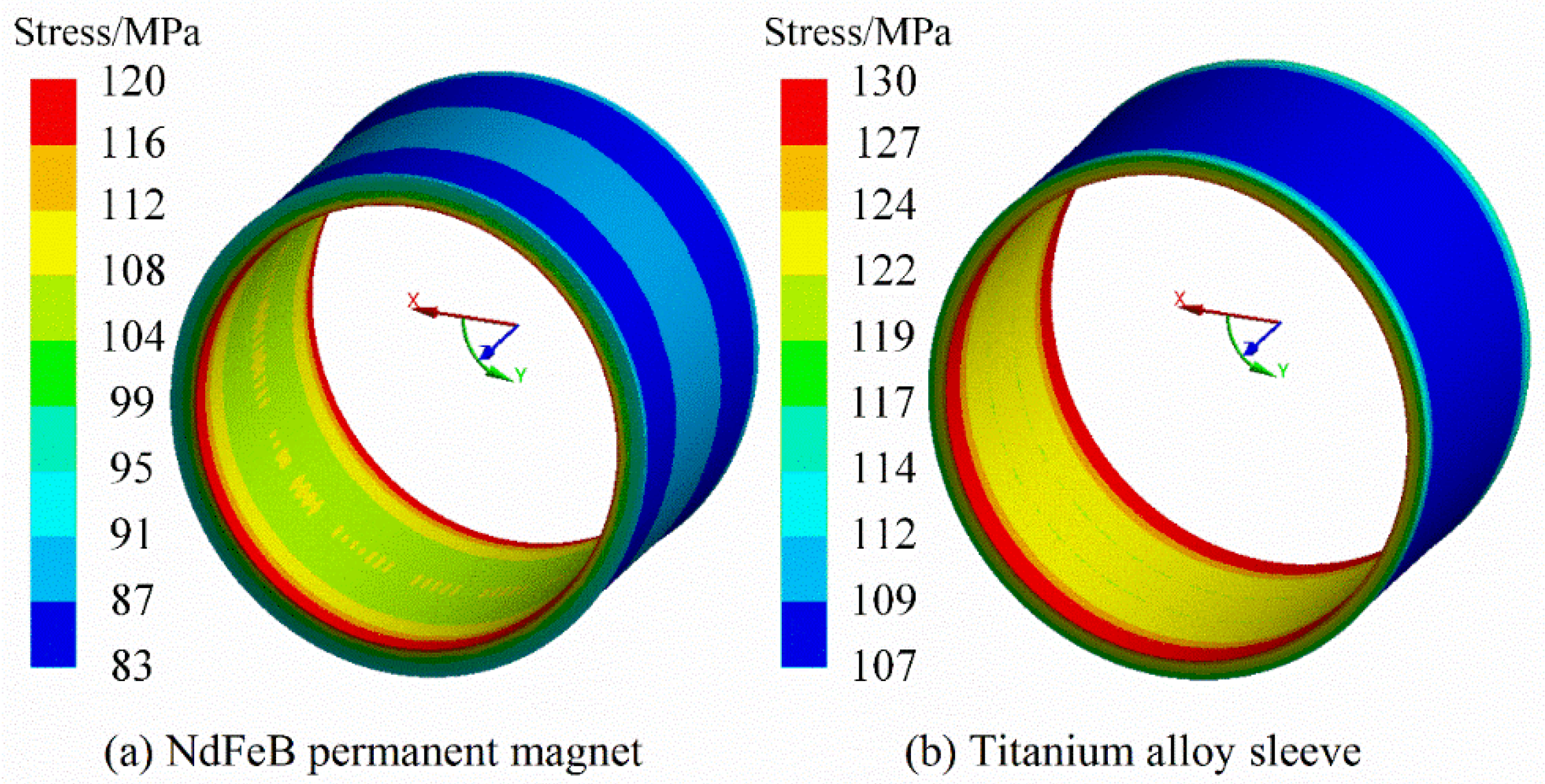
In the thermal high-speed rotor stress analysis in the previous Section 3.4, because it is estimated that the rotor temperature is constant, there will be a large error 1 compared with the actual operation of the rotor. Therefore, the rotor stress should be recalculated through the temperature stress coupling model at 1.2 times the rated speed to obtain accurate calculation results. In this analysis, the rotor temperature is determined by experimental test, and the actual temperature of the air gap near the stator side is 98.3 °C. Figure 22 and Figure 23 show the rotor stress distribution obtained through coupling analysis. The maximum FeCo-based PM stress is 20.1 MPa, the maximum NdFeB PM stress is 120 MPa, and the maximum sleeve stress is 130 MPa. It is very obvious that the stress of NdFeB PM has greatly exceeded its maximum tensile strength of 80 MPa, while FeCo-based PM and titanium alloy sleeve meet the tensile strength of the material and retain a certain safety margin.
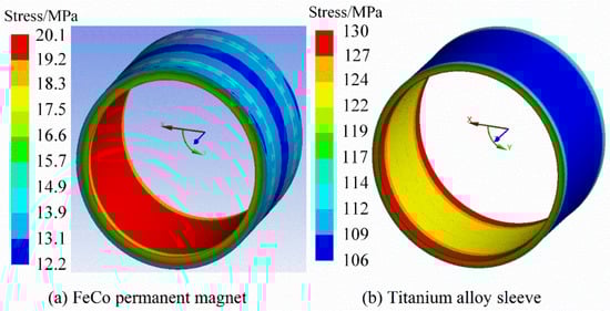
Figure 22.
Rotor stress by coupled temperature-stress model. (a) FeCo-based PM stress, (b) Sleeve.

Figure 23.
Rotor stress by coupled temperature-stress model. (a) NdFeB PM stress, (b) Sleeve.
Before measuring the no-load back electromotive force, first test the mechanical strength of the rotor at 1.2 times the rated speed. The rotor can run safely at 1.2 times the rated speed for several hours, and then carefully check the rotor surface and permanent magnet without any damage. At the same time, in order to verify the rotor stress, continuous test is also very important. In order to test the continuous working stability in practice, HSPMM has operated continuously at the rated speed for one week, and the rotor runs well without any abnormality, indicating that the rotor is safe and reliable at high-speed.
6. Conclusions
In this paper, the rotor strength of HSPMM is studied in detail. Because the tensile strength of FeCo-based PM is 70 MPa (the tensile strength of NdFeB PM is 80 MPa), it is still difficult to resist the huge centrifugal force caused by high-speed rotation. Therefore, the interference fit between titanium alloy sleeve and PM is required to generate pre-pressure to offset the centrifugal force caused by high-speed rotation and reduce the tensile stress of permanent magnet during hot high-speed operation. Finally, the prototype is tested, and the correctness of the theoretical analysis is verified and summarized as follows:
- (1)
- In this paper, the structural model of FeCo-based ring PM rotor is proposed. Based on the thick wall cylinder theory, the analytical expression of the stress between the sleeve and the PM is deduced. The influence of speed and temperature on the strength of the high-speed PM rotor is considered in the analytical calculation, and the accuracy of the analytical calculation is verified by the finite element method. The calculation comparison results show that it is necessary to consider the influence of temperature in the strength calculation.
- (2)
- Due to the large coefficient of thermal expansion of FeCo-based PM, the effect of rotor temperature on FeCo-based PM stress is much less than that on NdFeB PM stress.
- (3)
- The TEC of the rotating shaft affects the stress distribution when the rotor rotates at high-speed in hot state. The TEC of the rotating shaft is large. When the rotor rotates at high-speed in hot state, the stress on the sleeve and PM is the largest, and the tangential stress of the PM increases significantly, even showing tensile stress.
- (4)
- Using PM materials with large TEC or rotor core with small TEC can greatly reduce the stress of PM.
Author Contributions
Conceptualization, B.G.; software, P.H.; formal analysis, P.H. and B.P.; data curation, P.H.; writing—original draft preparation, P.H.; writing—review and editing, P.H. and B.G.; supervision, B.G.; funding acquisition, D.T. and Y.W. All authors have read and agreed to the published version of the manuscript.
Funding
This research was funded by the China National Defense Basic Research Project: JCKY2018412C006.
Institutional Review Board Statement
The study did not involve humans or animals.
Informed Consent Statement
Not applicable.
Data Availability Statement
The study did not report any data.
Conflicts of Interest
The authors declare no conflict of interest.
References
- Hu, Y.; Li, L.; Guo, W.; Wang, S. Study on the Rotor Strength of High-Speed Permanent Magnet Motor Considering the Influence of Assembly Pressing Force. Symmetry 2021, 13, 2161. [Google Scholar] [CrossRef]
- Zhao, J.; Lu, Q.; Yang, D. Experimental and Numerical Analysis of Rotor–Rotor Interaction Characteristics inside a Multistage Transonic Axial Compressor. Energies 2022, 15, 2627. [Google Scholar] [CrossRef]
- Du, G.; Xu, W.; Zhu, J.; Huang, N. Rotor Stress Analysis for High-Speed Permanent Magnet Machines Considering Assembly Gap and Temperature Gradient. IEEE Trans. Energy Convers. 2019, 34, 2276–2285. [Google Scholar] [CrossRef]
- Wu, S.; Huang, X.; He, L.; Cui, S.; Zhao, W. Mechanical Strength Analysis of Pulsed Alternator Air-Core Rotor. IEEE Trans. Plasma Sci. 2019, 47, 2387–2392. [Google Scholar] [CrossRef]
- Zhang, F.; Ye, H.; Liu, G.; Qiu, F. Design and analysis of 100 kW high speed permanent magnet synchronous motor. In Proceedings of the IEEE Transportation Electrification Conference and Expo, Asia-Pacific, Busan, Korean, 1–4 June 2016; IEEE: Piscataway, NJ, USA, 2016. [Google Scholar]
- Karmaker, H.; Guedes-Pinto, P.; Chen, E.; Keck, J.; Ledezma, E.; Fox, K.C. High speed MW-rated induction motor drive system. In Proceedings of the IEEE International Electric Machines and Drives Conference (IEMDC), Miami, FL, USA, 21–24 May 2017; IEEE: Piscataway, NJ, USA, 2017. [Google Scholar]
- Fang, H.; Qu, R.; Li, J.; Zheng, P.; Fan, X. Rotor Design for High Speed High-Power Permanent-Magnet Synchronous Machines. IEEE Trans. Ind. Appl. 2017, 53, 3411–3419. [Google Scholar] [CrossRef]
- Jang, G.-H.; Ahn, J.-H.; Kim, B.-O.; Lee, D.-H.; Bang, J.-S.; Choi, J.-Y. Design and Characteristic Analysis of a High-Speed Permanent Magnet Synchronous Motor Considering the Mechanical Structure for High-Speed and High-Head Centrifugal Pumps. IEEE Trans. Magn. 2018, 54, 11. [Google Scholar] [CrossRef]
- Du, G.; Xu, W.; Zhu, J.; Huang, N. Effects of Design Parameters on the Multiphysics Performance of High-Speed Permanent Magnet Machines. IEEE Trans. Ind. Electron. 2020, 67, 3472–3483. [Google Scholar] [CrossRef]
- Du, G.; Huang, N. Multiphysics analysis of high-speed permanent magnet generators for waste heat application. IET Electr. Power Appl. 2020, 14, 937–942. [Google Scholar] [CrossRef]
- Du, G.; Huang, N.; Lei, G.; Zhu, J. Parameter Design for a High-Speed Permanent Magnet Machine under Multiphysics Constraints. IEEE Trans. Energy Convers. 2020, 35, 2025–2035. [Google Scholar] [CrossRef]
- Zhang, Y.; Wang, H.; Gerada, C. Rotor Eddy Current Loss and Multiphysics Fields Analysis for a High-Speed Permanent Magnet Machine. IEEE Trans. Ind. Electron. 2020, 68, 5100–5111. [Google Scholar] [CrossRef]
- Zhang, F.; Du, G.; Wang, T.; Liu, G.; Cao, W. Rotor Retaining Sleeve Design for a 1.12-MW High-Speed PM Machine. IEEE Trans. Ind. Appl. 2015, 51, 3675–3685. [Google Scholar] [CrossRef] [Green Version]
- Uzhegov, N.; Smirnov, A.; Park, C.H.; Ahn, J.H.; Heikkinen, J.; Pyrhönen, J. Design Aspects of High-Speed Electrical Machines with Active Magnetic Bearings for Compressor Applications. IEEE Trans. Ind. Electron. 2017, 64, 8427–8436. [Google Scholar] [CrossRef]
- Papini, L.; Raminosoa, T.; Gerada, D.; Gerada, C. A High-Speed Permanent-Magnet Machine for Fault-Tolerant Drivetrains. IEEE Trans. Ind. Electron. 2014, 61, 3071–3080. [Google Scholar] [CrossRef]
- Bianchi, N.; Bolognani, S.; Luise, F. Analysis and Design of a PM Brushless Motor for High-Speed Operations. IEEE Trans. Energy Convers. 2005, 20, 629–637. [Google Scholar] [CrossRef]
- Cheng, W.; Geng, H.; Feng, S.; Yu, L. Rotor Strength Analysis of High-speed Permanent Magnet Synchronous Motors. Proc. CSEE 2012, 32, 87–95. [Google Scholar]
- Korkosz, M.; Bogusz, P.; Prokop, J. Complex Performance Analysis and Comparative Study of Very High-Speed Switched Reluctance Motors. IEEE Trans. Magn. 2019, 55, 1–14. [Google Scholar] [CrossRef]
- Chen, L.L.; Zhu, C.S.; Zhong, Z.; Liu, B. Rotor strength analysis for high-speed segmented surface-mounted permanent magnet synchronous machines. IET Electr. Power Appl. 2018, 12, 979–990. [Google Scholar] [CrossRef]
- Borisavljevic, A.; Polinder, H.; Ferreira, J.A. On the Speed Limits of Permanent-Magnet Machines. IEEE Trans. Ind. Electron. 2010, 57, 220–227. [Google Scholar] [CrossRef]
- Burnand, G.; Araujo, D.M.; Perriard, Y. Very-high-speed permanent magnet motors: Mechanical rotor stresses analytical model. In Proceedings of the IEEE International Electric Machines and Drives Conference (IEMDC), Miami, FL, USA, 21–24 May 2017; IEEE: Piscataway, NJ, USA, 2017; pp. 1–7. [Google Scholar]
- Pfister, P.D.; Perriard, Y. A 200,000 rpm, 2 kW slotless permanent magnet motor. In Proceedings of the International Conference on Electrical Machines & Systems, Wuhan, China, 17–20 October 2008; IEEE: Piscataway, NJ, USA, 2008; pp. 1–6. [Google Scholar]
- Ahn, J.H.; Cheol, H.; Kim, C.W.; Choi, J.-y. Rotor Design of High-Speed Permanent Magnet Synchronous Motors Considering Rotor Magnet and Sleeve Materials. IEEE Trans. Appl. Supercond. 2017, 28, 1–4. [Google Scholar] [CrossRef]


Publisher’s Note: MDPI stays neutral with regard to jurisdictional claims in published maps and institutional affiliations. |
© 2022 by the authors. Licensee MDPI, Basel, Switzerland. This article is an open access article distributed under the terms and conditions of the Creative Commons Attribution (CC BY) license (https://creativecommons.org/licenses/by/4.0/).