Abstract
Tooth flank twist is a common phenomenon in the helical crowning modification of helical cylindrical gear, which reduces the performance of the gear. At present, the measurement of tooth flank twist is still in the stage of replacing surface with line. The development of 3-D measurement technology makes the acquisition of gear information more comprehensive and complete. By processing the 3-D point cloud data, the twist deviation on the tooth flank can be found, which is particularly important for improving the quality of the tooth flank. In this paper, a characterization method of tooth flank twist based on orthogonal polynomials was proposed, which can effectively separate the twist deviations existing on the tooth flank. The correctness of the method was verified by measurement experiments. Taking worm grinding wheel grinding to process helical crowning modification as an example, the model of various parameters of the gear and the amount of twist was established and the twist deviation in processing was predicted. This provides a new method for eliminating the twist deviation of the tooth flank.
1. Introduction
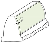
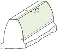
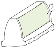
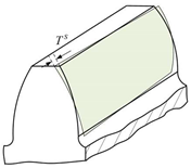
In gear topology modification, helix crowning modification is widely used because of its simple implementation method and good effect in compensating the deformation under load and the installation error [1]. However, the theoretical geometric error when processing the longitudinal modification of the gears with the hobbing, grinding and other gear processes, will lead to the tooth flank twist, as shown in Figure 1. The twist will become more and more serious with the increase of the amount of the crowning and the gear helix angle [2]. The twist of the tooth flank will cause problems such as larger backlash, larger vibration and shock, and will reduce transmission accuracy, resulting in poor gear meshing performance and increased meshing noise [3].
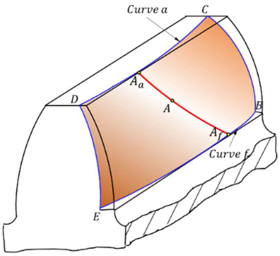
Figure 1.
Twist phenomenon on tooth flank.
At present, the research on tooth flank twist can be divided into three types. One is how to avoid tooth flank twist in the machining process, which has been studied by many scholars. Hsu R. H. proposed a shaving method for double crowning that has no natural twist in the tooth flanks on the work gear surfaces. It uses a variable pressure angle shaving cutter in a parallel gear shaving process [4]. Sohn J. proposed an improved worm gear hobbing method. This method does not require a new hobbing mechanism or hob geometry. Machining of non-twisted flanks was achieved with modified machine settings and modified hob specifications [5]. Walter Graf proposed a method for controlling tooth flank twist applied in the automotive field, which is called twist control grinding (TCG). The purpose of TCG is to either eliminate twist, to introduce a counter-twist on purpose, or to add a specific twist to counteract the deformation of gears under load [6]. A method for topological modification of gear flanks in continuous generating grinding based on contact trace evaluated genetic algorithm (CTEGA) has been proposed by Xiaoqing Tian to solve the problem of flank twist caused by lead modifications of gear flanks [7]. The second is how to measure the tooth flank twist. In the current mainstream gear measurement, the gear measurement center can measure the parameters of the gear, such as the profile deviation, the helix deviation, the twist of the transverse profile, and the twist of the flank line. No matter which parameter, the gear measurement center is used for measuring the characteristic lines. There is a possibility that the measurement of key features on the tooth flank is inaccurate. The third category is how to characterize tooth flank twist. The usual operation is to measure several lines on the tooth flank, such as two tooth profiles or two helical lines. This method of replacing the flank with lines to evaluate the quality of the gear has inherent defects. The main reason is that the amount of gear error information is insufficient, which leads to two problems: one is that it cannot reveal all the topological characteristics of the actual gear error; the other is that it may produce wrong evaluation results [8,9].
Although scholars from various countries have studied many methods to avoid tooth flank twist, these methods are not suitable for high-volume and low-cost manufacturing due to the complex tool shape or complex control process. In actual production, three-dimensional topological modification gear is more and more widely used, however, the phenomenon of tooth flank twist still exists. The characterization of twist in ISO21771 uses two tooth profiles or two helical lines, which is difficult to represent the true tooth flank twist deviation. The tooth flank of involute helical gear may be distorted whether it is grinded with a worm ground wheel or a formed grinding wheel. Each transverse profile deviation of the tooth flank is different, and the profile deviations of the left and right tooth flank of the same transverse section are also different. Using traditional tooth profiles and helical measurements to evaluate this tooth flank twist will lead to inaccurate results, and the tooth flank twist phenomenon in actual production is not easy to be found [9,10]. With the rapid development of optical non-contact measurement, the three-dimensional measurement of gears can obtain all tooth surface information. How to obtain the tooth flank twist to easily be neglected from the full information measurement data of tooth flank becomes more and more important. Therefore, it is urgent to study the characterization method of tooth flank twist based on complete tooth flank data. It can be used to solve various problems caused by tooth flank twist and can also be used to improve the machining accuracy and performance of gears [11,12].
2. Deviation Characterization of Tooth Flank
2.1. Tooth Flank Deviation under the Meshing Plane Coordinate System
According to the principle of gear meshing, any point on the tooth flank can find a corresponding point on the meshing plane. The characteristic line on the tooth flank also has a corresponding mapping relationship on the meshing plane. The mapping process involves two coordinate systems, one is the gear coordinate system, and the other is the meshing plane coordinate system [13,14].
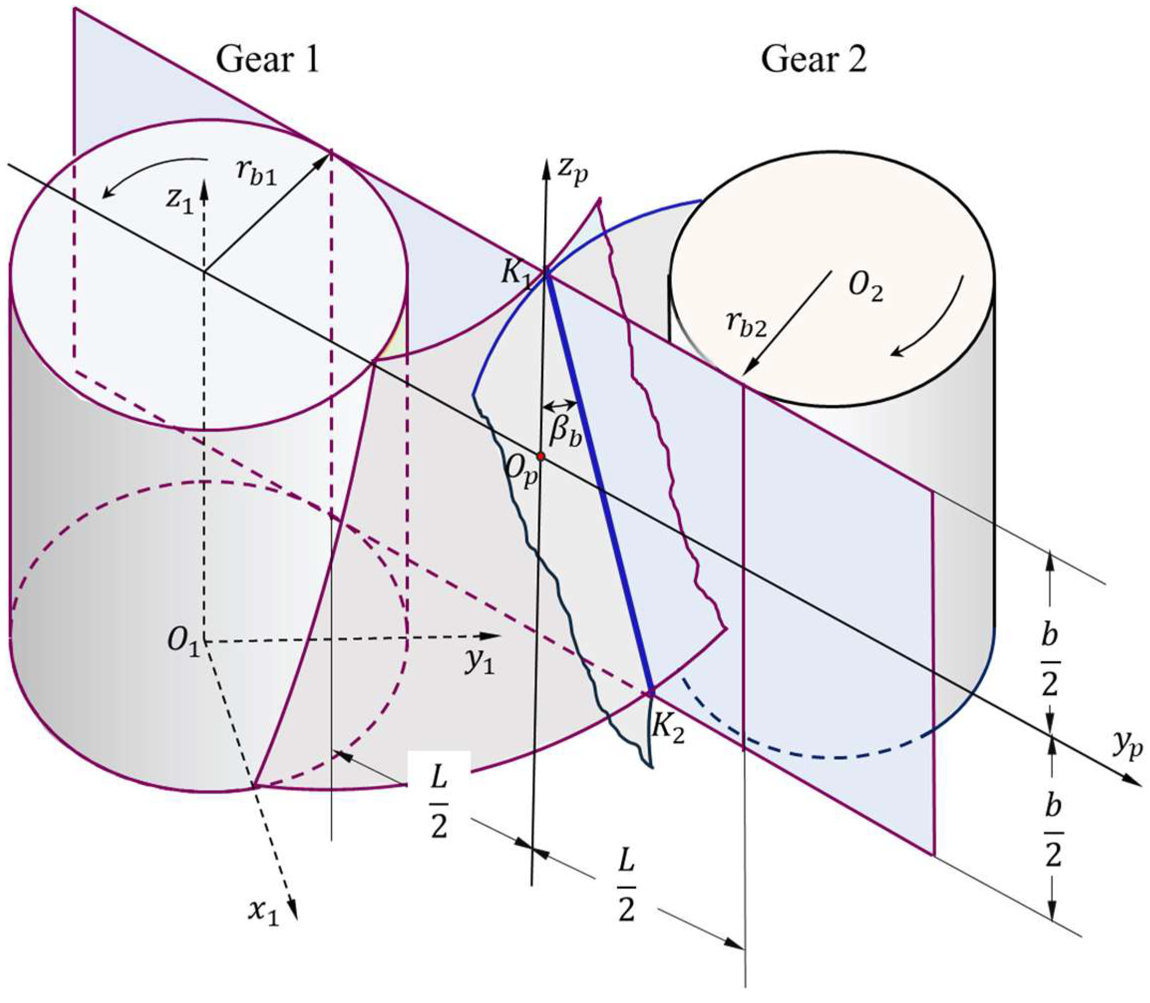
As shown in Figure 2, the axis is located at the root of the tooth of Gear 1, the axis is perpendicular to it, and the plane is perpendicular to the axis. The axis coincides with the gear axis, and the origin is located at the bottom surface of the gear. indicates the radius of the base cylinder. The tooth flank can be regarded as the curved surface formed by the spiral movement of the involute on the plane along the axis. Gear 2 is the mating gear of Gear 1.

Figure 2.
Gear coordinate system and meshing plane coordinate system.
When the gears are meshed, a coordinate system is established in the meshing area. The axis and the axis are respectively along the tooth profile rolling direction and the facewidth direction. Its origin is located in the center of the selected analysis area with the dimension in the facewidth direction and the dimension L in the rolling direction of the tooth profile. is the contact line during meshing, and its angle with the gear axis is .
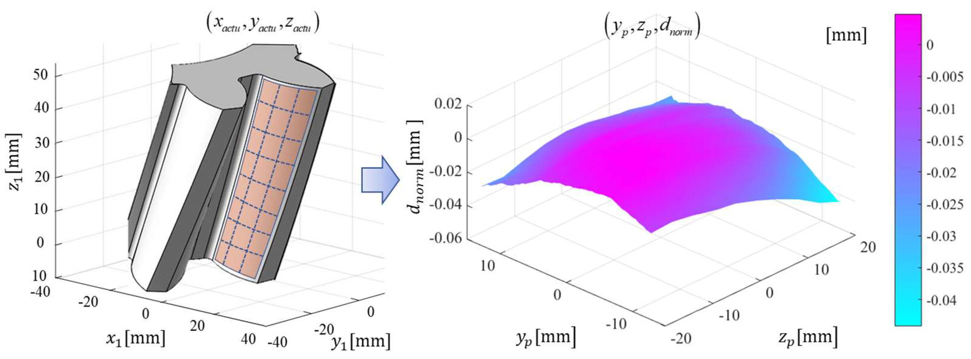
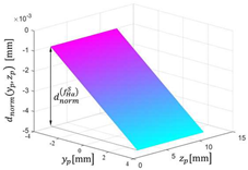
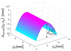
A mapping relationship is established between the gear 3-D coordinate system and the 2-D coordinate system of the meshing plane. This is a dimensionality reduction method, which facilitates and simplifies the visualization and evaluation of the 3-D deviation of the gear. Therefore, according to the actual point on the tooth flank, the normal deviation of the tooth flank at this point can be calculated. Then, the normal deviation can be transformed from the gear coordinate system to the gear meshing plane coordinate system, and the normal deviation map representing the entire tooth flank can be obtained. Figure 3 shows the actual point cloud in the gear coordinate system and its normal deviation map in the meshing plane coordinate system.
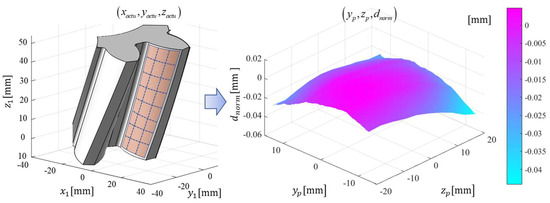
Figure 3.
Deviation map calculated 3-D point cloud of actual gear tooth flank.
2.2. 3-D Deviation Characterization of Tooth Flank Based on Legendre Polynomials
The 3-D deviation of the tooth flank can be characterized by the Legendre orthogonal polynomials after the dimensionality reduction of the 3-D deviation of the tooth flank.
2.2.1. Legendre Polynomials
Legendre polynomials are a series of polynomials obtained by solving the Legendre equation in a spherical coordinate system by separating variables. It is expressed by and has orthogonality and normalization [15,16]. The recurrence relation of is
2-D Legendre polynomials can be expressed as the product of two 1-D polynomials
and represent the order of each direction respectively, and are 1-D Legendre polynomials along the and directions, and is defined in , which still satisfies the orthogonality. The first six terms of the 2-D Legendre polynomials can be expressed as
Because the Legendre polynomials are orthogonal in the interval [−1,1] and the coefficients are independent with each other, it can effectively reduce the interference of accidental factors and simplify the calculation. The Legendre polynomials have enough accuracy to represent the geometric deviation on the theoretical tooth flank. Therefore, 2-D normalized Legendre polynomials can be used to accurately represent the tooth flank deviation in the form of superposition, so as to characterize the 3-D deviation of the gear.
2.2.2. 3-D Deviation Characterization of Tooth Flank
The normal deviation in Figure 3 is characterized by orthogonal polynomials in the meshing plane coordinate system. Further, through deviation decomposition, the normal deviation can be decomposed into various deviations on the tooth flank [12].
In the meshing plane coordinate system, represents the geometric deviation between the actual tooth flank and the involute surface with the serial number . The deviation of the tooth flank can be expressed as
where is the expansion coefficient, and are the normalized Legendre polynomials on the tooth flank along the facewidth direction and the tooth profile rolling direction, respectively. k and represent the orders of the axis and axis, respectively. The equations of and are as Equations (5) and (6).
According to the given measured tooth flank data, the tooth flank deviation can be calculated by Equation (4). The sum of the finite can approximate the geometry of as
where is the expansion coefficient of the of the normalized 2-D Legendre polynomials on tooth and is the total number of terms used to reconstruct the .
The expansion coefficient corresponds to the normal deviation on the tooth flank. In theory, the infinite expansion coefficient can completely and accurately describe the normal deviation on the tooth flank.
For any tooth , the coefficients of the Legendre polynomials can be written in matrix form, as shown in Equation (8).
The expansion coefficients in the horizontal direction in the matrix represent the deviation along axis, and the expansion coefficients in the vertical direction represent the deviation along axis.
The relationship between several characteristic deviations on the tooth flank and the 2-D Legendre polynomials is summarized in Table 1. Table 2 presents the relationship between the expansion coefficients of the 2-D Legendre polynomials and several typical deviations on the tooth flank.

Table 1.
Deviations of tooth flank and 2-D Legendre polynomials characterization.
Table 2.
Relationship between expansion coefficients and typical deviations of tooth flank.
3. Characterization of Tooth Flank Twist Based on Legendre Polynomials
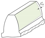
According to the definition of flank twist in ISO21771, it can be divided into twist of the transverse profile and twist of the flank line .
Twist of the transverse profile is defined as , and . is the slope modification amount of the transverse profile. If the modification amount is regarded as the tooth flank deviation, then
Twist of the flank line is defined as , and . is the slope modification amount of the helix. Similarly, if the modification amount is regarded as the tooth flank deviation, then
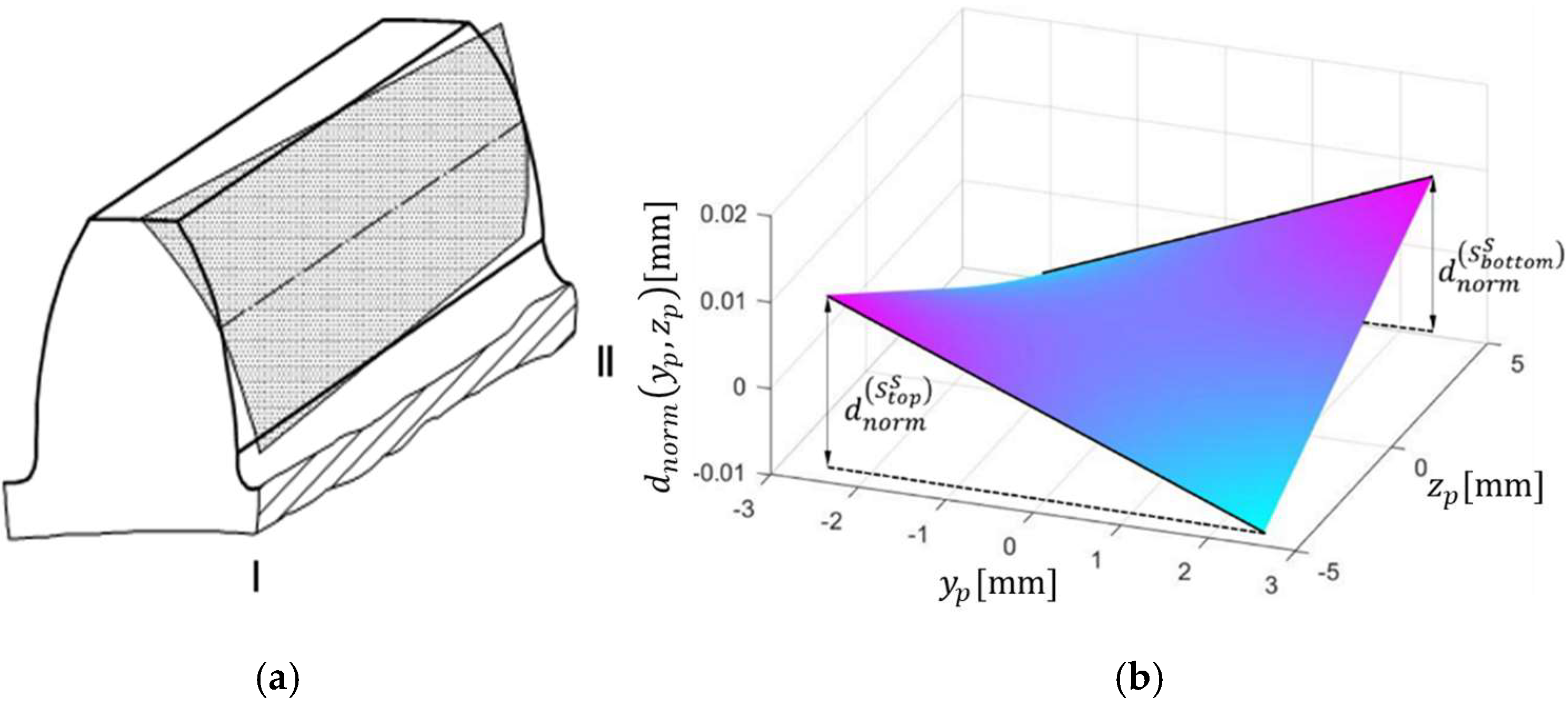
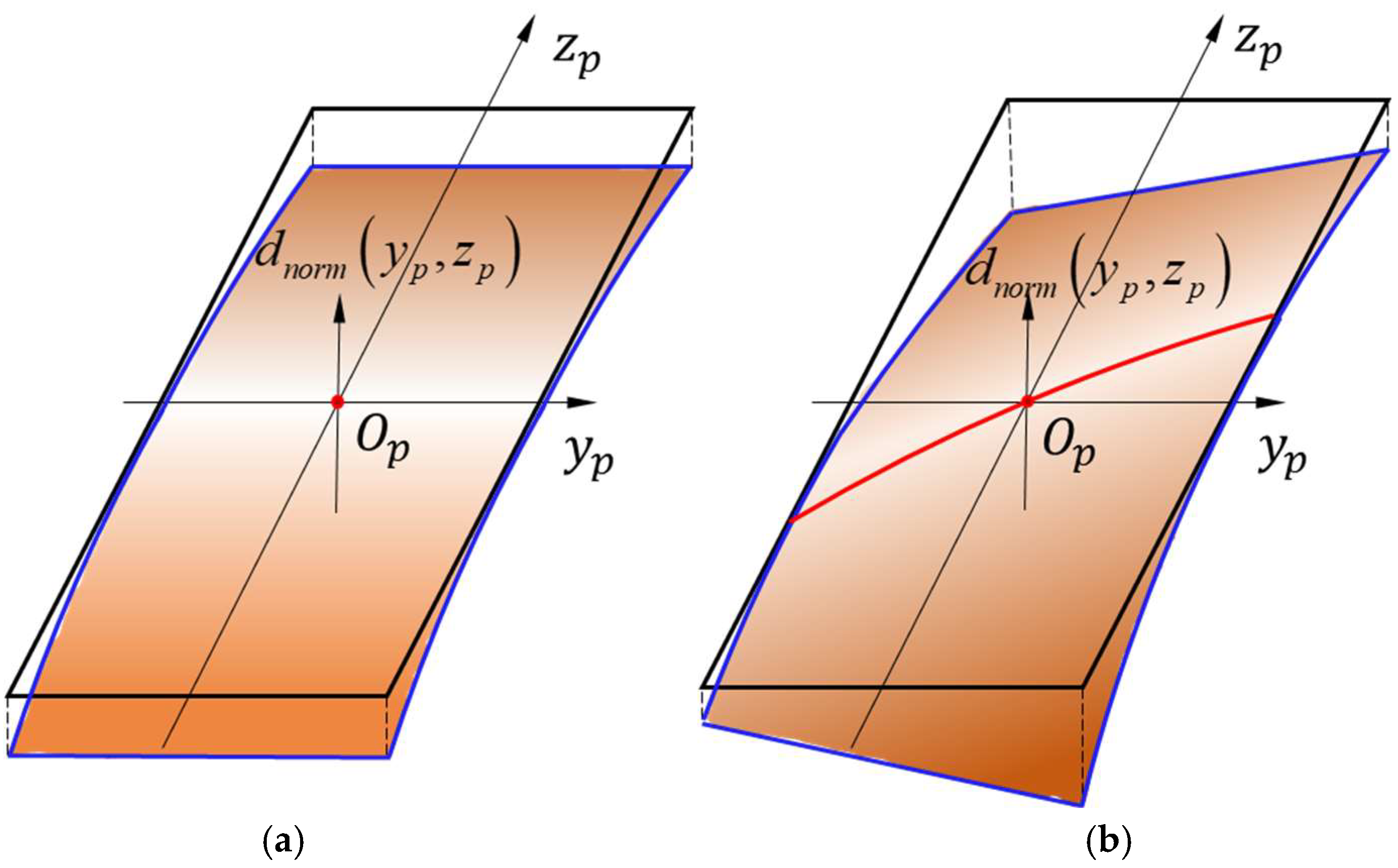
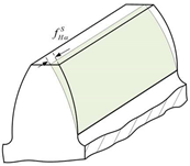
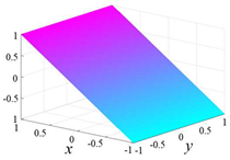
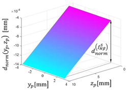
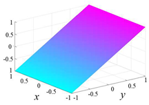
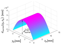
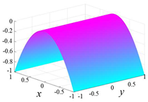
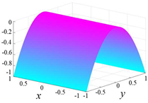
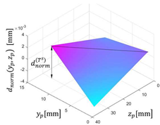
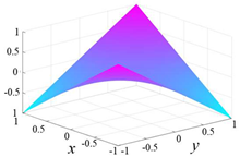
Flank twist is the result of the rotation of the transverse profile of the tooth flank along the helix. When there are slope deviations along the tooth profile and the helical line at the same time, and the deviation of the tooth tip is opposite to that of the tooth root, the twist phenomenon is characterized on the tooth flank, as shown in Figure 4a. Figure 4b shows the shape of the twist on the tooth flank in the meshing plane coordinate system, and its Legendre polynomial characterization function is

Figure 4.
The tooth flank twist in the gear coordinate system and the meshing plane coordinate system. (a) Flank twist. (b) Flank twist in the meshing plane.
From Equation (11), it can be seen that the Legendre expansion coefficients related to the tooth flank twist deviation have three influence coefficients: , and . Expanding the twist characterization function Equation (11), Equation (12) could be obtained.
where the first-order term represents the slope along the helical direction due to the twist, the first-order term represents the slope along the tooth profile direction due to the twist, and the second-order term represents the twist on the tooth flank, represented by .
The relationship between and tooth surface twist is
The expansion coefficient is closely related to the amount of twist. The greater amount of tooth flank twist, the larger the absolute value of .
4. Example of Tooth Flank Twist Measurement
4.1. Tested Gear
In order to verify that the characterization method of tooth flank twist is consistent with the evaluation results of tooth flank twist in ISO21771, so as to ensure the correctness of the method proposed in this paper, a measurement experiment is carried out. The parameters of the tested gear are shown in Table 3. The test gear was first roughed with a hobbing machine, and then modified with a worm grinding wheel.
Table 3.
Basic parameters of the test gear.
4.2. Measurement Results Based on ISO21771
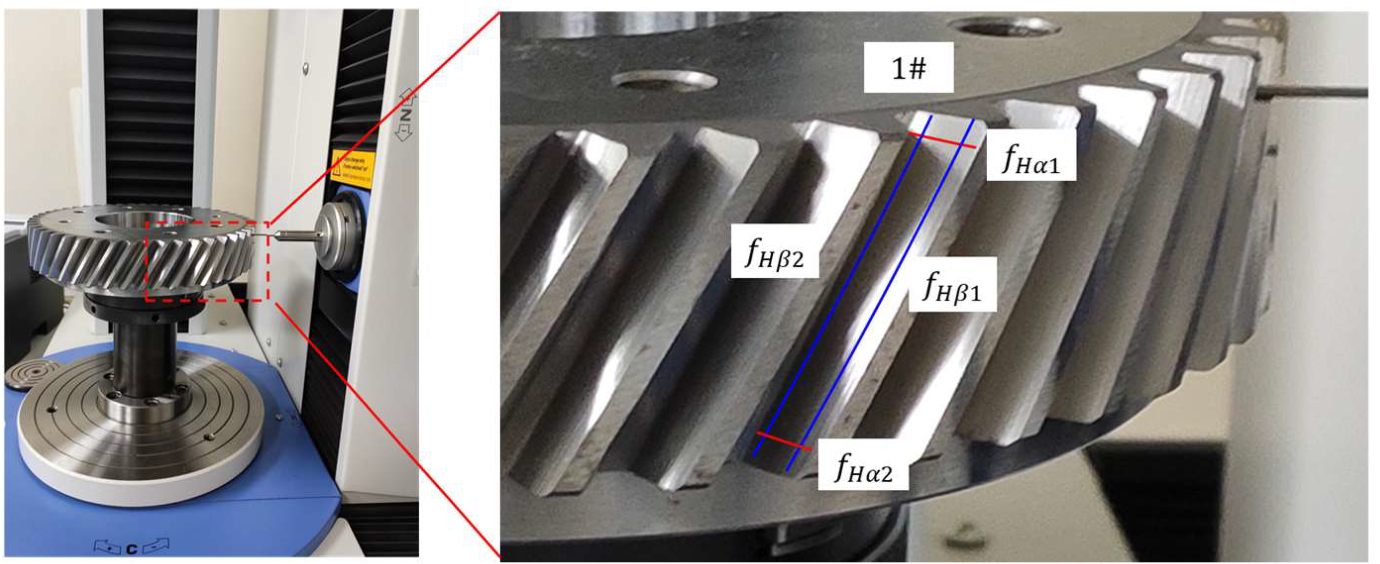
In this test, the gear measurement center P26 is used to measure the deviation of the tested gear based on ISO21771. As shown in Figure 5, the left and right tooth flanks of the 1# gear tooth were measured, and the transverse profile twist and helical line twist were used to calculate the twist deviation of the tooth flank.

Figure 5.
Using P26 to measure the test gear.
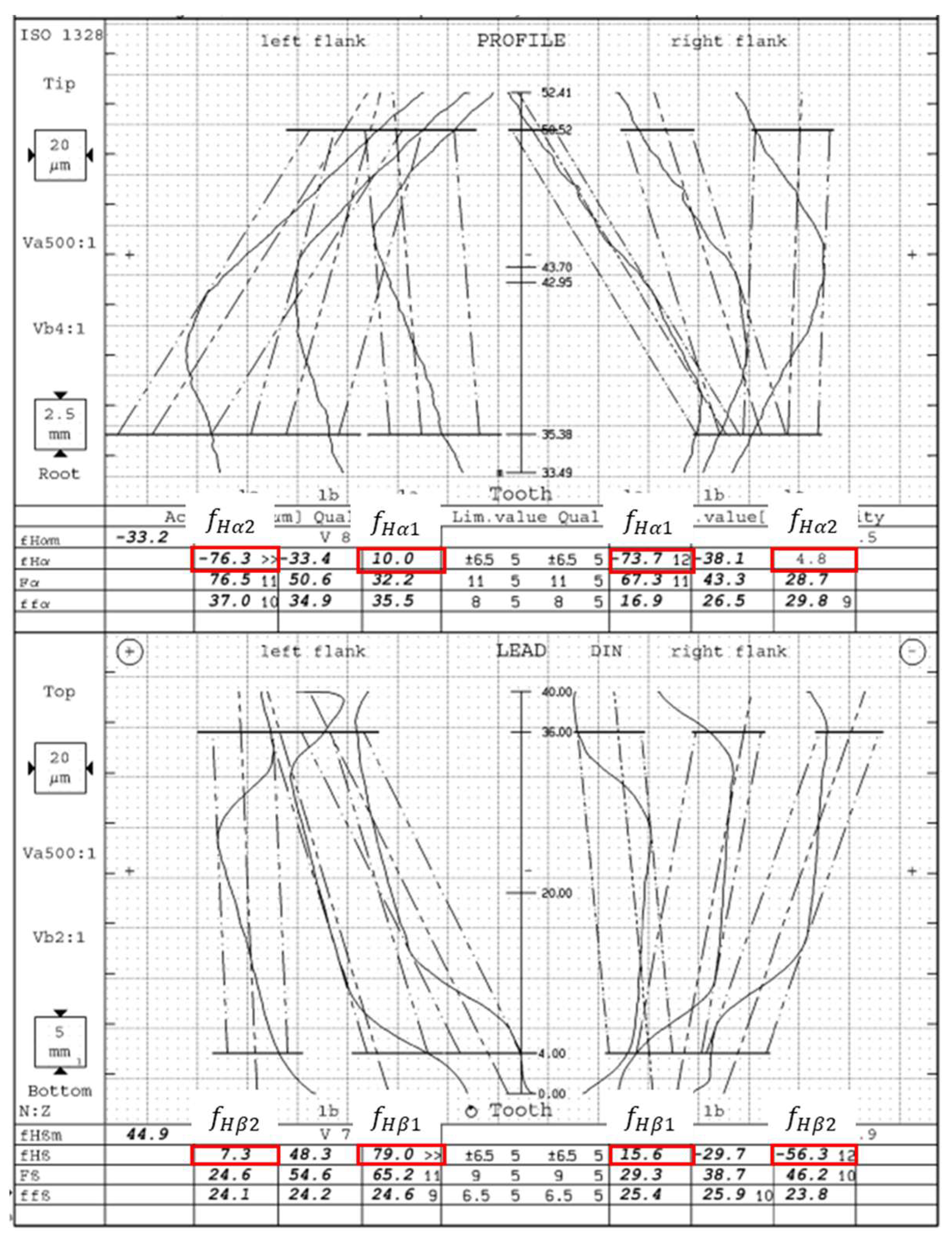
Figure 6 shows the measurement results of gear measuring center P26. The profile slope deviation and of 1# tooth are measured at the top and bottom of the tooth, and the helix slope deviation and are measured along the tooth tip and root. of the left tooth profile is −76.3 and is 10.0 . of the left tooth flank is 7.3 and is 79 . of the right tooth flank is −73.7 and is 4.8 . of the right tooth flank is 15.6 and is −56.3 . According to the evaluation method in ISO21771, the twist of the transverse profile of the left tooth flank is 86.3 and that of the right tooth flank is 78.5 . The twist of the flank line of the left tooth flank is 71.7 and that of the left tooth flank is 71.9 .
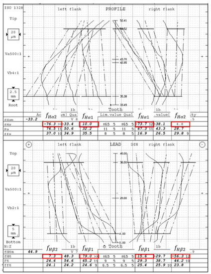
Figure 6.
Measurement results of gear measuring center P26.
4.3. Measurement Results of New Method
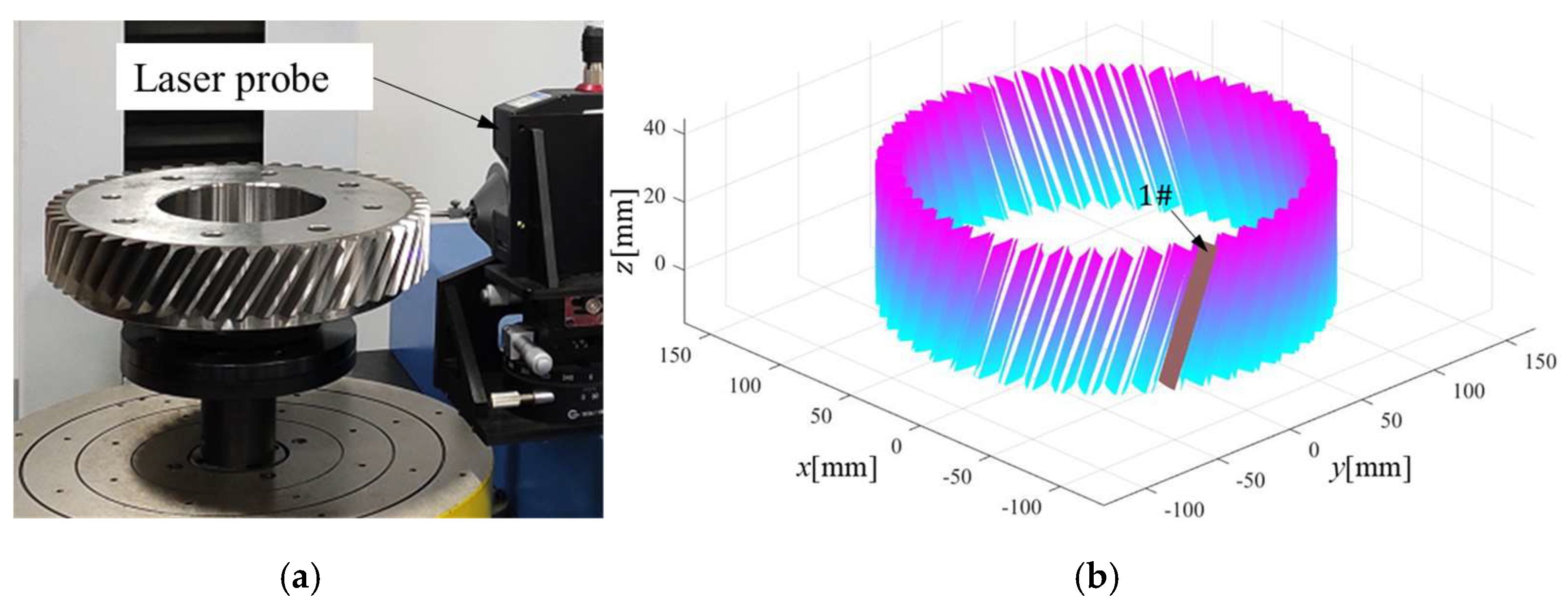
The measuring equipment of the twist characterization method proposed in this paper is the gear rapid measurement system based on structured light sensor developed by the Beijing University of technology, as shown in Figure 7a which can realize the rapid acquisition of 3-D point cloud of the gear, as shown in Figure 7b.

Figure 7.
Gear rapid measurement center and measurement of the tested gear. (a) Measuring gears by gear rapid measurement center. (b) Tooth flank measurement data.
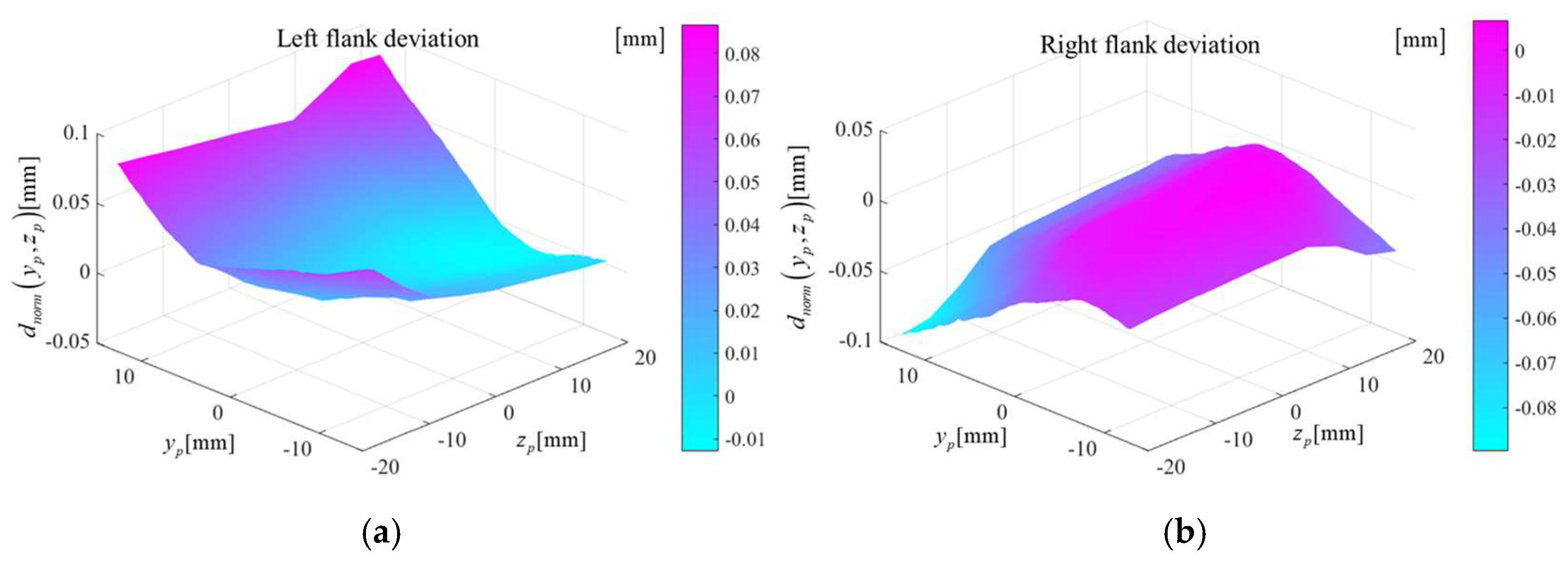
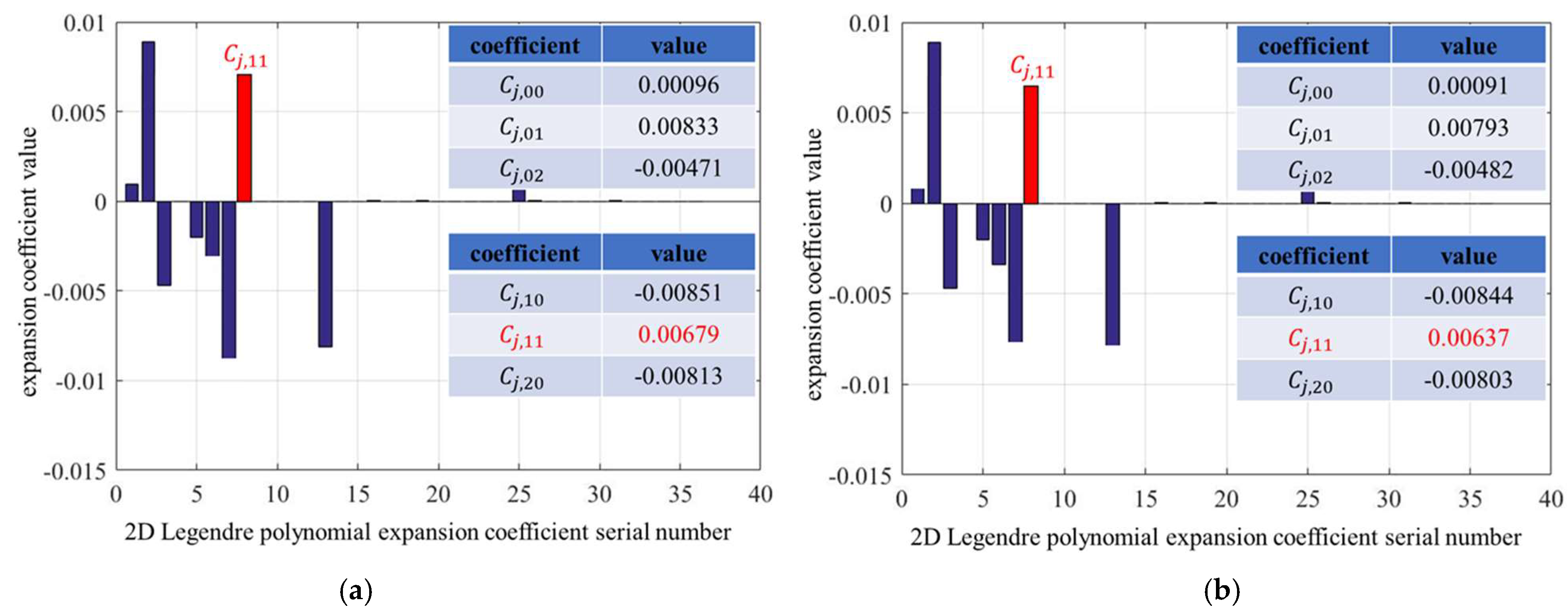
The topological deviation map of the tooth flank obtained by the structured light measurement is shown in Figure 8. Figure 8a shows the topological deviation of the left tooth flank, and Figure 8b shows that of the right tooth flank. The deviation is characterized by the method proposed in this paper to obtain various expansion coefficients. In this experiment, the 6th-order Legendre polynomial is used to characterize the deviation, and a total of 36 polynomial expansion coefficients are obtained. The specific values are shown in Figure 9. In Figure 9a, the expansion coefficient characterizing the twist of the left tooth flank is 0.00679, and the twist deviation can be calculated as 81.4 according to Equation (13). In Figure 9b, the expansion coefficient characterizing the twist of the left tooth flank is 0.00637. Similarly, the twist deviation can be calculated as 76.4 .

Figure 8.
Topological deviation map of tooth flank. (a) Left flank deviation. (b) Right flank deviation.
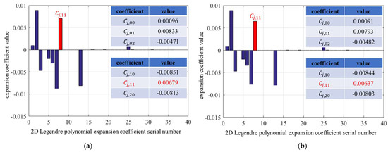
Figure 9.
2-D Legendre coefficients of the measurement. (a) 2-D Legendre coefficients of the left flank. (b) 2-D Legendre coefficients of the right flank.
4.4. Comparison
Table 4 shows the comparison between the measurement results of P26 and the method proposed in this paper.
Table 4.
Comparison of P26 results with the experimental results of this method.
It can be seen from the experiments in this part that for the left flank, the twist obtained by the proposed method is 81.4 . The twist of the transverse profile obtained on the P26 is 86.3 and the relative error is 5.67%. The twist of the flank line is 71.7 and the relative error is 13.5%. For the right flank, the twist is 76.4 . The twist of the transverse profile obtained from the P26 is 78.5 and the relative error is 2.67%. The twist of the flank line is 71.9 and the relative error is 6.25%. From the measurement results of the left and right tooth flank, it can be seen that there is a difference between the twist of the transverse profile and the twist of the flank line on the same tooth flank. It is hard to represent the same tooth flank twist with two different values. The tooth flank twist obtained by the proposed method combines the two factors of the tooth profile and the helix, and its value is between the twist of the transverse profile and the twist of the flank line. When the difference between the twist of the transverse profile and twist of the flank line is large, the tooth flank twist result of the new method is quite different from the two values. On the contrary, when the difference between the twist of the transverse profile and the twist of the flank line is small, the relative error between the tooth flank twist result of the new method and the two values is reduced. The proposed method is based on the characterization of the twist deviation of the entire tooth flank, which unifies the transverse profile and twist and the twist of the flank line in ISO21771, and realizes the evaluation of the twist with the entire tooth flank data.
5. Factors Affecting the Twist of the Tooth Flank in the Grinding Process
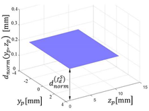
In the longitudinal modification processing of the helical cylindrical gear, when the conventional worm grinding wheel is used, the tooth flank twist will happen. An approximate model of the tooth flank twist of the involute helical spur gear during continuous grinding is proposed in recent research [2]. When the tooth flank is twisted during the machining process, the high point of each modification curve on the tooth flank moves along the normal contact profile according to the meshing principle. It leads to the result that the modification curves at the tooth top and root on the tooth flank are different, as the contact trace in Figure 1. Figure 10 shows the form of the longitudinal crowning modification on the tooth flank in the meshing plane coordinate system. Figure 10a is the designed flank and Figure 10b is the actual modified flank processing by the worm wheel grinding. After the flank is decomposed and characterized by the Legendre polynomials, the crowning and twist of the tooth flank can be separated.

Figure 10.
Theoretical modified flank and actual machining flank. (a) Theoretical modified flank. (b) Actual machining flank.
As shown in Figure 10a, the tooth flank is modified with a longitudinal crowning, and the designed modification is
In Equation (14), represents the opening size of the modification curve, which corresponds to the amount of longitudinal crowning , and represents the facewidth.
The modification flank is
In Equation (15), represents the base helix angle.
Equation (15) is equivalent to
The modification flank can be characterized by orthogonal polynomials as
where represents the coefficient of different types of tooth flank deviations, the term representing twist is .
Equation (18) can be obtained by combining Equations (13) and (17)
where, represents the width of the meshing area and its value is related to the modulus of the gear.
Equation (19) can be obtained from Equation (18).
From Equation (19), it can be seen that in the longitudinal crowning modification process, the parameter that characterizes the twist of the tooth flank is jointly affected by and . When increases, increases; increases, which means the normal modulus increases, increases; increases, increases; increases, decreases.
6. Conclusions
In this paper, a tooth flank twist characterization method was proposed based on orthogonal polynomials. It was found that the orthogonal polynomial expansion coefficient can characterize the tooth flank twist. Tooth flank twist unifies the twist of the transverse profile and the twist of flank line in ISO21771. Tooth flank twist is based on the definition of total tooth flank deviation, which is not limited to the direction of the profile or helix. evaluates the twist phenomenon based on the whole tooth flank.
Taking the worm wheel grinding process of the longitudinal crowning modification as an example, it was found that the factors related to the twist in the process are as follows. The larger twist will increase with the increasing of the base helix angle . The modification curve coefficient affects the crowning value of the modification curve. The larger twist is proportionate to the crowning value. The dimension of the contact area along the tooth profile rolling direction reflects the influence of the modulus on the twist. is also linear to the twist. The twist is inversely proportional to the facewidth.
Author Contributions
The contribution of B.Z. is proposing the new twist model and to verify the model. The contribution of B.Y. is building up the model of various parameters of the gear and the amount of twist. The contribution of Z.S. is to find the path of the contact points is a straight line. The contribution of Y.S. is to compile some of the figures. The contribution of G.W. is to provide some resources. All authors have read and agreed to the published version of the manuscript.
Funding
This research was funded by National Natural Science Foundation (52075005) and National Key R&D Program of China (2018YFB2001400).
Institutional Review Board Statement
Not applicable.
Informed Consent Statement
Not applicable.
Data Availability Statement
Not applicable.
Conflicts of Interest
No conflict of interest exits in the submission of this manuscript, and manuscript is approved by all authors for publication.
References
- Wang, Z.; Song, X.; He, M.; Li, G.; Zhu, W.; Geng, Z. Tooth surface model construction and error evaluation for tooth-trace modification of helical gear by form grinding. China Mech. Eng. 2015, 26, 2841–2847. [Google Scholar]
- Yu, B.; Kou, H.; Zhao, B.; Shi, Z.; Sun, Y.; Wu, G. Approximation model for longitudinal-crowned involute helical gears with flank twist in continuous generating grinding. Int. J. Adv. Manuf. Technol. 2021, 114, 3675–3694. [Google Scholar] [CrossRef]
- Tang, J.; Chen, X.; Luo, C. Contact analysis of spur gears based on longitudinal modification and alignment errors. J. Cent. South Univ. 2012, 43, 1703–1709. [Google Scholar]
- Hsu, R.H.; Wu, Y.R.; Tran, V.T. Manufacturing Helical Gears with Double-crowning and Twist-free Tooth Flanks using a Variable Pressure Angle Shaving Cutter. Proc. Inst. Mech. Eng. Part B J. Eng. Manuf. 2018, 233, 095440541771859. [Google Scholar] [CrossRef]
- Sohn, J.; Park, N. Modified worm gear hobbing for symmetric longitudinal crowning in high lead cylindrical worm gear drives. Mech. Mach. Theory 2017, 117, 133–147. [Google Scholar] [CrossRef]
- Walter, G. Twist Control Grinding (TCG). Gear Technol. 2017, 34, 48–53. [Google Scholar]
- Xiaoqing, T.; Dan, L.; Xiaoyong, H.; Haijun, L.; Jinag, H.; Lian, X. A topological flank modification method based on contact trace evaluated genetic algorithm in continuous generating grinding. Mech. Mach. Theory 2022, 172, 104820. [Google Scholar] [CrossRef]
- Wang, X.; Shi, Z. Evaluation system of gear accuracy based on full information. Sci. Sin. Tech. 2017, 47, 46–59. (In Chinese) [Google Scholar] [CrossRef]
- SO 1328-1: 2013(E); Cylindrical Gears—ISO System of Flank Tolerance Classification—Part 1: Definitions and Allowable of Value of Deviations Relevant to Flanks of Gear Teeth. International Organization for Standardization: Geneva, Switzerland, 2013.
- ISO21771; Gears—Cylindrical Involute Gears and Gear Pairs—Concepts and Geometry. British Standards Institution: London, UK, 2007.
- Shi, Z.; Fei, Y.; Xie, H. 100 years of gear measurement technology—Review & prospect. Chin. Eng. Sci. 2003, 5, 13–17. [Google Scholar]
- Willink, R. An accurate and consistent procedure for the evaluation of measurement uncertainty. Meas. Sens. 2021, 18, 100334. [Google Scholar] [CrossRef]
- Shi, Z.; Zhao, B.; Yu, B.; Guo, X. Characterization and Decomposition of Gear 3-D Deviation. J. Mech. Eng. 2022, 1–9. [Google Scholar]
- Mark, W. Performance-Based Gear Metrology Kinematictransmission—Deviation Computation and Diagnosis; John Wiley & Sons Ltd.: Hoboken, NJ, USA, 2013; pp. 31–67. [Google Scholar]
- Available online: http://kns.cnki.net/kcms/detail/11.2187.th.20220315.1844.020.html (accessed on 25 June 2022).
- Wang, Z.; Guo, D. Introduction to Special Functions; Science Press: Beijing, China, 1965; pp. 206–268. [Google Scholar]

Publisher’s Note: MDPI stays neutral with regard to jurisdictional claims in published maps and institutional affiliations. |
© 2022 by the authors. Licensee MDPI, Basel, Switzerland. This article is an open access article distributed under the terms and conditions of the Creative Commons Attribution (CC BY) license (https://creativecommons.org/licenses/by/4.0/).