Article

The Residual Stress and Deformation Control of TC4 Thin-Walled Outer Ring Components by Ultrasonic Regulation

1
School of Mechanical Engineering, Beijing Institute of Technology, Beijing 100081, China
2
Xi’an Electronic Engineering Research Institute, Xi’an 710100, China
*
Author to whom correspondence should be addressed.
Machines 2022, 10(8), 598; https://doi.org/10.3390/machines10080598
Submission received: 15 June 2022 / Revised: 12 July 2022 / Accepted: 20 July 2022 / Published: 22 July 2022
(This article belongs to the Section Advanced Manufacturing)

Abstract

:
The deformation problem caused by the excessive residual stress has brought great challenges to the high-precision machining and geometrical stability of thin-walled components. Aiming to ensure the verticality within 0.012 mm after the processing and forming of a certain type of outer ring components, this paper firstly employs the ultrasonic critical refraction longitudinal wave (LCR wave) detection method to test the residual stress distribution in the key process. Additionally, the stress elimination effect of cryogenic stress relief treatment and the effect of residual stress on vertical deformation are analyzed. After that, combined with the self-developed ultrasonic stress relief (USR) equipment, the ultrasonic regulation treatment was used to replace the heat treatment stress relief process for the processing. The results show that after wire cutting and milling, excessive residual stress induces deformation of components, and USR method can eliminate machining residual stress more efficiently and quickly. As the whole component has torsional deformation along the cross section, the hole position at the upper and lower end faces is changed, which leads to the change in verticality. Finally, based on the results of X-ray diffraction (XRD), the potential microscopic mechanism of stress relief by ultrasonic treatment is analyzed. This study provides guidance for ultrasonic residual stress regulation to achieve the high-precision outer ring thin-walled components.

1. Introduction

Target seeker components for aerospace and weapons can search, identify and track the target independently and give the control signal required for guidance. It is the core device for guiding weapons, radars which detection, tracking targets and generating attitude adjustment parameters. Additionally, the coordinator is an important part of the seeker components for its manufacturing level determines the seeker detection ability, tracking accuracy. Owing to the increasing requirements for form accuracy and surface quality, TC4 titanium alloy has been increasingly used to manufacture thin-walled outer ring parts of coordinator, on account of its low density, high specific strength, corrosion resistance, good fatigue resistance and thermal processing performance [1,2]. However, the forming process of the outer ring component has the characteristics of a large amount of material removal, a thin wall after multiple machining, and the presence of types of machining holes in a component; in addition, TC4 alloy has poor plasticity and ductility at room temperature [3]. With the severe plastic deformation caused by high temperature, high strain rate, thermal stress and phase transformation in the machining process of milling and wire cutting, it is inevitable that uneven residual stress field distribution in the components is introduced, thus inducing the deformation of the components in the next machining processes [4,5]. The residual stress after the final forming of the outer ring has a balance effect; that is, it will slowly release and lead to the internal stress state of the components tending to be balanced as a whole, which promotes the further secondary deformation of the components. For thin-walled outer rings with high precision dimensional accuracy requirements, the deformation caused by residual stress is a great challenge to its geometrical stability and high efficiency machining.
Many scholars have studied different processing technologies for thin-walled components, expounded the generation and release mechanism of residual stress, and investigated the influence of residual stress distribution on deformation. Yue et al. pointed out that the main factors affecting the milling deformation of thin-walled parts are residual stress, milling force and milling heat, workpiece clamping conditions, tool path and material properties [6]. The grazing-incidence X-ray diffraction method and dynamic interferometry has been employed by Chen et al. to establish the relationship between cutting residual stress and deformation of thin-walled components, which indicate that residual stress is proportional to the deformation in a certain range of cutting depth [7]. It is beneficial for cutting deformation layer and residual stress control when reducing the cutting depth. Li et al. studied the influence of different milling depths on the residual stress distribution of thin-walled components [8]. It was found that the residual stress and the maximum compressive stress depth of the machined surface decreased with the decrease in the cutting depth, which usually produced large residual compressive stress at the edge of the cutting path, and the initial residual stress before machining had a great influence on the redistribution of residual stress on the subsequent machined surface. Through laser shock prefabrication residual stress and thermal fatigue test, He et al. proved that the relaxation mechanism of thin blade residual stress is plastic recovery caused by thermal stress activation dislocation, grain boundary movement and annihilation [9]. Zhu et al. carried out milling tests on TC4 thin plate and found that the surface of TC4 thin plate was residual compressive stress within 100 μm after milling. An exponential model based on residual stress distribution was established to predict deflection deformation of TC4 thin plate [10].
For the deformation prediction of thin-walled components, Liu et al. proposed a milling deformation prediction method for thin-walled deep-cavity parts based on finite element method, which consider the deflection of tool-workpiece system [11]. The milling test and simulation results of waveguide cover were compared, and the maximum deformation error is less than 15%. Unit birth and death technology was used by Luo to simulate the milling process of integral thin-walled parts, analyzing the influence of milling parameters and clamping layout on machining deformation, and predicting the machining deformation of thin-walled parts [12]. Huang et al. studied the bending deformation of large thin-walled plate under the coupling effect of the initial residual stress and machining residual stress by combining the test and finite element method. The results showed that the initial residual stress is the main factor for the deformation of the components, and the deformation caused by machining residual stress accounted for 10% of the total deformation of the components [13]. By analyzing the influence of surface stress and initial stress on bending deflection, a residual stress-deformation model was established on thin-walled frame by Liao et al. to predict the deformation of components. Additionally, the accuracy of the model was verified by changing the residual stress distribution in components by shot peening and milling [14].
At present, the more difficult problem is that we are often unknown about the initial residual stress distribution in mechanical components and the residual stress generated by various manufacturing processes. In fact, the superposition of the initial residual stress and the processing stress makes the residual stress distribution in the components hard to predict. The uneven distribution of residual stress within the components has become the root of influencing the deformation and restricting its geometrical stability. Therefore, it is urgent to master the residual stress distribution of components under different process parameters to better analyze the machining deformation law of components. Effective and nondestructive quantitative measurement of residual stress is also the basis for subsequent stress reduction and homogenization.
Common nondestructive testing methods include X-ray method [15,16], neutron diffraction method, magnetic method, eddy current method and ultrasonic method [17,18]. Among them, the X-ray method is mostly used in physicochemical environment, which can only measure the surface stress. Chemical cleaning is required on the surface of the tested material. The test results are affected by grain size and surface roughness, and certain radiation protection is needed. Similarly, it is difficult to use the neutron diffraction method for on-site detection because of the expensive construction and operation costs, and the strict radiation protection requirements. The magnetic method is only applicable to ferromagnetic materials, and the detection accuracy is greatly affected by the microstructure of the material.
Due to the structural characteristics of actual thin-walled components, such as weak stiffness, easy deformation and high milling rejection rate, the in situ nondestructive testing of residual stresses in the structure has always been a technical problem to be solved in the field of mechanical manufacturing. Compared with other detection methods, ultrasonic residual stress detection is more suitable for machining field environment. The ultrasonic detection method is based on the change in propagation velocity, frequency, amplitude and other parameters of ultrasonic wave when propagating in the component with residual stress, which can realize the characterization of residual stress. Additionally, ultrasonic critically refracted longitudinal wave method, which is based on acoustic elasticity theory, becomes the main method of ultrasonic residual stress detection [19,20]. In recent years, a lot of research has been conducted on the feasibility of the ultrasonic LCR wave method for residual stress detection, and the improvement of detection accuracy is also studied. Yashar Javadi et al. performed an investigation on the ultrasonic method to detect the residual stress of a welded plate, with the authors pointing out that the stress measured by the LCR wave method is the average stress within a certain depth range [21]. Abbas Habibalahi et al. conducted a study on 2024 aluminum alloy residual stress detection, and they found that the ultrasonic detection signal obtained by neural network data fusion algorithm can effectively improve the accuracy of residual stress detection [22]. Liu et al. studied the influence mechanism of grain orientation on ultrasonic propagation, and introduced the characterization factor of grain orientation to establish a plane stress component-velocity decoupling model [23]. Additionally, the filled coupling agent detection probe was designed to detect the welded aluminum alloy plate. Combined with the orifice method, it was proved that this method can effectively reduce the influence of temperature change on the sound velocity and improve the detection accuracy. By testing the 304 stainless steel plate, Yang et al. indicated the distance between the transmitting probe and the receiving probe should be large enough to accurately identify the LCR wave [24]. In the detection process of outer ring thin-walled components, the residual stress distribution after different processing can be measured by designing the detection wedge and selecting the appropriate detection probe.
At the same time, with the increasing requirements for machining accuracy and service performance, it is often necessary to control and eliminate the residual stresses of components. Therefore, many scholars have studied the reduction in residual stresses in various types of mechanical components. The commonly used methods to eliminate residual stresses include stress relief heat treatment [25], vibration time effect method [26,27], ultrasonic impact method [28], pulse magnetization method [29,30], etc. However, these methods have limitations while removing stress, such as high energy consumption, a long cycle of stress relief heat treatment, it difficulty in controlling the deformation of components after stress relief. It is difficult to use the vibration method to work on components with high stiffness and high natural frequency. It is easy to deform thin-walled components when spectrum harmonic vibration is used. The ultrasonic impact method may damage the surface of components, and the pulse magnetization method is only applicable to ferromagnetic materials. In order to meet the processing technology and deformation accuracy requirements of thin-walled components, an efficient and reliable stress removal method should be adopted. It is necessary to explore a new normal temperature stress removal process to remove the residual stress of thin-walled parts with high efficiency. Due to the obvious stress reduction effect at room temperature, the stress relief by ultrasonic regulation has gradually become the focus of research [31].
In summary, the existing residual stress test method or calculation simulation and the deformation research under residual stress are mostly aimed at the samples or simple components rather than the finished thin-walled components. Since the current stress relief annealing and other processes make it difficult to quantitatively control the deformation after stress relief of the outer ring of seeker coordinators, the underlying mechanisms of stress elimination remain unclear.
In this paper, the LCR wave method is employed to detect the machining process and stress removal process of thin-walled outer ring components. The residual stress distribution under different processes is analyzed, which lays the foundation for subsequent deformation control and optimization of process parameters. Meanwhile, an ultrasonic residual stress relief process suitable for TC4 thin-walled outer ring component of seeker coordinator was proposed, and the corresponding experiment was carried out with a self-made ultrasonic platform.
The residual stress was removed by ultrasonic vibration treatment. After the introduction of large residual stress, the ultrasonic stress removal method was used to eliminate the excessive stress amplitude, homogenize the overall residual stress distribution, and reduce the subsequent processing deformation. Finally, the key design verticality of the outer ring components of the seeker coordinator was ensured to be within 0.012 mm. The dislocation changes and single-point residual stresses of the samples before and after ultrasonic stress removal were measured by XRD diffraction technology, and the potential stress release mechanism of ultrasonic stress removal process was further analyzed.

2. Testing and Ultrasonic Stress Relieving Devices

2.1. Ultrasonic Critical Refraction Longitudinal Wave Detection Method

The residual stress test by ultrasonic critical refraction longitudinal wave method is based on the principle of acoustic elasticity; that is, the velocity of propagation sound would be decreased by tensile residual stress and increased by compressive residual stress. By measuring the sound propagation time in the calibration area and the tested area, the measured stress can be achieved.
By simulating the propagation depth of critical refraction longitudinal wave at different frequencies, Liu et al. fitted the relationship between detection frequency and detection depth [32]. The detection frequency is 5 M, so the detection depth is about 1.08 mm. Under the condition when the distances between excitation and receiver transducers (L), wedge width (W), and frequency (F) are fixed, average three-dimensional stress in the range can be calculated. If the detection area of the calibration sample is assumed to be zero stress area, the measured stress value is residual stress value.

2.2. Measuring Equipment

Figure 1a shows the ultrasonic residual stress detector developed by Beijing Institute of Technology. Additionally, the system uses the cross-correlation algorithm written in C++ language, which brings the detection accuracy within ±20 MPa. In order to test the curved and flat areas of the outer ring components, the bottom of the detection wedge is machined to fit closely to the curved and flat surfaces, as shown in Figure 1b.
According to GB/T 32073-2015, tensile samples for calibration of the stress coefficient K were produced. A WDW-200E microcomputer-controlled electronic universal testing machine is used to load the tensile specimens, and the tensile results show that the yield strength of TC4 is 956 MPa. The tensile coefficient is measured in its elastic range, the stress loading range is 0–500 MPa, with each stress loading rise step is 50 MPa, and fit stress coefficient K is 10.2 MPa/ns.
For quantitatively observing the vertical deformation of components after machining and stress reduction, the size measurement was carried out by Global 9208 contact measuring instrument of Hexagon company. The change in dislocations is characterized by BRUCKER D8 ADVANCE instrument. The scanning rate is 6°/min, with scanning angle ranging from 30° to 80°.

2.3. USR System

Based on the machining process and structure characteristics of outer ring components, an USR system was self-developed, as shown in Figure 2. The size of the horn is designed according to the frequency and size of the ultrasonic transducer, and the flange plate is set at the position of the vibration node. The combined horn and transducer are fixed on the L-shaped fixture to surround the components. Each front face of the horn can be fully attached to the surface of the outer ring component, and grease is smeared to better couple the transfer of energy.
The L-shaped fixed plate is connected with the convex platform of the support base center by spring, and the tensile spring can ensure that the horn is always closely in contact with the component with a certain compression force. The wood blocks were filled inside the components to prevent the inward deformation caused by stress release. During stress relief regulation, the effective output power of ultrasonic generator supply was greater than 100 W.

3. Results

3.1. Residual Stress Detection of Outer Ring Components Forming Process

The main processing and heat treatment processes of six TC4 thin-walled outer ring components of seeker coordinator were selected for testing, as shown in Figure 3a. The rod-shaped TC4 raw material was cut into sheet embryo, and then the P1 state was obtained by wire cutting. After stress relief annealing, rough milling, cryogenic stress relief treatment, semi-finishing milling, wire cutting cavity, and the second cryogenic treatment were performed, until final finish milling. The three-dimensional coordinates of the components after milling and heat treatment are measured, and the residual stress is tested to analyze the relationship among residual stress, deformation and verticality of the components. Detection of residual stresses as shown in Table 1.
Residual stress detection points and three-dimensional measurement dimensions are shown in Figure 4a,b respectively. M1 to M6 are the difference between the detection value and the design value, and M7 is vertical. In the P3/P4 detection, the left convex platform of the outer ring component is used as the detection positioning reference. Four regions near the position of the outer borehole and two regions inside are selected for stress detection. The position below the detection surface is denoted as A, and the position above is denoted as B. As the inner ring is slotted and the detection space is limited, it can only detect three locations outside during P5 and P7.
Average residual stresses (ARS) of components 1# to 6# treated by different processes are shown in Figure 5. Rough milling residual stress is greater than semi-finishing milling residual stress, and two cryogenic treatments can effectively reduce the residual stress distribution. The average residual stress can be reduced to less than 20% of the yield strength by cryogenic destressing treatment.
The test results show that the stress distribution from components 1# to 6# after each detection process is basically the same. Therefore, taking component 1# as an example, the distribution of residual stress and the corresponding deformation under different processes are analyzed. The residual stress on all detection points is shown in Figure 6a. By observing the outer ring components of the seeker after rough milling and semi-finishing milling, the stress distribution at each point has a large deviation from the average stress value. There is also a certain range of stress fluctuations at the same detection point. After cryogenic treatment, the residual tensile stress amplitude can be effectively reduced, and the overall stress distribution can be homogenized. Stress amplitude decreases more in regions with larger initial stress after destressing cryogenic treatment.
The deformation of the component 1# from rough milling to the second cryogenic treatment is shown in Figure 6b. Since there is no fixed tooling to limit the deformation in the process of cryogenic stress relief, the component in the free state also induce secondary deformation during stress is released. The variation trends of the distance between the left and right/upper and lower and the inner and outer radius are not consistent. The maximum deformation size after rough milling is M4 (outer part radius of lower end), followed by M2 (distance between upper and lower end of inner part) and M6 (outer part radius of upper end). The verticality error is caused by the inward contraction of the outer radius of the upper and lower ends. After the first cryogenic treatment, the deformation of M4 further increased, and the verticality also increased from 0.3133 mm to 0.3344 mm. When the component started semi-precision milling with low stress state, the deformation of each measurement position is significantly reduced and more balanced. After the second cryogenic treatment, the deformation of M3 (inner part radius of lower end) is greater, resulting in the increase in the verticality from 0.0103 mm to 0.0147 mm. It can be seen that the error of machining verticality changes with the overall deformation caused by stress release. The release of stress leads to the deformation of the radius of the upper and lower circles of the whole component, and at the same time, it makes the left and right end faces move up and down. The whole component has torsional deformation along the cross section, so that the hole position at the upper and lower end faces is changed; that is, the verticality is changed.

3.2. Ultrasonic Residual Stress Control Test

Through the residual stress detection analysis of the outer ring component, it can be found that the residual stress distribution can be homogenized in the stress removal process, but the secondary deformation caused by stress release increases the risk of vertical dimension deviation. Therefore, combined with the ultrasonic stress elimination technology, the machining process of the outer ring component is redesigned, as shown in Figure 3b. Six components (from 7# to 12#) were also selected for the ultrasonic stress relief test. Under the condition of keeping the original machining process unchanged, the self-developed USR system was used for releasing stress treatment to replace the heat treatment process. In order to improve the residual stress removal efficiency and obtain components with lower residual stress distribution within a certain period of time, it is necessary to use reasonable control time and times. First, the residual stress of the wire-cut TC4 small test is detected, and then the USR system is used for stress relief treatment. It was found that the residual stress can be effectively released when the single actuator excitation is maintained at 100 W. When analysis the stress-relieving parameters, the #1 component is used as the test piece in the constant temperature air-conditioned room (26 °C). After the stress-relieving treatment is carried out every 5 min, stress relief is carried out until the residual stress drops to within 10% of the yield strength, which is considered to be under low stress level, and thus obtain ideal residual stress relief parameters. The control process parameters are shown in Table 2, and the ultrasonic treatment time is gradually reduced by combining the overall stress distribution and wall thickness of the components after wire cutting blank, rough milling and wire cutting cavity. The actual resonant frequency will deviate when the front-end load is applied to the 20 KHz ultrasonic transducer. After the components are installed in the USR system, the impedance analyzer is used to measure the resonant frequency of each ultrasonic transducer and excite it. In order to comprehensively grasp the residual stress distribution, it is also detected on the surface of the workpiece before drilling. The residual stress detection point is shown in Figure 7.
The average residual stresses (ARS) of components (from 7# to 12#) after different processes are shown in Figure 8. The stress distribution trends of the six components are roughly the same. In the forming process, the maximum residual tensile stress distribution is introduced when the components cutting frame from the round billet. Except for 10# and 11#, the residual stresses of other components after rough milling are larger than those after wire cutting.
The stress distribution of components 7# to 12# formed by various processing processes is basically the same. Component 7# is selected to analyze the distribution of residual stress and the corresponding deformation law after different processing processes, as shown in Figure 9a. After the removal materials of P1/P3/P5, the stress values at each detection point fluctuated greatly compared with the average stress value. Three ultrasonic destressing treatments can significantly reduce the residual stress peak value, and the stress value of the component in state of low stress distribution will also decrease after the subsequent processing. The dimensional deformation measurement of the components is shown in Figure 9b. Along with the decrease in residual stress, the changes in M1 (distance between left and right end of inner part) and M2 (distance between upper and lower end of inner part) and the radius of upper and lower circles (M3–M6) are not consistent. The wire cutting blank and the first stress removal did not drill holes in the component. The angle of vertical line between left and right face and upper and lower face is regarded as verticality. Although the residual stress decreased greatly, the verticality only decreased from 0.0184 mm to 0.0178 mm. After rough milling, the component was drilled, and the verticality was 0.0225 mm. When the second stress removal was finished, the overall component contracted inward, and the verticality increased significantly to 0.1006 mm. The verticality of the component in the low stress state after semi-finishing milling is only 0.0147 mm, and the overall component size error is small. The stress was increased to 0.016 mm after direct wire cutting without stress elimination. This also indicates that the subsequent machining deformation error can be reduced when the machining is in a low stress state.

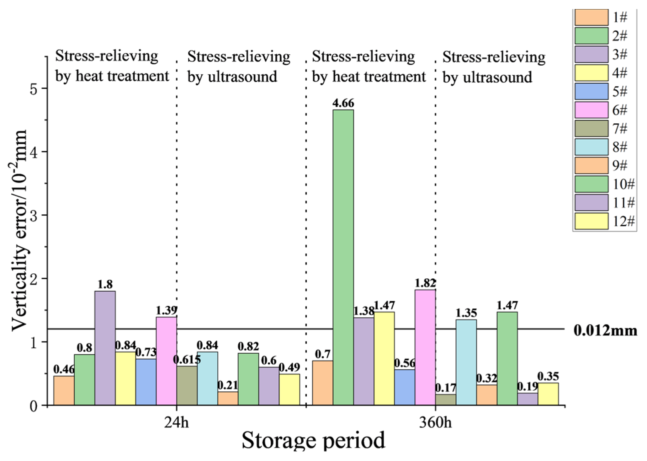
3.3. Comparison of Stress Elimination Methods

In the forming process of components 1# to 12#, two treatments were used to eliminate residual stresses after wire cutting and rough milling residual stresses. The residual stress distribution of each component after rough milling and subsequent treatment is listed to compare stress reduction effect of ultrasonic treatment and cryogenic treatment, as shown in Table 3.
The residual stress reduction rate α represents the decreasing trend in residual stress before and after stress regulation, and its calculation formula is defined as follows:
α = | R S 0 | | R S 1 | | R S 0 |
where R S 0 is the average residual stress before stress regulation, and R S 1 is the average residual stress after stress regulation.
The residual stress reduction rate of ultrasonic-treated components is higher than cryogenic treated components. The maximum stress reduction rate of components after cryogenic treatment can reach 61.8%, while the maximum stress reduction rate after ultrasonic stress relief can reach 98.2%. Both cryogenic treatment and ultrasonic stress relief can effectively eliminate residual stresses, but the effect of ultrasonic treatment is obviously superior to that of cryogenic destressing. Moreover, the cryogenic process takes 360 min, while the ultrasonic destressing takes only 25 min, which greatly improves the production efficiency. Additionally, the maximum residual stress of components 1# to 6# before rough milling is obviously larger than that of 7# to 12#. This may be due to the fact that the residual tensile stress cannot be completely reduced by annealing before rough milling, and the stress is redistributed during subsequent rough machining, thus the newly introduced stress is superimposed with the original stress. Components 7# to 12# have been treated by ultrasonic stress relief before rough milling, so the maximum residual tensile stress is relatively small.
The change in the verticality after milling of all components is shown in Figure 10, and the design requirement is 0.012 mm. Measurements of heat treatment components were carried out 24 h after the formation of a standstill, with two component size deviations (3# to 6#). When standing for 360 h, the measurement was carried out again. The secondary release of residual stress led to the deformation again. The verticality of 3# and 6# changed from 0.018 mm and 0.0139 mm to 0.0138 mm and 0.0182 mm. Additionally, the 2# and 4# component size also occurred vertical out-of-tolerance phenomenon. It can also be seen that the stress distribution level of component s# to 6# is not the same after finishing milling. Component 2# may contain large stress, which releases more stress and causes great change in verticality. After redesigning the forming process of the outer ring components, the verticality with residual stress elimination by ultrasonic method after finishing milling is less than 0.012 mm. Store, for 360 h only, components 2# and 4# with a vertical degree small margin, and greatly improve the component shape-keeping ability.

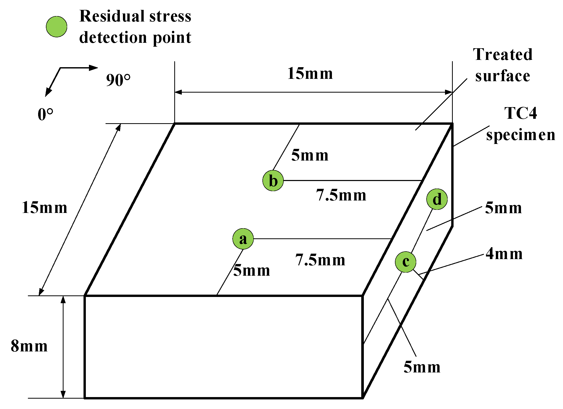
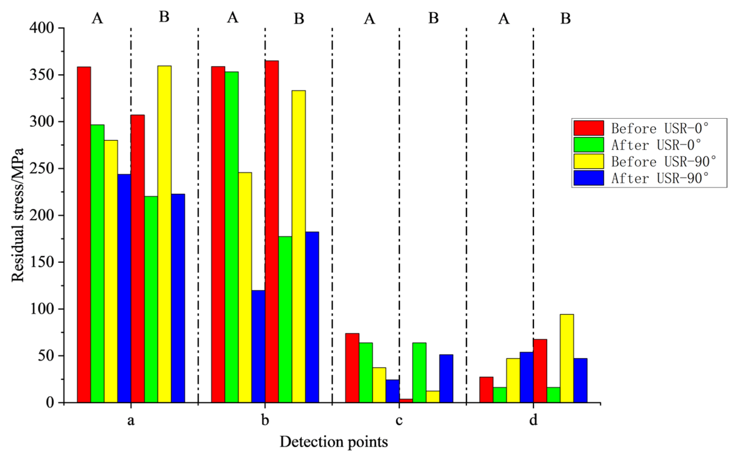
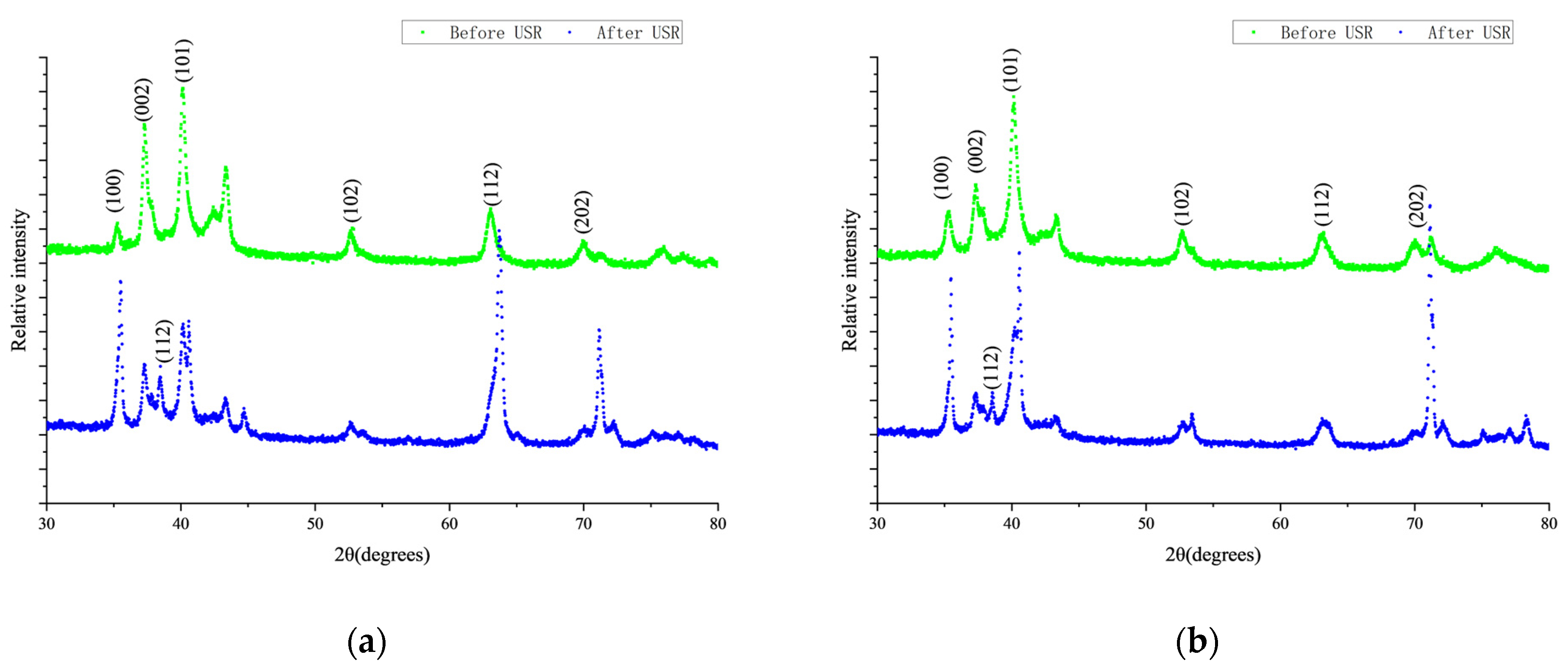
3.4. Mechanism of Ultrasonic Method to Eliminate Residual Stress

As a novel stress relief technology, vibration stress relief and stress relief by heat treatment has gradually attracted the attention of scholars [33,34]. However, the current research on USR has primarily focused on the effectiveness of stress relief, rather than underlying mechanisms of stress relief. It can be considered that the residual stress is generated due to the elastic adjustment caused by plastic deformation in different regions of the component, so the residual stress belongs to elastic strain energy.
The residual stress relief is the result of the transformation of the residual elastic strain into irrecoverable inelastic strain (including plastic strain, creep, etc.). From the microscopic perspective, the actual stress in the material is complex with the interaction of many dislocations, as well as the influence of vacancies and other point defects, grain boundaries, and sub-grain boundaries. Therefore, the actual residual stress in the material is a comprehensive result of lattice distortion. It is necessary to design a test and prove the microscopic mechanism of ultrasonic stress release.
Two test blocks prepared by wire cutting on TC blanks are recorded as A and B test blocks, as shown in Figure 11. Due to the small size of the test block, LCR wave method cannot be used to measure residual stress, so an X-ray detector is used to detect stress at local points. Two points (a/b) in the center of the treated surface and the center of thickness (c/d) were selected for residual stress measurement. Firstly, the stress of the original test block was measured, and then the two test blocks were placed directly at the front end of the 20 KHz transducer for pressing, and ultrasonic stress relief was performed: among them, the A test block received ultrasonic treatment, for 5 min and the B test block received ultrasonic treatment for 10 min. After the treatment was complete, the residual stress of the test block was detected again.
As shown in Figure 12, before ultrasonic treatment, the stress at points a and b of blocks A and B was large, and the stress at points c and d was small. The overall stress after USR was significantly reduced, which was consistent with the test results of Gu et al. [35]. After 5 min of ultrasonic stress treatment, A block in the 0° direction from a point to d point stress are reduced, but the decline is not large. In the 90° direction, only the stress at point d increases from 43.1 MPa to 53.9 MPa, which should be caused by the stress balance. Similarly, the stress of a, b and d points with larger stress in 0° and 90° direction of B block decreased significantly after 10 min ultrasonic stress relief treatment. The initial stress at point c is only 3.9 MPa and 12.5 MPa. When the stress of the whole component decreases, the stress at c increases to balance the overall internal stress. The two points of c/d are located at 4 mm depth below the regulated surface, i.e., at 1/2 of the overall thickness. The change in stress also indicates that the USR not only reduces and homogenizes the stress on the regulated surface, but also changes the stress of the whole component.
The X-ray diffraction patterns of A and B are shown in Figure 13a,b respectively. Before USR, the main diffraction peaks of A and B blocks were (101), and after ultrasonic treatment, it became (112) and (202), respectively; that is, the diffraction peaks shifted to high angles. The half-width of the main peak values of each diffraction curve was processed by Jade 5.0 software, and it was found that the peak values after regulation mainly decreased.
Comparing the XRD patterns of A and B blocks before and after treatment, it was found that the main diffraction peak value and the width of each derivative peak changed. The change in X-ray diffraction peak width is mainly caused by lattice distortion and grain refinement, and the relationship is as follows:
δ s = 2 ε tan θ
where δ s is the change in diffraction peak width caused by lattice distortion, θ is the diffraction angle. That is, the half width height of diffraction peak width can be observed to analyze the strain changes before and after ultrasonic stress relief. The relationship between dislocation density ρ and strain ε in the material is [36]:
ρ = 14.4 ε 2 / b 2
where b is the Bergs vector.
Dynamic evolution of dislocation occurs in the process of USR. After USR treatment, the dislocation density decreases and the stress is released. When the material contains large residual stress, there are massive dislocation structures in the microstructure. The ultrasonic treatment process brings enough energy to the component, and the dislocation is activated after absorbing enough energy to overcome the potential energy barrier and realize sliding motion. With the continuous action of ultrasonic external load, dislocation annihilation leads to the decrease in the overall dislocation density, which eventually reduces the lattice distortion of the material and relaxes the overall residual stress.

4. Conclusions

In view of the problem that the verticality error of the seeker outer ring component is difficult to guarantee after forming, and the geometrical stability is poor, this paper uses the ultrasonic critical refraction longitudinal wave method to detect the residual stresses in the key processing procedures of the twelve TC4 thin-walled components, and analyzes the deformation of the component combined with three coordinate measuring instruments. Then, the processing technology is redesigned by using a self-developed USR system combined with outer ring components. The conclusions are as follows:
(1)
Cryogenic treatment can effectively reduce the residual stress in milling, but it will inevitably cause deformation of components. Due to the release of residual stress, the radius of the upper and lower circles of the component will be deformed, and at the same time, it makes the left and right end faces move up and down. The torsion deformation of the whole component occurs along the section caused the change in the verticality.
(2)
The ultrasonic stress relief method can quickly and effectively eliminate residual stress in component processing. Compared with the original cryogenic destressing treatment, ultrasonic treatment can increase the stress reduction rate from about 60% to about 90%, and the destressing time is much shorter than that of cryogenic treatment, which improves the processing efficiency. USR treatment can make components in a stressless distribution which leads to less deformation in subsequent processing and improves the machining accuracy. The components manufactured by ultrasonic destressing method meet the design precision, and the shape-keeping ability is improved, which makes it possible for the ultrasonic destressing process to replace cryogenic destressing process.
(3)
Combined with the X-ray diffraction and X-ray stress detection analysis of small-scale tests, it can be found that the USR treatment activates the dislocation movement by transmitting enough energy to the component. The continuous annihilation of dislocation leads to the decrease in the overall dislocation density, and finally reduces the lattice distortion of the material and relaxes the residual stress in the component. Subsequently, we will further study the molecular dynamics method to establish a model containing typical residual stress distribution. Simulation of ultrasonic regulation to further reveal the evolution process of microscopic defects during stress release.

Author Contributions

Writing—original draft, methodology, formal analysis, project test, W.-Y.S.; writing—review and editing, project administration, methodology, C.-G.X.; visualization, project administration, methodology, Q.-X.P.; grammar review, methodology, P.-L.L.; project test, L.W., grammar review, T.Y. All authors have read and agreed to the published version of the manuscript.

Funding

This research was funded by National Natural Science Foundation of China, grant number 51975050 and China’s National Key R&D Programmes (NKPs), grant number 2021YFF0600500.

Institutional Review Board Statement

Not applicable.

Informed Consent Statement

Not applicable.

Data Availability Statement

Data are contained within the article.

Conflicts of Interest

The authors declare no conflict of interest.

Abbreviations

αResidual stress reduction rate
b Bergs vector
ρ Dislocation density
θ Diffraction angle
ε Strain
LCR waveUltrasonic critical refraction longitudinal wave
USRUltrasonic stress relief
XRDX-ray diffraction
ARSAverage residual stresses

References

  1. Jin, H.X.; Wei, K.X.; Li, J.M.; Zhou, J.Y.; Peng, W.J. Research development of titanium alloy in aerospace industry. Chin. J. Nonferrous Met. 2015, 25, 280–292. [Google Scholar]
  2. Bewlay, B.P.; Weimer, M.; Kelly, T.; Suzuki, A.; Subramanian, P. The Science, Technology, and Implementation of TiAl Alloys in Commercial Aircraft Engines. MRS Proc. 2013, 1516, 49–58. [Google Scholar] [CrossRef]
  3. Wang, J.; Xu, X.F.; Huang, F.; Xiao, X.; Xu, L. Research on (Super) Plasticity and Microstructure of TC4 Alloy at Medium-low Temperature. Hot Work. Technol. 2017, 46, 40–48. [Google Scholar]
  4. Meng, L.; Atli, M.; He, N. Measurement of equivalent residual stresses generated by milling and corresponding deformation prediction. Precis. Eng. 2017, 50, 160–170. [Google Scholar] [CrossRef]
  5. Longhui, M.; Ning, H.; Yinfei, Y.; Wei, Z. Measurement of Surface Residual Stresses Generated by Turning Thin-Wall Ti6Al4V Tubes Using Different Cutting Parameters. Rare Met. Mater. Eng. 2015, 44, 2381–2386. [Google Scholar] [CrossRef]
  6. Yue, C.; Zhang, J.; Liu, X.; Chen, Z.; Liang, S.Y.; Wang, L. Research progress on machining deformation of thin-walled parts in milling process. Hangkong Xuebao/Acta Aeronaut. Et Astronaut. Sin. 2022, 43, 525164. [Google Scholar]
  7. Chen, Y.; Ma, S.; Kong, J.; Huang, W. Study on the surface grain state, residual stress and their influence on the deformation of thin-walled parts under ultra-precision cutting. Int. J. Mod. Phys. B 2020, 34, 2050272. [Google Scholar] [CrossRef]
  8. Li, B.; Jiang, X.; Yang, J.; Liang, S.Y. Effects of depth of cut on the redistribution of residual stress and distortion during the milling of thin-walled part. J. Mater. Process. Technol. 2015, 216, 223–233. [Google Scholar] [CrossRef]
  9. HE, W.; LI, X.; NIE, X.; LI, Y.; LUO, S. Study on Stability of Residual Stress Induced by Laser Shock Processing in Titanium Alloy Thin-Components. Acta Metall. Sin. 2018, 54, 411–418. [Google Scholar]
  10. Zhu, W.H.; Wang, Z.Y.; Ren, J.X.; Zhou, J.H. Study on Milling Residual Stress and Deformation of TC4 Titanium Alloy Thin Plate Parts. Modul. Mach. Tool Autom. Manuf. Technol. 2020, 70–72. [Google Scholar]
  11. Si-Meng, L.; Xiao-Dong, S.; Xiao-Bo, G.; Dou, W. Simulation of the deformation caused by the machining cutting force on thin-walled deep cavity parts. Int. J. Adv. Manuf. Technol. 2017, 92, 3503–3517. [Google Scholar] [CrossRef]
  12. LUO, Y. Machining Deformation Prediction and Research of Influence Factors for Large Thin-Walled Workpiece; Harbin Institute of Technology: Harbin, China, 2017; pp. 57–63. (In Chinese) [Google Scholar]
  13. Huang, X.; Sun, J.; Li, J. Finite element simulation and experimental investigation on the residual stress-related monolithic component deformation. Int. J. Adv. Manuf. Technol. 2015, 77, 1035–1041. [Google Scholar] [CrossRef]
  14. Liao, K.; Zhang, X.D.; Che, X.F.; Chen, H.; Gong, H. Construction and analysis of mechanic model of deformation for Al alloy thin-walled component. J. Harbin Inst. Technol. 2018, 50, 172–178. (In Chinese) [Google Scholar]
  15. Perić, M.; Nižetić, S.; Garašić, I.; Gubeljak, N.; Vuherer, T.; Tonković, Z. Numerical calculation and experimental measurement of temperatures and welding residual stresses in a thick-walled T-joint structure. J. Therm. Anal. 2020, 141, 313–322. [Google Scholar] [CrossRef]
  16. Nitschke-Pagel, T. Recommendations for the measurement of residual stresses in welded joints by means of X-ray diffraction—results of the WG6-RR test. Weld. World 2020, 65, 589–600. [Google Scholar] [CrossRef]
  17. Xu, C.G.; Li, P.L. Stress-free Manufacturing Technology. J. Mech. Eng. 2020, 56, 113–132. [Google Scholar]
  18. Wang, N.; Luo, L.; Liu, Y. Research progress on stress measurement technology for metal components. Chin. J. Sci. Instrum. 2017, 38, 2508–2517. [Google Scholar]
  19. Acevedo, R.; Sedlak, P.; Kolman, R.; Fredel, M. Residual stress analysis of additive manufacturing of metallic parts using ultrasonic waves: State of the art review. J. Mater. Res. Technol. 2020, 9, 9457–9477. [Google Scholar] [CrossRef]
  20. Pan, Q.; Shao, C.; Xiao, D.; Pan, R.; Liu, X.; Song, W. Robotic Ultrasonic Measurement of Residual Stress in Complex Curved Surface Components. Appl. Bionics Biomech. 2019. [Google Scholar] [CrossRef] [Green Version]
  21. Javadi, Y.; Akhlaghi, M.; Najafabadi, M.A. Using finite element and ultrasonic method to evaluate welding longitudinal residual stress through the thickness in austenitic stainless steel plates. Mater. Des. 2013, 45, 628–642. [Google Scholar] [CrossRef]
  22. Habibalahi, A.; Dashtbani Moghari, M.; Samadian, K.; Mousavi, S.S.; Safizadeh, M.S. Improving pulse eddy current and ultrasonic testing stress meas-urement accuracy using neural network data fusion. Sci. Meas. Technol. Iet 2015, 9, 514–521. [Google Scholar] [CrossRef]
  23. Liu, H.B.; Liu, T.R.; Li, Y.P.; Wang, Y.Q. Surface Residual Stress Measurement of Metal Material Using Ultrasonic. J. Mech. Eng. 2021, 57, 118–125. [Google Scholar]
  24. Investigation of Uncertain Factors on Measuring Residual Stress with Critically Refracted Longitudinal Waves. Appl. Sci. 2019, 9, 485. [CrossRef] [Green Version]
  25. Fiocchi, J.; Colombo, C.; Vergani, L.M.; Fabrizi, A.; Timelli, G.; Tuissi, A.; Biffi, C.A. Heat Treatments for Stress Relieving AlSi9Cu3 Alloy Produced by Laser Powder Bed Fusion. Materials 2021, 14, 4184. [Google Scholar] [CrossRef]
  26. Zhang, Q.; Yu, L.; Shang, X.; Zhao, S. Residual stress relief of welded aluminum alloy plate using ultrasonic vibration. Ultrasonics 2020, 107, 106164. [Google Scholar] [CrossRef]
  27. Song, H.; Gao, H.; Wu, Q.; Zhang, Y. Effects of segmented thermal-vibration stress relief process on residual stresses, mechanical properties and microstructures of large 2219 Al alloy rings. J. Alloy. Compd. 2021, 886, 161269. [Google Scholar] [CrossRef]
  28. Chen, J.; Chu, J.; Jiang, W.; Yao, B.; Zhou, F.; Wang, Z.; Zhao, P. Experimental and Numerical Simulation to Study the Reduction of Welding Residual Stress by Ultrasonic Impact Treatment. Materials 2020, 13, 837. [Google Scholar] [CrossRef] [Green Version]
  29. Shao, Q.; Kang, J.; Xing, Z.; Wang, H.; Huang, Y.; Ma, G.; Liu, H. Effect of pulsed magnetic field treatment on the residual stress of 20Cr2Ni4A steel. J. Magn. Magn. Mater. 2019, 476, 218–224. [Google Scholar] [CrossRef]
  30. Yan, M.; Wang, C.; Luo, T.; Li, Y.; Feng, X.; Huang, Q.; Yang, Y. Effect of Pulsed Magnetic Field on the Residual Stress of Rolled Magnium Alloy AZ31 Sheet. Acta Metall. Sin. (Engl. Lett.) 2020, 34, 45–53. [Google Scholar] [CrossRef]
  31. Guo, X.L.; Li, H.W.; Wang, H.L.; Geng, J.G. Influence of different residual stress regulation methods on the deformation of aluminum alloy box cover. Mod. Mach. 2021, 5, 24–28. [Google Scholar]
  32. Liu, Y.; Liu, E.; Chen, Y.; Wang, X.; Sun, C.; Tan, J. Study on Propagation Depth of Ultrasonic Longitudinal Critically Refracted (LCR) Wave. Sensors 2020, 20, 5724. [Google Scholar] [CrossRef]
  33. Xu, L.Y.; Zhu, J.; Jing, H.Y.; Zhao, L.; Lv, X.Q.; Han, Y.D. Effects of deep cryogenic treatment on the residual stress and mechanical properties of electron-beam-welded Ti–6Al–4V joints. Mater. Sci. Eng. A 2016, 673, 503–510. [Google Scholar] [CrossRef]
  34. Ren, X.; Zhou, W.; Xu, S.; Yuan, S.; Ren, N.; Wang, Y.; Zhan, Q. Iron GH2036 alloy residual stress thermal relaxation behavior in laser shock processing. Opt. Laser Technol. 2015, 74, 29–35. [Google Scholar] [CrossRef]
  35. Gu, B.-P.; Hu, X.; Lai, J.-T.; Jin, Z.-D.; Zhou, H.; Yang, Z.-S.; Pan, L. Effects of high-frequency vibration on quenched residual stress in Cr12MoV steel. J. Mater. Res. 2016, 31, 3588–3596. [Google Scholar] [CrossRef]
  36. Bangping, G.; Xiong, H.; Guanhua, X.; Jintao, L.; Long, P. Microcosmic Mechanism of High-Frequency Vibratory Stress Relief Based on Dislocation Density Evolution. Rare Met. Mater. Eng. 2018, 47, 2477–2482. [Google Scholar]
Figure 1. Wave propagation path of ultrasonic testing: (a) Residual stress detector; (b) Wedge.
Machines 10 00598 g001
Figure 2. USR system: 1 is Support foundation, 2 is Ultrasonic transducer, 3 is L-shaped fixed plate, 4 is TC4 horn, 5 is Support wood block, 6 is Outer ring component, and 7 is Ultrasonic power.
Machines 10 00598 g002
Figure 3. Detection and residual stress elimination process of outer ring components. (a) traditional machining process of TC4 thin-wall outer ring; (b) ultrasonic machining process of TC4 thin-wall outer ring.
Machines 10 00598 g003
Figure 4. Description of three coordinate measuring position g: (a) Schematic diagram of residual stress detection point; (b) Description of three coordinate measuring position: M1 is distance between left and right end of inner part, M2 is distance between upper and lower end of inner part, M3 is Inner part radius of lower end, M4 is Outer part radius of lower end, M5 is Inner part radius of upper end, M6 is Outer part radius of upper end, and M7 is Verticality of connection between upper–lower holes and left–right holes.
Machines 10 00598 g004
Figure 5. Average residual stress distribution of 1# to 6#.
Machines 10 00598 g005
Figure 6. Residual stress distribution and deformation of 1# under different processes: (a) Residual stress; (b) Deformation.
Machines 10 00598 g006
Figure 7. Schematic diagram of residual stress detection points under USR treatment.
Machines 10 00598 g007
Figure 8. Average residual stress distribution of 7# to 12#.
Machines 10 00598 g008
Figure 9. Residual stress distribution and deformation of 7# under different processes: (a) Residual stress; (b) Deformation.
Machines 10 00598 g009
Figure 10. Comparison of verticality geometrical stability.
Machines 10 00598 g010
Figure 11. Test block size and X-ray stress detection point diagram.
Machines 10 00598 g011
Figure 12. Residual stress changes before and after USR.
Machines 10 00598 g012
Figure 13. XRD diffraction patterns before and after ultrasonic treatment: (a) 1#; (b) 2#.
Machines 10 00598 g013
Table 1. Description of residual stress detection.
Detection Process FlowDetection PositionSingle-Point Stress Detection TimesDetection Position
Original processing technologyPlane and surface3The average of three detection values of a single point is regarded as the residual stress value of the point.
USR processing technologyPlane and surface
Table 2. Control process parameter.
Manufacturing ProcessAverage
Excitation Frequency /KHz
Single
Incentive Time/min
Ultrasonic Regulation TimesSingle
Actuator
Excitation Power/W
Ultrasonic Regulation Temperature/°C
P2-First Ultrasonic
Stress Relief
19.6325210026
P4-Second Ultrasonic
Stress Relief
19.00251100
P6-Third Ultrasonic
Stress Relief
19.08101100
Table 3. Control process parameter heat treatment destressing vs. ultrasonic destressing.
Manufacturing ProcessMaximum Residual Stress before Rough Milling/MPaMaximum Stress after Stress Removal/MPaStress Reduction Rate α (%)Stress Relief Time/min
1#43224256.1360
2#46419058.6360
3#43218461.8360
4#41418662.1360
5#41618658.7360
6#43619057.4360
7#3164098.225
8#2807291.825
9#2528092.525
10#2747486.725
11#2727294.725
12#3847894.025
Publisher’s Note: MDPI stays neutral with regard to jurisdictional claims in published maps and institutional affiliations.

