Article

Multi-Analogy Innovation Design Based on Digital Twin

1
School of Mechanical Engineering, Hebei University of Technology, Tianjin 300130, China
2
National Technological Innovation Method and Tool Engineering Research Center, Tianjin 300130, China
3
Yueqing Institute of Technological Innovation, Yueqing 325600, China
4
Department of Mechanical Engineering, University of Manitoba, Winnipeg, MB R3T 5V6, Canada
*
Author to whom correspondence should be addressed.
Machines 2022, 10(8), 652; https://doi.org/10.3390/machines10080652
Submission received: 13 May 2022 / Revised: 14 July 2022 / Accepted: 29 July 2022 / Published: 4 August 2022
(This article belongs to the Special Issue Design Methods for Mechanical and Industrial Innovation)

Abstract

:
Analogy-based design is an effective approach for innovative design. However, existing research on analogy design mainly focuses on methods to form innovative schemes, without considering feasibility or practicality in applications. This research proposes a multi-analogy innovation design (M-AID) model based on analogy in both design-centric complexity (DCC) and solution of inventive problems (TRIZ). To improve practicality, digital twin (DT) is introduced to apply real design information, manufacturing production data, and maintenance information in the design process. The method includes six steps: (1) analyze a target product based on users and market requirements to synthesize general function requirements; (2) acquire analogy function source using knowledge base and patent base; (3) call digital twin resources to obtain real product data for the design; (4) reduce the complexity of the design system after fusion using DCC theory; (5) use TRIZ to solve problems of design conflicts; and (6) evaluate design solutions according to product requirements. The current proposed method enhances the design scheme feasibility and reduces the number of iterations from the conceptual scheme to the final scheme in the design process, thus improving the efficiency of the innovative design process. The applicability of the currently proposed method is demonstrated through exemplification of innovative design of a dust removal system for a solar panel.

1. Introduction

Analogy-based design (ABD) is a creative thinking/reasoning method from epistemology. Existing successful examples are referred and analogized as source and inspiration to solve relevant problems in innovation design [1,2,3]. Analogy-based design involves identifying similar functions or behaviors in existing products to obtain innovative principles and schemes through scenario analysis. The correlations among product structure (S) −> behavior (B) −> function (F) are mapped to establish a classical SBF model [4]. The analogy can be combined with solution of inventive problems (TRIZ) by scenario analysis to explore unforeseen potentials by the traditional design method to be accounted for in the innovative design [5]. Normative theory of analogy-based design (also known as model-based analogy) can transfer design principles from source cases to target problems [6]. A design process of complex systems can also be availed by analogy between mechanical and biological systems [7].
Although there are different studies of the analogy design method, existing analogy design research mainly focuses on the formation of design schemes, whereas it leaves out the feasibility or practicality in applications. This is because most of the above studies stay at the level of subjective analogy, only focusing on the qualitative description of the similarity between source design and target design, but lack of understanding of the actual situation of similar systems.
To this gap, this paper proposes a method to combine digital twin (DT) technology with the analogy design process for enhancing the quantitative thinking during the analogy design process so that to improve the practical feasibility of design schemes. During the analogy design process not only the similarity of the system but also the manufacturing, and maintenance data between the digital model and physical prototype of source systems can be considered by designers. The practical relevance of the new design is thus substantially promoted.
The concept of twins first appeared in the Apollo project in the United States. The National Aeronautics and Space Administration (NASA) built a model of space vehicles using ground twin of space aircraft. The concept of digital twin (DT) was proposed for its application model and to identify its advantages and impact on national strategic objectives [8]. DT is discussed further in the context of Industry 4.0, and the conceptual explanation and development prospects of DT are elaborated upon [9]. For product lifecycle management, DT is defined as virtual digital representation equivalent to the physical product that helps reduce uncertainties in product development [10]. Digital twin technologies provide an effective way to improve authenticity of information in design process. Extensive studies have used DTs to improve product design. For example, DT was used in design planning and identification, conceptual design, specific design, detailed design, and virtual verification [11]. A product DT was applied to collect required data in an iterative design process of complex systems [12]. A baseline DT object-oriented framework was obtained to facilitate the collaboration of different DT classes to provide benefits above and beyond what is provided by individual DTs [13].
It can be seen that researchers have made some contributions to the overall framework and mode of digital twin-driven product design. However, there is no research that combines digital twin technology with an analogy design concept to make contributions to product innovation design. This study believes that it is of great research significance to combine digital twinning technology with analogical design so as to carry out innovative de-sign of products according to existing product knowledge, data and historical experience.
The combination of DT technology and analogical design is a new pathway for innovative design. On this basis, this research proposes a multi-analogy innovation design (M-AID) model in which design-centric complexity (DCC) for reducing the complexity system and TRIZ for solving problems. To improve practicality, DT is introduced to apply real design information, manufacturing production data, and maintenance information in analogy design process. Thus, the currently proposed model enables product design to meet customer requirements and the manufacturing process. Combining digital twin technology and the analogy process to integrate product information, manufacturing data, and maintenance information, this research improves innovation design feasibility or practicality.
The contributions of this research are as follows:
  • A multi-analogy innovation design method is proposed by combining analogy theory, DT, DCC and TRIZ.
  • The currently proposed M-AID process model improves the practical feasibility of innovative schemes through DT to integrate data pertinent to customer requirements, the manufacturing process, etc, in the design process.
  • The currently proposed model improves design efficiency, shortens the design cycle, and saves resources for product innovation process.
The remaining context of the paper is outlined as follows. Section 2 introduces the relevant tools and theoretical framework for the currently proposed M-AID process model. The process model of M-AID (not an intelligent retrieval method) is described in Section 3. Section 4 demonstrates the application procedure and results of the currently proposed M-AID process model for specific projects. Section 5 evaluates the proposed method and solution. Conclusions are drawn and intended future studies are briefed in Section 6.

2. Related Works

This section introduces the theoretical framework for the currently proposed M-AID process model.

2.1. Analogy Design

With analogy, similarity in specific characteristics for two processes or designs are identified to cast forward the successful design concept/technique of one process or design to the design of the other. Analogy design is an effective innovation method to apply analogy reasoning in product design [14]. Classic analogy design concept is indicated in Figure 1. It uses an existing successful scheme as design source and required design as design target to identify their similarity to avail design solution [15,16]. Assuming that initial and final states of source design are A and B in Figure 1, initial and final states of target design are A and B , respectively. There are relations of β and β between initial and final states, that is, A generates B through β and A generates B through β . At the same time, there is a certain similarity α between A and A , and thus β is adaptive for β . In target design, ideal design B can be obtained according to A and β with reference to similarity α between B and B .
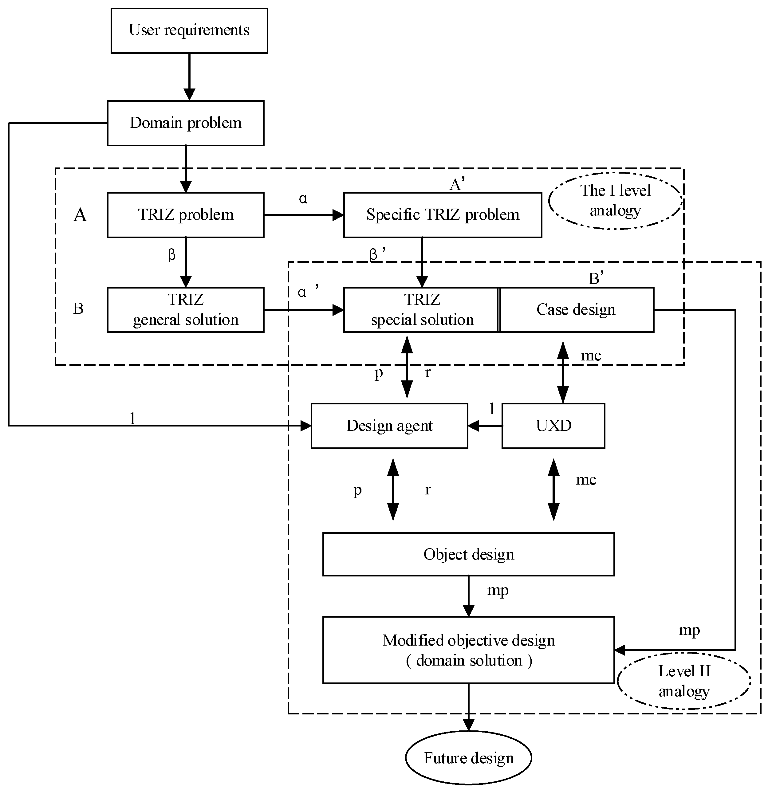
On this basis, Tan et al. [17] proposed a two-stage analogy model, as shown in Figure 2, which combines TRIZ and an episodic memory module to solve domain problems for innovative conceptual solutions.
In Figure 2, the process of first level analogy is similar to Figure 1, and the results of the analogy serve as innovative design scenarios, that is, the TRIZ special solution and case design are references for future design. In the second level analogy, unexpected discoveries (UXDs) generate a new target through the design agent, and pass it to object design via matching to derive the modified objective design. Design agent proposes multiple UXDs based on its own design experience, understanding of domain problems and the scenarios provided, and constantly revises the object design. Final objective designs are domain solution. In the process of second level analogy, l indicates learning, p represents perception, r refers to determination, m c denotes matching, and m p implies mapping.
An analogy framework can interpret and cast forward core concepts into the design context for new products in analogy design [18]. The correlation between the analogy source and target problem solving can be quantitatively expressed by a product similarity function matrix for product innovation using TRIZ [15]. Analogy design methods can also help explain design immobilization [19]. Murphy et al. [20] proposed a patent-based method for an alternative analogue search function carrier. Liu et al. [15] proposed a conceptual design process model based on TRIZ and functional analogy using a similarity matrix to quantitatively specify similarity of functions in analogy process and screen analogy results. Jia et al. [14] proposed a R-SBF analogy design model that integrates design knowledge flow, structure, behavior, and function to promote analogy design for the process of knowledge retrieval via research.
In spite of progress in research on analogy design, existing research on analogy design focuses on only constructing conceptual schemes based on similar knowledge, structure, behavior, and function of the product. Consequential pertinence of the schemes for practical applicability should also be improved. To this objective, this study engages digital twin technology in context of analogy design to improve the feasibility of design solution via digitalizing physical information in the analogy design process.

2.2. Digital Twin Knowledge Base

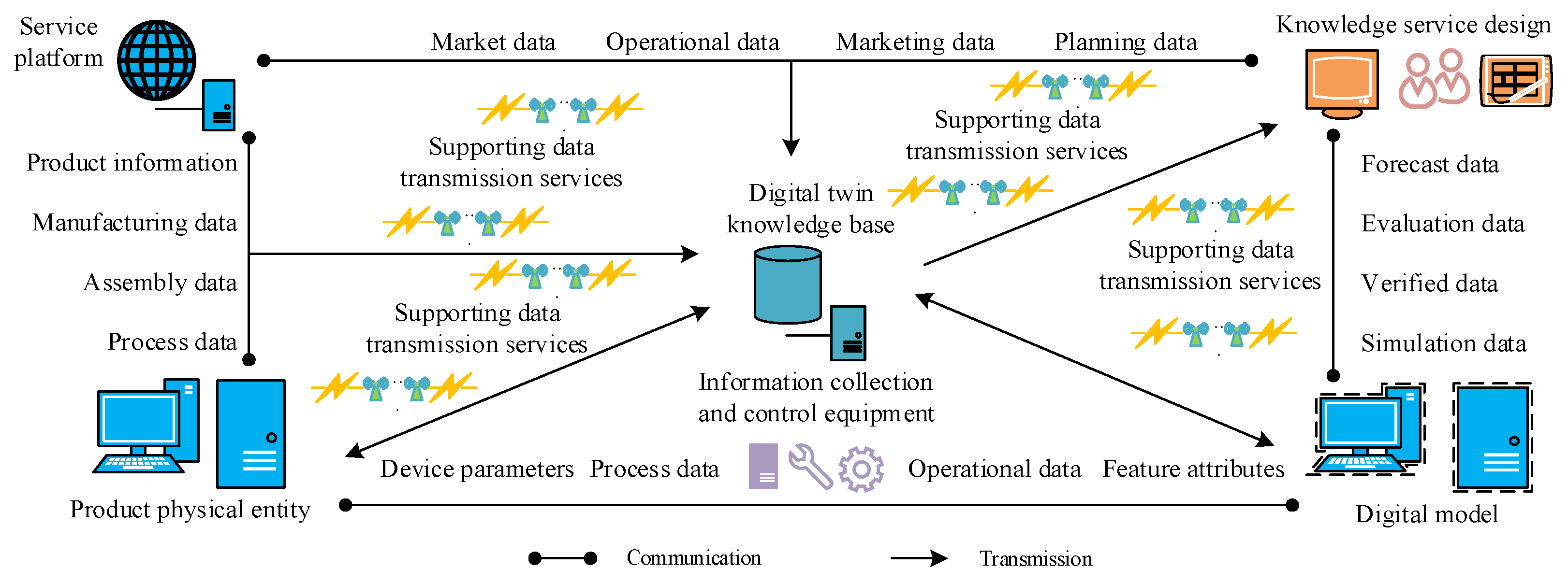
Digital twin is the virtual representation of physical objects, such as various manufacturing resources [21]. It has been extensively applied in industrial designs to avail comparatively tangible design. Specifically, Tao et al. [22,23] proposed a 5D model of digital twinning for information and physics system integration, information physics data fusion, and virtual–real bidirectional connection and interaction. Wu et al. [24] proposed a conceptual modeling method for intelligent vehicles based on 5D digital twin model and created a conceptual intelligent vehicle design. To continuously improve products design model and physical product, 3D experience platform based on DT was built for user interactive feedback information [25]. To collect and execute big data for system optimization and reconfiguration, a remanufacturing collaboration model was combined with communication ability and a fine perception control function using DT [26]. DT with ontology was applied to capture the diversity and quantity of data in a complex engineering system [27]. DTs have also been used for product innovation and redesign [28,29]. Inspired by these studies, some enterprises wish to build their own digital twin knowledge base for information relating to their existing products. The information is then used in design process of new products. A conceptual model for establishing a digital twin knowledge base is shown in Figure 3.
From Figure 3, establishment of a digital twin knowledge base mainly relies on existing digital twin technology. The product service platform records product information, manufacturing data, assembly data and other relevant data. At the same time, the product service platform can also collect product market data, operational data, etc., and aggregate various data information into a data twin knowledge base through supporting data transmission services. Information collection and control equipment can collect device parameters and operational data of the product physical entity, and establish an information channel between physical prototype and its digital model. This information can also be aggregated into digital twin knowledge base. When serving product design, digital twin knowledge base can output collected simulation data and forecast data to assist designers in designing new products. Similarly, the design process and design information of new products can also be stored in digital twin knowledge base for subsequent recall. The establishment of a digital twin knowledge base can enable enterprises to form a closed loop from product design to product application, and greatly enhance the sustainable competitiveness of enterprise products.
The digital twin knowledge base of a product can be mainly divided into three parts: the product model base, product data base and product knowledge base [30,31,32,33]. Schematic for digital twin knowledge base is shown in Figure 4.
Product model base:
Product model base is mainly used to input and store the product’s structural information (2D, 3D, etc.) with a specified retrieval path.
The process of applying product model base is as follows:
(1)
Create a geometric model of product digital twin.
(2)
Construct a static size of the virtual space entity using data of existing physical static components. Sensors installed in the entity can provide real-time update data of dynamic components in the entity.
(3)
Integrate environmental constraints into the simulation platform and upload and save entity data through the transport layer (ZigBee, WiFi, Ethernet, etc.).
When data in the model base are required, the data can be called through AutoCAD, SolidWorks, and other software to directly complete abstract modeling in the early design stage of the new product.
Product data base:
Product data base processes design information data generated in the design process, entity operation data generated by the monitoring system in the manufacturing process, and data in the maintenance stage, so as to streamline design information.
The main process of applying product data base is as follows:
(1)
Corresponding data are transmitted to a data conversion unit through the transmission layer, and the required data are filtered to reduce the data processing volume, and thus improve running speed.
(2)
By establishing an index, data information is transmitted to a corresponding database storage unit and the information is classified and stored to facilitate subsequent calls.
To speed up the retrieval of required product information, calling the data in the database can be facilitated through the software LabVIEW. Storage of information in the product data base can ensure that various types of product information are readily available, information distortion is minimal, and there is continuous accumulation for subsequent knowledge expression and calculation.
Product knowledge base:
Product knowledge base comprises the learning, sorting, and practical application of information to serve as reference for designers. It includes an auxiliary learning model and a knowledge reasoning model.
In an auxiliary learning model, data are learned and analyzed and algorithm is used to train data samples to realize mapping of module resources and knowledge.
In a knowledge reasoning model, through semantic analysis and knowledge management, combined with the product module resources obtained in the auxiliary learning model, existing product functions are screened and matched so as to quickly determine similar functions of the descendant system.
Effective knowledge management has become an important measure for manufacturing enterprises to shorten the design cycles of new products and gain market competitiveness. A knowledge base via digital twin for an enterprise integrates and streamline complex and random design information. Thus, the information can be manageable and traceable as a ready reference for new design. It allows for comprehension of processing, fusion, and invocation of design information. In this way, it can reduce workload of designers and improve the efficiency and quality of product design. More details and the specific use process of the digital twin knowledge base will be presented during exemplification of the currently proposed method in Section 3.2 and Section 4.

2.3. Theory of Inventive Problem Solving

TRIZ is prioritized as a tool for solving problems accurately and quickly. TRIZ contains 39 general engineering parameters, 40 invention principles, and 76 standard solutions. TRIZ tools also include laws of technological evolution, technical conflicts, physical conflicts, material-field analysis, and resource analysis. Increasing the applicability of TRIZ theory is attributed to continuous exploration and advances on the basis of classical TRIZ by many researchers.
Addressing limitations of classical TRIZ, Chinkatham et al. [34] proposed IDM-TRIZ to process broader and more complex problems. Baldussu et al. [35] suggested an improved process of describing natural solutions in an engineering way. A method was also proposed accordingly to describe technology using natural information as a source of inspiration by studying problems in the problem-solving process of TRIZ and biomimicry. To tackle the TRIZ problem of lacking a dominant mode in industrial organizations, Borgianni et al. [36] evaluated influence of TRIZ learning (tools and logic) on individual talent from four aspects: test definition, assessment criteria, comparisons, and related criteria. Frillici et al. [37] identified the most suitable TRIZ tools for each generally effective step in conceptual design process, improving classical design process by combining it with TRIZ knowledge base. To optimize process of describing conflict in TRIZ problem solving, Rousselot et al. [38] proposed a formal definition of conflict and its potential operation in design of inventions. Yan et al. [39,40] developed an intelligent knowledge management system, IngeniousTRIZ, which availed application of TRIZ models and knowledge at different levels of abstraction. An extended latent semantic analysis model was proposed to detect missing link between TRIZ knowledge sources. Sheu et al. [41] proposed an enhanced version of TRIZ philosophy based on four philosophical pillars of classical TRIZ, bridging gap between basic theory and effective practical application. Wu et al. [24] introduced a digital twin framework in conceptual design phase to guide modeling process. TRIZ functional model was then modified according to this framework to focus on components of the model and their interactions. Components, behaviors, and rules of digital twin model were also systematically expressed. Sauli et al. [42] proposed a design analysis method combining TRIZ and CAD through effective modeling, which helped to solve key problems of satellite loader components in conceptual design stage. Kandukuri et al. [43] developed an Enhanced TRIZ (ETRIZ) matrix that assembled and customized existing remanufacturing and additive manufacturing guidelines. In addition to overcoming design-related conflicts originating from remanufacturing, ETRIZ helps increase use of additive manufacturing in remanufacturing.
With the rapid development of computer technology, researchers have proposed that TRIZ can be combined with computer technology to optimize the innovative design process. As a result, computer-aided innovation (CAI) with TRIZ and ontology as the core is composed of advanced technologies, such as network technology, modern design methodology, semantic processing technology, and graphic interaction.
Many research scholars have conducted research on CAI technical tools. Leon [44] integrated marketing analysis, problems solving, product optimization design, and CAI technology tools to form a new innovation model. Hüsig et al. [45] introduced development stages of CAI technology from perspective of new product development. With support of innovative design and information technology, Hüsig et al. [45] proposed application, classification, potential role, and development trend of CAI technology in new product development process. Cugini et al. [46] proposed integrate CAI optimization and PLM system, optimizing system complementarity to improve product development cycle because conceptual design schemes form CAI technology cannot smoothly export to CAD. Flores et al. [47] summarized current status of CAI technology tools, studied the next development stage of CAI Open CAI 2.0, and detailed impact of CAI technology development on different fields. Zhang et al. [48] and others proposed design process of creating an innovative scheme-forming knowledge-driving structure design.
Thanks to the efforts of a great many researchers, TRIZ theory has been continuously improved and developed towards a more rigorous and intelligent direction. Problems in the design process can be solved well using TRIZ.

3. Framework and Process Model of Multi-Analogy Innovation Design

3.1. Framework of Multi-Analogy Innovation Design

This study proposes a method to improve innovative design feasibility by integrating digital twin and analogy. Combining analogy through DCC, TRIZ, and knowledge base of digital twin, a multi-analogy innovative design framework is constructed, as illustrated in Figure 5.
From Figure 5, the process for implementation of the currently proposed method a consists of the followings:
  • Obtaining a reference source system by analogy for the design target;
  • Constructing a digital system of the reference source system through analogy between knowledge base of digital twin and patent library;
  • Analyzing conditions and environments of source system for specific product functions and digital system;
  • Integrating real and digital systems and solving complexity problems that arise during the integration of multiple specific systems through complexity analogy;
  • Using TRIZ tools to solve problems in the system for design solutions for the target product.

3.2. Process Model of Multi-Analogy Innovation Design

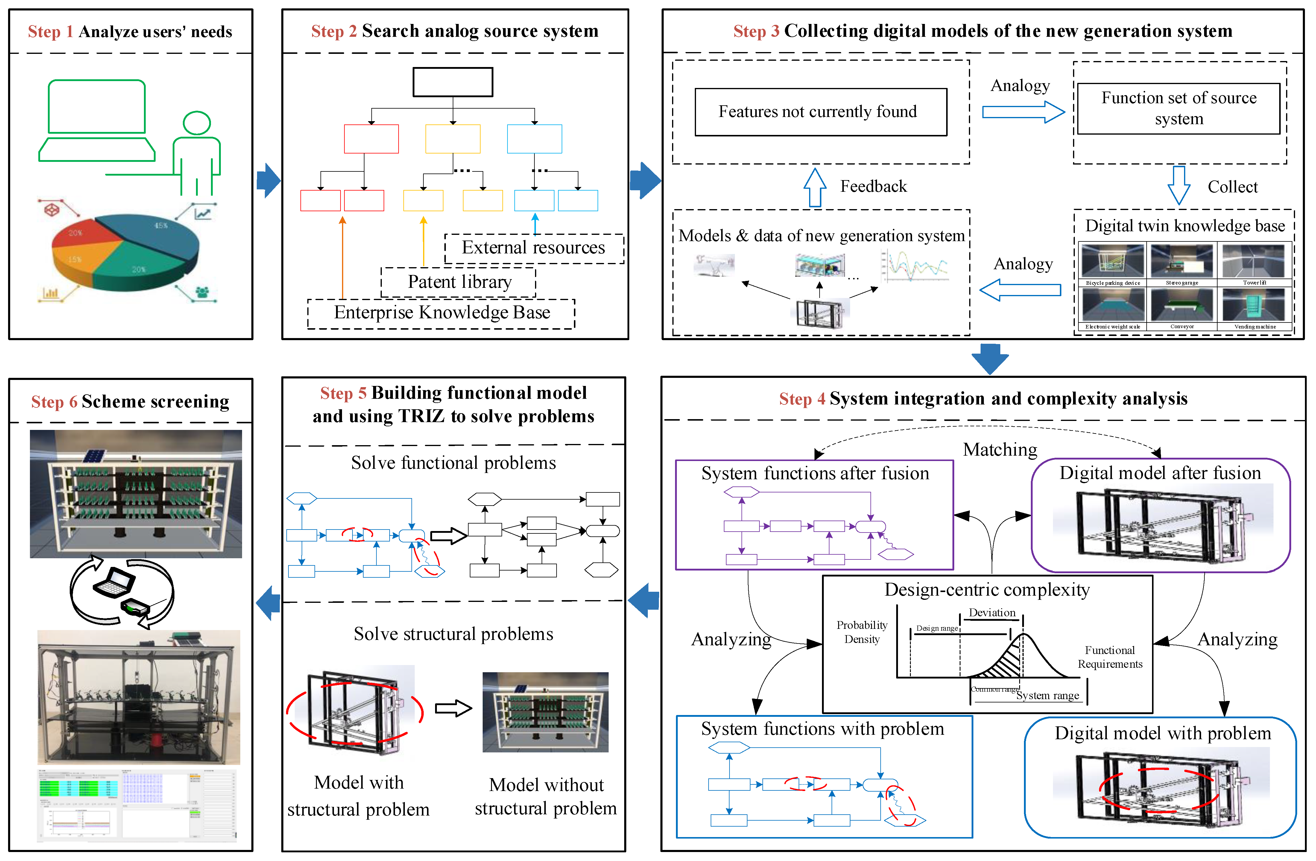
In the multi-analogy innovative design framework, this research conducts an in-depth study of the innovative design process and proposes a multi-analogy innovative design process model based on digital twin. The Main process of the currently proposed M-AID model includes six steps, as shown in Figure 6. The steps are specified as follows.
Step 1: Analyze users’ needs.
The design goal, total function, and constraints of the system are determined based on the design requirements.
Step 2: Analyze product functions, search for analog sources, and derive the analog function source.
(a) Through function decomposition [49], the total function can be analyzed to determine the sub-functions and function units. Usually, Verb (V) + Noun (N) is used to denote a single function. On the other hand, in the process of obtaining the functional principle, a single function is described by Act (A) + Target (T).
Execution object (EO) A can be obtained by acquiring functional principles. A complete functional principle can be formulated as
f = { E O , A , T }
By similarity analysis among E O , A and T , it yields
f = { E O , A , T } { E O s i m i l a r , A s i m i l a r , T s i m i l a r } = f s i m i l a r  
(b) By identifying similar functions f s i m i l a r i in the existing knowledge base according to the similarity-of-the-function principle from the total function to the function unit, function set F I can then be constituted:
F I = i = 1 n f s i m i l a r i  
where f s i m i l a r i = { E O s i m i l a r i , A s i m i l a r i , T s i m i l a r i } i = 1 , 2 , n .
(c) The unfound functions are abstracted and retrieved in the patent database to obtain similar functions f s i m i l a r j to construct function set F J :
F J = j = 1 m f s i m i l a r j  
where f s i m i l a r j = { E O s i m i l a r j , A s i m i l a r j , T s i m i l a r j } j = 1 , 2 , m .
(d) Functional requirements and external resources are analyzed to identify missed manufacturing sources and the super-system in existing functional sets. This bridges manufacturing system and super-system to determine function f s i m i l a r k , which constitutes function set F K :
F K = k = 1 t f s i m i l a r k  
where f s i m i l a r k = { E O s i m i l a r k , A s i m i l a r k , T s i m i l a r k } k = 1 , 2 , t .
Due to similarity of the searching process, the functions obtained can largely meet the requirements of the new generation system, that is, all functions are valid to constitute set F N , thus
F N F I + F J + F K = i = 1 n f s i m i l a r i + j = 1 m f s i m i l a r j + k = 1 t f s i m i l a r k  
Step 3: Collect digital models of the new generation system.
According to the results of Step 2, the process calls the knowledge base of the digital twin and retrieves the corresponding digital system after the retrieval model is formed according to the functional principle. The retrieval process is shown in Figure 7. Source system should exhibit functions that are most similar to total function of target system, its function set F 1 are retrieved from library. Gap between target system and source system, i.e., function set f 1 , is specified. Process then retrieves source system similar to f 1 to construct F 2 and searches gap between F 2 and f 1 to specify f 2 until all analog source systems are explored. It is desirable that all similar functions and their corresponding systems in source database are identified. For instance if some functions cannot be found due to insufficiency of the database, all the similar functions should be searched
After locating a digital model similar to the source system in the knowledge base of the digital twin, the geometric model of the target system can be built as shown in Figure 8. The target system is contrived and displayed virtually/digitally to replicate the physical entities. The model is subsequently modified according to requirements for feasible applications based on the actual data of the original digital twin.
Step 4: Perform system integration and complexity analysis.
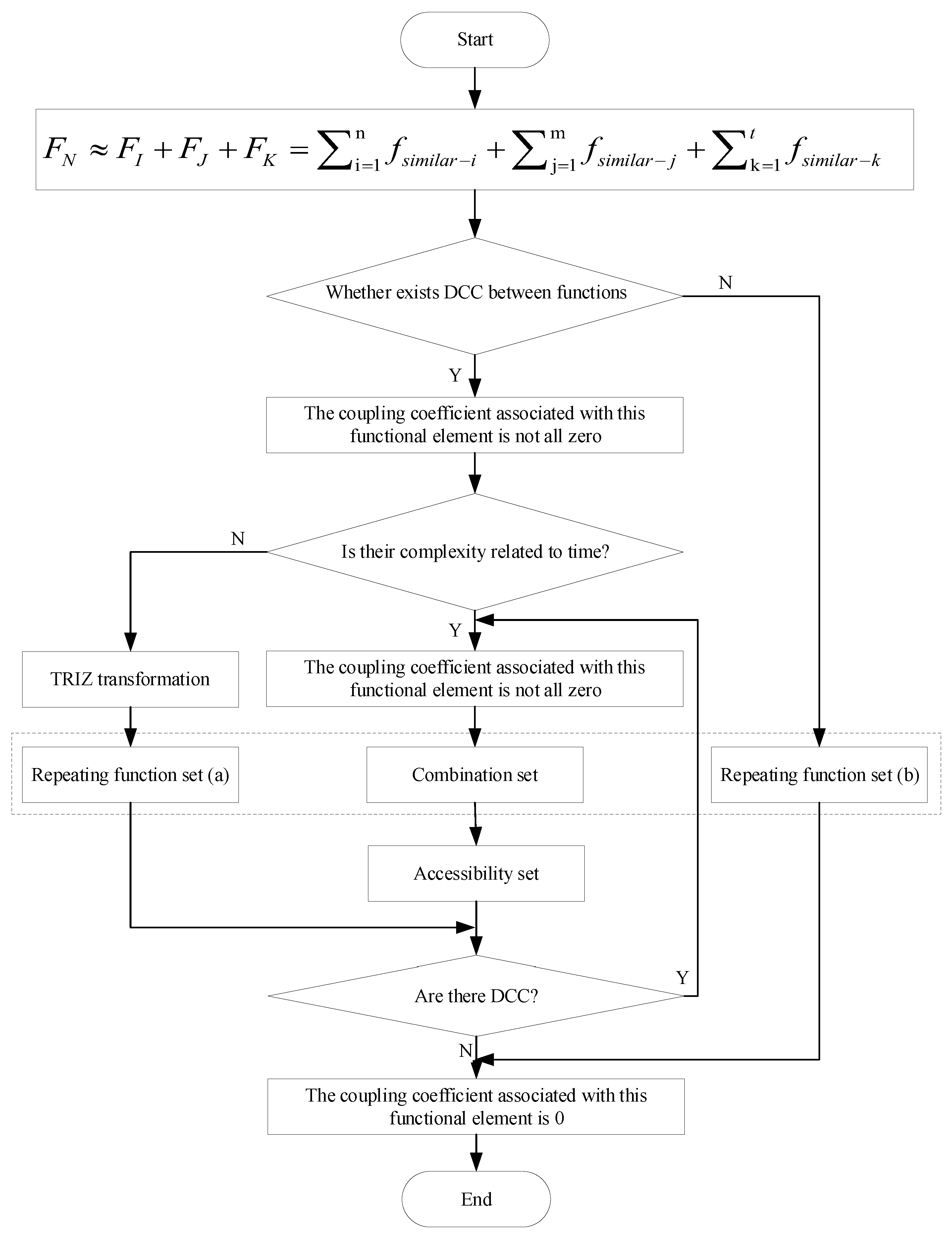
All functions of the new product F N are composed of function sets F I , F J and F K . However, F N is not a simple linear addition of these function sets. Both interactions between new and old functions should be considered. Accordingly, Equation (6) is reformulated as follows,
F N F I + F J + F K = i = 1 n f s i m i l a r i + j = 1 m f s i m i l a r j + k = 1 t f s i m i l a r k  
+ i = 1 n k = 1 t ρ i k f s i m i l a r i f s i m i l a r k + j = 1 m k = 1 t ρ j k f s i m i l a r j f s i m i l a r k
where ρ i j , ρ i k , and ρ j k are coupling coefficients between f s i m i l a r i and f s i m i l a r j , f s i m i l a r i and f s i m i l a r k , f s i m i l a r j and f s i m i l a r k , respectively.
These couplings among functions lead to system complexity. When integrating the digital model of a new system, it is necessary to consider the complexity characteristics of nonlinearity, strong coupling, time-varying characteristics, and openness among different functions and different modules [50,51]. Therefore, during system fusion, DCC theory can be combined with complexity analogy in Figure 5 to analyze the function complexity of the system for decomposition, and thus to reduce complexity. The specific process is shown in Figure 9.
Step 5: Build functional model and use TRIZ to solve problems.
This step combines function and structure information with the functional principle obtained in Step 2 and expresses it graphically to construct a functional model of the new system, as shown in Figure 10.
According to TRIZ analogy in Figure 5, functional or structural problems that still appear in the system after fusion are analyzed by converting them into TRIZ problems to formulate the target system.
Step 6: Perform scheme screening.
Since multiple sources of analogy will be implemented in the analogy process and the derived target system can also be multiple, duplicate solutions of the target system are then screened. A criterion for evaluation of the plan from the perspective of device complexity and economy is established to identify the best scheme. Five evaluation criteria are: Complexity (complexity of scheme), Effect (realization effect of function), Consumption resource (resource consumption of system during use), Economy (project construction cost), Constraint condition (constraints in implementation of scheme), as shown in Table 1. Final evaluation value S of the scheme is calculated by formula in Table 1 according to evaluation result.

4. Case Study

A solar panel dust removal system was designed by applying the currently proposed method. Solar panels convert sunlight into electricity. However, dust accumulation on the solar panel surface during service reduces the conversion efficiency of the panel by 30% to 40% and even negates service life of solar panel. Areas with sufficient light energy feature climate characteristics of a dry climate (thus, are dusty), low precipitation, and a tendency to accumulate dust on solar panels. Therefore, it is required to design a dust removal system for solar panels. The currently proposed method was applied in the design of a solar panel dust removal system. The six steps for the design are specified as follows.
Step 1: Evaluate the specific requirement situations. For example, in desert areas at high altitudes, the problem of dust accumulation on the surface of solar panels under perennial operation is prominent, reducing the working efficiency of the solar panels and shortening their service life.
Considering the cost of manual cleaning, difficulty in operating large-scale cleaning equipment, and shortage of water resources, there is an urgent need for an efficient dust removal device for solar panels.
Step 2: Obtain the analogy function sources of the dust removal system for the solar panel.
(a) Functional decomposition of overall function is shown in Figure 11a.
(b) A resource data base is formulated to identify a similar system to the solar tracking power generation system. Execution objects are A s i m i l a r , T s i m i l a r , and E O s i m i l a r according to acquisition principle of functions in Table 2.
(c) Since no dust removal analogy source can be found in the existing knowledge base, “dust removal” is generalized and second analogy is carried out with regard to the patent base. Four similar systems are identified, i.e., car wipers, high-pressure water guns, hair dryers, and vacuum cleaners, as shown in Figure 11b. Amongst them, function sets F 2 , F 3 , and F 4 have dust removal as the main function. Main function of set F 5 is not dust removal. Instead, it belongs to a system with similar functions. Combination of F 1 and F 2 forms a preliminary function set A; combination of F 1 and F 3 forms a preliminary function set B; and unification of F 1 , F 4 , and F 5 forms a preliminary function set C, as shown in Figure 11a, in which, f i j ( i = 1,2,3…; j = 1,2,3…) is the code of the j-th sub-function in the i-th function set.
(d) Missing products and super-systems in three the preliminary schemes (gray shading in Table A1, Table A2 and Table A3 in Appendix A) as well as interactions between them and system components are then identified. The functions contained in the three systems are F N A , F N B , and F N C , as shown in Appendix A.
Step 3: According to the functional principle obtained in Step 2, acquire the corresponding digital twin model by analogy in the knowledge base of digital twin, as shown in Figure 11c.
Knowledge base of solar energy alignment system is identified as reference scheme. Digital twin model and information on high-pressure water cannon and vacuum cleaner are purchased from two design agencies and then imported into existing knowledge base. Digital model and information on wiper were obtained from team of vehicles of a university. Digital twin model of hair dryer was adapted from a certified hair dryer.
The search tool is shown in Figure 12a. The search interface can select search mode in part ①; in part ②, function number can be selected and entry of function description is entered; part ③ is control button; parts ④ and ⑤ are interface after function search, where a similar system can be selected; part ⑥ is function description interface of selected source system, in which green font has similar function as input in part ②; and part ⑦ is display interface of the system; button of link below the picture can be linked to knowledge base of digital twin corresponding to the system. Using this retrieval software, a similar system and its digital system can be acquired according to the original functional understanding.
Its knowledge base of digital twin is shown in Figure 12b. The establishment process is as follows:
Step a: Use SolidWorks to build a model of system.
Step b: Import the established model into the c4d modeling software, and output the .obj file after rendering the model.
Step c: Import the .obj file into ThingJS’s unique modeling software (DDM) to further build the system model, and name each twin module to facilitate the use of subsequent twin models.
Step d: Export ThingJS file, and then import the file into the ThingJS online development platform to establish a digital twin model. The data of each module are transmitted using the Websocket protocol. It is worth mentioning that the data are collected and transmitted in real time.
Due to software permission restrictions, the data collected by the sensor cannot be directly transferred into the digital twin model. Therefore, this research uses LABVIEW to collect and process data and input the processed data into the digital model to complete the interaction between the entity and the digital model. At the same time, because of the limitations in the technology, only part of the data in the prototype can be twinned.
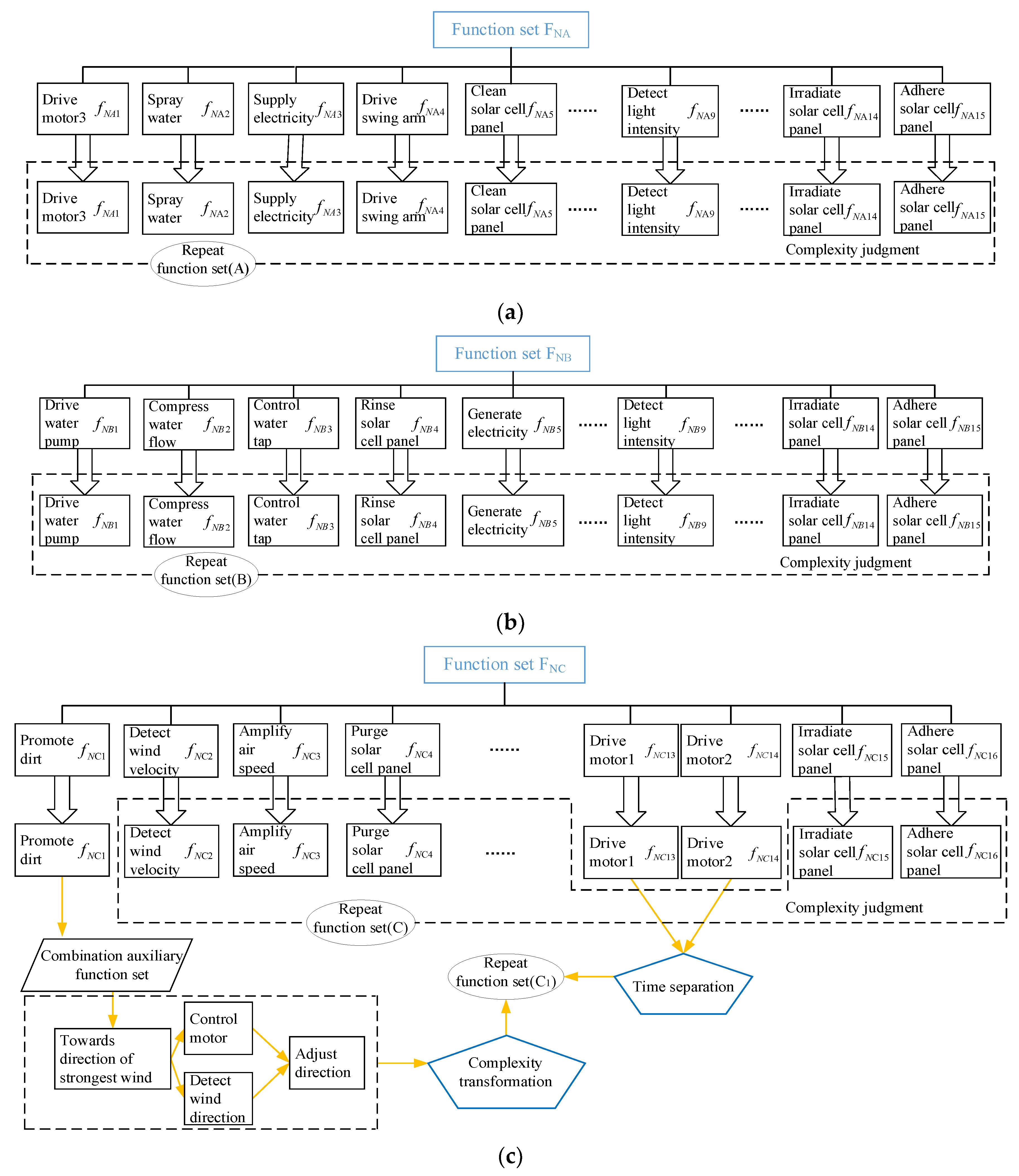
Step 4: Evaluate the complexity of the design process of the dust removal system for solar panel according to the probability of realization of each function. In Schemes A and B, the degree of coupling among functional elements is straightforward to specify as the complexity of the design process is 0, which is an effective and complete function set that can satisfy design requirements. Functions in Scheme A are classified as duplicate function sets A ( F N A ), as shown in Figure 13a, in which, f N A i (i = 1,2,3…) is the code of each sub-function in scheme A, and functions in Scheme B are classified as duplicate function sets B ( F N B ) are shown in Figure 13b, in which, f N B i (i = 1,2,3…) is the code of each sub-function in scheme B.
However, the coupling relationship among functional elements in Scheme C is complex. According to DCC theory, the complexity of functional elements in a natural wind driver should be evaluated one by one, as shown in Figure 13c, and complexity of the system is reduced through complexity transformation.
In the design process, the rotation of panel is complicated. There is complexity between the two functions of (1) rotating battery panel and (2) cleaning dust by following wind, which cannot fulfill design requirement. Analysis shows that conflict between these two functions is independent of time, that is, realization probability of rotating battery panel is not time-bounded. After complexity transformation (the principle of time separation), it is classified as a repetitive function set (C1). The system is set to generate electricity by solar energy during the day and to remove dust at night to circumvent mutual interference.
Analysis of the entire system and super-system impact shows that a wind speed of less than 5.5 m/s is not strong enough to blow away dust, which complicates dust removal function. If not removed in time, dust will accumulate and the system complexity will increase with time. Therefore, the realization probability of dust removal is related to time and it is classified as a combination set. It is necessary to add auxiliary function sets, for example, wind direction detection. Specifically, wind direction should be identified to orientate the air-amplifying device accordingly, so that wind can enter the device. Wind speed can be then amplified to achieve a better dust removal effect, and thus realize the dust removal function.
Step 5: Use the TRIZ tool to solve problems.
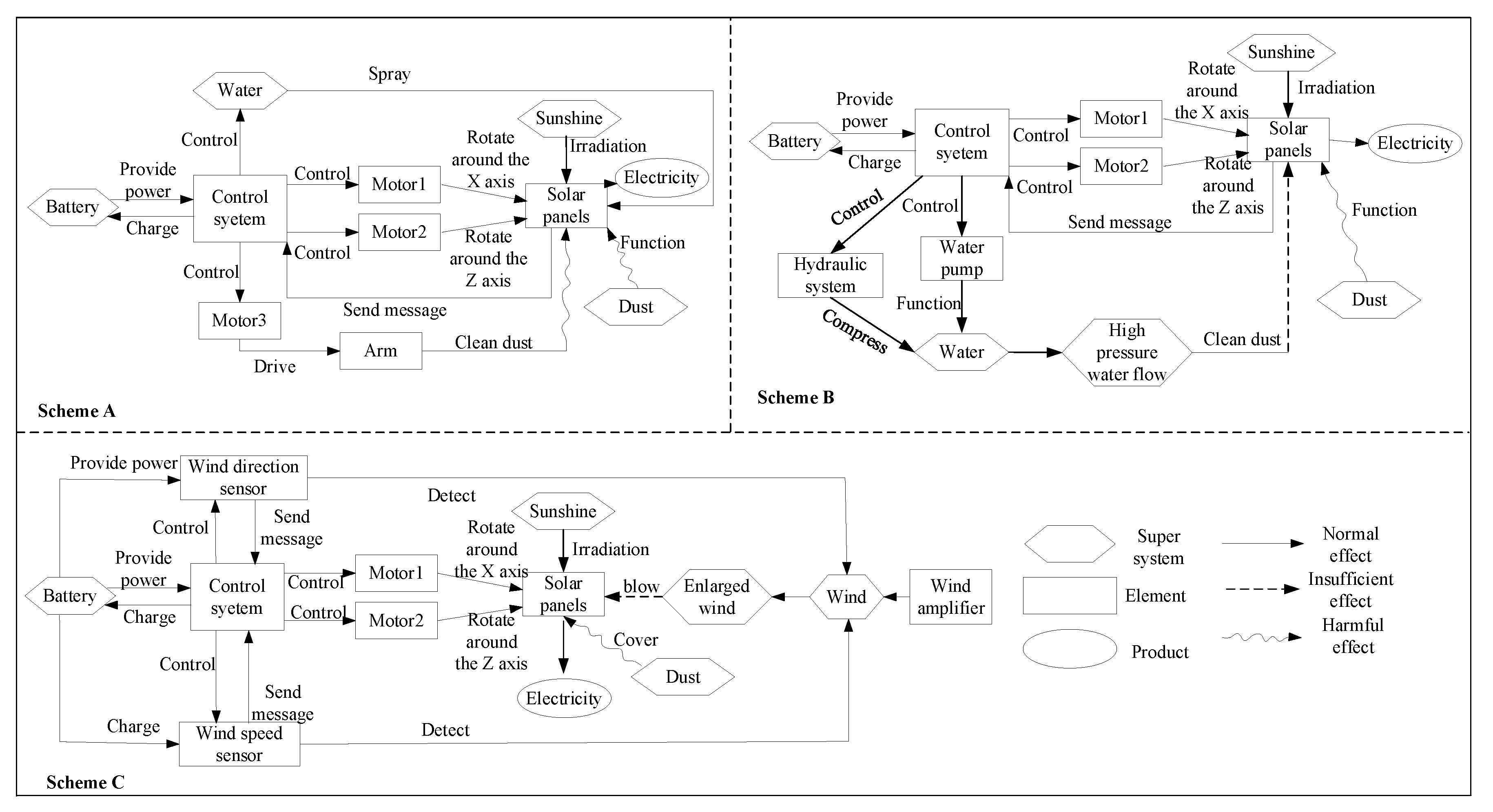
After addressing the solution of the system complexity, the functional model and digital model are established. Three schemes of functional models of a dust removal system for a solar panel are shown in Figure 14, and digital models of preliminary schemes are shown in Appendix B.
As can be seen in Figure 14, there are still some problems in the initially proposed scheme. In order to make the system complete, these problems need to be analyzed and solved. The problems existing in the system can be analyzed and solved by TRIZ. The analysis and solution process of the system is shown in Table 3.
Step 6: Perform scheme screening.
After deciding the final scheme of the system, schemes of the dust removal system for solar panel are evaluated by specified criteria. Results are presented in Table 4. Scheme C the natural wind dust removal system for solar panels, was identified to be the best one.
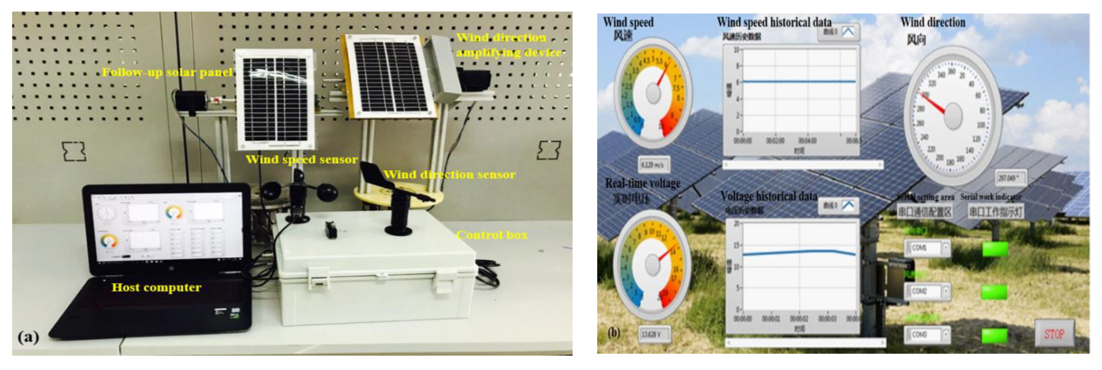
Based on selected optimal design, its physical prototype was built as shown in Figure 15a. Its setup in a server–main display interface is shown in Figure 15b.
According to the wind force comparison table (Table A4, shown in Appendix C), in theory, only when wind speed reaches 5.5 m/s or above, can wind remove dust. However, the in actual test, the effect of dust removal is observable only when wind speed is higher than 9 m/s.
Wind dust removal device obtained by previous analogy to a Hair dryer is an air amplification unit based on the Venturi effect and Funnel effect. The operation information is obtained from knowledge base of digital twin, and ratio of its entry and exit cross-sectional areas resulting in a magnification of the wind force is less than 2:1 (the actual data obtained by the digital twin). If the system is designed according to this ratio, only when the natural wind speed reaches a sufficiently high value, can dust removal structure achieves predetermined effect, which obviously cannot meet design requirements. Considering that average wind speed in operating environment of the device is 3.5 m/s, ratio of inlet and outlet of air amplification unit is modified to be 3:1 by adjusting the structure. In this way, theoretically, when air inlet speed of air amplification unit is 3.5 m/s (forward-blowing speed), outlet speed can reach nearly 10 m/s. Wind speed at outlet can blow dust away from solar panel surface, achieving desired effect.
This dust removal device is a tapered structure, and effect of increased wind speed is achieved by area difference between inlet and outlet. When heat exchange between gas and inner wall of the structure is ignored, flow of gas can be analyzed as an adiabatic flow process:
d A / A = v 2 / c 2 1 d v / v
where v is flow rate of fluid in the device; c stands for sound velocity, and A represents section area of the device.
When flow velocity is less than sound velocity, flow velocity increases with decrease in device cross-sectional area. According to constant flow Q, inlet and outlet flow of the device can be expressed as
Q = A 1 v 1 = A 2 v 2
where A1 and A2 are cross-sectional areas of inlet and outlet, respectively, v1 and v2 are flow rates of inlet and outlet fluids, respectively.
That is, flow velocity through inlet and outlet of the device is inversely proportional to cross-sectional size. The degree of wind speed amplification can be achieved by adjusting the cross-sectional size of inlet and outlet
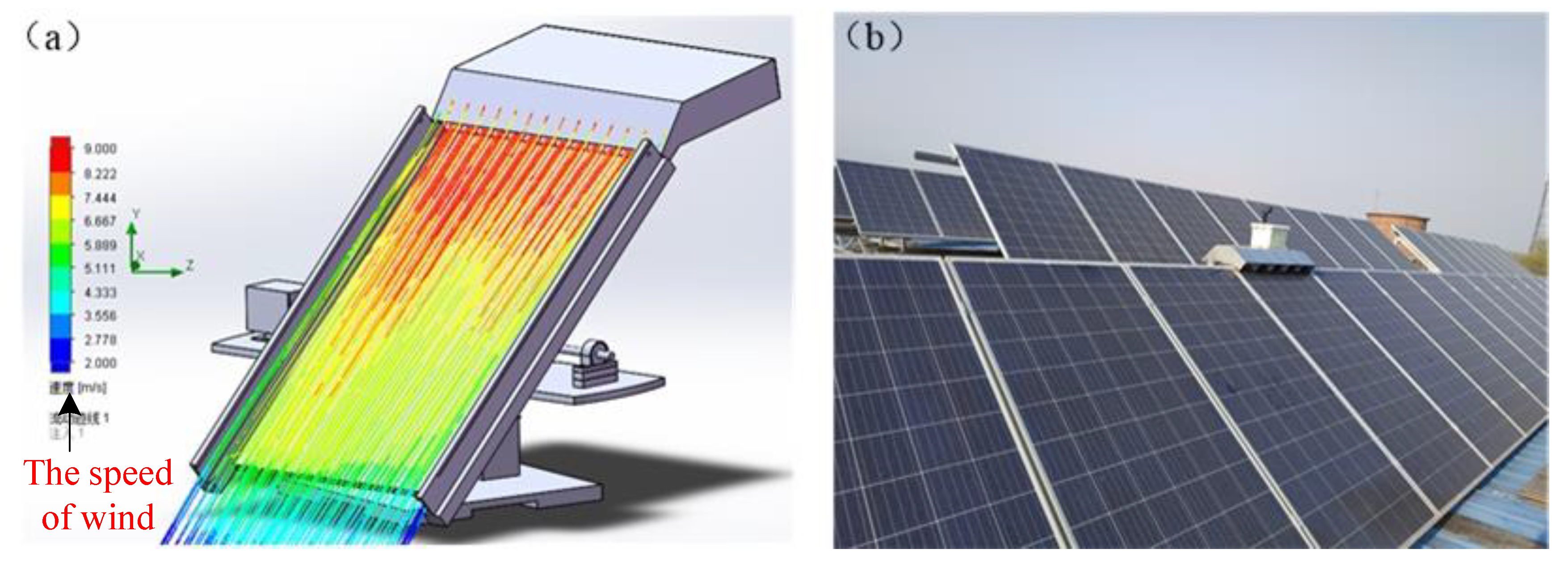
Based on the above data and analysis, improvements were made to the air amplification device obtained from the hair dryer. Combined with the specific structure of the solar panel (the actual data obtained by the digital twin) the air amplification device is designed. The improved system is simulated, and a prototype is made to verify the effect of the scheme through actual experiments. Simulation results and prototype test process are shown in Figure 16.
The actual data obtained through the digital twin plays an important role in the design of the scheme. The actual data guarantees the reliability in the process from conceptual design to actual prototype design. Similarly, designing on the basis of actual data ensures the feasibility of the scheme, which can be confirmed by the approximation of the actual experimental results and the expected results.

5. Evaluation of the Currently Proposed Method and Solution

To verify the feasibility of the scheme and the effectiveness of the proposed method, a performance test of the scheme was conducted as follows.

5.1. Discussion of Design Solution

Performance test of the design is shown in Appendix D. A Comparison of the hourly power output of the solar panels before and after dust removal was used in the experiment. Experimental results are shown in Appendix E, and data analysis is shown in Figure 17.
From field test results, this device has a significant dust removal effect. Sixteen sets of data were collected through experimental tests, as shown in Appendix E, where V0 is the output voltage of solar panels without dust, V1 is the output voltage of solar panels after dust accumulation, and V2 is output voltage of solar panels after dust removal.
According to the change in the output voltages of the solar panel, the efficiency of dust removal is calculated by
e f f i c i e n c y = ( V 2 V 1 ) / ( V 1 V 0 )
From the results in Figure 17, after using the natural wind dust removal system for solar panels, their power generation efficiency was increased by about 56% compared to that of the original system, which proves the effectiveness of current scheme.
According to the demand for a dust removal system for solar panels in Step 1 of Section 4, seven comparative aspects of dust removal system were comprehensively analyzed. As shown in Table 5, five of these aspects were applicable scenarios, energy for dust removal, degree of automation, effect of dust removal, and cost. Current design results and existing systems were compared in terms of these five aspects.
Comparison in Table 5 shows that manual dust removal and water gun dust removal require a large amount of water, making them unsuitable for dry areas in view of shortage of water in these areas and incurring an unreasonably high cost. Waterless robot dedusting does not require water, but it is not suitable for large-area solar panel dedusting due to high cost of manufacturing, maintenance, or leasing. Therefore, the current design of natural wind dust removal system should be the most suitable under the given conditions.
Solution obtained by the currently proposed M-AID process model mainly uses natural wind, and there is almost no other energy consumption except for that in detection and control system, which substantially improves cost-effectiveness for users of solar energy. According to different usage scenarios, current design has applied for four invention patents, two of which have been authorized. Advantages and rationality of the case confirm effectiveness of currently proposed method.

5.2. Discussion of Method

Compared with existing analogy-based design studies [14,15,16,17,18,20,52], the currently proposed M-AID process model features more rigorous and tangible implementation steps. It starts from prototype of source systems and combines retrieval of patent library. In addition, rather than just integrating conceptual schemes to form new conceptual schemes, it retrieves knowledge base of digital twin for the obtained schemes to yield more objective and feasible design. The currently proposed model applies real design information, manufacturing production data, and maintenance information into process from primitive scheme to detailed design of the system to obtain more realistic schemes. In process of prototype modeling and testing, real data from the digital twin library also makes verification results of the case more realistic.
It can be stated that the currently proposed M-AID process model is an effective innovative design method. Rather than only comparing the function, structure, and principle of the system for a conceptual design, it combines digital twin technology and analogy-based design for integrating model data and operating data of the original system into schemes. The practical applicability of the scheme is substantially improved. From methodology point of view, the currently proposed M-AID process model makes full use of existing resource and patent data base to render design process as credible as or even more credible than other prevailing scientific methods, such as DCC and TRIZ.

6. Conclusions

So far as the current design case of a dust removal system is concerned, the currently proposed method has been proved feasible. In this study, relevant practical process information of existing manufacturing, assembly, and testing systems is used in the design process to enhance design scheme feasibility. Introduction of real information also reduces the number of iterations from conceptual scheme to final scheme in design process, and thus improves the efficiency of innovative design process. In addition, by combining DT, DCC, and TRIZ, the currently proposed multi-level analogy concept exhibits as new pathway to enrich analogy design.
The M-AID process model will facilitate the design and development of mechanical systems and product-service systems. Through multi-analogy, the conceptual scheme and model of the target system can be obtained, and the feasibility of the scheme can be improved through model data and operational data contained in the digital twin system. The currently proposed method improves design efficiency, shortens design cycle, and saves resources for product innovation process. On this basis, enterprises committed to developing mechanical and product-service systems can improve the sustainability of their product design by establishing their own digital twin knowledge base and corresponding analogy pathway.
Although this research strives to propose new design methods, the limitations are also obvious. When different companies build their own knowledge bases of digital twins, the software and concepts they use may vary substantially. The amount of data obtained through the digital twin is substantial which may reduce scalability and flexibility. Our further research will consider how to enable designers to better select appropriate data. This study proposes a product digital twin model using the analogy method for similar functions and structures; however, it does not consider in detail constraints by environments or other conditions, which may lead to a lack of proficiency in the schemes obtained by analogy. Therefore, our further research will also consider a more detailed analogy process to match digital twin technology with an intelligent retrieval method.

Author Contributions

Conceptualization by Q.P. and Z.N.; data curation by Z.Z.; formal analysis by G.C. and P.Z.; methodology by Z.N. and P.Z.; resources by G.C. and P.Z.; software by Z.N. and Z.Z.; writing—original draft by Z.N.; writing—review and editing by G.C., P.Z. and Q.P. All authors have read and agreed to the published version of the manuscript.

Funding

This work is supported by the National Natural Science Foundation of China (Grant No. 51975181), the National Innovation Method Work Special Project (Grant No. 2019IM020200), National Innovation Method Work Special Project (Grant No. 2020IM020500), and the Hebei Province Innovative Ability Uplifting Project (Grant No. 21567657H).

Institutional Review Board Statement

Not applicable.

Informed Consent Statement

Not applicable.

Data Availability Statement

The data presented in the current study are available from the authors on reasonable request.

Conflicts of Interest

There is no conflict of interest in the research presented in this manuscript, and the manuscript has been approved by all authors for publication.

Abbreviations

M-AIDMulti-analogy innovation design
DCCDesign-centric complexity
TRIZTheory of Inventive Problem Solving
DTDigital twin
ABDAnalogy-based design
S-B-FStructure–Behavior–Function
VVerb
NNoun
AAct
TTarget
EOExecution object
Fi, i = 1, 2, 3,…Function
Ai, i = 1, 2, 3,…Act
Ti, i = 1, 2, 3,…Target
EOi, i = 1, 2, 3,…Execution object
vi, i = 1, 2, 3,…Flow rate of the fluid in the device

Appendix A

Table A1. Function and principle of F N A .
F N A V N E O sim i l a r A sim i l a r T sim i l a r
1DriveMotor 3Control systemDriveMotor 3
2SprayWaterControl systemSprayWater
3SupplyElectrical energyCellProvide powerControl system
4DriveSwing armMechanical structureDriveSwing arm
5CleanSolar cell panelSwing armCleanSolar cell panel
6GenerateElectricitySolar cell panelGenerateElectricity
7DepotElectricityCellDepotElectricity
8SupplyElectricityCellProvide powerLight sensor
9DetectLight intensityLight sensorDetectSunlight
10Rotate horizontallySolar cell panelHorizontal motorRotate horizontallySolar cell panel
11Rotate verticallySolar cell panelVertical motorRotate verticallySolar cell panel
12DriveMotor 1Control systemDriveMotor 1
13DriveMotor 2Control systemDriveMotor 2
14IrradiateSolar cell panelSunlightIrradiateSolar cell panel
15AdhereSolar cell panelDirtAdhereSolar cell panel
Table A2. Function and principle of F N B .
F N B V N E O sim i l a r A sim i l a r T sim i l a r
1DriveWater pumpControl systemDriveWater pump
2CompressWater flowControl systemCompressWater flow
3ControlWater tapControl systemControlWater tap
4RinseSolar cell panelCompressed waterRinseSolar cell panel
5GenerateElectricitySolar cell panelGenerateElectricity
6DepotElectricityCellDepotElectricity
7SupplyElectricitySellProvide powerLight sensor
8SupplyElectricityCellProvide powerControl system
9DetectLight intensityLight sensorDetectSunlight
10Rotate horizontallySolar cell panelHorizontal motorRotate horizontallySolar cell panel
11Rotate verticallySolar cell panelVertical motorRotate verticallySolar cell panel
12DriveMotor1Control systemDriveMotor1
13DriveMotor2Control systemDriveMotor2
14IrradiateSolar cell panelSunlightIrradiateSolar cell panel
15AdhereSolar cell paneldirtAdhereSolar cell panel
Table A3. Function and principle of F N C .
F N C V N E O sim i l a r A sim i l a r T sim i l a r
1PromoteDirtAirPromoteDirt
2DetectWind velocityWind speed sensorDetectWind velocity
3AmplifyAir speedAir amplifierAmplifyAir
4PurgeSolar cell panelAmplified windPurgeSolar cell panel
5DetectDirection of windDirection sensorDetectDirection of wind
6GenerateElectricitySolar cell panelGenerateElectricity
7DepotElectricityCellDepotElectricity
8SupplyElectricityCellProvide powerLight sensor
9SupplyElectricityCellProvide powerControl system
10DetectLight intensityLight sensorDetectSunlight
11Rotate horizontallySolar cell panelVertical motorRotate horizontallySolar cell panel
12Rotate verticallySolar cell panelHorizontal motorRotate verticallySolar cell panel
13DriveMotor 1Control systemDriveMotor 1
14DriveMotor 2Control systemDriveMotor 2
15IrradiateSolar cell panelSunlightIrradiateSolar cell panel
16AdhereSolar cell panelDirtAdhereSolar cell panel

Appendix B

Figure A1. Model of scheme A (a) Model of scheme B (b) Model of scheme C (c).
Machines 10 00652 g0a1

Appendix C

Table A4. Wind speed comparison table.
Level Wind Speed (m/s)(km/h)Phenomenon on the GroundHeight of the Waves (m)
00.0–0.2<1Smoke moves straight up.0.0
10.3–1.51–5Smoke is blown away by the wind.0.1
21.6–3.36–11Leaves rustle loudly.0.2
33.4–5.412–19Branches swing.0.6
45.5–7.920–28Dust, paper, and sand are blown up by the wind.1.0
58.0–10.729–38Small trees sway.2.0
610.8–13.839–49It is difficult to lift umbrellas.3.0
713.9–17.150–61It is difficult to walk.4.0
817.2–20.762–74Tree branches are blown away.5.5
920.8–24.475–88Tiles are blown away.7.0
1024.5–28.489–102Trees are uprooted.9.0
1128.5–32.6103–117Major damage is inflicted.11.5

Appendix D

Figure A2. Snapshots of experiment: (a) overall setting and (b) close-in view.
Machines 10 00652 g0a2

Appendix E

Table A5. Experimental data of dust removal effect.
NumberV0 (V)V1 (V)V2 (V)η%
112.4411.1311.7648.09
211.7611.1311.4550.79
312.0411.3511.7152.17
412.2110.9511.5950.79
511.8311.2911.5751.85
612.1411.0811.6553.77
712.1111.1211.6755.56
811.8311.1311.5255.71
912.1111.0411.6153.27
1012.0811.1511.6856.99
1112.2411.1411.7757.27
1212.1610.9411.6659.02
1311.9410.2111.2660.69
1412.3210.6211.7465.88
1512.0610.8411.6566.39
1612.0311.3111.7358.33

References

  1. Liu, X.; Luo, L.; Chen, L.; Li, J. Research on Bio-inspired Design Based on C-K Theory for Product Innovation. J. Mech. Eng. 2020, 56, 207. [Google Scholar]
  2. Fu, K.; Chan, J.; Cagan, J.; Kotovsky, K.; Schunn, C.; Wood, K. The meaning of “near” and “far”: The impact of structuring design databases and the effect of distance of analogy on design output. J. Mech. Design 2013, 135, 021007. [Google Scholar] [CrossRef] [Green Version]
  3. Christensen, B.T.; Schunn, C.D. The relationship of analogical distance to analogical function and preinventive structure: The case of engineering design. Mem. Cogn. 2007, 35, 29–38. [Google Scholar] [CrossRef] [Green Version]
  4. Qian, L.; Gero, J.S. Function–behavior–structure paths and their role in analogy-based design. AI EDAM 1996, 10, 289–312. [Google Scholar] [CrossRef]
  5. Liu, X.; Tan, R.; Yao, L. Application research on integrated process model for the conceptual design of product innovation. Chin. J. Mech. Eng. 2008, 44, 154–162. [Google Scholar] [CrossRef]
  6. Goel, A.K.; Bhatta, S.R. Use of design patterns in analogy-based design. Adv. Eng. Inform. 2004, 18, 85–94. [Google Scholar] [CrossRef]
  7. Zhang, P.; Nie, Z.; Dong, Y.; Zhang, Z.; Yu, F.; Tan, R. Smart concept design based on recessive inheritance in complex electromechanical system. Adv. Eng. Inform. 2019, 43, 101010. [Google Scholar] [CrossRef]
  8. Glaessgen, E.; Stargel, D. The digital twin paradigm for future NASA and US Air Force vehicles. In Proceedings of the 53rd AIAA/ASME/ASCE/AHS/ASC Structures, Structural Dynamics and Materials Conference 20th AIAA/ASME/AHS Adaptive Structures Conference 14th AIAA, Honolulu, HI, USA, 23–26 April 2012; p. 1818. [Google Scholar]
  9. Wagner, C.; Grothoff, J.; Epple, U.; Drath, R.; Malakuti, S.; Gruner, S.; Hoffmeister, M.; Zimermann, P. The role of the Industry 4.0 asset administration shell and the digital twin during the life cycle of a plant. In Proceedings of the 2017 22nd IEEE International Conference on Emerging Technologies and Factory Automation (ETFA), Limassol, Cyprus, 12–15 September 2017; pp. 1–8. [Google Scholar] [CrossRef]
  10. Grieves, M.; Vickers, J. Digital Twin: Mitigating Unpredictable, Undesirable Emergent Behavior in Complex Systems. In Transdisciplinary Perspectives on Complex Systems; Springer: Cham, Switzerland, 2017; pp. 85–113. [Google Scholar]
  11. Tao, F.; Sui, F.; Liu, A.; Qi, Q.; Zhang, M.; Song, B.; Guo, Z.; Lu, S.C.-Y.; Nee, A.Y.C. Digital twin-driven product design framework. Int. J. Prod. Res. 2019, 57, 3935–3953. [Google Scholar] [CrossRef] [Green Version]
  12. Singh, V.; Willcox, K.E. Engineering Design with Digital Thread. AIAA J. 2018, 56, 4515–4528. [Google Scholar] [CrossRef]
  13. Moyne, J.; Qamsane, Y.; Balta, E.C.; Kovalenko, I.; Faris, J.; Barton, K.; Tilbury, D.M. A Requirements Driven Digital Twin Framework: Specification and Opportunities. IEEE Access 2020, 8, 107781–107801. [Google Scholar] [CrossRef]
  14. Jia, L.; Peng, Q.; Tan, R.; Zhu, X. Analogical stimuli retrieval approach based on R-SBF ontology model. J. Eng. Des. 2019, 30, 599–624. [Google Scholar] [CrossRef]
  15. Liu, X.M.; Huang, S.P.; Wang, J.H.; Lin, G. Conceptual design based on TRIZ & function analogy for product innovation. J. Mech. Eng. 2016, 52, 34–42. [Google Scholar]
  16. Dunbar, K.; Baker, L.M. Goals, analogy, and the social constraints of scientific discovery. Behav. Brain Sci. 1994, 17, 538–539. [Google Scholar] [CrossRef]
  17. Tan, R.; Zhang, R.; Liu, F.; Yang, B.-J. Two stages analogy-based conceptual design based on TRIZ. Comput. Integr. Manuf. Syst. 2006, 12, 328. [Google Scholar]
  18. Jia, L.-Z.; Wu, C.-L.; Zhu, X.-H.; Tan, R.-H. Design by Analogy: Achieving More Patentable Ideas from One Creative Design. Chin. J. Mech. Eng. 2018, 31, 37. [Google Scholar] [CrossRef] [Green Version]
  19. Moreno, D.P.; Blessing, L.T.; Yang, M.C.; Hernández, A.A.; Wood, K.L. Overcoming design fixation: Design by analogy studies and nonintuitive findings. Artif. Intell. Eng. Des. Anal. Manuf. 2016, 30, 185–199. [Google Scholar] [CrossRef]
  20. Murphy, J.; Fu, K.; Otto, K.; Yang, M.; Jensen, D.; Wood, K. Function Based Design-by-Analogy: A Functional Vector Approach to Analogical Search. J. Mech. Des. 2014, 136, 101102. [Google Scholar] [CrossRef] [Green Version]
  21. Zhang, H.; Yan, Q.; Wen, Z. Information modeling for cyber-physical production system based on digital twin and AutomationML. Int. J. Adv. Manuf. Technol. 2020, 107, 1927–1945. [Google Scholar] [CrossRef]
  22. Tao, F.; Liu, W.; Liu, J.; Liu, X.; Liu, Q.; Qu, T.; Hu, T.; Zhang, Z.; Xiang, F.; Xu, W.; et al. Digital twin and its potential application exploration. Comput. Integr. Manuf. Syst. 2018, 24, 1–18. [Google Scholar]
  23. Tao, F.; Liu, W.; Zhang, M.; Hu, T.; Qi, Q.; Zhang, H.; Sui, F.; Wang, T.; Xu, H.; Huang, Z.; et al. Five-dimension digital twin model and its ten applications. Comput. Integr. Manuf. Syst. 2019, 25, 1–18. [Google Scholar]
  24. Wu, C.; Zhou, Y.; Pessôa, M.V.P.; Peng, Q.; Tan, R. Conceptual digital twin modeling based on an integrated five-dimensional framework and TRIZ function model. J. Manuf. Syst. 2020, 58, 79–93. [Google Scholar] [CrossRef]
  25. Fourgeau, E.; Gomez, E.; Adli, H.; Fernandes, C.; Hagege, M. System engineering workbench for multi-views systems methodology with 3DEXPERIENCE Platform. The Aircraft Radar Use Case. In Advances in Intelligent Systems and Computing; Springer: Cham, Switzerland, 2016; pp. 269–270. [Google Scholar]
  26. Wang, Y.; Wang, S.; Yang, B.; Zhu, L.; Liu, F. Big data driven Hierarchical Digital Twin Predictive Remanufacturing paradigm: Architecture, control mechanism, application scenario and benefits. J. Clean. Prod. 2019, 248, 119299. [Google Scholar] [CrossRef]
  27. Erkoyuncu, J.A.; del Amo, I.F.; Ariansyah, D.; Bulka, D.; Vrabič, R.; Roy, R. A design framework for adaptive digital twins. CIRP Ann. 2020, 69, 145–148. [Google Scholar] [CrossRef]
  28. Dong, Y.; Tan, R.; Zhang, P.; Peng, Q.; Shao, P. Product redesign using functional backtrack with digital twin. Adv. Eng. Inform. 2021, 49, 101361. [Google Scholar] [CrossRef]
  29. Nie, Z.; Zhang, P.; Wang, F.; Wang, Z. Sustainable innovation pathway for mechanical products by inducing characteristic parameters. Adv. Eng. Inform. 2021, 49, 101349. [Google Scholar] [CrossRef]
  30. Zhang, J.S.; Wang, Q.F.; Zhong, Y.F.; Wan, L. Configuration-oriented product modelling and knowledge management for made-to-order manufacturing enterprises. Int. J. Adv. Manuf. Technol. 2005, 25, 41–52. [Google Scholar]
  31. Lim, K.Y.H.; Zheng, P.; Chen, C.-H.; Huang, L. A digital twin-enhanced system for engineering product family design and optimization. J. Manuf. Syst. 2020, 57, 82–93. [Google Scholar] [CrossRef]
  32. Zhou, G.; Zhang, C.; Li, Z.; Ding, K.; Wang, C. Knowledge-driven digital twin manufacturing cell towards intelligent manufacturing. Int. J. Prod. Res. 2019, 58, 1034–1051. [Google Scholar] [CrossRef]
  33. Xiao, F.; Zhang, W.; Wang, D.; Peng, K.; Qian, F. System architecture and applications for overall design of solid rocket motor based on digital twin. Comput. Integr. Manuf. Syst. 2019, 25, 1405–1418. [Google Scholar]
  34. Chinkatham, T.; Cavallucci, D. Early feasibility evaluation of Solution Concepts in an Inventive Design Method Framework: Approach and support tool. Comput. Ind. 2015, 67, 1–16. [Google Scholar] [CrossRef]
  35. Baldussu, A.; Cascini, G. About Integration Opportunities between TRIZ and Biomimetics for Inventive Design. Procedia. Eng. 2015, 131, 3–13. [Google Scholar] [CrossRef] [Green Version]
  36. Borgianni, Y.; Cascini, G.; Rotini, F. Preliminary Studies on Human Approaches to Inventive Design Tasks with a TRIZ Perspective. Procedia Eng. 2015, 131, 39–49. [Google Scholar] [CrossRef] [Green Version]
  37. Frillici, F.S.; Fiorineschi, L.; Cascini, G. Linking TRIZ to Conceptual Design Engineering Approaches. Procedia Eng. 2015, 131, 1031–1040. [Google Scholar] [CrossRef] [Green Version]
  38. Rousselot, F.; Zanni-Merk, C.; Cavallucci, D. Towards a formal definition of contradiction in inventive design. Comput. Ind. 2012, 63, 231–242. [Google Scholar] [CrossRef]
  39. Yan, W.; Liu, H.; Zanni-Merk, C.; Cavallucci, D. IngeniousTRIZ: An automatic ontology-based system for solving inventive problems. Knowl.-Based Syst. 2015, 75, 52–65. [Google Scholar] [CrossRef]
  40. Yan, W.; Liu, H.; Liu, Y.; Wang, J.; Zanni-Merk, C.; Cavallucci, D.; Yan, X.; Zhang, L. Latent semantic extraction and analysis for TRIZ-based inventive design. Eur. J. Ind. Eng. 2018, 12, 661–681. [Google Scholar] [CrossRef]
  41. Sheu, D.-L.D.; Chiu, M.-C.; Cayard, D. The 7 pillars of TRIZ philosophies. Comput. Ind. Eng. 2020, 146, 106572. [Google Scholar] [CrossRef]
  42. Sauli, S.A.; Ishak, M.R.; Mustapha, F.; Yidris, N.; Hamat, S. Hybridization of TRIZ and CAD-analysis at the conceptual design stage. Int. J. Comput. Integr. Manuf. 2019, 32, 890–899. [Google Scholar] [CrossRef]
  43. Kandukuri, S.; Günay, E.E.; Al-Araidah, O.; Kremer, G.E.O. Inventive solutions for remanufacturing using additive manufacturing: ETRIZ. J. Clean. Prod. 2021, 305, 126992. [Google Scholar] [CrossRef]
  44. Leon, N. The future of computer-aided innovation. Comput. Ind. 2009, 60, 539–550. [Google Scholar] [CrossRef]
  45. Hüsig, S.; Kohn, S. Computer aided innovation—State of the art from a new product development perspective. Comput. Ind. 2009, 60, 551–562. [Google Scholar] [CrossRef] [Green Version]
  46. Cugini, U.; Cascini, G.; Muzzupappa, M.; Nigrelli, V. Integrated Computer-Aided Innovation: The PROSIT approach. Comput. Ind. 2009, 60, 629–641. [Google Scholar] [CrossRef]
  47. Flores, R.L.; Belaud, J.P.; Negny, S.; Le Lann, J.M. Open computer aided innovation to promote innovation in process engineering. Chem. Eng. Res. Des. 2015, 103, 90–107. [Google Scholar] [CrossRef] [Green Version]
  48. Zhang, J.; Tan, R.; Zhang, Z. Research on the integration of product concept design and particular design driven by CAI technology. J. Mech. Eng. 2016, 52, 47–57. [Google Scholar] [CrossRef]
  49. Zhang, H.G. Innovative Design-Systematic Innovation Based on TRIZ; China Machine Press: Beijing, China, 2017; pp. 79–80. [Google Scholar]
  50. Frey, D.D.; Jahangir, E.; Engelhardt, F. Computing the Information Content of Decoupled Designs. Res. Eng. Des. 2000, 12, 90–102. [Google Scholar] [CrossRef]
  51. Suh, N.P. Complexity in engineering. CIRP Ann. 2005, 54, 46–63. [Google Scholar] [CrossRef]
  52. Zhang, P.; Li, X.; Nie, Z.; Yu, F.; Liu, W. A Trimming Design Method Based on Bio-Inspired Design for System Innovation. Appl. Sci. 2021, 11, 4060. [Google Scholar] [CrossRef]
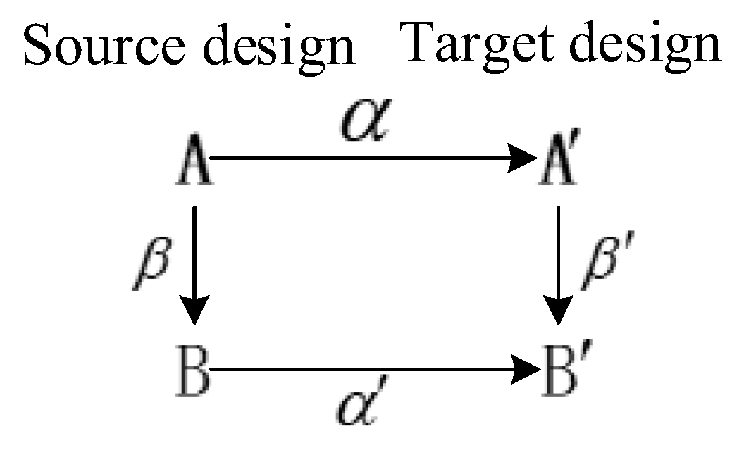
Figure 1. Concept of analogy design [17].
Machines 10 00652 g001
Figure 2. Two-stage analogy conceptual model [17].
Machines 10 00652 g002
Figure 3. Concept for establishing digital twin knowledge base.
Machines 10 00652 g003
Figure 4. Schematic for digital twin knowledge base [30,31,32,33].
Machines 10 00652 g004
Figure 5. Schematic for currently proposed multi-analogy innovative design framework.
Machines 10 00652 g005
Figure 6. Process model of M-AID.
Machines 10 00652 g006
Figure 7. Digital model analogy retrieval process.
Machines 10 00652 g007
Figure 8. Schematic for digital model combination process.
Machines 10 00652 g008
Figure 9. Schematic for digital model combination process.
Machines 10 00652 g009
Figure 10. Construction process of function model.
Machines 10 00652 g010
Figure 11. Functional decomposition and system analogy.
Machines 10 00652 g011
Figure 12. (a) Search interface and (b) digital twin knowledge base.
Machines 10 00652 g012
Figure 13. (a) Analysis of complexity in System A, (b) analysis of complexity in System B, and (c) analysis of complexity in System C.
Machines 10 00652 g013
Figure 14. Function model of schemes.
Machines 10 00652 g014
Figure 15. (a) Natural wind dust removal system for a solar panel. (b) Interface of system.
Machines 10 00652 g015
Figure 16. (a) Simulation in Ansys and (b) experimental prototype.
Machines 10 00652 g016
Figure 17. Analysis of dust removal efficiency.
Machines 10 00652 g017
Table 1. Evaluation criteria for scheme.
Evaluation
Conditions
Complexity 1Effect 2Consumption
Resource 3
Economy 4Constraint
Condition 5
S
Weight w0.100.300.100.250.25 i = 1 5 ω i q i
Value ranges q−1 × n (number of functions)1 to 4
(poor)
−1 × (1 to 4)
(poor)
1 to 4
(poor)
−1 × n
(number of constraints)
5 to 8
(general)
−1 × (5 to 8)
(general)
5 to 8
(general)
9 to 10
(good)
−1 × (9 to 10)
(higher)
9 to 10
(good)
Table 2. Function and principle of similar systems.
I V N A sim i l a r T sim i l a r E O sim i l a r  
11GenerateElectricityGenerateElectricitySolar cell panel
12DepotElectricityDepotElectricityCell
13SupplyElectricityProvide powerLight sensorCell
14SupplyElectricityProvide powerControl systemCell
15MonitorDirectionDetectSunlightLight sensor
16Rotate horizontallyCell panelRotate horizontallySolar cell panelHorizontal motor
17Rotate verticallyCell panelRotate verticallySolar cell panelVertical motor
18DriveMotor1DriveMotor1Control system
19DriveMotor2DriveMotor2Control system
Table 3. Analysis and solution process of the system.
SchemeProblemTRIZ
General Questions
TRIZ
General Solution
TRIZ
Special Solution
Scheme Drawing
AThe goal is to remove as much dust as possible, but too much friction will wear out the surface of the battery panel.Improve
parameter: Loss of
substance
Deterioration parameter:
Object-generated harmful factors
22: Turning harmful into beneficial
30: Flexible shells or thin films
33:
Homogeneity
40: Composite materials
Select 30th invention principle to get specific plan: Change material of brush and improve brushing method to rolling erasing. Machines 10 00652 i001
BTo clean the battery panel, the position of the high-pressure water gun needs to be changed, but this will lead to more complex devices.Improve parameter: Ease of operation
Deterioration parameter: Device complexity
12:
Equipotentiality
17: Another
dimension
26: Copying
32: Color modification
Select the 26th invention principle to get a specific plan: Increase the baffle to change the direction of water flow. Machines 10 00652 i002
CFor the system to use wind energy in the direction where wind energy is the greatest, it cannot be in the direction where light energy is best absorbed.The hope is to face the direction of the strongest light but also to maximize the use of wind energyTaking out-Separation Improve structure so that direction of the wind amplifying device can be adjusted independently. Machines 10 00652 i003
Table 4. Evaluation of schemes.
Evaluation ConditionsWeightScheme AScheme BScheme C
Complexity0.1−15−15−16
Effect0.3785
Consumption resource0.1−4−6−1
Economy0.25467
Constraint condition0.25−2−3−1
S——0.71.051.3
Table 5. Solution comparison.
AspectsManual Dust RemovalHigh Pressure-Water Dust RemovalWaterless Robot Dust RemovalNatural Wind Dust Removal
Applicable sceneSmall or home solar panelsSolar panels in areas with abundant water resourcesSolar panels in rainy or low-rain areasSolar power sites in a windy and less rainy area of the northwest
Energy used for dust removalWaterWaterMechanical energyNatural energy
AutomaticityLowMediumHighHigh
Effect of dust removal Very goodGoodGoodGood
CostHigh labor costHigh costExtremely high costLow cost
Advantages and Disadvantages
AdvantagesVery good dust removal effectGood dust removal effectGood dust removal effect less using waterGood dust removal effect without water
DisadvantagesInvolves the use of cleaning agents, which may cause secondary pollution of the environmentRequires a lot of water resources, resulting in waste of resourcesInvolves high construction cost, high maintenance cost, expensive lease, and high driver cost The effect of dust removal is unstable restricted by wind
Publisher’s Note: MDPI stays neutral with regard to jurisdictional claims in published maps and institutional affiliations.