1. Introduction
In today’s developed world, energy is a cardinal factor for the sustainable development and economic growth of a country [
1], and, in recent years, continuous access to inexpensive and reliable energy has become an essential right for humanity [
2]. However, the rise in energy demand and dependence on fossil fuels has led to energy crises, declining resources, and environmental pollution [
3]. Although optimizing energy systems [
4,
5] and employing energy storage devices [
6] are considered by scholars, the use of renewable energy sources [
7] is one of the most effective solutions to cope with these difficulties. Among renewable energy sources, wind energy is the most common and sustainable type of energy and, currently, the application of this free energy source is being considered more than ever [
8]. Harnessing wind energy and converting it to electrical power is carried out with the aid of wind turbines.
The shape of a wind turbine blade has a substantial role in its performance and should be determined according to the design goal or goals. Compared to the experimental and simulation studies conducted on wind turbine blades, optimization algorithms present more feasible and cost-effective solutions for acquiring blade sections with suitable performance in different scenarios. The enhancements obtained with these algorithms result from their searching strategy. Contrary to the other techniques, these algorithms do not depend on searching and testing the entire possibilities. These algorithms make an effort to acquire the optimal solutions by trying the model performance at each trial by the means of an objective function.
Recently, nature-inspired metaheuristic strategies for solving different optimization problems, especially in computer science and engineering, have rapidly increased. Soni et al. [
9] compared the performance of 12 nature-inspired optimization algorithms, including Bat, Lion, Particle swarm, Water wave, Elephant herding, Optics inspired, Cuckoo search, Flower, Genetic, Differential evolution (DE), Harmony, and Simulated annealing algorithms. They discussed the speed, accuracy, performance, convergence, efficiency, and complexity of these algorithms. Their findings revealed that compared to the other selected algorithms, the differential evolution algorithm presents fast speed and performance, as well as the best accuracy.
Tušar and Filipič [
10] compared the performance of genetic algorithms and differential evolution in solving multi-objective optimization problems. Their results showed that the DE algorithm provides better and more stable solutions than genetic algorithms. Similar results were observed in the research of Lilla et al. [
11].
According to the International Electrotechnical Commission (IEC) 61400-2 [
12], a small horizontal-axis wind turbine has a swept area of less than 200 m
2, which corresponds to a blade radius and a power output of less than 8 m and around 50 kW, respectively. In a further subdivision, small wind turbines (SWTs) are divided into three groups, namely micro, mid, and mini, with output power less than 1, 5, and 50 kW, respectively [
13]. Although large wind turbines have gained significant attention from researchers [
14], SWTs have not received the research interest they deserve. These turbines can be employed to supply electricity for domestic and agricultural purposes, and their application is economically viable [
15]. Unlike large wind turbines which are used in windy areas, these turbines can also be installed in places where there is no potential for continuous high-speed wind [
16].
An important difference between large and SWTs is the lack of pitch controllers in SWTs for reducing costs [
17]. Thus, in these turbines, optimally positioning the blade sections in the wind direction is not possible. This point is significantly important when the SWTs are beginning to rotate from a stationary state, since throughout the startup process, the high angles of attack along the blade, result in the reduction in the lift force and aerodynamic torque, and, consequently, the blade rotates slowly and power generation is delayed [
18].
The time required for the turbine to accelerate from a stationary state to a tip speed ratio of around one is called the startup time (
Ts) [
19]. In addition to achieving the maximum power coefficient (
Cp), which is the main goal in designing wind turbine blades, reducing this time has also been one of the interesting topics for researchers in recent years. In this regard, the optimization of SWT blades has been performed to maximize the
Cp and minimize
Ts [
19]. The results showed that most of the turbine power is obtained from the blade tip part while the root section can facilitate the startup process. By properly distributing the chord length and twist angle in these two parts of the blade, a significant improvement was observed in the
Cp and
Ts of these turbines. Pourrajabian et al. [
20] compared the performance of solid and hollow blades in terms of
Cp and
Ts in an SWT. It was observed that compared to the solid blades, the hollow blades exhibit a higher
Cp and lower
Ts. Rahgozar et al. [
21] studied the influence of linear and non-linear distributions of the twist angle and chord length on the
Cp and
Ts of a small horizontal-axis wind turbine. The results showed that, while the use of non-linear distribution can increase the
Cp in windy areas, with linear distribution the blades have a better
Ts in areas with low wind speeds. Minimizing the aerodynamic noise [
22], mass, and cost [
23] are other goals of designing and optimizing SWT blades that have been studied by researchers.
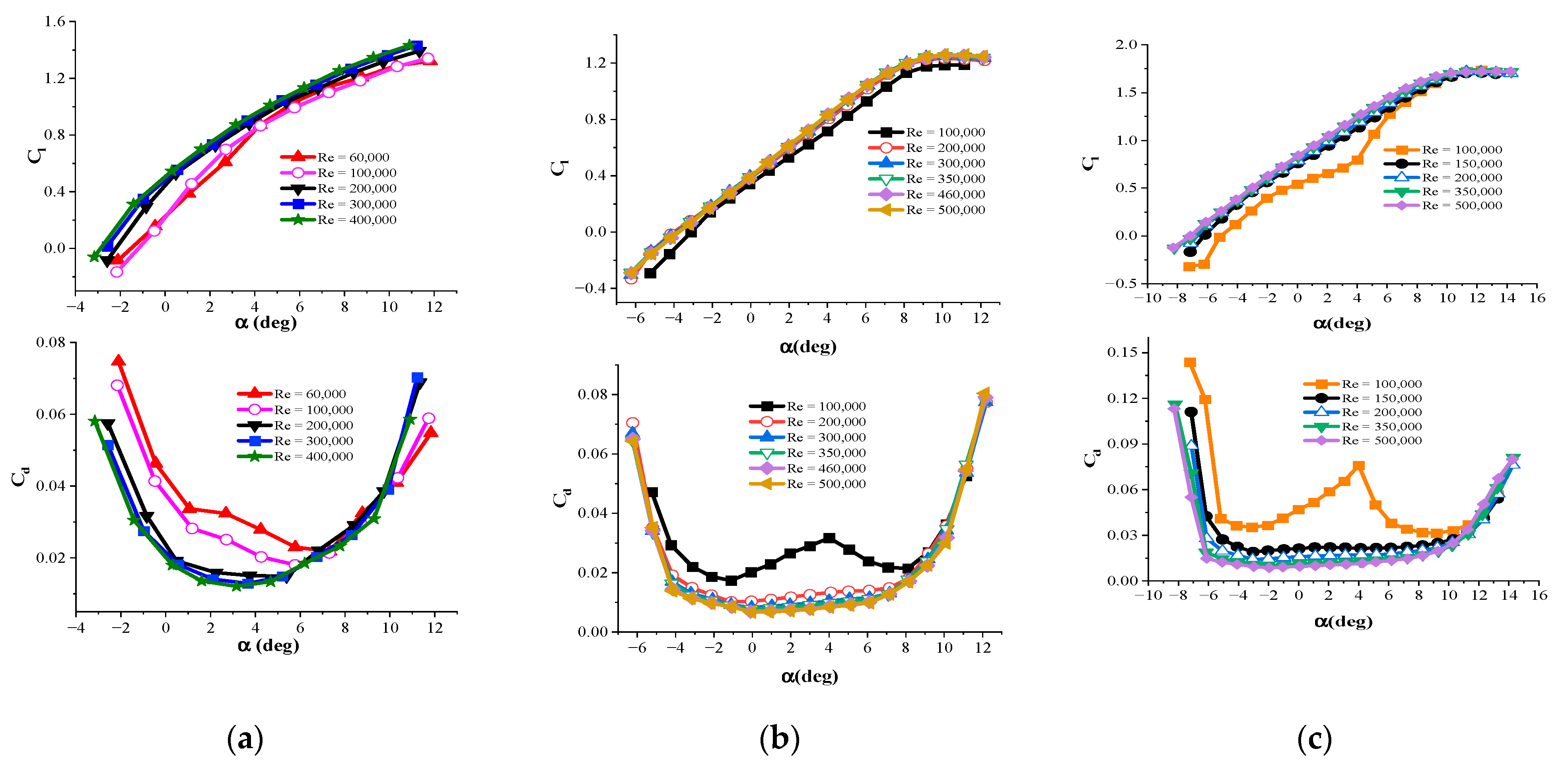
The shape of the airfoil determines the drag and lift coefficients (
Cd and
Cl) and plays a crucial role in the aerodynamic torque generated by the wind turbine blade and its output power. In this regard, researchers have always attempted to use airfoils with high aerodynamic efficiency in blade design [
24].
In general, in large turbines, several airfoils are used in different parts of the blades, each of which has its own task. Thin airfoils with better aerodynamic performance are used at the tip of the blade to provide more power, while thick airfoils are employed at the root of large blades to resist structural stresses [
25]. Unlike large blades, to reduce construction costs as much as possible, the airfoil type of the SWT blades does not change [
26]. The operating Reynolds number (Re) range of SWTs is less than 500,000 [
27]. Therefore, there are not a variety of airfoils to use in these turbines. In this range of Re, the flow on the upper surface of the airfoil is often laminar, so the formation of a laminar separation bubble is possible. To solve this problem and to reduce the adverse pressure gradient on the upper surface of the airfoil, airfoils thinner than the traditional ones are recommended for operation in SWT blades [
28]. Giguere and Selig [
29] designed a group of SG series airfoils (SG6040–SG6043) specifically for use in SWT blades. Studies have shown that increasing the leading edge nose radius, as well as cusping of the trailing edge, improves the aerodynamic performance of thin airfoils, and, in this regard, some airfoils have been proposed specifically for use in SWTs [
30].
Given the importance of the airfoil type used in the blade for the aerodynamic performance of a wind turbine, its proper selection, in terms of the startup process, needs further study. The previous works that were performed in this field are mostly focused on the distribution of chord length and twist angle along the blade, and the effect of the airfoil type used in the blade has not been investigated from the startup viewpoint, which is discussed in the present study. For this purpose, the performance of 10 different airfoils that are specifically designed for SWT blades is examined in terms of the Cp and Ts.
The remainder of this study is organized as follows. The selected airfoils are introduced in
Section 2.
Section 3 presents the numerical techniques that are employed, as well as their validations. The results of the study which include the performance evaluation of the airfoils in windy areas and areas with low wind speed are presented in
Section 4. Finally, the conclusions are discussed in
Section 5.
4. Discussion of Results
Similar to the specified ranges for the design variables (mentioned in
Table 1) and also the value of
Table 2 and
Table 3, n is an input parameter for running the optimization. In multi-objective optimization problems, there is no single answer. In this study, the answers are determined by changing the value of n in the objective function (Equation (1)), which leads to the Pareto front. Here, Pareto front members are the blades whose at least one component of the objective function has a larger
Cp or 1/
Ts value than the other blades. Generally, larger values are considered for n, because the output power is a more important goal than the startup time [
19]. Imposing low weighting factors (
n) causes poor aerodynamic performance of the blade and makes it practically unusable. Selecting the final blade from the Pareto front depends on the wind potential. Although
n = 1 is used in windy areas to achieve the maximum power coefficient,
n = 0.8 is recommended in areas with low wind speeds where the startup performance of turbines is more important [
20,
21].
By considering the input parameters mentioned in
Section 3.3, as well as the explanations provided above, the optimization process was used to evaluate the performance of the selected airfoils, the results, which include
Cp and
Ts, are summarized in
Table 4. It is necessary to explain that the details of the optimization results were also obtained for
n = 0.6, and the tabulated results can be found and compared in
Table A2 of
Appendix C.
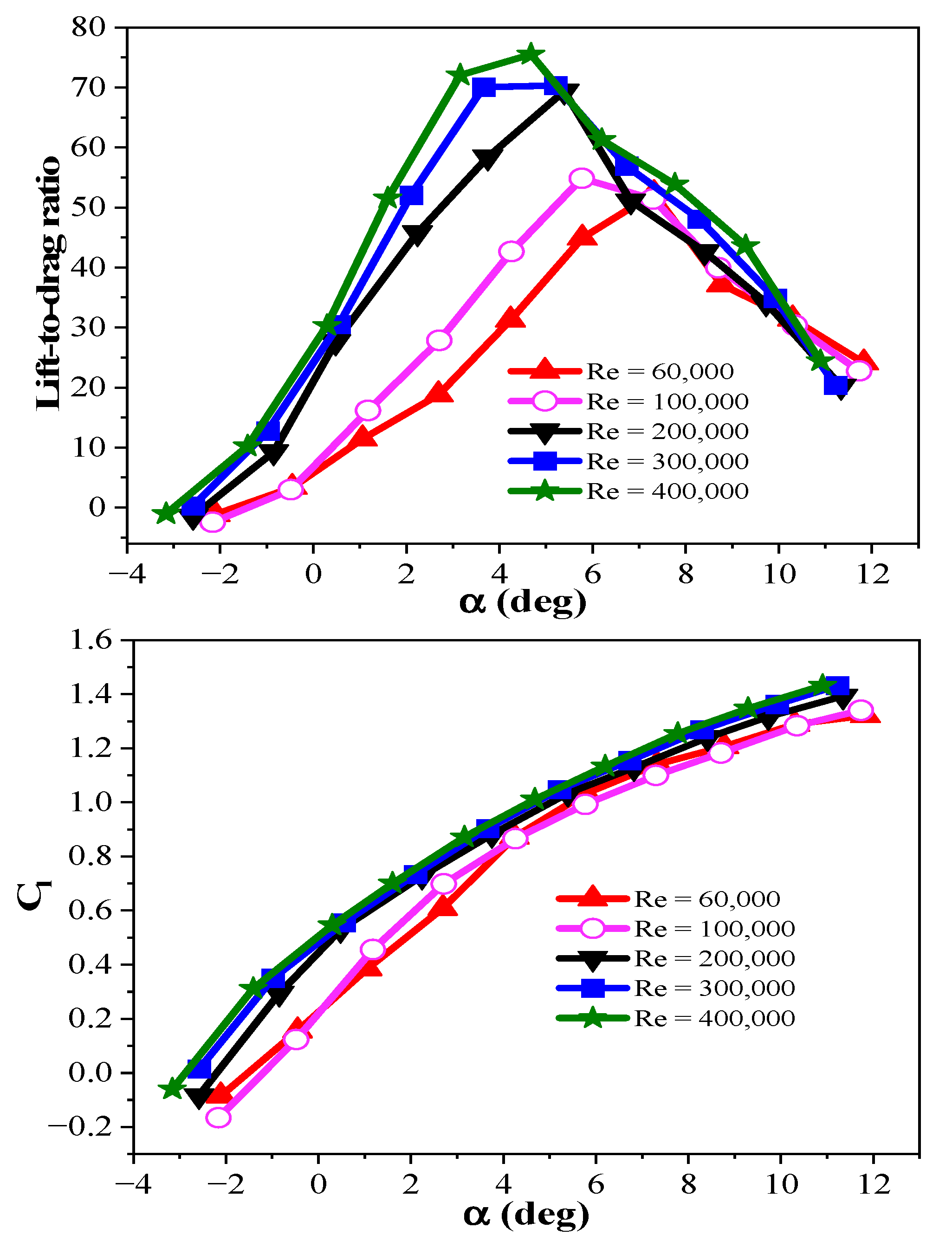
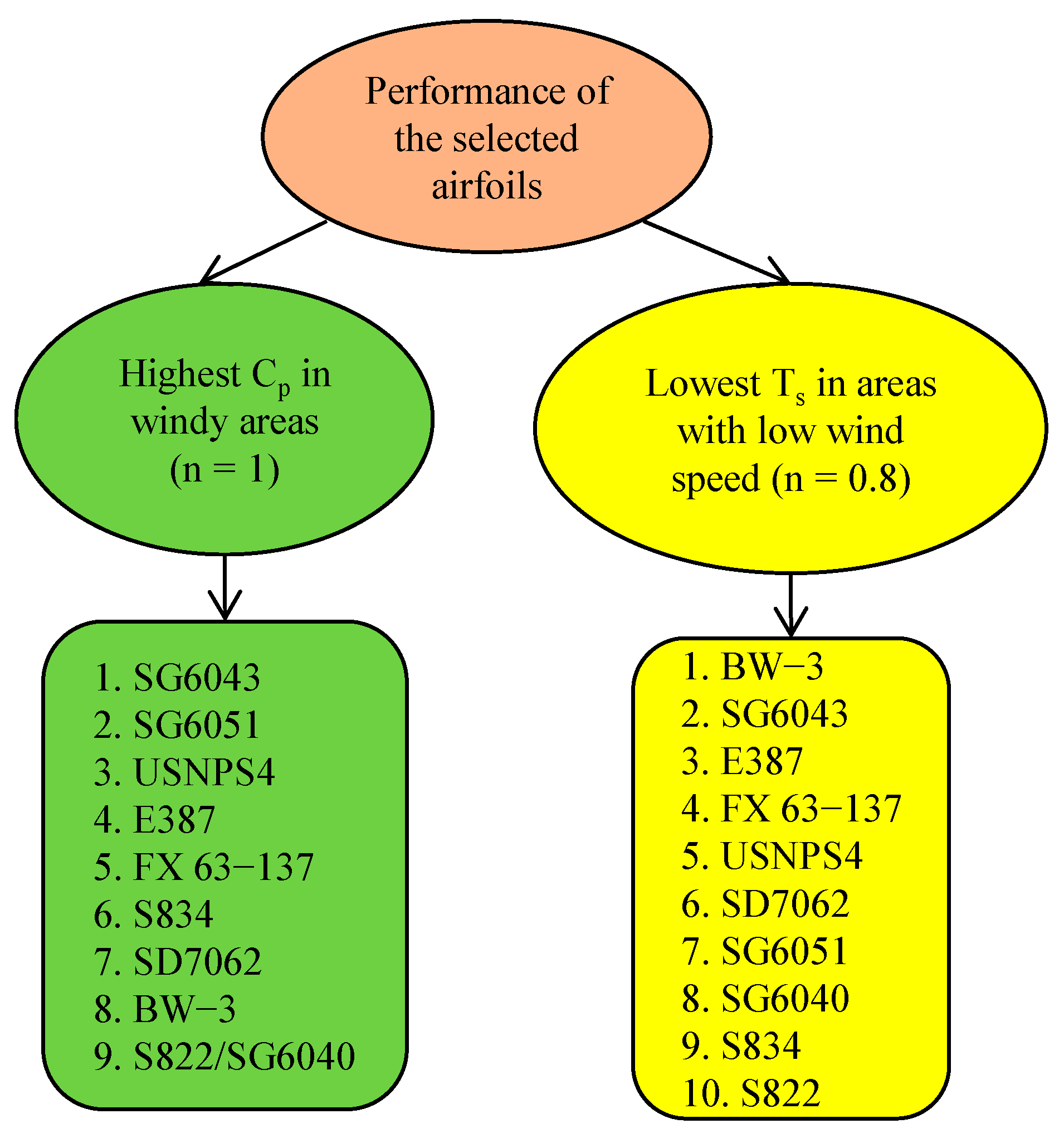
4.1. Investigating the Performance of Airfoils in Windy Areas
In areas with high wind speeds (
n = 1) where
Ts is removed from the objective function, the SG6043 airfoil yields the highest
Cp while the S822 and SG6040 airfoils present the lowest
Cp (see
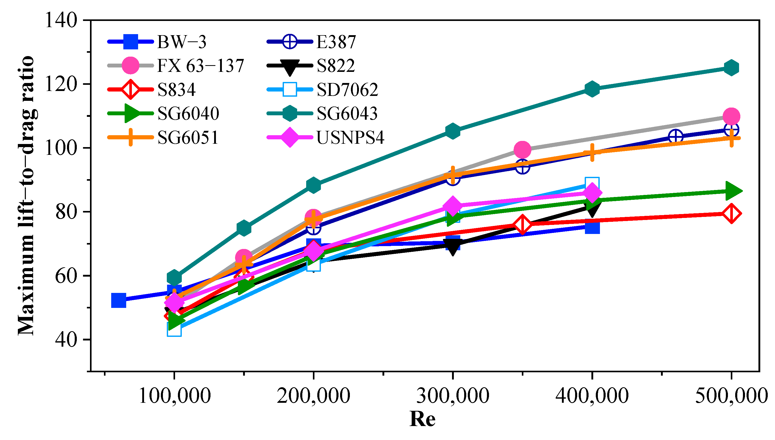
Table 4). The lift-to-drag ratio of airfoils is an important parameter in the efficiency of wind turbine blades.
Figure 10 shows the maximum lift-to-drag ratio of the selected airfoils over a wide range of Re numbers.
It can be observed that, compared to the other airfoils, this value is higher for the SG6043 airfoil. It should be noted that the type of airfoil completely influences the distribution of twist and chord along the blade. Indeed, the optimization algorithm considers the best geometry for the blade based on the aerodynamic coefficients and geometric characteristics of each airfoil.
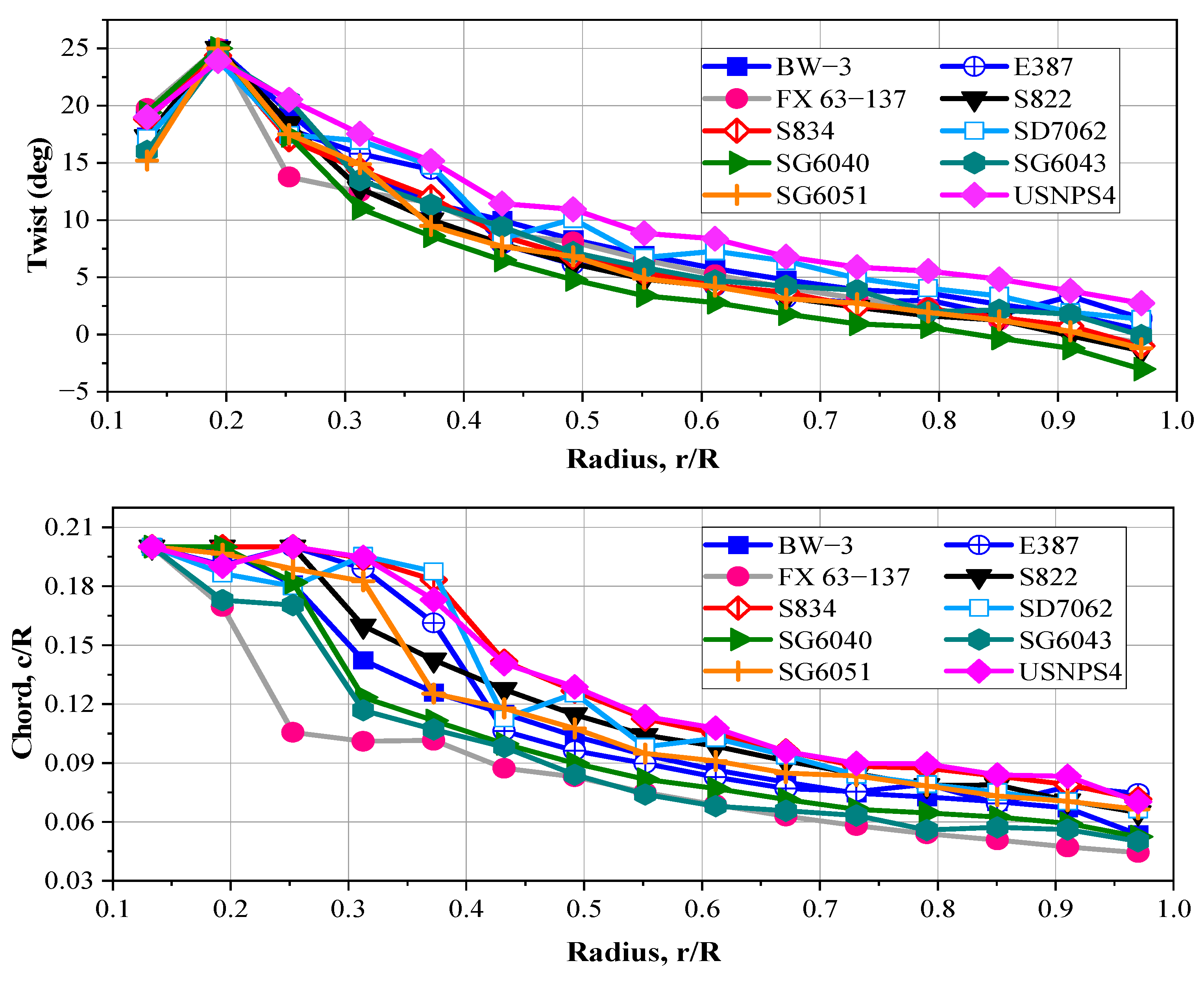
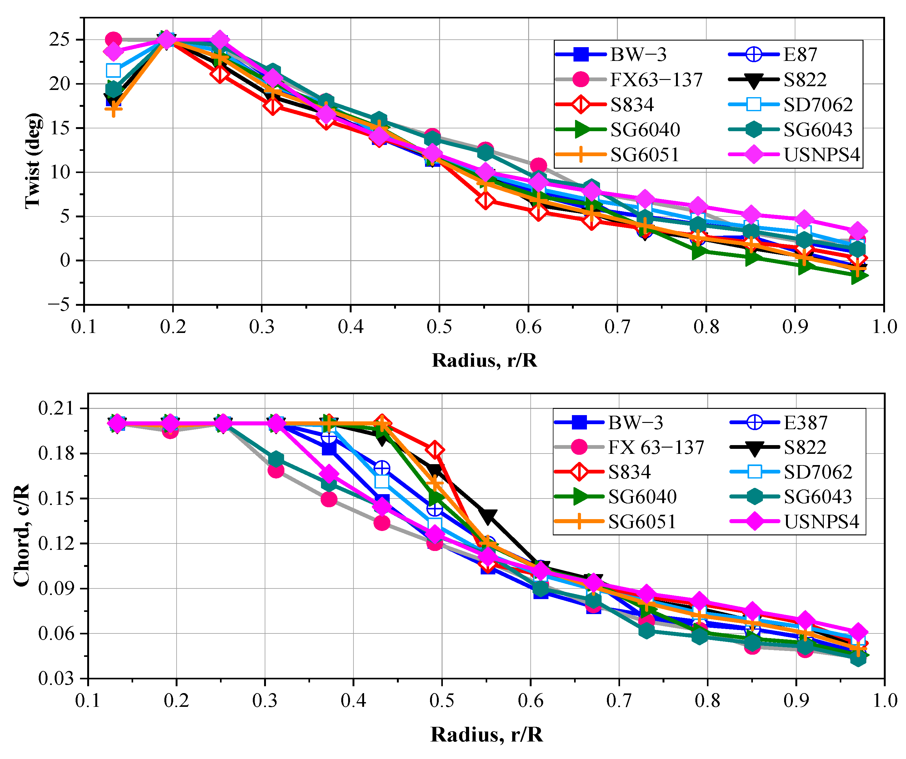
Figure 11 shows the distribution of twist and chord of the selected airfoils for
n = 1.
By focusing on this figure, it can be seen that the values of the chord length for the blade that was fitted with the FX 63-137 airfoil are smaller than the values considered for the other selected airfoils. Due to this, despite the high lift-to-drag ratio of this airfoil (
Figure 10), the
Cp is not so high. Because the smaller chord length leads to a lower Re and, hence, reduces the lift-to-drag ratio. The opposite is true for the USNPS4 airfoil. According to
Figure 10, it can be observed that this airfoil does not have a high lift-to-drag ratio, but the larger chord length values of the blade fitted with this airfoil increase the Re and, consequently, raise the
Cp.
It should be noted that for all selected airfoils, the twist angles and chord lengths are not smooth at the root elements (as seen in
Figure 8). This is due to the low contribution of these elements in the total aerodynamic torque and, hence, the
Cp of the turbine, which makes the optimization algorithm focus on the evolution of the design variables in the middle and tip elements and creates a smoother distribution in these elements. To take a closer look at this point,
Figure 12 illustrates the torque generation distribution along the blade throughout the power generation for the SG6043 and S822 airfoils.
As can be seen, regardless of the airfoil type, a significant portion of the aerodynamic torque is generated by the middle and tip elements of the blade, and the share of the root elements is considerably smaller. It should be noted that the slight decrease in the aerodynamic torque at the tip of the blade is because of considering the blade tip losses in the BEM calculations.
4.2. Investigating the Performance of Airfoils in Areas with Low Wind Speed
In areas with low wind speeds (
n = 0.8), small wind turbines need to react quickly to the wind and start generating power in the shortest possible time. In this regard, Worasinchai et al. [
18] have shown that reducing startup time increases energy capture.
According to
Table 4, the startup performance of the BW-3 airfoil is better than the other selected airfoils. Thus, the turbine that uses this airfoil has the shortest
Ts. The reason is the low inertia of the blades fitted with this airfoil (see
Figure 13).
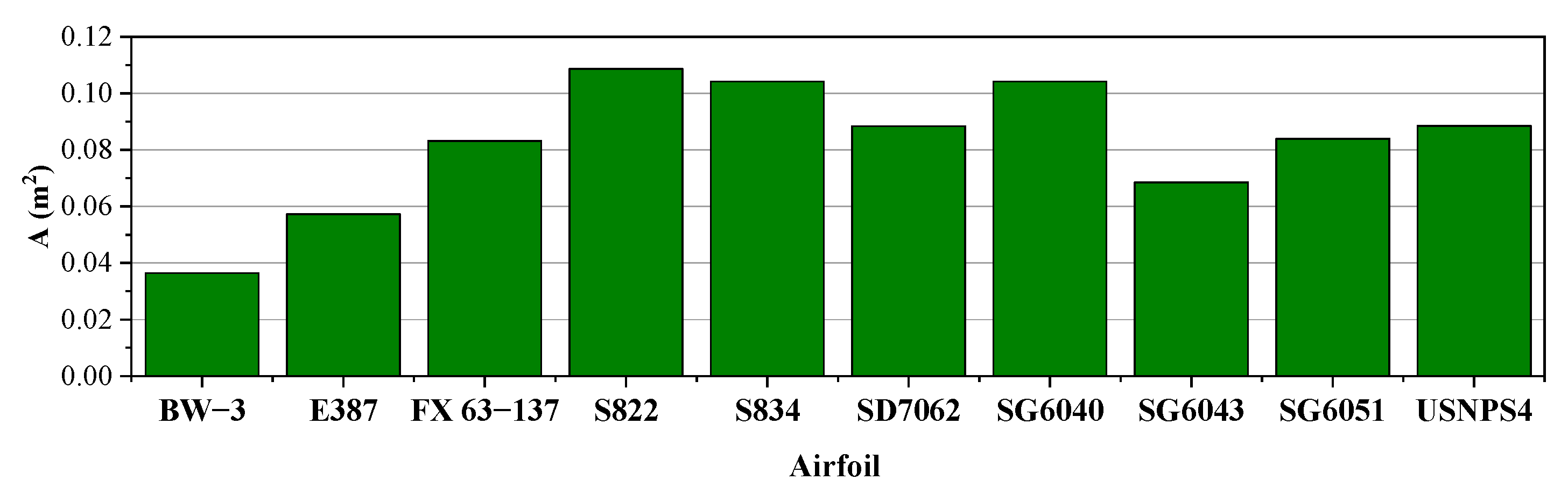
The S822, S834, and SG6040 airfoils have the highest
Ts and their application in areas with low wind speeds is not recommended at all. The common aspect of these three airfoils is their high surface area compared to the other selected airfoils, which is an effective factor in the blade moment of inertia, aside from the chord length (
Figure 14).
But it is also important to note that a thinner airfoil does not always present a better performance at low wind speeds. For example, the E387 airfoil is thinner than the SG6043 airfoil and has a smaller surface area (see
Figure 14), but it has a longer
Ts (
Table 4 for
n = 0.8). The reason is the higher moment of inertia and the lower startup torque (the startup torque is examined at the end of the current section) of the blades fitted with this airfoil compared to the blades fitted with the SG6043 airfoil.
Figure 15 shows the optimal distribution of twist and chord for the selected airfoils for
n = 0.8. By comparing this figure with
Figure 11, it can be observed that regardless of the airfoil type, raising the twist and chord values in the root part of the blade decreases the
Ts. It should be noted that during the startup process, the angles of attack along the blade are high, which decrease by raising the twist angle, and this increases the startup torque. However, since the blade root elements have a smaller share in power generation, the optimization algorithm applies these increments (twist and chord) only in this area so that the
Cp does not decline much.
Figure 16 shows the variations of startup torque during the startup time of the selected airfoils for
n = 0.8. Regardless of the airfoil type, as the blade begins to rotate, the startup torque initially decreases, and then it starts to increase. When the blade is stationary, the drag force is perpendicular to the direction of rotation and does not affect the startup torque. As the blade begins to rotate, the drag force reduces the startup torque, but then the startup torque starts to increase.
Figure 16 shows that the blade that uses the USNPS4 airfoil produces the highest startup torque, but having a high moment of inertia raises its
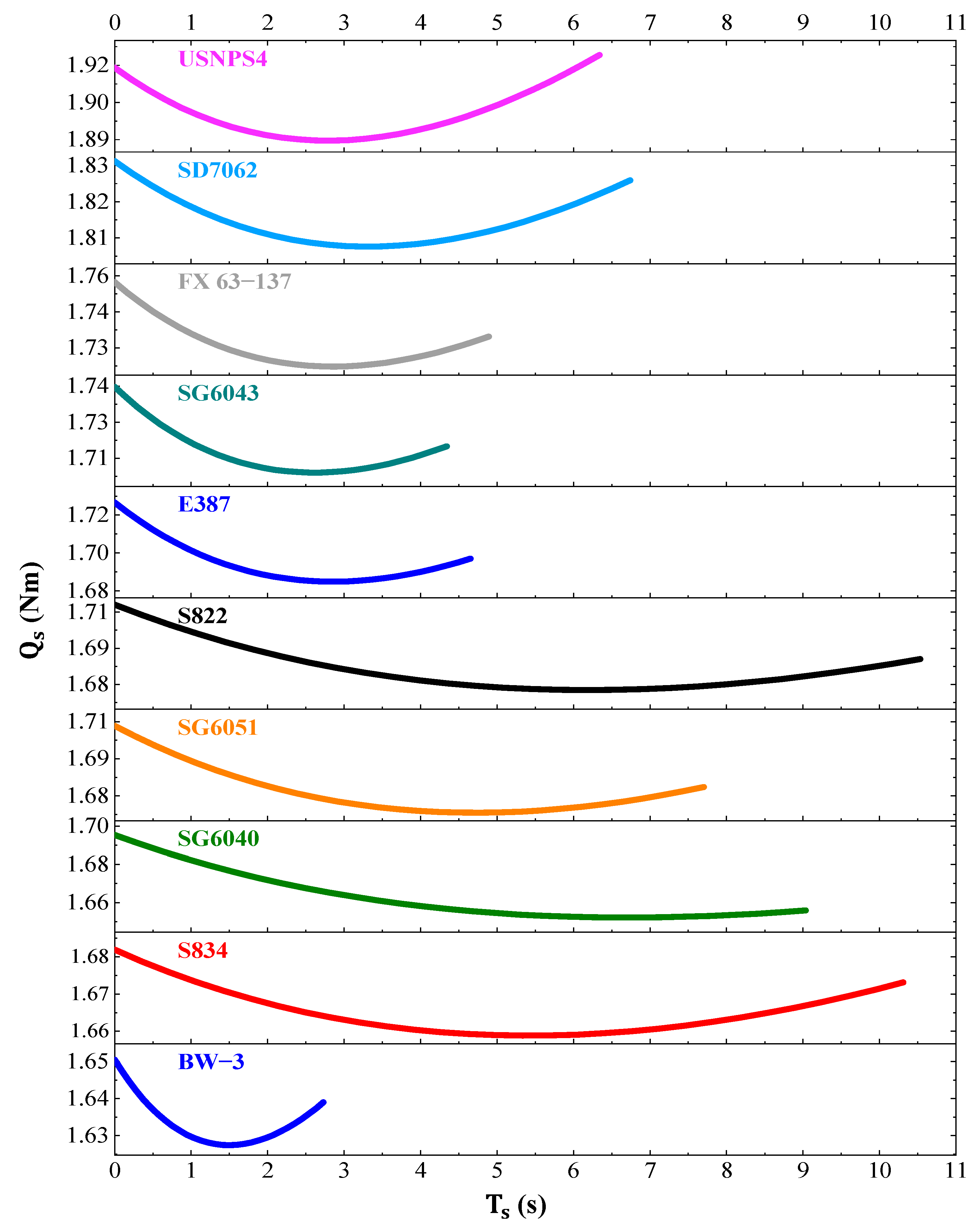
Ts. The lowest startup torque is produced in the blade with the BW-3 airfoil, but, as mentioned, its low moment of inertia is the advantageous aspect of this airfoil in areas with low wind speed. It is noteworthy that the startup torque is a function of two parameters, including the twist angle and the chord length (see Equation (10)). The difference observed in the values of startup torque for the selected airfoils is due to the different twist angle and chord length values that the optimization algorithm has considered for each airfoil. Finally,
Figure 17 summarizes the performance of the selected airfoils in terms of
Cp and
Ts. The arrangement of these airfoils is based on exhibiting the highest
Cp in windy areas and having the shortest
Ts in areas with low wind speeds.


 ,
, 


