1. Introduction
In recent years, many countries have been implementing an “energy transition,” i.e., the creation of a decentralized low-carbon energy infrastructure equipped with digital devices [
1,
2,
3]. The model of consumer behavior is also changing. Consumers become prosumers actively influencing the operating conditions of power distribution networks through effective management of their demand, distributed generation (DG) facilities [
4], and power storage systems [
5,
6].
Owners of DG facilities use available primary and secondary energy resources to generate the necessary types of energy (electrical, thermal, cooling) [
7]. They also factor in the legislative requirements for reducing greenhouse gas emissions, ensuring energy efficiency and energy saving [
8]. An important factor stimulating industrial entities to build DG facilities is the need to provide the reliability of power supply and the quality of electricity on the buses of essential power consumers participating in a continuous production process [
9,
10].
Secondary energy resources in the metallurgical industry are blast-furnace and converter gas, in the mining industry, coal mine methane, in the agricultural industry, timber processing and food production waste, in housing and communal services, biogas at sewage treatment plants and waste processing plants, and others [
11,
12]. Efficient recycling of secondary energy resources at DG facilities minimizes the negative environmental impact of an industrial entity, improves the environmental situation, and reduces the production cost of the necessary types of energy [
13]. Gas-reciprocating units (GRUs), which have a wide range of capacities and are supplied by various manufacturers, have been widely used at DG facilities [
14].
This is due to the fact that GRUs have some advantages over gas turbines (GTUs) and diesel generator sets (DGSs). Unlike gas turbines, current and major repairs of GRUs can be carried out at the place of their installation, without dismantling and sending to the manufacturer. Most of the GRU maintenance and repair can be made by repair personnel of industrial entity after training at the manufacturer’s site. GRUs, in comparison with GTUs, have a lower specific gas consumption at a high efficiency (40–44%) and can operate under the minimum power consumption, without reducing the resource. In contrast to DGS, GRU uses cheaper fuel. With a propane-butane gas mixture used as a reserve fuel, the cost of generating 1 kWh of electricity by GRU will be 1.2–1.4 times less than by DGS.
DG facilities with GRUs are connected to the internal power systems of industrial entities, normally, at a voltage of 10 kV. This enables optimization of power flows in these networks, enhancement of the power quality by improving the voltage regulation process on the buses of electric loads, and minimizes power losses [
15,
16].
The connection of DG facilities to the internal power systems of industrial entities makes the GRUs closer to the electric motors being part of the load. For this reason, electromechanical transients become common for them [
17]. In a case where the total power of electric motors within the load of an industrial entity is comparable to the total power of the GRU at the DG facility, the nature of the transient processes will be determined to a greater extent by characteristics of electric motors. Therefore, mathematical modeling of electric motors in the calculations of steady-state conditions and electromechanical transients in the internal power systems of industrial entities should be performed as correctly as possible, within the limits of permissible simplifications [
18].
In the case of accidents in the power distribution network, internal power systems with one/several DG facilities can be islanded to ensure reliable electricity supply to consumers in the amount of available power [
19,
20]. The islanded mode of operation is understood as the internal power system operation that meets the power consumption conditions, occurs when all power lines connecting the internal power systems to the power distribution network are disconnected (due to a short circuit; without a short circuit) and exists until the internal power system is synchronized with the power distribution network [
21].
The analysis of statistical data on GRU-based DG facilities shows that improper consideration of possible GRU operating conditions when designing the DG facility can cause damage of GRUs and their excessive shutdowns. This is accompanied by a complete or partial shutdown of continuous production processes at industrial entities and significant damage and losses due to undersupply of products [
22,
23].
Consequently, the known approaches adopted in the design of backbone networks, large conventional power plants and industrial power systems are unacceptable without regard for specific features of DG facilities.
The paper aims to identify the features of operating conditions of GRU-based DG facilities in the internal power systems of industrial entities and to justify changes in the approaches to their design. The paper presents technical solutions that make it possible to prevent GRU damage and excessive shutdowns, and to ensure reliable power supply to electric loads of industrial entities in the case of an islanded mode of operation.
2. Overview of the GRU Functioning Issues
An analysis of reliability indices of GRUs shows that they have only 2–5% lower availability factors compared to large gas turbine and steam turbine units of thermal power plants. However, they have lower mean time between forced outages, as their outages occur 5–8 times more often.
The mean time between forced shutdowns of GRUs is 1338 h, which is in the range of 785–3583 h (rising with an increase in GRU power from 100 kW to 3 MW). The reasons for the GRU outages caused by their internal damage or deviations of the operating parameters beyond the limits of permissible values account for 32.5% of the total number of outages, and those associated with external emergency disturbances (in adjacent distribution networks or internal power systems of industrial entities) make up 67.5% [
24].
In severe operating conditions, the reliability indices of the GRU deviate downward by more than 40% from those given above. Severe operating conditions imply load following operation; daily starts/stops, including cold ones; long-term islanded operation with large load surges/drops; non-compliance with the service interval; fuel quality that does not meet the requirements, and others. Most of the above conditions are due to the operating conditions of the internal power system and the power distribution network.
The islanded operation of the internal power system, when the GRU-based DG facility is the main source of electricity, significantly increases the requirements for the reliability of its operation. In addition, a GRU-based DG facility and a power distribution network can function in parallel through a “weak tie line” (long power transmission lines with low transfer capability, which are characterized by a large inductive resistance), which affects the GRU operation.
The informed technical decisions to be made when designing GRU-based DG facilities integrated into the internal power systems of industrial entities require an analysis of the issues encountered during GRU operation at real DG facilities [
25,
26].
The advantage of the paper is that all the above issues arose at real DG facilities during their operation, and all the consequences of accidents are examined based on the acts of investigation into the causes of their occurrence. Since additional capital investments were required to cope with the problems, the economic indicators of projects for construction of GRU-based DG facilities deteriorated sharply, and in some cases, they became economically unfeasible.
The paper presents the results of the calculations of electromechanical transients, which were performed with the MUSTANG-90 software (Russia). In doing so, in the network design diagrams, we:
presented the power grid by infinite buses, with all external sources of equivalent constant EMF behind the resistance corresponding to the short circuit power;
used verified mathematical models of GRUs and relay protection settings specified by GRU manufacturers;
assumed the power consumed by electrical loads in the internal power system of industrial entity (basic design scenario) as follows: synchronous motors—10%, induction motors (IMs)—62%, static load—28%;
applied reduction of 6 kV IM groups connected to one 6 kV busbar by the replacement with one IM with the total nominal active power and weighted average (with respect to Pnom.i) values of nominal, maximum and starting torques, starting current, tgφnom, and the resistant torques of driven mechanisms;
applied reduction of 0.4 kV induction motors connected to one 0.4 kV busbar by replacement with one IM connected to 6 kV busbar through the resistance of a 6/0.4 kV step-down transformer;
used settings of relay protection devices of power receivers, power transmission lines and power transformers in the internal power system of an industrial entity, and supplying of 110 kV power transmission lines according to the setpoint charts of relay protection devices.
The calculations of electromechanical transients involved modeling of the following types of emergency disturbances:
a short circuit on one of the 110 kV transmission lines (the second transmission line was put out for repair) supplying the internal power system of an industrial entity, near the 110 kV substation busbars;
successful non-synchronous automatic reclosing of a 110 kV power transmission line, restoring the connection of the internal power system of the industrial entity to the power grid, with self-starting of electric motors;
unsuccessful automatic reclosing of the 110 kV transmission line, which results in switching the internal power system of industrial entity to islanded operation;
direct start-ups of large IMs from GRUs during the islanded operation of the internal power system of an industrial entity.
The paper summarizes the causes of problems encountered by various GRU-based DG facilities over the past 10 years. The presented results of calculations of electromechanical transients allow a deeper understanding of the topology and operating conditions under which these problems with GRUs manifested themselves. The paper considers situations with GRUs of various manufacturers, which were put into operation at industrial entities in various industries.
In the past, the internal power systems of industrial entities were passive, i.e., they did not include generating plants [
27] and all electrical loads were powered by external distribution networks. The main objective to be accomplished in the design is to ensure sufficient transfer capability of power transmission lines and permissible voltage levels on the buses of power receivers in post-emergency conditions for all topology and operating conditions [
28]. This is essential to provide successful self-start of electric motors as part of the load and their further functioning. The principles of designing internal power systems of industrial entities were developed by power supply experts and tested on many real-world facilities, which are still in operation.
Historically, regulatory and technical documents, including methodological recommendations for the design of power distribution schemes (PDSs) of power plants, were developed on behalf of, and with the participation of, operators of backbone and distribution networks. The main objective of the PDS development is to factor in the topology and operating conditions, considering regulated disturbances in adjacent networks, in order to ensure the stable functioning of power systems [
29]. In most cases, power plants are connected to the power system at a voltage of 110 kV and above. If the generating equipment of the power plant causes stability loss in the power system, measures must be taken to turn it off. Priority is given to seamless operation of the power system, which ensures parallel operation of most power plants and reliable power supply to the main consumers. The PDS projects must consider the topology and operating conditions for the year of putting a power plant into operation, and for a period of up to five years.
The integration of GRU-based DG facilities into the internal power systems of industrial entities made their networks active [
30]. The GRU-based DG facilities are connected to the internal power systems of industrial entities at medium or low voltage and have a relatively small capacity, Therefore, the operators of backbone and distribution networks do not take into account their impact on the power systems. For this reason, it is not necessary to change the principles of PDS development in terms of the stable functioning of power systems [
31]. Since all industrial consumers have different owners, it is inefficient for any of them to finance the development of a new regulatory and technical document for one project of a DG facility. Given that internal power systems and load structures at industrial entities of various industries are different, it is difficult to develop universal methodological recommendations for designing them.
Therefore, design organizations tend to use separate regulatory and technical documents for the development of PDS of power plants and the design of internal power systems of industrial entities. These documents do not consider the specific features of power flows and electromechanical transient processes in the internal power systems of industrial entities with DG facilities. Therefore, there is a high probability of design errors, especially if the aim is to ensure a reliable power supply to electrical loads of industrial entities in islanded mode. All responsibility in this case lies with the specialists of the design organization and depends entirely on their qualifications.
If the main purpose of the DG facility construction is purely economic, which involves reducing the cost of purchasing electrical energy from the external network, then not too frequent shutdowns of GRUs, given their quick restart capability, will not lead to significant damage [
28]. However, if the aim is to ensure reliable power supply to power consumers from GRUs in islanded mode, their cessation under short-term frequency and voltage deviations causes a complete shutdown of technological processes.
Some points discussed in the paper are closely interrelated and require special attention from the experts involved in designing GRU-based DG facilities. Comprehensive consideration of their possible operating conditions allows the making of sound technical decisions to ensure both the reliable operation of the GRU and reliable power supply to electrical loads of an industrial entity.
The analysis of accidents at DG facilities, calculations of electromechanical transients and their generalization given in the paper are our contribution to the improvement in methodological foundations for designing DG facilities in the internal power systems of industrial entities.
2.1. Mechanical Damage of the GRU
There are known cases where the accidents that occurred at the GRU-based DG facilities were associated with damage to the GRU shaft line, cracks and destruction of the crankshaft, and damage to the connecting rod and piston group [
18].
An analysis of the causes of accidents showed that most modern GRUs, given their strength characteristics, are not designed for the use of unsynchronized reclosing in the power distribution network. Dangerous operating conditions can occur in the repair schemes of the supply distribution network, when one of the power lines is under repair and the industrial entity is powered from the DG facility, or from one power line on which the unsynchronized reclosing device is installed.
In the event of a short circuit on the power line and its disconnection by the relay protection, followed by the operation of the unsynchronized reclosing device, at the moment the connection with the power distribution network is restored (the unsynchronized reclosing is successful, the short circuit has self-cleared), the electromagnetic impact-torque acts on GRU. The value of this torque for synchronous generators without a damper winding can be 3.2 times greater than that in the case of a three-phase short circuit at terminals, and for synchronous generators with a damper winding of 1.7 times, which makes up 12–13 Mnom.GRU. It is worth noting that most low-power (several MW) synchronous generators used in GRUs do not have a damper winding.
Most GRUs produced by manufacturers are designed to withstand an electromagnetic impact torque equal to 8–9 Mnom.GRU, which occurs on the shaft of a synchronous generator in the case of a three-phase short circuit at terminals, but they are not designed for 12–13 Mnom.GRU at unsynchronized reclosing.
The relay protection devices of the GRU synchronous generators cannot prevent the electromagnetic impact torque [
32,
33]. This is because the electromagnetic impact torque reaches its maximum value after 5 ms from the time of unsynchronized reclosing operation. During this time interval it is impossible to recognize the dangerous condition and turn off the generator circuit breaker. The real shutdown time of the GRU, given the response time of the starting element and the opening time of the generator circuit breaker, will be at least 50–70 ms. Consequently, the GRU synchronous generator will be disconnected from the already damaged network.
Figure 1 shows a graph of the change in the electromagnetic impact torque at the GRU for a short circuit on power transmission line and for unsynchronized reclosing (the unsynchronized reclosing pause for the electric arc deionization on the 110 kV overhead power transmission line is equal to 2.2 s).
Following the characteristics given in the technical documentation for the GRUs, in order to exclude their damage during operation, it is necessary that their design be based on one of the following solutions:
exclude the use of unsynchronized reclosing in the power distribution network by replacing it with automatic reclosing (AR) with synchronism control (AR with synchronism expectation; AR with synchronism detection) [
34];
ensure that the circuit of the stator of the GRU synchronous generator includes a current-limiting device (CLD) with a resistance sufficient to reduce the magnitude of the electromagnetic impact torque to an acceptable value [
35];
connect the GRU to the internal power system of an industrial entity through a frequency converter (a non-standard solution difficult to implement);
agree with the manufacturer about replacement of conventional clutch between the drive gas-fired reciprocating engine and the synchronous generator with a limit torque clutch, which, when the maximum allowable torque is exceeded, disconnects the shafts, thereby reducing the impact on the line of shafting.
The first of the proposed technical solutions is more preferable and the least economically costly. However, it requires reconstruction at substations in the power distribution network owned by other owners.
The second technical solution is the use of CLD of various types. The devices that can be used as CLD are a current-limiting reactor (CLR) [
36], an isolation transformer (power transformer with increased short-circuit resistance and a transformation ratio of 1/1); high-speed CLDs based on different principles, including power electronics, high-temperature superconductivity, explosive type, and others [
37,
38].
In the case of using CLR, the relative resistance
x, necessary additionally to the values
x”d and
x”q of GRU synchronous generator, is calculated based on the resistance
XCLR (Ohm) by expression (1):
where ∑
Snom.GRU is the total nominal power of the synchronous generators of the DG facility connected through CLR to the power distribution network;
Unom.GRU is nominal voltage of synchronous generators of the DG facility.
The use of CLR is the cheapest solution. At the same time, the industry produces high-speed CLDs with the resistance XCLD = 0 in normal operating conditions, but it quickly increases (is introduced into the electrical circuit) during short circuit and unsynchronized reclosing. To prevent GRU damage during unsynchronized reclosing, CLD should limit the current in 2–3 ms after it starts rising. This circumstance significantly increases the requirements for CLD making them more difficult to fulfil.
The third technical solution is quite expensive, therefore, normally, it is not used in GRUs. However, solutions for gas turbine plants are widely known [
39]. Connection of GRU to the network through a frequency converter makes it possible to prevent its damage during short circuit and unsynchronized reclosing, since the automatic control system implements a current limiting algorithm that reduces the current to the value 1.1–1.4
Inom. In this case, the GRU does not disconnect from the network, but reduces the current to the maximum allowable value [
40].
However, if the GRU-based DG facility is in the islanded mode of operation, being the only source of power supply, then problems with ensuring the sensitivity of the relay protection devices arise. In this case, a mass reconstruction and replacement of relay protection devices in the internal power system of an industrial entity are necessary. Most typical relay protection devices respond to the current exceeding a given setting, but in this case, we need relay protection devices that can detect and localize the fault site at short-circuit currents close to the overload current [
41,
42].
The fourth technical solution is based on the use of a limit torque clutch. In one of the clutch design solutions, shafts of synchronous generator and gas reciprocating engine are connected through special lamellas with springs. An unacceptable increase in the synchronous generator speed, resulting from the electromagnetic impact torque, causes a slip in the clutch, which reduces the effect on the gas reciprocating engine to an acceptable value. This solution, however, is applied only to low-power GRUs.
GRUs of higher power employ shear pin couplings. Replacement of the pins in the coupling is much cheaper than the overhaul of a gas reciprocating engine. However, it should be borne in mind that it takes at least 6–8 h to replace the pins and balance the GRU in operation. During this time, it is necessary to ensure reliable power supply to the electrical loads of an industrial entity from other sources.
2.2. Disconnection of GRU during High Load Surges
In gas reciprocating engines of GRU, when the shaft speed drops below the minimum allowable value, the pressure necessary to ignite the working mixture in the compression phase in the cylinders is not provided. If the GRU lubrication system is driven by a camshaft, in the absence of a backup oil electric pump, then at a low GRU speed, the oil pressure may not be sufficient to continue normal operation. In this case, the GRU will be switched off by process protection.
The more power the GRU develops the more air supply it requires for its proper functioning. Air is supplied to the gas reciprocating engine through the compressor, which is rotated by the compressor turbine, and its working medium is the exhaust gases of the GRU. This provides turbocharging.
With an increase in the GRU load, with a decrease in the output shaft speed, the automatic control system increases the fuel supply, the GRU power goes up and the volume of exhaust gases rises. At the same time, the speed of the compressor turbine and of the compressor increase, which ensures the required air supply to the gas reciprocating engine.
The large moment of inertia of the compressor turbine-compressor system prevents rapid changes in the turbocharging value, which is why GRU starts to generate more power with a delay (about 1 s) in relation to the electric load surge. This delay is not dangerous during load shedding, whereas during surges it leads to overheating of the gas-reciprocating engine, and the greater the magnitude of the load surge the greater the overheating.
The known methods of improving the throttle response of gas reciprocating engines by accelerating the response of turbocharging to an increase in fuel supply are called “bi-turbo” and “twin-turbo”. Turbocharging devices are connected in series or in parallel, which reduces their inertia, thus allowing them to be controlled according to different algorithms, and increases their throttle response.
In the presence of turbocharging, the response of a gas reciprocating engine to load surges and shedding at GRU differs significantly.
Figure 2 shows graphs of electromechanical transients with GRU during the static load surge/shedding with the value equal to 15% of
Pnom, which does not depend on frequency and voltage of the synchronous generator.
Analysis of
Figure 2 shows that with the load surge on the GRU synchronous generator, within the available power limits, the delay in turbocharging can lead to the GRU tripping by process protection, which causes serious consequences for the DG facility in the islanded mode of operation, when it is the main source of electricity for the load.
Under these conditions, GRU manufacturers impose restrictions on the maximum allowable values of sudden load surges (from 5 to 30%), depending on the initial load (from
P0 to
P0 + Δ
P). They are often presented in the form of graphs (
Figure 3a) given by four different GRU manufacturers. In addition, manufacturers standardize the permissible interval between load surges, which should be at least 1–2 min.
Figure 3b shows the “classes” of GRUs of the same type, depending on which the magnitudes of load surges differ. Since the throttle response of the “class 1” GRU is higher, its cost is correspondingly higher as well [
18].
Analysis of
Figure 3 makes it possible to conclude that if the GRU operates at a technological minimum load of 40%, then the maximum allowable load surge can be no more than 5% for some GRUs, and no more than 23% for the most responsive ones. If an industrial entity has large direct-start electric motors or production lines that can cause large sudden load surges, this must be factored in when designing the DG facility. Otherwise, each start-up of such a load will end with shutdown of the GRU and the complete outage of all electrical loads in the internal power system.
To prevent shutdowns of the GRU operating in the islanded mode, designers should envisage the following technical solutions:
2.3. Excessive Disconnections of GRU by Relay Protection Devices
Some manufacturers of GRUs choose relay protection settings that can lead to their frequent excessive disconnections, especially in the islanded mode of operation. This interferes with the normal functioning of GRU and causes damage from shutdowns and losses from undersupply of products at industrial entities.
It can be difficult to coordinate the relay protection settings of GRU and components of the internal power system of an industrial entity (power transmission lines; power transformers; electric motors), and the power distribution network. While it is still possible to provide the selectivity of the operation of the main and local backup protections (they operate without a time delay), it is impossible to coordinate the settings of the remote backup protections (selectivity is ensured by time settings).
This significantly narrows the range of feasible operating conditions for the GRU and makes it impossible to provide reliable power supply to electrical loads of industrial consumers from DG facilities operating in islanded mode. Thus, industrial entities fail to achieve the main goal of building a DG facility.
It is important to note that the GRU relay protection settings cannot be changed without agreement with the manufacturers. In the event of an unauthorized change in the settings of the GRU relay protection devices by the buyer, the warranty obligations are canceled by the manufacturer unilaterally, according to the terms of the supply contract.
If the main purpose of the GRU-based DG facility is only to produce electrical and thermal energy through the efficient utilization of secondary energy resources, then excessive shutdowns of GRUs, given their quick restart, do not cause problems. The situation is similar if GRUs are used to reduce the cost of purchasing electrical and thermal energy from the external power grid. However, if the DG facility is used as the main source of power supply in the internal power system operating in the islanded mode in order to ensure reliable power supply to consumers, then the approach of GRU manufacturers to the choice of settings for the GRU relay protection is unacceptable.
Switching the internal power system to the islanded mode of operation, in particular by the islanding scheme, is accompanied by significant short-term voltage and frequency deviations [
47]. Therefore, operation of the GRU relay protection devices must be tuned with time settings (at least 2–4 s) in the case of frequency and voltage deviations.
It is worth noting that the choice of GRU relay protection voltage setting to reduce voltage without current control is not justified. The risk of thermal damage to the windings of a synchronous generator arises if the frequency and/or duration of emergency overcurrent of the stator or rotor exceed the permissible values [
48]. The values of current are set by the manufacturers, given the heat resistance class (temperature index) of the winding insulation and in relation to the temperatures of the cooling medium of the stator and rotor windings. If the values of magnitude and duration are exceeded for the stator current, the relay protection devices act to disconnect the GRU from the network, and if that occurs for the rotor current, the relay protection devices act to reduce the excitation current (excitation deforcing) to a value that excludes dangerous overheating of the rotor winding [
49].
Consider a simplified single-line diagram for connecting an industrial entity with a DG facility (4 GRUs of 2.4 MW each) to a 110 kV distribution network, presented in
Figure 4.
If a three-phase short circuit occurs in the power distribution network on a 110 kV transmission line (at some distance), then all 4 GRUs at the DG facility are disabled by the relay protection of GRUs (the voltage reduction setting is 0.9 Unom, the protection response time setting is 0.2 s).
Figure 5 shows an electromechanical transient during a three-phase short circuit on a 110 kV transmission line with a duration of 0.18 s.
Analysis of
Figure 5 shows that all 4 GRUs are disconnected after the short circuit clearance by correct action of relay protection devices on the 110 kV power line. After the short circuit is cleared, self-starts of electric motors begin in the internal power system of the industrial entity. This makes the voltage remain lower than the operation setting of GRU protection for 0.4 s from the moment the short circuit begins. If the operation time setting of the GRU protection were chosen to be 0.5 s, the GRU shutdowns could be avoided, given that these operating conditions are absolutely not dangerous for the GRU.
Experience in calculating electromechanical transients in internal power systems of industrial entities with GRU-based DG facilities shows that the duration of self-starts of electric motors at industrial load nodes after the clearance of a three-phase short circuit is approximately equal to the short circuit duration if it is eliminated in 0.2–1 s. With a longer duration of short circuit, self-starts of electric motors become either protracted or impossible as a result of stalling.
Analysis of statistical data on the number of short circuits in the internal power systems of an industrial entity and the power distribution network suggests that the number of short circuits in a 10 kV network in an annual context is approximately 10 times higher than the number of short circuits in a 110 kV network. Given that 10 kV transmission lines, are normally equipped with time selectivity overcurrent protections, the short-circuit clearance time there is 0.5–1.5 s. Therefore, if the time setting of the relay protection device of GRU is not increased to 2–4 s, then with each short circuit in the 10 kV network, there will be an excessive (non-selective) shutdown of all GRUs at the DG facility, which is unacceptable.
In the event that it is impossible to agree upon changes in settings of the GRU relay protection devices with the manufacturer, it is necessary to envisage the complete replacement of relay protection devices in the internal power system of an industrial entity, and their partial replacement in the distribution network [
50,
51].
It is worth noting that part of the GRU manufacturers either set the parameters of relay protection devices that do not lead to excessive shutdowns of GRUs, or agree to change the settings, which allows them to be harmonized with the settings of the relay protection devices in the adjacent network. Sometimes, the results of calculations of electromechanical transients with a map of settings for relay protection devices in the adjacent network are required for the manufacturer to approve changes in settings.
2.4. Contribution to the Voltage Avalanche Development
Voltage avalanche in the internal power system of an industrial entity with a GRU-based DG facility can take place due to active power shortage, which is close to a critical value (Dcr). This condition can occur when the internal power system with the DG facilities is switched to an islanded mode of operation with most of the load covered not by the DG facility (some GRUs are under current or major repairs) but by the power distribution network.
The value
Dcr depends mainly on the number and load of operating GRUs, as well as on the total power of the switched-on electric motors (EM). The more power is consumed by the electric motors as part of the load, the easier it is for the voltage avalanche to occur and the lower the value
Dcr will be. Experience in calculating the electromechanical transients shows that the value
Dcr ≈ 70–75%. Dependence of
Dcr on the proportion of electric motors in the load in the islanded mode is shown in
Figure 6a. The minimum amount of load shedding required to prevent a voltage avalanche, with a share of electric motors of 80%, is shown for different values of
Dcr in
Figure 6b.
Analysis of
Figure 6a indicates that if the proportion of electric motors in the load approaches zero, then there are no conditions for a voltage avalanche to occur, and the value
Dcr tends to 100%.
If the active power shortage results from a short circuit, then its value should be determined not at the moment of islanding (the beginning of the accident), but immediately after the short circuit clearance. By this moment, the electric motors have had time to slow down to a greater or lesser extent, which leads to an additional decrease in voltage and the value of Dcr will increase.
In the event of a shortage of active power in the islanded mode, a load surge occurs at GRUs remaining in operation.
Section 2.2 of the paper indicates that all GRUs have maximum permissible values for sudden load surges, the magnitude of which depends on the initial load.
One of the ways used by manufacturers to mitigate the impact of sudden load surges on the GRU is to implement the impact on the excitation controller of the GRU synchronous generator according to a given algorithm. The device that implements it (reduction in the voltage setting with a decrease in the shaft speed) is called the “Load Agreement Module” (LAM).
The calculation results for electromechanical transients confirm the possibility of obtaining a significant positive effect from the use of LAM, if the load in the internal power system of an industrial entity has a significant voltage-regulating effect of the load active power. The regulating effect for the selected normal operating conditions is determined by the expression (2):
where
Unorm is voltage under normal operating conditions of the network;
Pnorm is the value of active power consumed under normal operating conditions of the network.
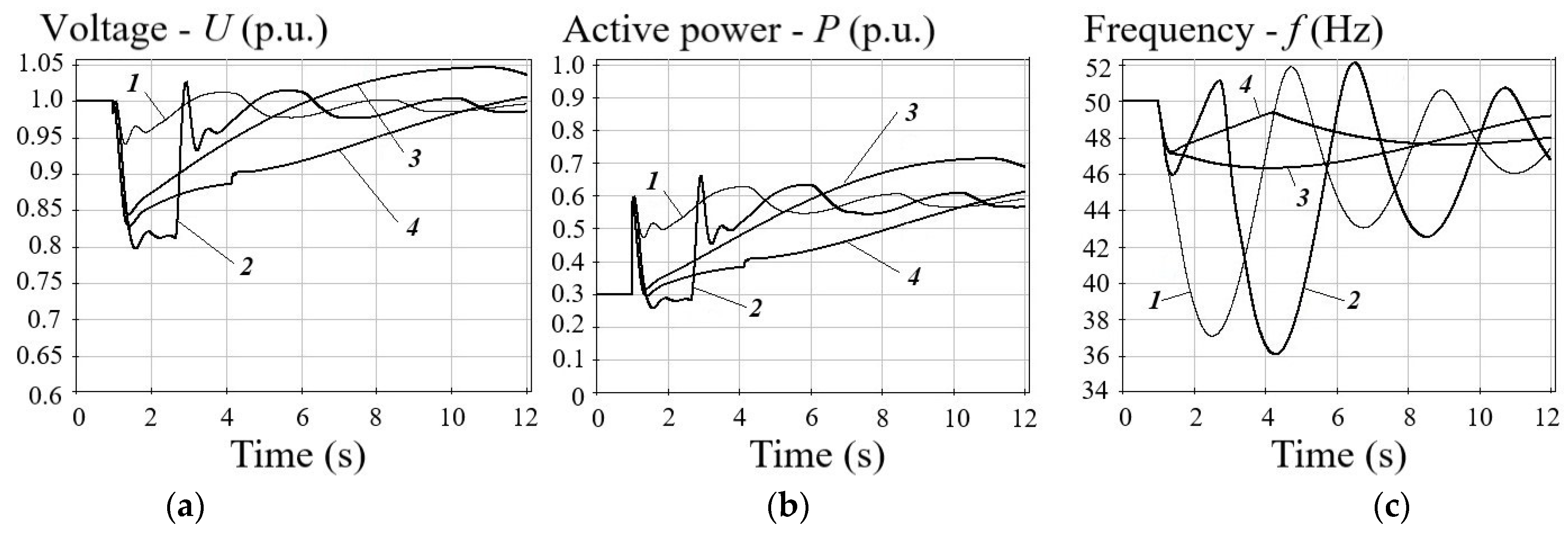
In the electromechanical transient process (
Figure 7), the voltage-regulating effect of load active power
KPU ≈ 1.9 p.u., the proportion of electric motors in load is 5%, the remaining load is static electrical loads, the initial load of GRU
P0 = 0.3
Pnom, load surge Δ
P = 0.3
Pnom. In
Figure 7, curve
1 corresponds to a typical excitation controller of a GRU synchronous generator; curve
2 is the first LAM algorithm; curve
3 is the second LAM algorithm; curve
4 is the resulting action of LAM.
Analysis of
Figure 7 shows that with a typical excitation controller at the GRU synchronous generator, the frequency decreases by 13 Hz (curve
1), and when LAM is used (curve
4), it declines by 3 Hz. A quick voltage return to
Unom (curve
2) leads to a sharp increase in the amplitude of the second and subsequent frequency oscillations up to 14 and 7.5 Hz, respectively.
Since the positive effect of the LAM action (reduction in the voltage setting) is based on a significant dependence of power consumption on the voltage value, with an increase in the share of electric motors in the load structure, the KPU will decrease, and so will the effect of LAM. In the internal power systems of industrial entities, electric motors predominate in the load, consuming 80–90% of the total load power.
Automatic transfer switch (ATS) is widely used in internal power systems to quickly restore load power in the event of a power failure at the working input. It is important to note that the transfer of power supply to electrical loads from one source to another by the action of ATS occurs with a dead time.
If the load surge on the GRU is preceded by a dead time of the ATS, the electromechanical transient differs from that shown in
Figure 7 by an additional voltage drop, due to the electric motor self-start currents. The use of LAM on the GRU in this case can provoke a voltage avalanche in the internal power system of an industrial entity, which is unacceptable.
An example of an electromechanical transient process during the load transfer by the action of ATS (dead time is 0.18 s) in the internal power system of an industrial entity is shown in
Figure 8.
Analysis of
Figure 8 (curve
4) indicates that during and after the dead time, the motors are braked, the voltage continues to decrease, and, as a result of the LAM action, the voltage in the network reaches the value of 0.4
Unom. Consequently, LAM provokes a voltage avalanche in the internal power system of an industrial entity, which upsets the operation of the entire load. Since the majority of electrical loads spontaneously cease to operate at the same time, the frequency in the network can be restored to the nominal value and even higher.
If the LAM action were blocked (curve 1), then the voltage at the outputs of the GRU synchronous generators would quickly recover. However, a decrease in frequency would trigger the operation of automatic frequency load shedding that would disconnect only a part of nonessential load in the internal power system. The power supply to an essential load would be maintained.
Thus, voltage decrease by the action of LAM is an effective measure to reduce the depth of frequency decline during load surges on GRU synchronous generators operating in islanded mode. This statement, however, is true under the condition that the value of the active load largely depends on the voltage KPU ≈ 1.9 p.u.
The action of LAM is unacceptable if it causes a voltage avalanche in the internal power system of an industrial entity, leading to complete power blackout. In this case, the LAM action in the excitation controller of the GRU synchronous generators should be blocked.
Whether it is admissible to use LAM in the excitation systems of GRU synchronous generators in specific internal power systems of industrial entities should be decided based on the calculations of electromechanical transients.
2.5. Selection of Control Algorithm in the GRU Excitation Controller
GRU synchronous generators are normally equipped with excitation controllers, in which one of four control algorithms can be selected:
providing automatic voltage regulation (AVR);
maintaining the set value of power factor, cosφ (PF);
maintaining the set value of generated reactive power (VAR).
maintaining the set value of the field current (FCR) [
52].
The AVR algorithm is rarely chosen for GRU synchronous generators, although it is the main one for high power synchronous generators used at large conventional power plants.
The GRU-based DG facilities often operate in load following conditions, both in islanded mode and in parallel with the distribution network, but supplying no power to it.
With the AVR algorithm, under changing load of the GRU while following the daily load curve of the internal power system of an industrial entity, it is possible to create conditions for the transition of synchronous generators to the under-excitation mode. This can happen because the AVR algorithm lowers the voltage setting on the synchronous generator when the bus voltage rises (night minimum load of an industrial plant) to prevent elevated voltage levels and increase in electricity losses in the network.
The need to compensate for excessive reactive power in the network affects the reliability of the GRU synchronous generators since the under-excitation mode is dangerous for them because they run close to the static stability limit. When reactive power is consumed in the end zones of synchronous generators, there can be local overheating, which leads to accelerated aging of windings. In addition, the dynamic stability of synchronous generators in the under-excitation mode is reduced and, in case of an emergency disturbance in the adjacent network, it can transform into out-of-step mode and be disconnected by the relay protection device.
Therefore, GRU manufacturers often choose the PF (less often VAR) algorithm when setting the excitation controller to optimize thermal conditions of the synchronous generator, which allows voltage coordination in the adjacent network by controlling various types of reactive power compensators. The FCR algorithm is rarely used.
The control algorithm in the excitation controller of the GRU synchronous generator operating in the internal power system of an industrial entity should be chosen based on the calculations of transient processes in order to ensure reliable power supply to power consumers under various topologies and operating conditions.
Let us consider an example with a load surge on the GRUs in operation after the elimination of a three-phase short circuit (one of the two power lines that supply the internal power system is tripped) as a result of the ATS operation. After the short circuit is cleared, when the voltage starts to recover, self-starts of electric motors begin, which leads to a decrease in voltage due to a rise in reactive currents. To increase the voltage recovery rate to the boundaries of the feasibility region and prevent shutdowns of the GRUs and electric motors, it is required to boost the output of reactive power by the GRU synchronous generators. If the PF algorithm is selected in the excitation controller, then it is impossible to implement boosting, since the excitation controller will continue to maintain the specified cosφ value.
If, however, the excitation controller of GRU selects the AVR algorithm, then, under similar conditions, in the event of a voltage dip during a short circuit, the excitation boost system will operate and the necessary voltage recovery rate will be provided on the power consumer buses after the short circuit is eliminated. A short-term increase in voltage to 1.12–1.15 Unom at the first moment of time after the short circuit clearance is not dangerous for the GRU, but it will significantly accelerate the self-start of electric motors.
It is worth noting that most electric loads at industrial plants, including variable-frequency drive (VFD) motors, are sensitive to voltage dips, as shown in
Table 1.
With lower values of residual voltage or exceeded specified duration time, there is a high probability that the loads will be disconnected with shutdown of a continuous production process at industrial entity.
When choosing a control algorithm for the GRU excitation controller it is necessary to pay special attention to its speed, since this is fundamental in the event of emergency disturbances. There are no speed requirements for PF/VAR algorithms, since they are designed to operate in steady-state conditions. Therefore, they are not able to provide a high rate of rise of the excitation current at the moment of short circuit and after its clearance.
We will consider the operating conditions of the internal power system of an industrial entity, which should be analyzed when choosing a control algorithm in the excitation controller of GRU synchronous generators:
direct starts of large electric motors or group starts of electric motors of technological lines in the islanded mode of operation of the internal power system (unsuccessful starts are unacceptable);
elimination of all types of short circuits by relay protection devices in the internal power system, including those in islanded mode, and in the distribution network (excessive shutdowns of GRU and the main electrical loads of the production process are unacceptable);
maintenance of voltage levels close to Unom (±5%) on the busbars of power consumers throughout the day, given the load curve (avoiding increased power consumption and power losses);
coordinated voltage control (primary/secondary regulation) in the internal power system of an industrial entity (avoiding conflict between GRU excitation controller and local automatic voltage control systems).
The technical decisions made on the basis of the calculation results should ensure optimization of reactive power balances in the internal power system in all its main operating conditions, which is the correct response to emergency disturbances, and reliable operation of power loads (electric motors) in post-emergency conditions.
In addition to checking the voltage conditions, it is necessary to determine the maximum allowable duration time for localization of close three-phase short circuits. This duration time decreases when the excitation controller switches from the AVR algorithm to PF algorithm and has a further reduction in dynamics when the excitation controller operating point is shifted from the nominal value of over-excitation (cosφ = 0.8) to the under-excitation range. Part of the GRU synchronous generators cannot work for a long time with cosφ = 1 or a value close to it.
2.6. Selection of Voltage Setting in the GRU Excitation Controller
Since the DG facilities are connected to the internal power systems of an industrial entity, apart from a control algorithm to be chosen in the excitation controllers of GRU synchronous generators, it is also necessary to choose the voltage setting, relative to which the regulation is carried out.
If the voltage setting in the excitation controller is chosen to be relatively low, then in the pre-emergency conditions, the reactive power of the load (Qload) will be covered mainly due to the power flow from the distribution network. Switching the internal power system to the islanded mode of operation will lead to a deep decrease in voltage, since the balance of reactive power will be disturbed and its shortage will occur.
The lower the voltage on the GRU-based DG facility buses the greater the depth of the voltage dip. With a voltage on the GRU buses equal to 0.95
Unom, the slip of the electric motor increases, the voltage goes down, and there is a high probability of a voltage avalanche, as shown in
Figure 9a. In this case, the load will be shed: initially due to a decrease in voltage, then due to a voltage avalanche that occurs after 0.1 s. As a result, power supply to essential power consumers in the internal power system of an industrial entity will be disrupted. In this case, the frequency will briefly go up to 54 Hz, and its steady value will be 51.5 Hz, if the GRU is not disabled by the relay protection devices, the probability of which is high.
If, in the operating conditions before islanding, the reactive power of the load (
Qload) is covered by the reactive power generated by GRU (the voltage on GRU buses is 1.05
Unom), then, in the case of islanding, the voltage drop in the internal power system of the industrial entity will be minimal. The voltage stability of electric motors being part of the load will be ensured, and the resulting shortage of active power will lead to a frequency decline (
Figure 9b). At the same time, automatic frequency load shedding devices will disconnect part of the non-essential load, while power supply to essential consumers will be preserved [
53,
54].
If islanding occurs, due to a three-phase short circuit near the busbars of a 110/10 kV substation, the stability of the electric motors will be quickly lost, which will lead to a deep decrease in voltage and load shedding (the frequency in the network will rise).
Figure 10a shows two electromechanical transients for comparison.
Given that this scenario is typical of the internal power systems of industrial entities and leads to a disruption in the production process, it is required that high-speed load shedding be performed at the time of their islanding.
Figure 10b shows the successful self-start of all electric motors in the internal power system during the high-speed load shedding after islanding. The calculation factors in the high-speed load shedding, performed 0.3 s after the start of the short circuit (0.1 s after its elimination), amounts to the initial active power shortage.
Therefore, to prevent possible disruptions in power supply to essential consumers during emergency disturbances in the distribution network, the voltage setting in the GRU excitation controller should be maintained at a level not lower than 1.01–1.05 Unom, and, in the case of islanding, the magnitude of high-speed load shedding should be equal to the initial active power shortage.
3. General Issues of Designing the Connection of DG Facilities
As shown by operating experience and analysis of findings of the investigation into the causes of accidents, the design of the DG connection to the internal power system of industrial entities should involve, in contrast to the recommendations of regulatory documents, a much larger number of power flow calculations [
55]. In doing so, it is necessary to factor in the many possible operating conditions of GRU and internal power system, as well as the analyzed groups of emergency disturbances with an assessment of the performance of various organizational and technical solutions.
All power flow calculations should be carried out for the parallel operation of the internal power system and power distribution network, islanded mode of operation, and the moment of islanding for various reasons (without a short circuit; as a result of a short circuit) [
56].
Here is a list of additional factors to be taken into account in power flow calculations:
possible algorithms for automatic speed controllers of the GRU (identification of operating conditions, parallel or islanded; transition from one control algorithm to another and vice versa);
control algorithms in excitation controllers of GRU synchronous generators (type of excitation system; presence of LAM);
calculation of a magnitude of impact electromagnetic impact torque at a close three-phase short circuit and unsynchronized reclosing to check the mechanical strength of the GRU (checking the performance of technical solutions to reduce it);
agreement between the settings of the GRU relay protection devices and the settings of the relay protection devices in the external power system (including that in the islanded mode; maximum and minimum load conditions) and power distribution network, with the development and verification of technical measures to expand the range of feasible conditions of GRU;
dynamic stability of the GRU and assessment of the consequences of the stability loss for the GRU and the load, with an analysis of the possibility and admissibility of spontaneous GRU resynchronization (assessment of the performance of measures to prevent the transition of the GRU to the out-of-step conditions);
success of direct starts of large electric motors or group starts of electric motors of process lines in the islanded mode of operation of the internal power system with various compositions of operating GRUs.
The issue of choosing the analyzed groups of emergency disturbances is extremely important, since the possibility of providing reliable power supply to consumers under various topologies and operating conditions depends on this.
Groups of emergency disturbances, both short-term (SC, AR, ATS, etc.) and long-term (emergency or scheduled repairs of equipment), should be formed taking into account the probability of their occurrence, as well as the amount of total annual damage.
The number of short-term emergency disturbances per year is much greater than long-term ones, although the latter lead to greater damage. Therefore, the largest total disturbances for the year can be both short-term, eliminated by relay protection devices, and long-term ones.
The list of analyzed emergency disturbances for each DG facility would be different. It depends on the GRU features, operating conditions of the DG facility, the structure of the distribution network and the internal power system, as well as the specific features of the production process at an industrial entity and on the load characteristics.
The issue of GRU stability is, as a rule, reduced to the requirement to maintain stability in the case of typical emergency disturbances set forth in the grid code. Typical disturbances include the ones in which power system stability must not be lost. More severe disturbances can cause a loss of stability.
To ensure reliable power supply to essential power consumers from the DG facility, it is not enough to carry out calculations only for the list of typical emergency disturbances. Therefore, design decisions on emergency response measures should be made on the basis of calculations for a list of non-typical emergency disturbances to reduce the negative consequences of accidents for an industrial consumer. It is unacceptable to ignore non-typical emergency disturbances, considering them to be too rare, since they can cause significant damage.
It is important to note that it is virtually impossible to develop standard design for connecting DG facilities to the internal power systems of industrial entities. One can create a set of standard technical solutions to be implemented at DG facilities and in the adjacent network, but, for a particular facility, the total number, and a set of such solutions, would be completely individual.
Let us analyze technical solutions, which, based on the power flow calculations, may need to be implemented at DG facilities and in the adjacent network according to the following criteria:
Low capital costs.
Low maintenance cost.
High efficiency of technical solution.
Experience in operating the equipment (devices).
Ease of choice and application, without additional feasibility studies, power flow calculations, and others.
The results of the analysis are summarized in
Table 2, where green, yellow and red colors show favorable, satisfactory and unsatisfactory compliance of the technical solution with the above criteria.
The design of DG facilities often tends to find a balance between conflicting restrictions, evaluates them from different perspectives, and, thereby, creates unique technical solutions and adaptive automation systems that implement completely different algorithms for introducing emergency measures for various operating conditions.
4. Conclusions
Gas reciprocating units have high availability factors. However, their shutdowns occur 5–8 times more often than those of large gas turbine and steam turbine units of thermal power plants. About 67.5% of the reasons for their shutdowns are related to the operation of internal power systems and power distribution networks, and 32.5% are related to internal causes, due to the specific features of the GRU.
To prevent damage to the GRU during unsynchronized reclosing, the unsynchronized reclosing devices should be removed from operation on power lines supplying industrial entities in the repair schemes of the distribution network, or automatic reclosing devices with synchronism control should be installed.
GRUs have a large moment of inertia of the compressor turbine-compressor system, which prevents rapid changes in the turbocharging value. For this reason, they gain power with a delay (about 1 s) in relation to the electric load surge. In order to prevent excessive shutdowns of GRU and disruptions in power supply of essential consumers with subsequent significant damage and losses from undersupply of products, it is necessary for the design to include a set of organizational and technical measures.
The connection of the DG facility to the internal power system of an industrial entity makes GRUs electrically closer to the electric motors being part of the load, and, thus, it is they, given comparable powers, which determine the nature and parameters of electromechanical transients during emergency disturbances in the adjacent network. It is important to take this into account when choosing the settings for relay protection of GRU.
When the internal power system with a GRU-based DG facility is switched to an islanded mode, active power shortage can be accompanied by deep voltage drops. The action of LAM in the excitation control system of the GRU synchronous generators must be blocked if its action provokes a voltage avalanche with a complete trip of the entire load.
GRU manufacturers, when setting up the excitation control, often choose the PF control algorithm to optimize thermal conditions of the synchronous generator and to coordinate voltage in the adjacent network by controlling the reactive power compensators. However, for the DG facilities in internal power systems of industrial entities, the AVR algorithm should be selected, factoring in the parameters of power consumers to ensure the required speed of excitation controller at the time of an emergency and in the post-emergency conditions.
It is unacceptable to choose a low voltage setting (0.95 Unom) in the excitation controller of a GRU, since islanding causes a deep decrease in the voltage on the buses of electric motors, which are then stalled and a voltage avalanche develops. In the event that islanding is accompanied by a short circuit, it is effective to use high-speed load shedding in the amount of the initial active power shortage.
Incorrect consideration of GRU features and possible operating conditions in the design leads to additional capital investments in organizational and technical measures in the course of operation. In this case, the economic indicators of projects for the construction of DG facilities grow worse sharply, and in some cases their implementation becomes economically unfeasible.
Design of DG facilities requires much more power flow calculations, including those for non-typical emergency disturbances. Direct application of the design principles used for backbone networks, large conventional power plants, and industrial power systems to GRU-based DG facilities in internal power systems is unacceptable.


 ,
, 


