Article

Lateral Stability Control of a Tractor-Semitrailer at High Speed

College of Automobile and Traffic Engineering, Nanjing Forestry University, Nanjing 210037, China
*
Author to whom correspondence should be addressed.
Machines 2022, 10(8), 716; https://doi.org/10.3390/machines10080716
Submission received: 21 July 2022 / Revised: 11 August 2022 / Accepted: 18 August 2022 / Published: 20 August 2022
(This article belongs to the Section Vehicle Engineering)

Abstract

:
To improve the high-speed lateral stability of the tractor-semitrailer, a lateral stability control strategy based on the additional yaw moment caused by differential braking is proposed and investigated based on the co-simulation environment. First of all, a five-degree-of-freedom (5-DOF) yaw-roll dynamic model of the tractor-semitrailer is established, and the model accuracy is verified. Secondly, the lateral stability control strategy of the tractor-semitrailer is proposed, two yaw moment controllers and the braking torque distributor are designed. Then, the effectiveness of the proposed control strategy and the influence of the yaw moment controller on the lateral stability of the tractor-semitrailer are investigated under the high-speed lane-change maneuvers. Finally, the controller robustness is discussed. Research results show that the proposed high-speed lateral stability control strategy can ensure the tractor-semitrailer to perform safely the single lane-change (SLC) maneuver at 110 km/h and the double lane-change (DLC) maneuver at 88 km/h; the yaw moment controller has significant influence on the lateral dynamic performance of the tractor-semitrailer; compared with the proportional-derivative (PD) control, the model predictive control (MPC) can make the tractor-semitrailer obtain better lateral stability under high-speed lane-change maneuvers; MPC and PD controllers exhibit good robustness to the considered vehicle parameter uncertainties.

1. Introduction

In recent years, tractor-semitrailers have become one of the most important means in the field of transportation because of its low transportation cost and high transportation efficiency. However, compared with single vehicles the maneuverability and stability of tractor-semitrailers are usually more difficult and worse due to their heavy weight, high position of the center of gravity (CG), and the coupling effect between the tractor and the trailer. For the common high-speed lane-change maneuvers on the highway, it requires the tractor-semitrailer can change to the adjacent lane at a speed of not less than 80 km/h, and sometimes even requires the tractor-semitrailer to realize continuous lane-change maneuvers at high speed. This process involves the instantaneous turning of the vehicle, and the probability of the tractor-semitrailer instability will greatly increase, often causing serious traffic accidents [1,2,3,4]. Therefore, the high-speed driving stability of tractor-semitrailers has always been a hot topic for scholars at home and abroad [5,6,7].
At present, typical control strategies applied to the stability control of tractor-semitrailers include the active steering of the trailer wheels [8,9,10], and providing the additional yaw moment by differential braking [11,12,13]. Compared with the active steering of the trailer wheels, the additional yaw moment provided by differential braking can improve the lateral stability of the vehicle more quickly, directly, and effectively. Furthermore, the additional yaw moment provided by differential braking does not need to make structural changes to the vehicle. Therefore, the yaw moment control through differential braking has received more attention in recent years. Li et al. investigated a vehicle stability control scheme integrating both the direct yaw moment control and active rear steering, the results showed that for different maneuvers the proposed control scheme can help to achieve substantial enhancements in the handling performance and the stability performance of the vehicle [14]. Elhemly et al. presented a semitrailer differential braking technique to improve the stability of a two-axle tractor combined with a three-axle semitrailer during evasive maneuvers at high speed. The proposed control strategy was based on monitoring of the yaw rate difference between the tractor and semitrailer, and applying differential braking on the semitrailer at a certain articulation rate threshold [15]. Lee studied an active trailer differential braking system and designed a linear quadratic regulator controller and a robust controller to enhance the stability of the car-trailer combination [16]. Cui et al. proposed a safety system which consisted of the autonomous steering subsystem and differential braking subsystem to mediate the conflict objectives of vehicle stability and rear-end collision avoidance in highway driving, and the simulation results demonstrated that the proposed safety system can effectively achieve better balance between an emergency collision avoidance maneuver and vehicle stability at high speed in different conditions [17]. Li et al. developed an integrated control system based on fuzzy differential braking for off-road vehicles, and the designed yaw and rollover control system was a two-level structure with the upper additional moment controller. The fuzzy proportional-integral-derivative (PID) was adopted to coordinate the yaw and rollover control simultaneously in the design of the upper integrated control algorithm. The implemented simulation results showed that the proposed control system could improve the vehicle yaw and roll stability, and prevent rollover happening [18]. Zhang et al. proposed an integrated control system that can simultaneously invoke differential braking and active steering of multi-axle vehicles, and the research results showed that the proposed system had better control performance than individual differential braking and individual active steering [19].
For the differential braking control, accurate additional yaw moment is very important. However, due to the influence of environmental factors and vehicle state parameters, a large deviation between the theoretical reference model established after simplification hypothesis and the actual vehicle model often exists, which leads to the inaccuracy of the additional yaw moment. Bai et al. adopted fuzzy PID control to obtain active yaw torque values of the tractor and semi-trailer [20]. Due to model predictive control (MPC) can mitigate the adverse effect of the time delay between the driver’s inputs and the responses of the vehicle dynamic states on vehicle stability control, more scholars prefer to obtain the additional yaw moment by the MPC. Li et al. designed a three-dimensional dynamic stability controller for the stability control, and the MPC was used to calculate the desired tire forces of four wheels [21]. Ataei et al. developed an integrated multi-objective controller for electric vehicles and provided a centralized structure to improve the overall stability of the vehicle. The unified integrated controller was developed using the MPC approach and the simulation results showed the effectiveness of the controller in improving the stability and safety of the vehicles in different situations [22]. Choi et al. presented a control scheme utilizing active front steering and differential braking for vehicle lateral stability, and captured the lagged characteristics of tire force based on the MPC using the extended bicycle model [23]. Jalali et al. studied the MPC of lateral stability of vehicles using coordinated active front steering and differential brakes [24]. Abroshan et al. developed a MPC to prevent the instability modes in a car-trailer vehicle equipped with differential braking [25].
The motivations and contributions in this study focus on two aspects. The first purpose is to design a lateral stability control system aiming at improving the lateral stability of the tractor-semitrailer under the SLC and DLC maneuvers at high speed. The second purpose is to reveal the influence of the yaw moment controller on the lateral stability of the tractor-semitrailer under the SLC and DLC maneuvers at high speed.
The remainder of this article is organized as follows. The dynamic model of the tractor-semitrailer is established in the following section. In Section 3, the stability control system for the tractor-semitrailer is proposed and designed. In Section 4, the numerical experiments and the results are discussed. Finally, in the last section, concluding remarks are provided.

2. Dynamic Modelling

In this section, a five-degree-of-freedom (5-DOF) yaw-roll vehicle model is established to represent the tractor-semitrailer and shown in Figure 1.
In Figure 1, each axle is represented by a single wheel. The pitch and bounce motions of the tractor-semitrailer and their aerodynamic force are ignored. The tire model used in this study is linear. The articulation angle between the tractor and the trailer is assumed to be small. The roll stiffness and the damping coefficient of the suspension system are constant in the range of the roll motions involved. The forward velocity of the tractor-semitrailer and the steering angle of the tractor’s front-axle wheel are given.
The dynamic model of the tractor-semitrailer comprises the motions of lateral, yaw and the sprung mass roll for both the tractor and trailer and the coupling constraints between them. As detailed in [1], the dynamic equations for the tractor and semitrailer can be developed using body-fixed coordinate systems x1y1z1 and x2y2z2, respectively. Applying Newton’s second law to the tractor and semitrailer, we can obtain Equations (1)–(6), wherein Equations (1)–(3) are used to describe the motion of the tractor (lateral force equation, yaw moment equation, and the sprung mass roll moment equation), and Equations (4)–(6) are used to describe the motion of the semitrailer (lateral force equation, yaw moment equation, and the sprung mass roll moment equation). In the following equations, subscript 1 denotes the tractor, subscript 2 denotes the trailer.
m 1 v x 1 ( β ˙ 1 + ψ ˙ 1 ) m 1 s ( h 1 s h 1 r ) ϕ ¨ 1 = F 1 f + F 1 m + F 1 r F 1 o y
I 1 zz ψ ¨ 1 I 1 s x z ϕ ¨ 1 = F 1 f a 1 F 1 m b 1 F 1 r ( b 1 + c 1 + d 1 ) + F 1 o y ( b 1 + c 1 )
[ I 1 s x x + m 1 s ( h 1 s h 1 r ) 2 ] ϕ ¨ 1 I 1 s x z ψ ¨ 1 = m 1 s ( h 1 s h 1 r ) [ v x 1 ( β ˙ 1 + ψ ˙ 1 ) ( h 1 s h 1 r ) ϕ ¨ 1 ] + m 1 s g ( h 1 s h 1 r ) ϕ 1 K 1 ϕ 1 C 1 ϕ ˙ 1 + K 12 ( ϕ 2 ϕ 1 ) + F 1 o y h 1 c r
m 2 v x 2 ( β ˙ 2 + ψ ˙ 2 ) m 2 s ( h 2 s h 2 r ) ϕ ¨ 2 = F 2 f + F 2 m + F 2 r + F 2 o y
I 2 z z ψ ¨ 2 I 2 s x z ϕ ¨ 2 = F 2 f b 2 F 2 m ( b 2 + c 2 ) F 2 r ( b 2 + c 2 + d 2 ) + F 2 o y a 2
[ I 2 s x x + m 2 s ( h 2 s h 2 r ) 2 ] ϕ ¨ 2 I 2 s x z ψ ¨ 2 = m 2 s ( h 2 s h 2 r ) [ v x 2 ( β ˙ 2 + ψ ˙ 2 ) ( h 2 s h 2 r ) ϕ ¨ 2 ] + m 2 s g ( h 2 s h 2 r ) ϕ 2 K 2 ϕ 2 C 2 ϕ ˙ 2 K 12 ( ϕ 2 ϕ 1 ) F 2 o y h 2 c r
According to reference [1,26], the kinematic constraint between the tractor and trailer can be written as Equation (7).
β ˙ 2 = β ˙ 1 h 1 c r ϕ ¨ 1 / v x 1 + h 2 c r ϕ ¨ 2 / v x 2 ( b 1 + c 1 ) ψ ¨ 1 / v x 1 a 2 ψ ¨ 2 / v x 2 + ψ ˙ 1 ψ ˙ 2
In this study, tire forces are modeled using the linear tire model. The linear tire model is the relationship between the lateral tire force and tire slip angle at a small slip ratio and slip angle [1,27]. Moreover, the tire lateral force and tire slip angle have a linear relationship, which does not harm the linearity of the vehicle model [27]. Equation (8) shows the lateral tire force on each axle expressed through the linear tire model.
{ F 1 f = k 1 f α 1 f = k 1 f ( β 1 + a 1 ψ ˙ 1 / v x 1 δ 1 f ) F 1 m = k 1 m α 1 m = k 1 m ( β 1 b 1 ψ ˙ 1 / v x 1 ) F 1 r = k 1 r α 1 r = k 1 r [ β 1 ( b 1 + c 1 + d 1 ) ψ ˙ 1 / v x 1 ] F 2 f = k 2 f α 2 f = k 2 f ( β 2 b 2 ψ ˙ 2 / v x 2 ) F 2 m = k 2 m α 2 m = k 2 m [ β 2 ( b 2 + c 2 ) ψ ˙ 2 / v x 2 ] F 2 r = k 2 r α 2 r = k 2 r [ β 2 ( b 2 + c 2 + d 2 ) ψ ˙ 2 / v x 2 ]
Based on the above equations, the state space form of the tractor-semitrailer motion equations can be written as Equation (9).
M X ˙ = A X + B δ 1 f
where M is the inertial matrix, A is the system matrix, B is the disturbance matrix, and X is the state variable vector which is defined as:
X = [ β 1 ψ ˙ 1 ϕ 1 ϕ ˙ 1 β 2 ψ ˙ 2 ϕ 2 ϕ ˙ 2 ] T
The description of the above notations is provided in Appendix A, and the matrices M, A, and B are presented in Appendix B.
The tractor-semitrailer will be a very complex dynamic system, if considering the nonlinear characteristics of the tire, the pitching and bouncing motions of the vehicle body, and the changes of the roll stiffness and suspension damping coefficient in the process of body roll [28]. The establishment of 5-DOF yaw-roll vehicle model is based on the above assumptions, namely the 5-DOF yaw-roll vehicle model is a simplified description for the complex tractor-semitrailer model. Therefore, it is very necessary to verify the accuracy of the 5-DOF vehicle model.
TruckSim is a widely used commercial multibody modelling software package developed by Mechanical Simulation Corporation. The vehicle model built in TruckSim is based on the nonlinear vehicle models tested from various experiments, and has been proven to be able to represent the real vehicle system with high fidelity [29]. Therefore, the accuracy verification of the 5-DOF yaw-roll vehicle model is carried out by the software TruckSim 8.1 under the high-speed SLC maneuver. The vehicle model constructed in TruckSim is the six-axle tractor-semitrailer whose type is “3A Cab Over w/3A Euro Trailer”. Some vehicle parameters and the tire cornering stiffness and suspension roll stiffness obtained by parameter identification method are given in Appendix A. The verification results show that there is good agreement between the dynamic responses of the 5-DOF model and those of the TruckSim model. So, the 5-DOF yaw-roll model can be used for the design of stability controller of the tractor-semitrailer in the following section.

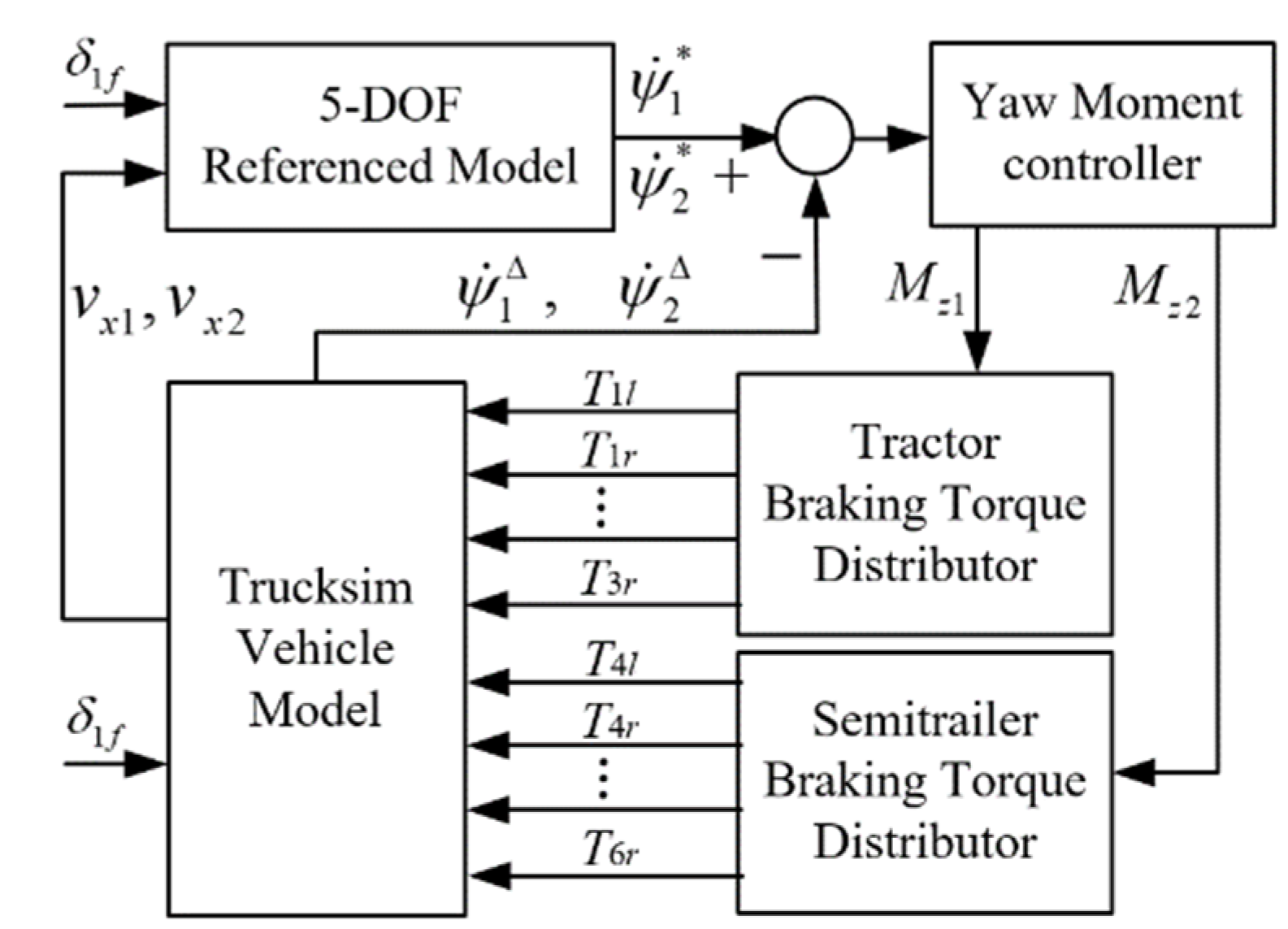
3. Stability Control System Design

As is known that the yaw rate is a crucial state parameter for vehicle stability and can be measured directly by sensors. Therefore, the yaw rates of the tractor-semitrailer are considered as the referenced responses, and the motions of the tractor and semitrailer are controlled individually to follow the referenced responses. The stability control system of the tractor-semitrailer shown in Figure 2 include three control layers. The upper layer is the determination of the referenced responses of the tractor-semitrailer based on the 5-DOF referenced model and the adhesion limit of the tire force. The middle layer is the yaw moment controller, which aims at judging the stability of the tractor-semitrailer and then determining the yaw moments Mz1 and Mz2. The yaw moments Mz1 and Mz2 will be exerted on the tractor and semitrailer, respectively. The lower layer is the braking torque distributor, which decides the target wheels to be braked and distributes the braking torques on the target wheels to achieve the required yaw moments. With this closed-loop feedback control, the state adjustment and stability control of the tractor-semitrailer under the lane-change maneuvers at high speed can be realized.
In Figure 2, δ1f is the front wheel steering angle of the tractor, ψ ˙ 1 and ψ ˙ 2 are the referenced yaw rates of the tractor and semitrailer, ψ ˙ 1 Δ and ψ ˙ 2 Δ are the actual yaw rates of the tractor and semitrailer, Til, Tir (i = 1, 2, 3, 4, 5, 6) are the braking torques acting on the left and right wheels of the axles from the first to the sixth axle.

3.1. Referenced Responses

When the tractor-semitrailer is in a steady state, the derivative of the state variable equals zero, namely X = 0. Substituting it into Equation (9), the steady-state responses of the tractor-semitrailer can be obtained.
X = A 1 B δ 1 f
The expected yaw rates of the tractor and semitrailer ψ ˙ 1 and ψ ˙ 2 can be described as:
{ ψ ˙ 1 = [ 0 1 0 0 0 0 0 0 ] X ψ ˙ 2 = [ 0 0 0 0 0 1 0 0 ] X
The effect of the road adhesion coefficient is not taken into account in the 5-DOF yaw-roll vehicle model. However, the expected yaw rates shown in Equation (12) may not be obtained under the condition of low adhesion. Therefore, the steady-state responses of the yaw rates should satisfy the Equation (13).
ψ ˙ 1 , 2 | μ g v x 1 , x 2 |
where μ is the road adhesion coefficient, g is the gravitational acceleration, and vx1,x2 is the longitudinal velocities of the tractor and semitrailer, respectively.
Therefore, the referenced yaw rates of the tractor and semitrailer ψ ˙ 1 and ψ ˙ 2 can be written as Equation (14).
{ ψ ˙ 1 = min { | ψ ˙ 1 | , | μ g v x 1 | } sgn ( ψ ˙ 1 ) ψ ˙ 2 = min { | ψ ˙ 2 | , | μ g v x 2 | } sgn ( ψ ˙ 2 )
To compare the influence of yaw moment controller on the lateral stability of the tractor-semitrailer under the lane-change maneuvers at high speed, two yaw moment controllers of the proportional-derivative (PD) control and the model predictive control (MPC) are designed.

3.2. Proportional-Derivative Control

A feedback proportional-derivative (PD) controller, which neglects the integral term of a typical PID controller [30,31], is used here to keep the tractor-semitrailer’s yaw rates following the referenced yaw rates. The yaw rate deviations Δ ψ ˙ 1 and Δ ψ ˙ 2 between the actual yaw rates and the referenced yaw rates are taken as the inputs of the PD controller. The yaw moments Mz1 and Mz2 exerted on the tractor and semitrailer can be expressed as [32]:
{ M z 1 = K p 1 Δ ψ ˙ 1 ( t ) + K d 1 d Δ ψ ˙ 1 ( t ) / d t M z 2 = K p 2 Δ ψ ˙ 2 ( t ) + K d 2 d Δ ψ ˙ 2 ( t ) / d t
where Δ ψ ˙ 1 = | ψ ˙ 1 Δ | | ψ ˙ 1 | and Δ ψ ˙ 2 = | ψ ˙ 2 Δ | | ψ ˙ 2 | , the Kpi and Kdi (i = 1, 2) are control gains of the proportional item and the derivative item. PD gains are obtained by trial-and-error method.
As there is always an error between the linear 5-DOF yaw-roll vehicle model and the TruckSim vehicle model, the deviations between the actual yaw rates and the referenced yaw rates cannot equal zero. Therefore, the phenomenon of frequent braking will occur. It is well known that frequent braking may lead to the shortened life of brakes and nervous drivers. To avoid this phenomenon the deviations of the yaw rates should be constrained in a range listed in Equation (16) [33].
{ | Δ ψ ˙ 1 | c y 1 | ψ ˙ 1 | | Δ ψ ˙ 2 | c y 2 | ψ ˙ 2 |
where cy1 and cy2 are the coefficients used to determine whether to implement the yaw moment control for the tractor and the semitrailer. The values of the coefficients cy1 and cy2 are empirical values determined by the system parameters of the tractor-semitrailer. When the yaw rate deviations conform to Equation (16), the yaw moment controller will operate and output required yaw moments to the braking torque distributors.

3.3. Model Predictive Control

The model predictive control is extensively employed for vehicle dynamics control [21,22,23,24,25]. The essence of MPC is to solve an open-loop optimal control problem. At every sampling moment, according to the current measurement information, solve the finite time domain open-loop optimization problem, send the control data to the controlled object which obtained from the current state and enter the next sampling time. Repeat the above process and update the optimization problem with new measured values, and then solve it again, so as to form a closed-loop control system. Through rolling optimization, MPC can minimize the deviation between the predicted future output and the expected output of the controlled object, and compensate the error caused by system instability.
To realize the stable lane-change maneuver of the tractor-semitrailer at high speed, u is selected as the control variable, u = [Mz1 Mz2]T. The state-space equation of the tractor-semitrailer with MPC can be expressed as [33]:
{ x ˙ = A a x + B b δ 1 f + B 1 u y = C x
where Aa = M−1A and Bb = M−1B, the matrices M, A and B are presented in Appendix B, and B1 is the control variable coefficient matrix which can be written as:
B 1 = M 1 [ 1 0 0 0 0 0 0 1 0 0 0 0 0 0 0 0 ] T
The coefficient matrix C can be written as:
C = [ 1   0   0   0   0   0   0   0 0   1   0   0   0   0   0   0 0   0   0   0   1   0   0   0 0   0   0   0   0   1   0   0 ]
Since the MPC system generally adopts the discrete state space model, the continuous state space model shown in Equation (17) needs to be discretized, and the discrete state space equation can be written as [24]:
{ x ( k + 1 ) = A a , d x ( k ) + B b , d δ ( k ) + B 1 , d u ( k ) y ( k + 1 ) = C d x ( k + 1 )
where x(k) and x(k + 1) are the states of the system at the last sampling time and the current sampling time, respectively; y(k + 1) is the output of the system at the current sampling time; Aa,d, Bb,d, B1,d, and Cd are the parameter matrices of the discrete system state space. The above parameter matrices can be expressed as Formula (21) and the symbol Ts is the sampling time of the system [24].
{ A a , d = e A T s B b , d = 0 T s e A τ d τ B b B 1 , d = 0 T s e A τ d τ B 1 C d = C
The objective of the MPC is to ensure the deviations between the actual yaw rates and the referenced yaw rates are as small as possible. To provide the smooth operation of the controller and impose certain constraints on the control increment, the objective control function is defined as [24]:
J = i = 1 N p y ( k + i | k ) y ( k + i | k ) Q 2 + i = 1 N c 1 Δ u ( k + i | k ) R 2 + ρ ε 2
where y(k + i|k) is the predicted value at the k + i sampling time based on the output at the k sampling time, y*(k + i|k) is the expected reference value, and [y(k + i|k)−y*(k + i|k)] reflects the tracking capability of the system; △u(k + i|k) is the control increment of the system at the sampling time k + i, reflecting the operation stability of the system; Q and R are weight matrixes, reflecting the relative importance of tracking error and control action; ρ is the weight coefficient; ε is the relaxation factor in ensuring that a feasible solution can be obtained for each optimization; Np and Nc are the prediction time domain and control time domain of the control system, respectively.
To make the tractor-semitrailer change lanes smoothly at high speed, the MPC is required not to output excessive yaw moment at one time, and at the same time limit the yaw moment increment. Therefore, the saturation characteristic is introduced in Formula (23) to constrain the yaw moment and its increment [24].
{ u min u ( k + i ) u max Δ u min Δ u ( k + i ) Δ u max i = 0 , 1 , , N c 1
where umin and umax are the thresholds of the yaw moment, △umin and △umax are the thresholds of the increment of the yaw moment.
The following constraint shown in Formula (24) needs to be added to the system output [24].
y min y ( k + i ) y max ( i = 0 , 1 , , N p )
where ymin and ymax are the thresholds of the yaw rate of the tractor-semitrailer.
By substituting Formulas (23) and (24) into Formula (22), the optimization problem is transformed into a quadratic programming problem.

3.4. Braking Torque Distributor

The braking torque distributors are used to determine the target wheels to be braked and distribute the braking torques on the target wheels to achieve yaw moments. Selection of the target wheels to be braked involves two aspects: one is the yaw motion of the tractor-semitrailer when braking different wheels; the other is the direction of the yaw moment to be provided, which is mainly determined by the actual and referenced yaw rates. For the tractor-semitrailer the specific selection rules of the target wheels to be braked are shown in Table 1 and Table 2. In the tables, “−” and “+” represent the direction of the yaw motion, and “−” represents the counterclockwise and “+” represents the clockwise; | ψ ˙ 1 Δ |−| ψ ˙ 1 | and | ψ ˙ 2 Δ |−| ψ ˙ 2 | are used to compare the actual yaw rates with the referenced yaw rates, and “>0” means to cause a yaw motion in clockwise and “<0” means to cause a yaw motion in counterclockwise; L1, L2, and L3 and R1, R2, and R3 represent the left and right wheels on the three axles of the tractor, respectively; L4, L5, and L6 and R4, R5, and R6 refer to the left and right wheels on the three axles of the semitrailer, respectively; “\” indicates the selection of target braking wheels has no relation with the yaw rate deviation.
After the target wheel is determined, the braking torque applied to the target wheels can be calculated according to the yaw moment. Because the front wheel angle of the tractor will change during braking, if the target braking wheel is the front wheel, the influence of the front wheel angle should be considered when calculating the braking torque. To simplify the calculation, except the front axle it is assumed that the braking torque on the left and right wheels of the same axle is the same.
The braking torque on the left and right wheels on the front axle of the tractor can be written as [23]:
{ T 1 l = M z 1 r 1 / ( a 1 sin δ 1 f + 0.5 B 1 cos δ 1 f ) T 1 r = M z 1 r 1 / ( a 1 sin δ 1 f + 0.5 B 1 cos δ 1 f )
The braking torque on the left and right wheels on the intermediate and rear axles of the tractor can be written as:
T 2 l = T 2 r = ( M z 1 r 2 / 3 ) / ( B 2 / 2 )
The braking torque on the left and right wheels on each axle of the semitrailer can be written as:
T 3 l = T 3 r = ( M z 2 r 3 / 3 ) / ( B 3 / 2 )
In the above formula, r1, r2, and r3 are the rolling radii of the wheels on the front axle of the tractor, the wheels on the intermediate and rear axles of the tractor, and the wheels of the semitrailer, respectively; B1, B2, and B3 are the track widths between the left and right wheels on the tractor front axle, on the tractor intermediate and rear axles, and on the semitrailer three axles, respectively.

4. Simulation Results

In this section, the effectiveness of the proposed control strategy and the influence of the PD and MPC yaw moment controllers on the lateral stability of the tractor-semitrailer are investigated under the high-speed SLC and DLC maneuvers. The nominal values of the system parameters for the tractor-semitrailer are given in Appendix A.
The simulation platform of the tractor-semitrailer is established based on the software of TruckSim 8.1 and Matlab/Simulink 2018b. The proposed controller is designed by the Simulink blocks and interfaced with TruckSim. The actual yaw rates of the tractor-semitrailer output from TruckSim are input to Simulink, and compared with the referenced yaw rates. The required braking torque on target wheels of the tractor-semitrailer is calculated in Simulink and fed to the TruckSim. The yaw moment control of the tractor-semitrailer is formed in a closed-loop manner and implemented by numerical simulation. The adhesion coefficient of the simulation road is 0.85, the simulation time step is set to 0.001 s, and the simulation time is 12 s and 15 s for the SLC and DLC maneuvers, respectively. To simplify the expression, PD case is used to denote the tractor-semitrailer with PD controller, and MPC case is used to denote the tractor-semitrailer with MPC.

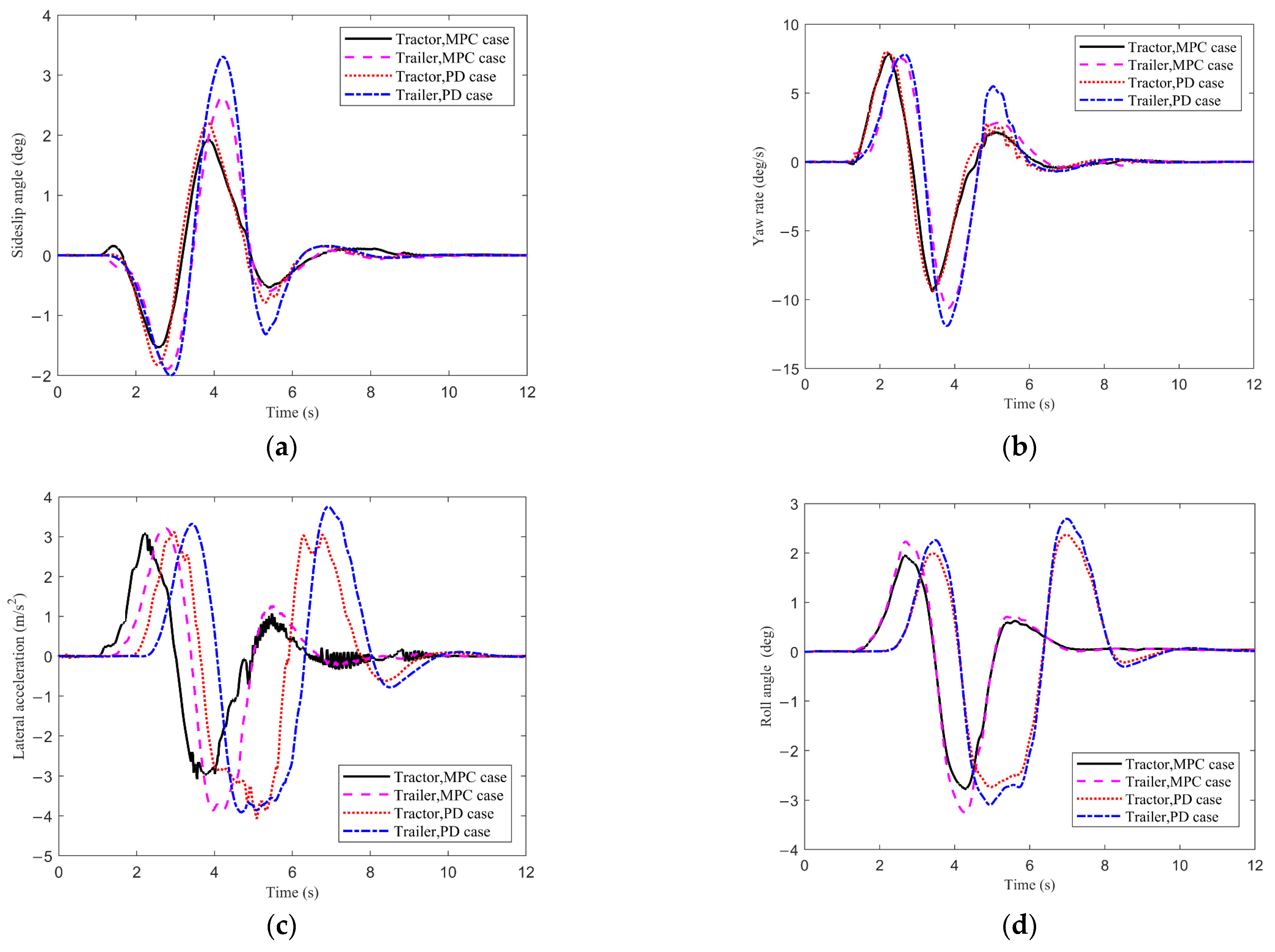
4.1. Single Lane-Change (SLC) Maneuver

The SLC maneuver of the tractor-semitrailer is performed at the speed of 110 km/h. Four dynamic responses are used to describe the lateral stability of the tractor-semitrailer at high speed, such as the sideslip angles and lateral accelerations at the CG of the tractor and trailer, the yaw rates and roll angles of the tractor and trailer. Figure 3 demonstrates the four dynamic responses of the tractor-semitrailer with the PD or MPC yaw moment controller. Figure 3 shows that except for the roll angle, the dynamic responses of the trailer all lag behind those of the tractor. From Figure 3a it can be seen that for the PD case, the peak sideslip angles at the CG of the tractor and trailer are 2.2° and 3.3°, respectively; for the MPC case, the corresponding values of the tractor and trailer are 1.9° and 2.6°, respectively. Compared with the PD case, the peak sideslip angles at the CG of the tractor and trailer with MPC are decreased by 13.6% and 21.2%, respectively. Figure 3b demonstrates the time history of yaw rates. From the figure, it can be seen that the second peak yaw rate of the MPC case is significantly less than that of the PD case. It means the MPC can control the yaw motion of the trailer faster. Figure 3c,d show the time history of lateral acceleration and roll angle of the tractor-semitrailer. It is obvious that the second peak lateral acceleration and roll angle of the tractor-semitrailer with MPC are significantly less than those of the tractor-semitrailer with PD controller. Compared with the PD case, for the MPC case the second peak lateral acceleration for the tractor and trailer are, respectively, decreased by 65.2% and 66.4%, and those of the roll angle for the tractor and trailer are decreased by 73.8% and 72.5%, respectively. Furthermore, compared with the PD case, the tractor-semitrailer with MPC has shorter dynamic responding time and can reach a new steady state after a shorter time.
To sum up, it can be seen that under the SLC maneuver the tractor-semitrailer controlled by the MPC has better lateral dynamic performance than that controlled by the PD controller. The tractor-semitrailer with MPC has lower peak values of dynamic responses, shorter dynamic responding time, and can reach a new steady state after a shorter time.

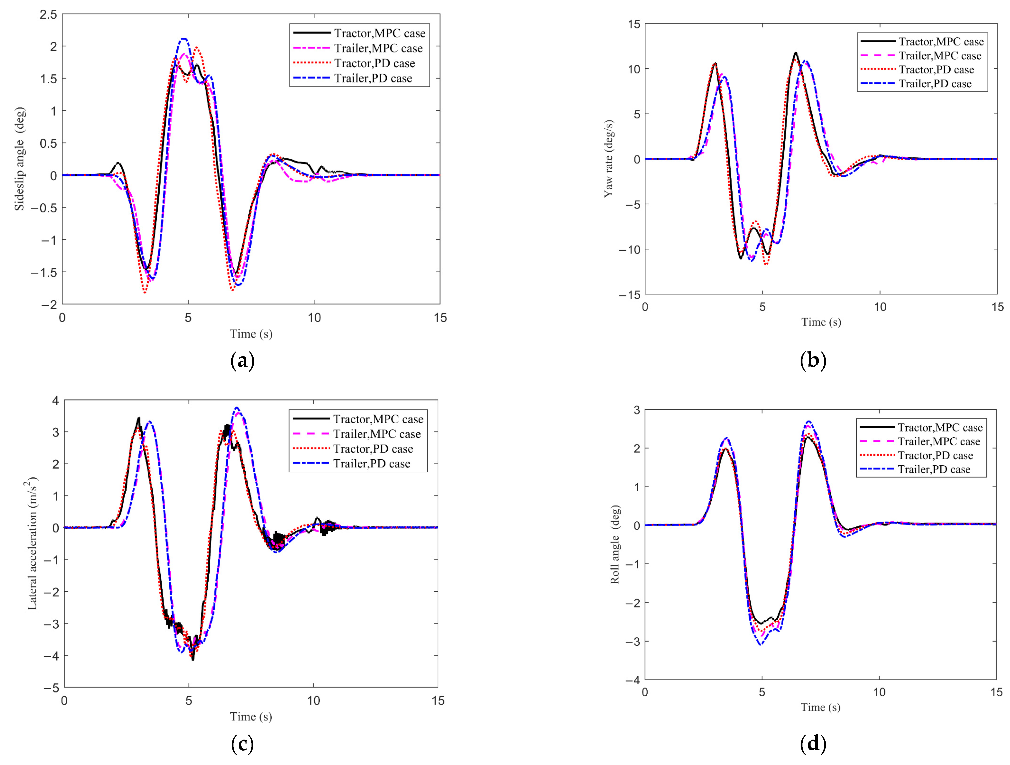
4.2. Double Lane-Change (DLC) Maneuver

For the tractor-semitrailer, the high-speed DLC maneuver is a hazardous operating condition which is very prone to transient rollover accidents. In this subsection, the influence of the PD and MPC yaw moment controllers on the lateral stability of the tractor-semitrailer is investigated under the DLC maneuvers at the speed of 88 km/h. Four dynamic responses of the tractor-semitrailer under the DLC maneuver are shown in Figure 4. It is easy to see that the yaw rate and lateral acceleration of the trailer lag behind those of the tractor to some extent in terms of responding time. Figure 4a shows that for the PD case, the peak sideslip angles at the CG of the tractor and trailer are 1.9° and 2.1°, respectively; for the MPC case, the corresponding values of the tractor and trailer are 1.7° and 1.8°, respectively. Compared with the PD case the peak sideslip angles at the CG of the tractor and trailer with MPC are decreased by 10.5% and 14.3%, respectively. Figure 4b,c show that the yaw moment controller has no obvious influence on the yaw rate and the lateral acceleration of the tractor-semitrailer. In Figure 4c, the lateral acceleration curve of the tractor partially behaves jagged, which means that the tractor has a slight shimmy under the DLC maneuver. Figure 4d shows the roll angles of the tractor and trailer under the DLC maneuver. As is shown in the figure, for the PD case, the peak roll angles of the tractor and trailer are 2.7° and 3.1°, respectively; for the MPC case, the corresponding peak values are 2.5° and 2.9°, respectively. Compared with the PD case, the peak roll angles of the tractor and trailer with MPC are decreased by 7.4% and 6.5%, respectively.

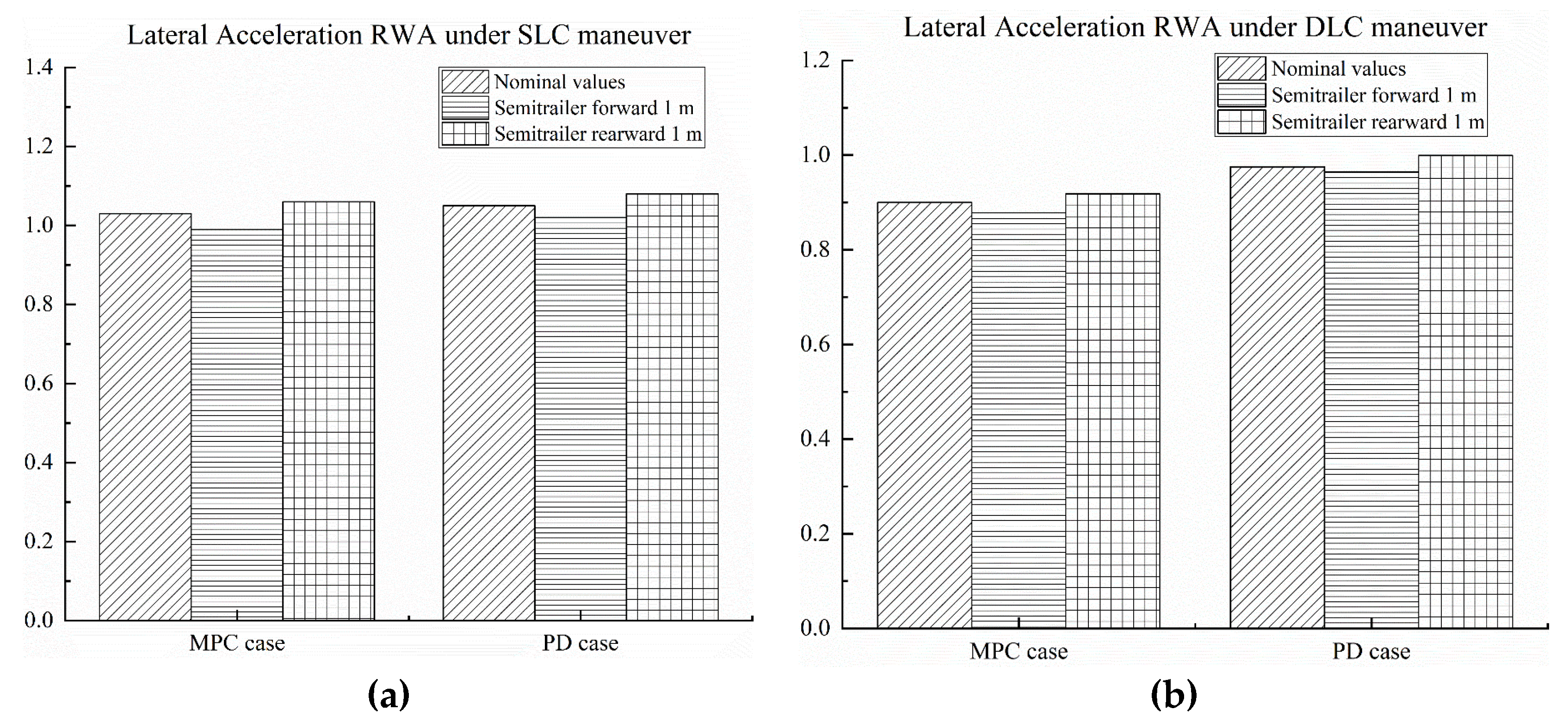
5. Controller Sensitivity to Parameter Uncertainties

For further investigation of the controller robustness, its sensitivity to vehicle parameter uncertainties is investigated under the SLC and DLC maneuvers. In this study, the considered vehicle parameters for this purpose are the semitrailer sprung mass, semitrailer CG longitudinal position, and semitrailer CG vertical position.
Rearward amplification (RWA) ratio is a very important performance measure for high-speed lateral stability of tractor-semitrailers, which is defined as the ratio of the peak lateral acceleration at the rearmost trailer’s CG to that of the tractor in an obstacle avoidance lane-change maneuvers [9]. The lower the RWA, the better the lateral stability. Therefore, in this study lateral acceleration RWA is used as the stability evaluation index to investigate the sensitivity of the controllers to the parameter uncertainties.
The semitrailer sprung mass is varied in the controller independently by ±20% from the nominal values. Figure 5 illustrates the effect of uncertainties in semitrailer sprung mass on the MPC and PD controller performance and the obtained lateral acceleration RWA. It can be seen that the MPC and PD controllers are quite robust with respect to the semitrailer sprung mass under two test environments of the SLC and DLC maneuvers.
Considering the wheelbase length of the semitrailer, the considered amount of uncertainty for the longitudinal position of the semitrailer CG is 1 m. The results of analysis of the controller sensitivity to uncertainties in the semitrailer CG longitudinal position are shown in Figure 6. It can be seen that the MPC and PD controllers can exhibit good robustness to the semitrailer CG longitudinal position. The estimating semitrailer CG longitudinal position further rearward than the nominal position slightly reduces the controller effectiveness.
The amount of uncertainty for the vertical position of the semitrailer CG is 0.5 m considering the restrictions of relevant regulations on the height of loaded cargo. The results of analysis of the controller sensitivity to uncertainties in the semitrailer CG vertical position are shown in Figure 7. It can be seen that the controller performance does not vary considerably, which means the MPC and PD controllers are robust with respect to the semitrailer CG vertical position. The estimating semitrailer CG vertical position further upward than the nominal position slightly reduces the controller effectiveness.

6. Conclusions

The high-speed lateral stability control strategy based on the additional yaw moment is proposed, and the effectiveness of the designed controller and its influence on the lateral stability of the tractor-semitrailer are investigated. Main conclusions are drawn as follows.
(1)
The proposed high-speed lateral stability control strategy is feasible, which is based on the additional yaw moment caused by differential braking and can ensure the tractor-semitrailer to safely perform the SLC maneuver at 110 km/h and DLC maneuver at 88 km/h.
(2)
The yaw moment controller has significant influence on the lateral dynamic performance of the tractor-semitrailer, and the influence under the SLC maneuver is more notable than that under the DLC maneuver. Compared with the PD case, under the SLC maneuver the tractor-semitrailer with MPC has lower peak values of dynamic responses, shorter dynamic responding time, and can reach a new steady state after a shorter time. Under the DLC maneuver, the MPC yaw moment controller can reduce the peak values of the dynamic responses to a certain extent, but it has no obvious advantage over the PD controller in terms of the responding time.
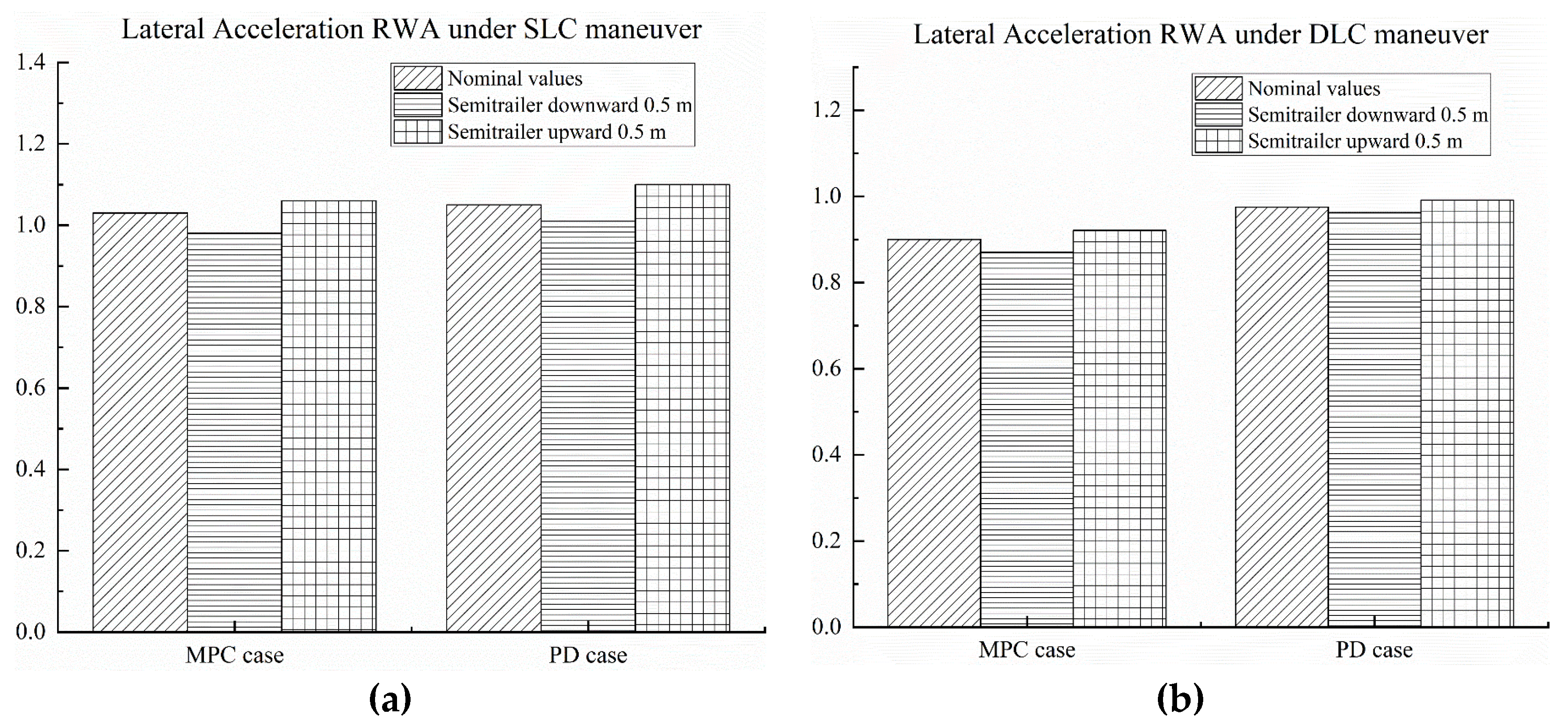
(3)
The MPC and PD controllers exhibit good robustness to the considered vehicle parameter uncertainties. The robustness of the two controllers under the DLC maneuver is better than that under the SLC maneuver. Compared with the PD controller, the MPC can make the tractor-semitrailer obtain lower lateral acceleration RWA and better stability.

Author Contributions

Conceptualization, X.X. and H.C.; methodology, X.X.; validation, H.C.; investigation, X.X. and H.C.; data curation, H.C.; writing—original draft preparation, H.C.; writing—review and editing, X.X.; funding acquisition, X.X. All authors have read and agreed to the published version of the manuscript.

Funding

This work was funded in part by National Natural Science Foundation of China, grant number 51605228 and Six Talent Peaks Project in Jiangsu Province, grant number JXQC-025.

Institutional Review Board Statement

Not applicable.

Informed Consent Statement

Not applicable.

Data Availability Statement

Not applicable.

Conflicts of Interest

The authors declare no conflict of interest.

Appendix A

Table A1. Description and Nominal Values of the Parameters for the Tractor-Semitrailer Dynamic Model.
SymbolDescriptionNominal Value
m1Total mass of the tractor6360 kg
m1sSprung mass of the tractor4455 kg
m2Total mass of the semitrailer25,910 kg
m2sSprung mass of the semitrailer23,840 kg
a1Distance between the center of gravity (CG) of the tractor and its front axle2.35 m
b1Distance between the CG of the tractor and its intermediate axle1.15 m
c1Distance between the hitch point and the intermediate axle of the tractor0.64 m
d1Distance between the hitch point and the rear axle of the tractor0.64 m
a2Distance between the hitch point and the CG of the semitrailer5.61 m
b2Distance between the CG of the semitrailer and its front axle1.11 m
c2Distance between the front axle and the intermediate axle of the semitrailer1.20 m
d2Distance between the rear axle and the intermediate axle of the semitrailer1.20 m
r1Rolling radius of the wheels on the front axle of the tractor0.52 m
r2Rolling radius of the wheels on the intermediate and rear axles of the tractor0.52 m
r3Rolling radius of the wheels of the semitrailer0.52 m
B1Track width between the front left and right wheels of the tractor2.03 m
B2Track width between the left and right wheels of the tractor intermediate and rear axles1.86 m
B3Track width between the left and right wheels of the semitrailer1.86 m
h1sHeight of the CG of the sprung mass for the tractor1.18 m
h2sHeight of the CG of the sprung mass for the semitrailer2.19 m
h1rHeight of the roll center of the sprung mass for the tractor0.61 m
h2rHeight of the roll center of the sprung mass for the semitrailer1.02 m
hpHeight of the hitch point1.10 m
I1zzYaw moment of inertia of the whole mass of the tractor45,075.9 kg m2
I1sxxRoll moment of inertia of the sprung mass of the tractor2283.9 kg m2
I1sxzRoll–yaw product of inertia of the sprung mass of the tractor1626 kg m2
I2zzYaw moment of inertia of the whole mass of the semitrailer285,516 kg m2
I2sxxRoll moment of inertia of the sprung mass of the semitrailer21,802.3 kg m2
I2sxzRoll-yaw product of inertia of the sprung mass of the semitrailer0 kg m2
K1*Roll stiffness of the tractor1,631,140 N m/rad
K2*Roll stiffness of the semitrailer4,265,880 N m/rad
K12Roll stiffness of the articulation joint between the tractor and semitrailer5,729,578 N m/rad
C1*Roll damping of the tractor’s suspension48,150 N m s/rad
C2*Roll damping of the semitrailer’s suspension45,000 N m s/rad
k1fTire cornering stiffness of the front axle of the tractor−231,430 N/rad
k1mTire cornering stiffness of the intermediate axle of the tractor−520,000 N/rad
k1rTire cornering stiffness of the rear axle of the tractor−520,000 N/rad
k2fTire cornering stiffness of the front axle of the semitrailer−553,000 N/rad
k2mTire cornering stiffness of the intermediate axle of the semitrailer−553,000 N/rad
k2rTire cornering stiffness of the rear axle of the semitrailer−553,000 N/rad
F1f/F1m/F1rLateral forces subjected by the front, intermediate and rear axles of the tractor
F2f/F2m/F2rLateral forces subjected by the front, intermediate and rear axles of the semitrailer
α1f/α1m/α1rTire slip angles for the front, intermediate and rear axles of the tractor
α2f/α2m/α2rTire slip angles for the front, intermediate and rear axles of the semitrailer
β1/β2Sideslip angles at CG of the tractor and semitrailer
ψ ˙ 1 / ψ ˙ 2 Yaw rates of the tractor and semitrailer
ϕ1/ϕ2Roll angles of the sprung mass of the tractor and semitrailer
δ1fFront wheel steering angle of the tractor
h1cr/h2crDistances between the hitch point and roll center of the sprung mass for the tractor and semitrailer
h1sr/h2srDistances between the CG and roll center of the sprung mass for the tractor and semitrailer
F1oy/F2oyLateral reaction forces at the hitch point for the tractor and semitrailer
vx1/vx2Longitudinal velocities of the tractor and semitrailer
v1/v2Forward velocities of the tractor and semitrailer

Appendix B. Relevant Matrices Definition

In Equation (9), the matrices M, A, and B are defined as:
M = [ m 11 m 12 0 m 14 0 0 0 0 m 21 m 22 m 23 m 24 0 0 0 0 0 0 1 0 0 0 0 0 0 0 0 0 m 45 m 46 0 m 48 0 0 0 0 m 55 m 56 m 57 m 58 0 0 0 0 0 0 1 0 m 71 0 0 m 74 m 75 0 0 m 78 1 m 82 0 m 84 1 m 86 0 m 88 ] ,   A = [ a 11 a 12 0 0 0 0 0 0 a 21 a 22 a 23 0 0 0 a 27 0 0 0 0 1 0 0 0 0 0 0 0 0 a 45 a 46 0 0 0 0 a 53 0 a 55 a 56 a 57 0 0 0 0 0 0 0 0 1 a 71 a 72 0 0 a 75 a 76 0 0 0 1 0 0 0 1 0 0 ]
B = [ ( a 1 + b 1 + c 1 ) k 1 f h 1 c r k 1 f 0 0 0 0 k 1 f 0 ] T
In matrix M, the relevant elements are given as:
m 11 = m 1 v x 1 ( b 1 + c 1 ) m 12 = I 1 z z ,
m 14 = [ m 1 s h 1 s r ( b 1 + c 1 ) + I 1 s x z ] , m 21 = m 1 v x 1 h 1 c r m 1 s h 1 s r v x 1 ,
m 22 = I 1 s x z , m 23 = C 1 ,
m 24 = m 1 s h 1 s r h 1 c r + I 1 s x x 2 m 1 s h 1 s r 2 , m 45 = m 2 v x 2 a 2 ,
m 46 = I 2 z z , m 48 = m 2 s h 2 s r a 2 + I 2 s x z ,
m 55 = m 2 v x 2 h 2 c r m 2 s h 2 s r v x 2 , m 56 = I 2 s x z ,
m 57 = C 2 , m 58 = m 2 s h 2 s r h 2 c r + I 2 s x x + 2 m 2 s h 2 s r 2 ,
m 71 = m 1 v x 1 , m 74 = m 1 s h 1 s r ,
m 75 = m 2 v x 2 , m 78 = m 2 s h 2 s r ,
m 82 = ( b 1 + c 1 ) / v x 1 , m 84 = h 1 c r / v x 1 ,
m 86 = a 2 / v x 2 , m 88 = h 2 c r / v x 2 .
In matrix A, the relevant elements are given as:
a 11 = ( a 1 + b 1 + c 1 ) k 1 f + c 1 k 1 m d 1 k 1 r , a 21 = h 1 c r ( k 1 f + k 1 m + k 1 r ) ,
a 12 = [ a 1 ( a 1 + b 1 + c 1 ) k 1 f b 1 c 1 k 1 m + d 1 ( b 1 + c 1 + d 1 ) k r ] / v x 1 m 1 v 1 ( b 1 + c 1 ) ,
a 22 = h 1 c r [ a 1 k 1 f b 1 k 1 m ( b 1 + c 1 + d 1 ) k 1 r ] / v x 1 m 1 v 1 h 1 c r + m 1 s v 1 h 1 s r ,
a 23 = m 1 s g h 1 s r K 1 K 12 , a 27 = K 12 ,
a 45 = ( a 2 + b 2 ) k 2 f + ( a 2 + b 2 + c 2 ) k 2 m + ( a 2 + b 2 + c 2 + d 2 ) k 2 r ,
a 46 = [ b 2 ( a 2 + b 2 ) k 2 f ( b 2 + c 2 ) ( a 2 + b 2 + c 2 ) k 2 m ( b 2 + c 2 + d 2 ) ( a 2 + b 2 + c 2 + d 2 ) k 2 r ] / v x 2 m 2 v 2 a 2 ,
a 53 = K 12 , a 55 = h 2 c r ( k 2 f + k 2 m + k 2 r ) ,
a 56 = h 2 c r [ b 2 k 2 f ( b 2 + c 2 ) k 2 m ( b 2 + c 2 + d 2 ) k 2 r ) ] / v x 2 m 2 v 2 h 2 c r + m 2 s v 2 h 2 s r ,
a 57 = m 2 s g h 2 s r K 1 K 12 , a 71 = k 1 f + k 1 m + k 1 r ,
a 72 = [ a 1 k 1 f b 1 k 1 m ( b 1 + c 1 + d 1 ) k 1 r ] / v x 1 m 1 v x 1 , a 75 = k 2 f + k 2 m + k 2 r ,
a 76 = [ b 2 k 2 f ( b 2 + c 2 ) k 2 m ( b 2 + c 2 + d 2 ) k 2 r ) ] / v x 2 m 2 v x 2 .

References

  1. Xu, X.; Zhang, L.; Jiang, Y.; Chen, N. Active control on path following and lateral stability for truck-trailer combinations. Arab. J. Sci. Eng. 2019, 44, 1365–1377. [Google Scholar] [CrossRef]
  2. Li, Z.; Yao, J.; Xu, Y. Controlling the vertical shift of an isolated body based on the vibration of nonlinear systems with asymmetric damping forces. Meccanica 2022, 57, 1173–1191. [Google Scholar] [CrossRef]
  3. Li, Z.; Yao, J.; Xu, Y.; Jia, Y. Analysis of a novel methodology for shifting an isolated body based on nonlinear system vibration. J. Vib. Control 2022. [Google Scholar] [CrossRef]
  4. Li, B.; Zeng, L. Fractional calculus control of road vehicle lateral stability after a tire blowout. Mechanika 2021, 27, 475–482. [Google Scholar] [CrossRef]
  5. Zhang, R.; Peng, T.; Lv, Z.; Qiu, Z. Bifurcation and robust control analysis to tractor-semitrailer with interference on rainy slippery road. Future Gener. Comput. Syst. 2020, 107, 126–143. [Google Scholar] [CrossRef]
  6. Sun, H.; Yang, L.; Chen, Y.; Zhang, X. Controlling tractor-semitrailer vehicles in automated highway systems: Adaptive robust and Lyapunov minimax approach. Asian J. Control 2021, 23, 2642–2656. [Google Scholar] [CrossRef]
  7. Harun, M.H.; Hudha, K.; Samin, P.M.; Abu Bakar, S.A.; Amer, N.H.; Abd Kadir, Z. A modified odenthal rollover index algorithm for tractor-semitrailer using steering and vehicle speed inputs. Int. J. Heavy Veh. Syst. 2021, 28, 563–584. [Google Scholar] [CrossRef]
  8. Tian, J.; Ding, J.; Tai, Y.; Chen, N. Hierarchical control of nonlinear active four-wheel-steering vehicles. Energies 2018, 11, 2930. [Google Scholar] [CrossRef] [Green Version]
  9. Ni, Z.; He, Y. Design and validation of a robust active trailer steering system for multi-trailer articulated heavy vehicles. Veh. Syst. Dyn. 2019, 57, 1545–1571. [Google Scholar] [CrossRef]
  10. Tian, J.; Zeng, Q.K.; Wang, P.; Wang, X.Q. Active steering control based on preview theory for articulated heavy vehicles. PLoS ONE 2021, 16, e0252098. [Google Scholar] [CrossRef]
  11. Zong, C.; Zhu, T.; Wang, C.; Liu, H. Multi-objective stability control algorithm of heavy tractor semi-trailer based on differential braking. Chin. J. Mech. Eng. 2012, 25, 88–97. [Google Scholar] [CrossRef]
  12. Termous, H.; Shraim, H.; Talj, R.; Francis, C.; Charara, A. Coordinated control strategies for active steering, differential braking and active suspension for vehicle stability, handling and safety improvement. Veh. Syst. Dyn. 2018, 57, 1494–1529. [Google Scholar] [CrossRef]
  13. Tian, J.; Tong, J.; Luo, S. Differential Steering Control of Four-Wheel Independent-Drive Electric Vehicles. Energies 2018, 11, 2892. [Google Scholar] [CrossRef] [Green Version]
  14. Li, B.; Rakheja, S.; Feng, Y. Enhancement of vehicle stability through integration of direct yaw moment and active rear steering. Proc. Inst. Mech. Eng. Part D J. Automob. Eng. 2016, 230, 830–840. [Google Scholar] [CrossRef]
  15. Elhemly, M.A.; Fayed, M.A.; Elmaihy, A.A. Tractor-semitrailer jackknifing elimination using semitrailer differential braking technique. Int. J. Heavy Veh. Syst. 2013, 20, 19–34. [Google Scholar] [CrossRef]
  16. Lee, E. Design Optimization of Active Trailer Differential Braking Systems for Car-Trailer Combinations; University of Ontario Institute of Technology: Oshawa, ON, Canda, 2017. [Google Scholar]
  17. Cui, Q.; Ding, R.; Wu, X.; Zhou, B. A new strategy for rear-end collision avoidance via autonomous steering and differential braking in highway driving. Veh. Syst. Dyn. 2020, 58, 955–986. [Google Scholar] [CrossRef]
  18. Li, H.; Zhao, Y.; Lin, F.; Xiao, Z. Integrated yaw and rollover control based on differential braking for off-road vehicles with mechanical elastic wheel. J. Cent. South Univ. 2019, 26, 2354–2367. [Google Scholar] [CrossRef]
  19. Zhang, B.; Zong, C.; Chen, G.; Huang, Y.; Xu, T. A novel integrated stability control based on differential braking and active steering for four-axle trucks. Chin. J. Mech. Eng. 2019, 32, 1–21. [Google Scholar] [CrossRef]
  20. Bai, Z.; Lu, Y.; Li, Y. Method of improving lateral stability by using additional yaw moment of semi-Trailer. Energies 2020, 13, 6317. [Google Scholar] [CrossRef]
  21. Li, L.; Lu, Y.; Wang, R.; Chen, J. A three-dimensional dynamics control framework of vehicle lateral stability and rollover prevention via active braking with MPC. IEEE Trans. Ind. Electron. 2017, 64, 3389–3401. [Google Scholar] [CrossRef]
  22. Ataei, M.; Khajepour, A.; Jeon, S. Model predictive control for integrated lateral stability, traction/braking control, and rollover prevention of electric vehicles. Veh. Syst. Dyn. 2020, 58, 49–73. [Google Scholar] [CrossRef]
  23. Choi, M.; Choi, S.B. MPC for vehicle lateral stability via differential braking and active front steering considering practical aspects. Proc. Inst. Mech. Eng. Part D J. Automob. Eng. 2016, 230, 459–469. [Google Scholar] [CrossRef]
  24. Jalali, M.; Khosravani, S.; Khajepour, A.; Chen, S.K. Model predictive control of vehicle stability using coordinated active steering and differential brakes. Mechatronics 2017, 48, 30–41. [Google Scholar] [CrossRef]
  25. Abroshan, M.; Hajiloo, R.; Hashemi, E.; Khajepour, A. Model predictive-based tractor-trailer stabilization using differential braking with experimental verification. Veh. Syst. Dyn. 2021, 59, 1190–1213. [Google Scholar] [CrossRef]
  26. Haung, H.H.; Yedavalli, R.K.; Guenther, D.A. Active roll control for rollover prevention of heavy articulated vehicles with multipe-rollover-index minimization. Veh. Syst. Dyn. 2012, 50, 471–493. [Google Scholar] [CrossRef]
  27. Jeong, D.; Ko, G.; Choi, S.B. Estimation of sideslip angle and cornering stiffness of an articulated vehicle using a constrained lateral dynamics model. Mechatronics 2022, 85, 102810. [Google Scholar] [CrossRef]
  28. Liu, Z.; Hu, K.; Chung, K.W. Nonlinear analysis of a closed-loop tractor-semitrailer vehicle system with time delay. Mech. Syst. Signal Pr. 2016, 76–77, 696–711. [Google Scholar] [CrossRef]
  29. Ding, X.; He, Y.; Ren, J.; Sun, T. A comparative study of control algorithms for active trailer steering systems of articulated heavy vehicles. In Proceedings of the American Control Conference Fairmont Queen Elizabeth, Montreal, QU, Canada, 27–29 June 2012. [Google Scholar]
  30. Cheng, Z.; Lu, Z. Research on load disturbance based variable speed PID control and a novel denoising method based effect evaluation of HST for agricultural machinery. Agriculture 2021, 11, 960. [Google Scholar] [CrossRef]
  31. Tai, Y.; Li, P.; Zheng, Y.; Tian, J. Entropy generation and thermoelastic damping in the in-plane vibration of microring resonators. Entropy 2019, 21, 631. [Google Scholar] [CrossRef] [Green Version]
  32. Liu, D.; Huang, S.; Wu, S.; Fu, X. Direct yaw-moment control of electric vehicle with in-wheel motor drive system. Int. J. Auto. Technol. 2020, 21, 1013–1028. [Google Scholar] [CrossRef]
  33. Yang, X. Optimal reconfiguration control of the yaw stability of the tractor-semitrailer vehicle. Math. Probl. Eng. 2012, 2012, 602502. [Google Scholar] [CrossRef]
Figure 1. Schematic representation of the tractor-semitrailer model. (a) Side view; (b) top view; (c) rear view.
Machines 10 00716 g001
Figure 2. Block diagram of the stability control system.
Machines 10 00716 g002
Figure 3. Comparison of dynamic responses for the tractor-semitrailer with MPC and PD controller under the SLC maneuver: (a) sideslip angle; (b) yaw rate; (c) lateral acceleration; (d) roll angle.
Machines 10 00716 g003
Figure 4. Comparison of dynamic responses for the tractor-semitrailer with MPC and PD controller under the DLC maneuver: (a) sideslip angle; (b) yaw rate; (c) lateral acceleration; (d) roll angle.
Machines 10 00716 g004
Figure 5. Effect of semitrailer sprung mass uncertainties on obtained lateral acceleration RWA for MPC case and PD case: (a) under the SLC maneuver; (b) under the DLC maneuver.
Machines 10 00716 g005
Figure 6. Effect of semitrailer CG longitudinal position uncertainties on obtained lateral acceleration RWA for MPC case and PD case: (a) under the SLC maneuver; (b) under the DLC maneuver.
Machines 10 00716 g006
Figure 7. Effect of semitrailer CG vertical position uncertainties on obtained lateral acceleration RWA for MPC case and PD case: (a) under the SLC maneuver; (b) under the DLC maneuver.
Machines 10 00716 g007
Table 1. Selection rules for the target braking wheels of the tractor.
Referenced Yaw Rate
( ψ ˙ 1 )
Actual Yaw Rate
( ψ ˙ 1 Δ )
Yaw Rate Deviation
( | ψ ˙ 1 Δ | | ψ ˙ 1 | )
Direction of Mz1Target Braking Wheel
>0+R1
<0L2, L3
++>0L1
++<0+R2, R3
+\L1
\+R1
0+\L1
0\+R1
0\L2, L3
+0\+R2, R3
Table 2. Selection rules for the target braking wheels of the semitrailer.
Referenced Yaw Rate
( ψ ˙ 2 )
Actual Yaw Rate
( ψ ˙ 2 Δ )
Yaw Rate Deviation
( | ψ ˙ 2 Δ | | ψ ˙ 2 | )
Direction of Mz2Target Braking Wheel
++R4, R5, R6
L4, L5, L6
+++L4, L5, L6
+++R4, R5, R6
+\L4, L5, L6
\+R4, R5, R6
0+\L4, L5, L6
0\+R4, R5, R6
0\L4, L5, L6
+0\+R4, R5, R6
Publisher’s Note: MDPI stays neutral with regard to jurisdictional claims in published maps and institutional affiliations.

