Article

Curvature Correction of a Notched Continuum Robot Based on a Static Model Considering Large Deformation and Friction Effect

1
School of Mechanical Engineering, Shandong University, Jinan 250061, China
2
Key Laboratory of High Efficiency and Clean Mechanical Manufacture of Ministry of Education, Shandong University, Jinan 250061, China
3
Department of Control Science and Engineering, Tongji University, Shanghai 200092, China
4
Beijing Advanced Innovation Center for Intelligent Robots and Systems, Beijing Institute of Technology, Beijing 100081, China
*
Author to whom correspondence should be addressed.
These authors contributed equally to this work.
Machines 2022, 10(9), 778; https://doi.org/10.3390/machines10090778
Submission received: 6 August 2022 / Revised: 28 August 2022 / Accepted: 3 September 2022 / Published: 7 September 2022

Abstract

:
Continuum robots are often used as wrist joints in medical robots because of their high dexterity and flexibility. Especially, the notched continuum robot (NCR) is used in the miniaturized wristed surgical robot. The Piecewise Constant Curvature (PCC) assumption is often used in the design of NCR. However, due to the friction effect, ideal PCC is difficult to achieve. Static analysis is a necessary means to correct the curvature of NCR. The static modeling of NCR is often based on the theory of small deformation. However, this cannot obtain accurate solutions at large bending angles. In this paper, a static model of a triangular-notched continuum robot is proposed. It presents a curvature correction method of NCR, considering large deformation. In addition, the friction effect is considered in the correction of PCC. The static model is derived from the end notch. Based on the Coulomb friction model, the recurrence relationship of the force on the cable is obtained. Then the elliptic integral solution corresponding to the large deformation assumption is calculated. The deformation parameters of the NCR are obtained by numerical iteration. Finally, the capability and validity of the static model proposed in this paper are verified in the experiment. This paper is of great significance for establishing an accurate static model for curvature correction and design of the notched continuum robot.

1. Introduction

Biology has inspired researchers in many ways [1], most notably in continuum robotics. Snakes [2], elephant trunks [3,4], tongues [5], tails [6], and octopus tentacles [7] show incredible capabilities for locomotion, manipulation, and dexterity in cluttered environments, which has inspired researchers to work toward recreating their abilities [8]. Benefiting from the extreme dexterity and flexibility, continuum robots are increasingly used in minimally invasive surgery (MIS) [9]. Especially, in single port access surgery and natural orifices transluminal endoscopic surgery [10,11], continuum robots are often used in the wrist joints of the surgery system [12,13,14,15]. However, within the miniaturized wrist surgical instrument, notched continuum robotic wrists are an emerging area of research. York [16] et al. proposed a continuum robotic wrist with asymmetric notches. Kutzer [17] et al. designed a rectangular-notched continuum robot with an outer diameter of 5.99 mm for minimally invasive osteolysis clearance. Eastwood [18] et al. presented an asymmetric notched continuum surgical robotic wrist for neuroendoscopy. Francis [19] et al. proposed the miniaturized notched continuum robotic wrist for the da Vinci Surgical System.
Continuum robotic kinematics and mechanics modeling methods are determined by the basic transmission unit, which is divided into eleven types [20]. Among them, backbone CRs, soft-tube CRs and concentric-tube CRs are the most common. Most backbone CRs are made of NiTi and polypropylene [21], usually consisting of central backbones, cables and several rigid disks [22]. The soft-tube CRs always have silicone tubes, which are actuated by pneumatic and shape memory alloy [23]. Most concentric-tube CRs are made of superelastic Nitinol. The pre-curved concentric tubes are inserted inside each other and are translated and rotated axially about the concentric axis [24]. For notched continuum robots, which belong to the backbone CRs, a series of notches are processed in the robot’s backbone. The desired movement is achieved by the deformation of its material. Due to their easy manufacture and simple shape, notched continuum robots have rapidly become a rich and diverse area of research, and many structure designs and applications have been demonstrated [25]. However, these designs of the continuum robot are often based on Piecewise Constant Curvature (PCC), and the ideal PCC is difficult to implement [26]. Therefore, it is necessary to carry out piecewise constant curvature correction for NCR. On the other hand, the static modeling of NCR is mainly based on beam theory, currently. Du et al. [27] designed a cable-driven planar continuum robot and established a mechanical model for the multi-redundancy characteristics of V-notch structure based on Timoshenko beam theory. Gao et al. [28] proposed a mechanical model of continuum based on Cosserat rod theory and proposed a partition method describing DCM as a series of rigid and flexible links. The Cosserat rod theory is also applied to solve the deformation parameters of the continuum robots [29,30,31,32,33]. Finite element analysis was also used in the design of NCR structures [34]. The mechanical model of the continuum is given using the minimum energy method [22,35]. In addition, the piecewise constant curvature assumption is a standard solution premise [36,37,38] in the kinematics of continuous robotic arms. However, this assumption has its limitations. It often fails when considering large deformation, friction, internal forces, and external forces at the end [17]. These models perform very accurately in workspaces with small bends but do not reflect the actual situation at large deflections. The main reason for this is that there is no analytical solution when solving differential equations because of non-linear terms, which are pretty challenging. In most cases, to solve this quickly, the non-linear term is directly converted into a linear term by using the deformation coordination equation, which results in the principal error between the deformation parameters of the NCR and the theoretical results in actual conditions.
In this paper, a static model of a triangular-notched continuum robot considering large deformation is proposed. Meanwhile, the friction effect is considered in NCR’s piecewise constant curvature correction. The proposed model shows better controllability and accuracy than previous static models based on beam theory. The contributions are summarized as follows:
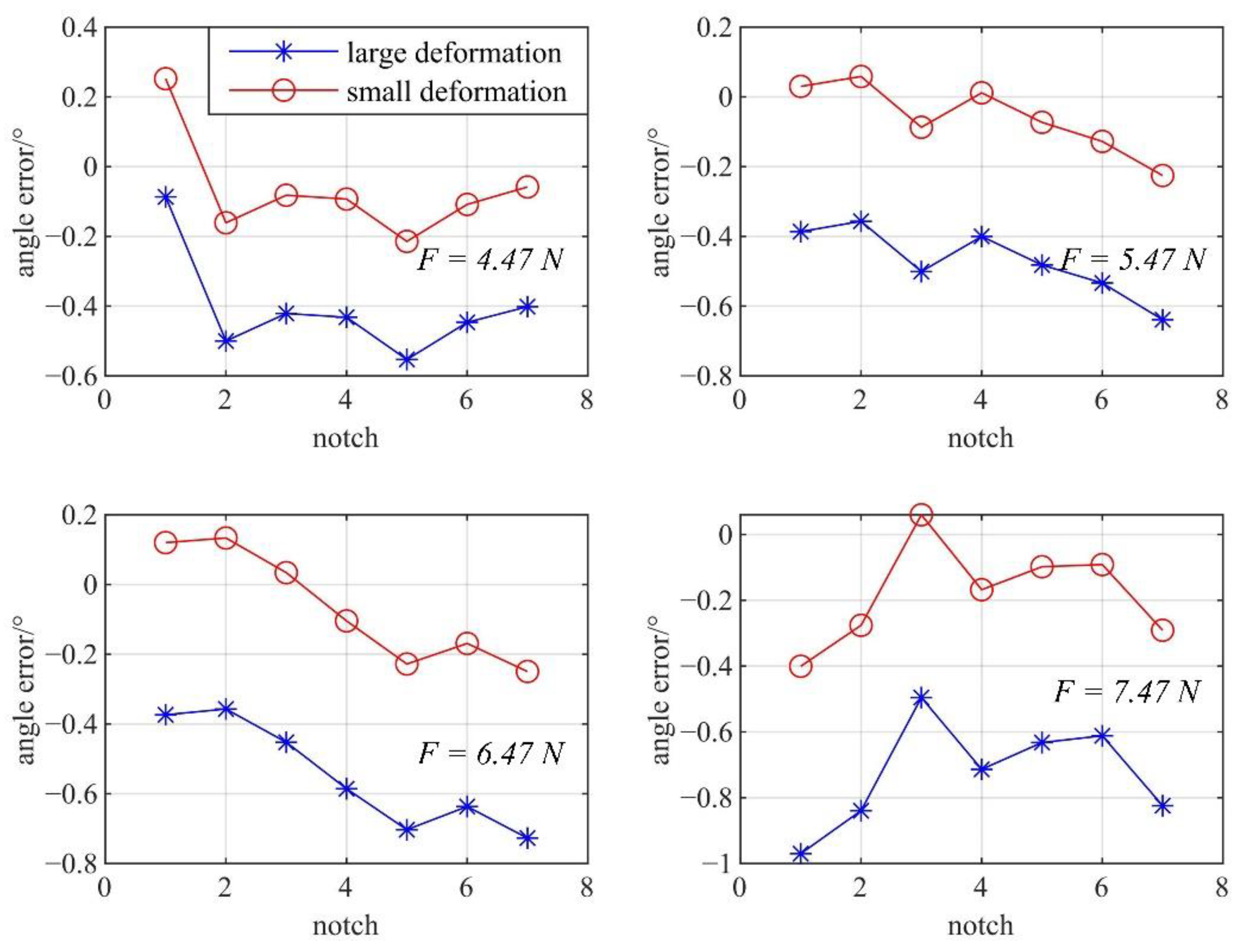
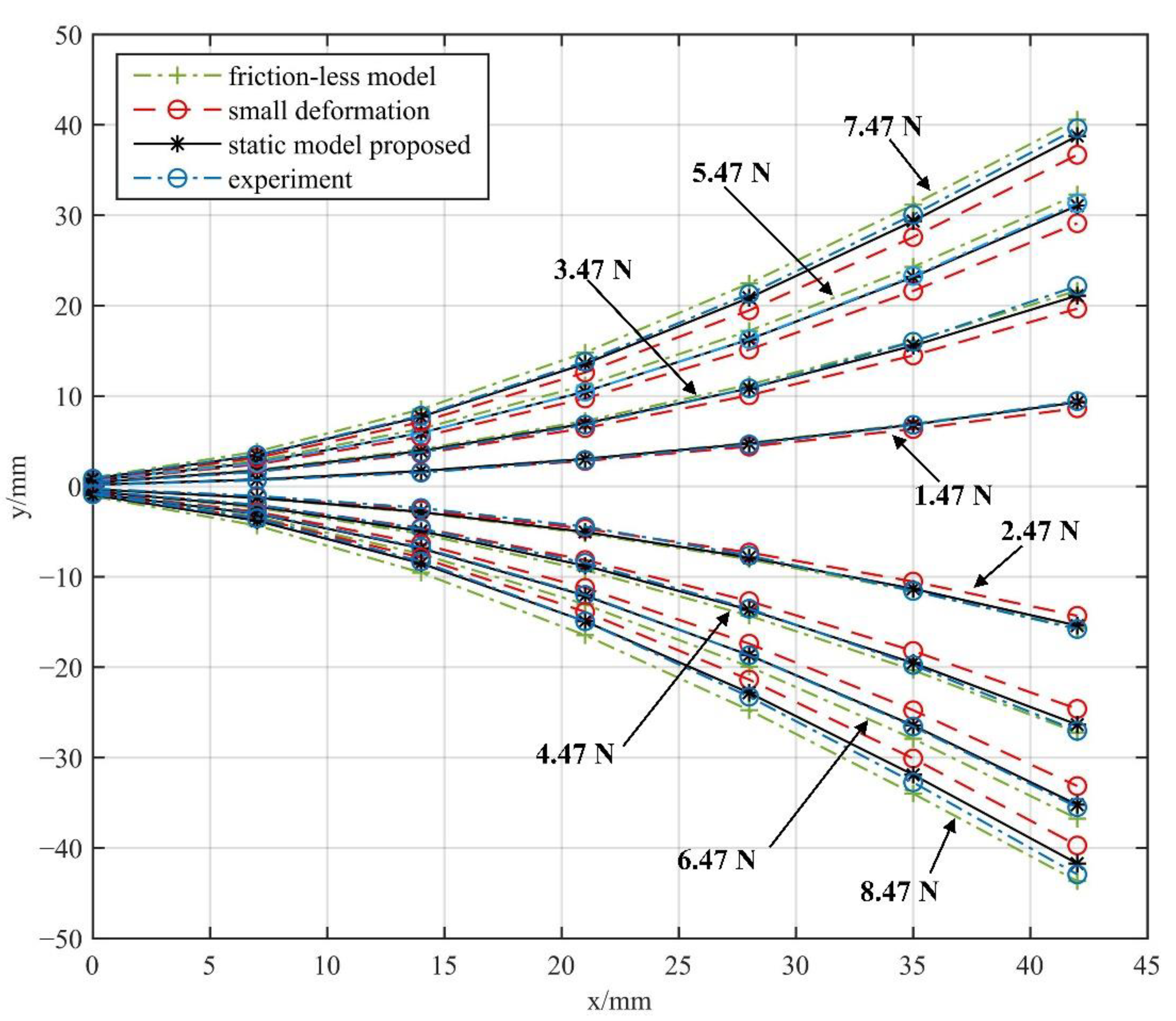
  • A static model of the NCR considering large deformation is proposed. The RMSE of the bending angle of every notch based on the large deformation assumption is 0.43°, significantly smaller than the small deformation assumption (1.47°).
  • Based on the static model, a piecewise constant curvature correction method of NCR is proposed. The exact single-notch deformation parameters are solved. And the method is validated by experiments and simulations.
  • The friction effect and the coupling effect of forces between multiple notches are considered in the model. The experimental results show that the error of the static model based on large deformation (2.4409°) is significantly smaller than that of the static models, which are based on small deformation and friction-less assumption (10.0972°, 5.1016°).
The structure of this paper is as follows: Section 2 describes the design of the NCR. Then, in Section 3, static modeling is carried out to show the process of obtaining deformation parameters and curvature correction of the triangular-notched continuum robot. Section 4 determines the friction coefficient between the cable and the continuum robot. In Section 5, the proposed static model is verified by experiments. Finally, in Section 6, some conclusions about this study are presented, and some directions for future research are provided.

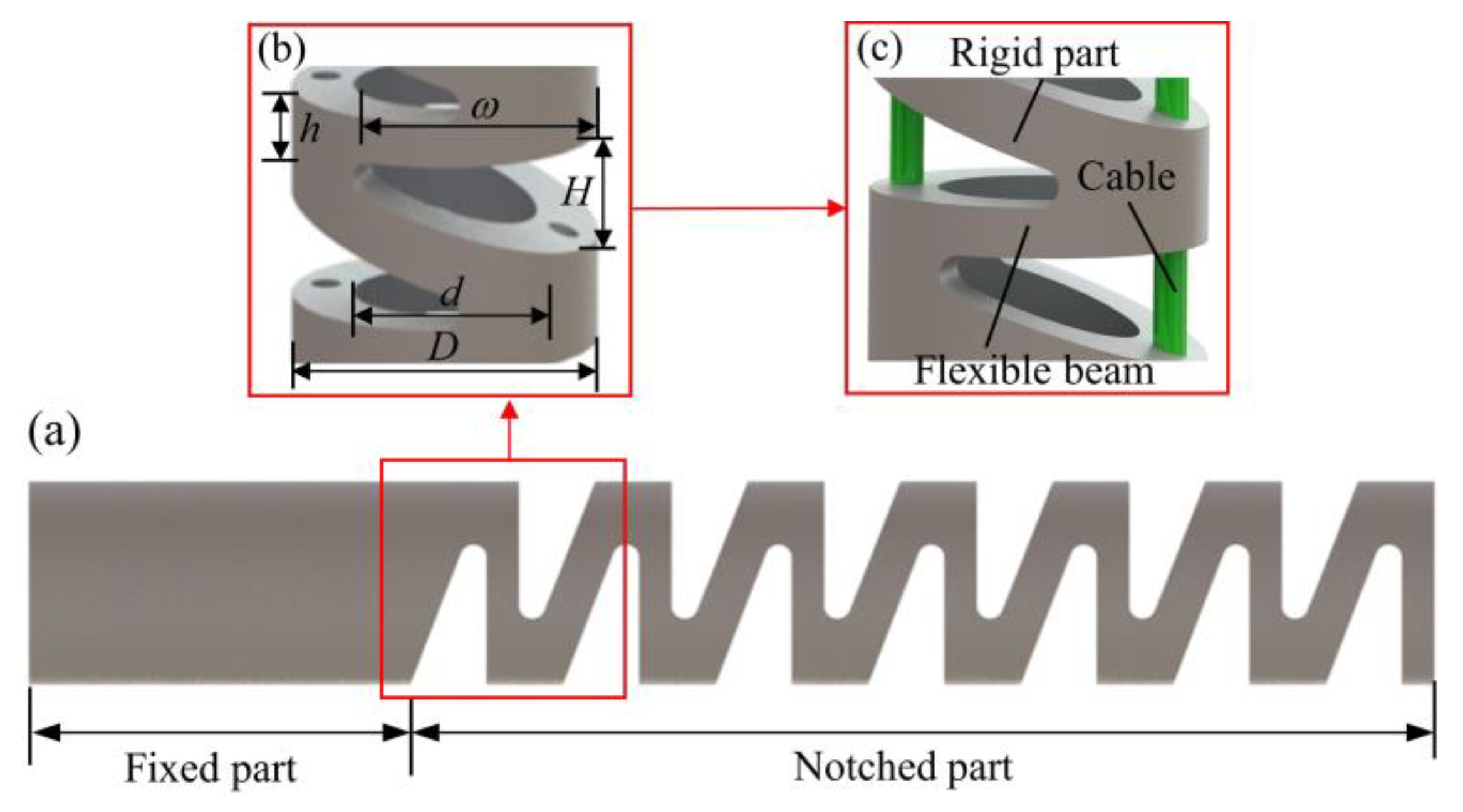
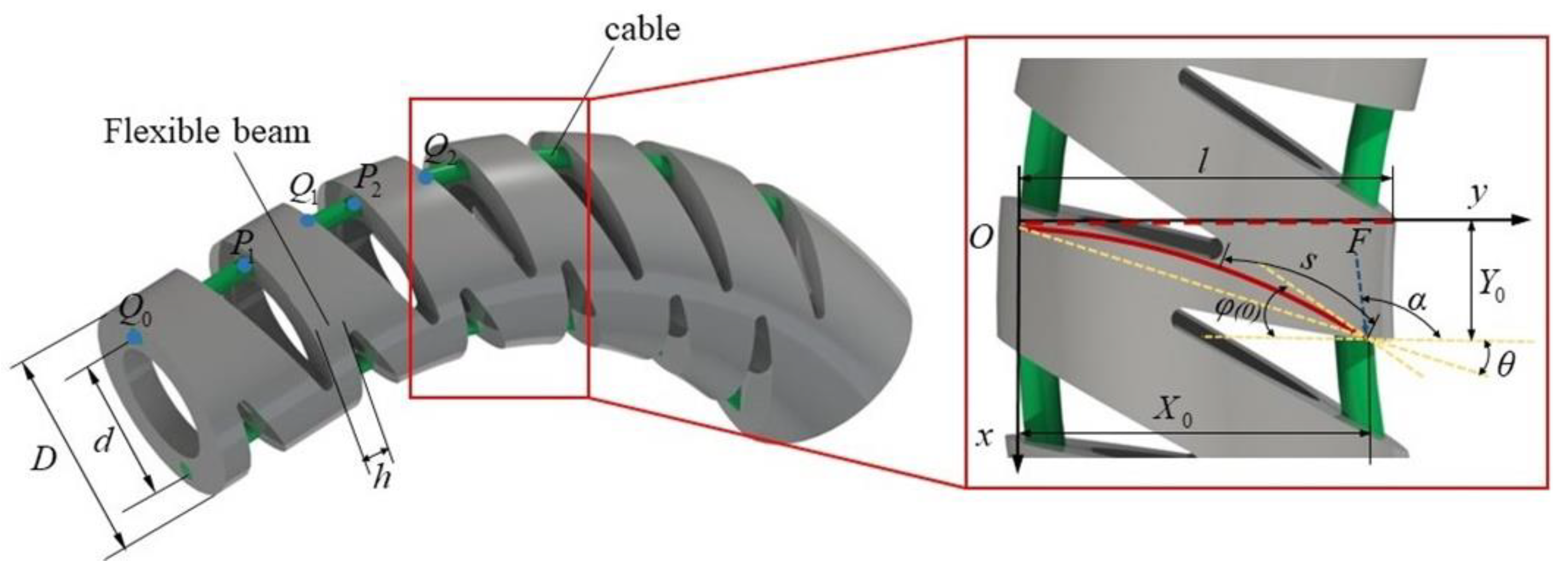
2. The Structure of the NCR

In the current research, NCR usually takes the form of a rectangular notch, which significantly reduces the rigidity of the material, large bending angle, and small bending radius. However, the backbone of the structure will produce large lateral displacement when it is deformed, which causes many uncertainties and difficulties in analysis and modeling.
Figure 1 shows the continuum robot with a triangular notch designed in this paper. The backbone of the NCR is manufactured by machining a series of triangular notches with height H and width ω. This unique structure can be regarded as a series of rigid parts connected with flexible beams with height h. Therefore, the structure can realize deflection by increasing or releasing the force in the cable. The parameters h, H, ω, D and d are the interval of the opposite side notch, the bottom edge length of the triangular notch, the depth of the triangular notch, the outside diameter, and the inside diameter of the NCR, respectively.
The proportion of the rigid part in the whole manipulator is related to the shape design, and size of the notches. The addition of rigid parts is bound to increase the system’s weight. However, the rigid parts can increase the stability and load capacity of the NCR. In addition, in analyzing the triangular-notched continuum robot designed in this paper, gravity has little influence on the construction of the static model.

3. Large Deformation Static Model

This paper made the following assumptions during the process of modeling:
  • Since the volume of the rigid part is much larger than that of the flexible part, the deformation of the rigid parts in the backbone can be ignored.
  • The NCR has two degrees of freedom: bending and rotation.
  • The friction between the cable and the NCR is obtained by the Coulomb model.

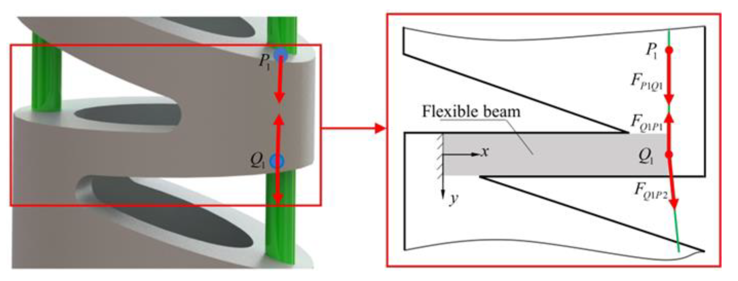
3.1. Static Modeling of a Single Notch

As seen in Figure 2, the flexible part of the continuum robot is a small hollow cylinder, which is regarded as an Euler-Bernoulli beam in the static model proposed in this paper. It is noted that the deformation of each triangular notch is mainly driven by the cable. However, the following assumptions need to be noticed: (1) The notches are all right triangles, which increases the lateral stiffness. The influence of lateral force on deformation is neglected. (2) Ignore the small deformation outside the deformation area. (3) Ignore the gravity effect of the joint in the NCR.
The static model is derived from the end notch of the continuum robot. From the end of the continuum robot, loads of each notch of the deformed beam are solved successively. The forces at the end of the robot are relatively simple. The cable is tightened and cannot move axially.
In the triangular-notched continuum robot, it is assumed that the cable is fixed at P1, Q1. The P1 is pulled only by force F P 1 Q 1 . At Q1, the deformed beam is subjected to forces F P 1 Q 1 and F Q 1 P 2 . The forces on the same cable are the same, i.e., F P 1 Q 1 = F Q 1 P 2 .
According to the force analysis, the resultant force of the first section of the deformed beam is:
F 1 = F Q 1 P 2 + F Q 1 P 1 + F P 1 Q 1 = F Q 1 P 2
Solving the load of any notch is similar to that of the end notch. However, it is noted that the influence of the upper notch cannot be neglected, which is more consistent with the actual situation. The static model established by this method will have higher precision.
The next notch is analyzed in Figure 3. The direction of the cable that is not fixed in the notched continuum robot may be changed. It is assumed that the cable is fixed at point P2, Q2. Forces F 1 and F Q 2 P 2 are applied at P2. Forces F Q 2 P 3 and F Q 2 P 2 are used in Q2. The resultant force of the second deformed beam can be expressed as:
F 2 = F Q 2 P 3 + F Q 2 P 2 + F P 2 Q 2 + F 1 + F 1 = F Q 2 P 3
Obviously, on the cable of notch i, the forces on the fixed point are force F Q i P i + 1 and F Q i P i . Considering the resultant force on the last cable is F i = F P i Q i and the direction is opposite F Q i P i , the end-load of the deformed beam (notch i) can be expressed as:
F i = F Q i P i + 1

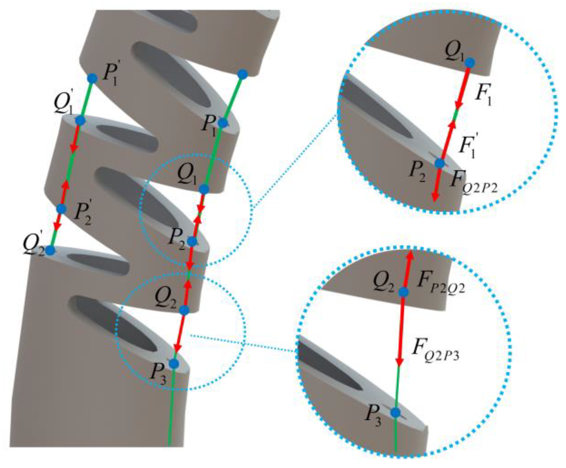
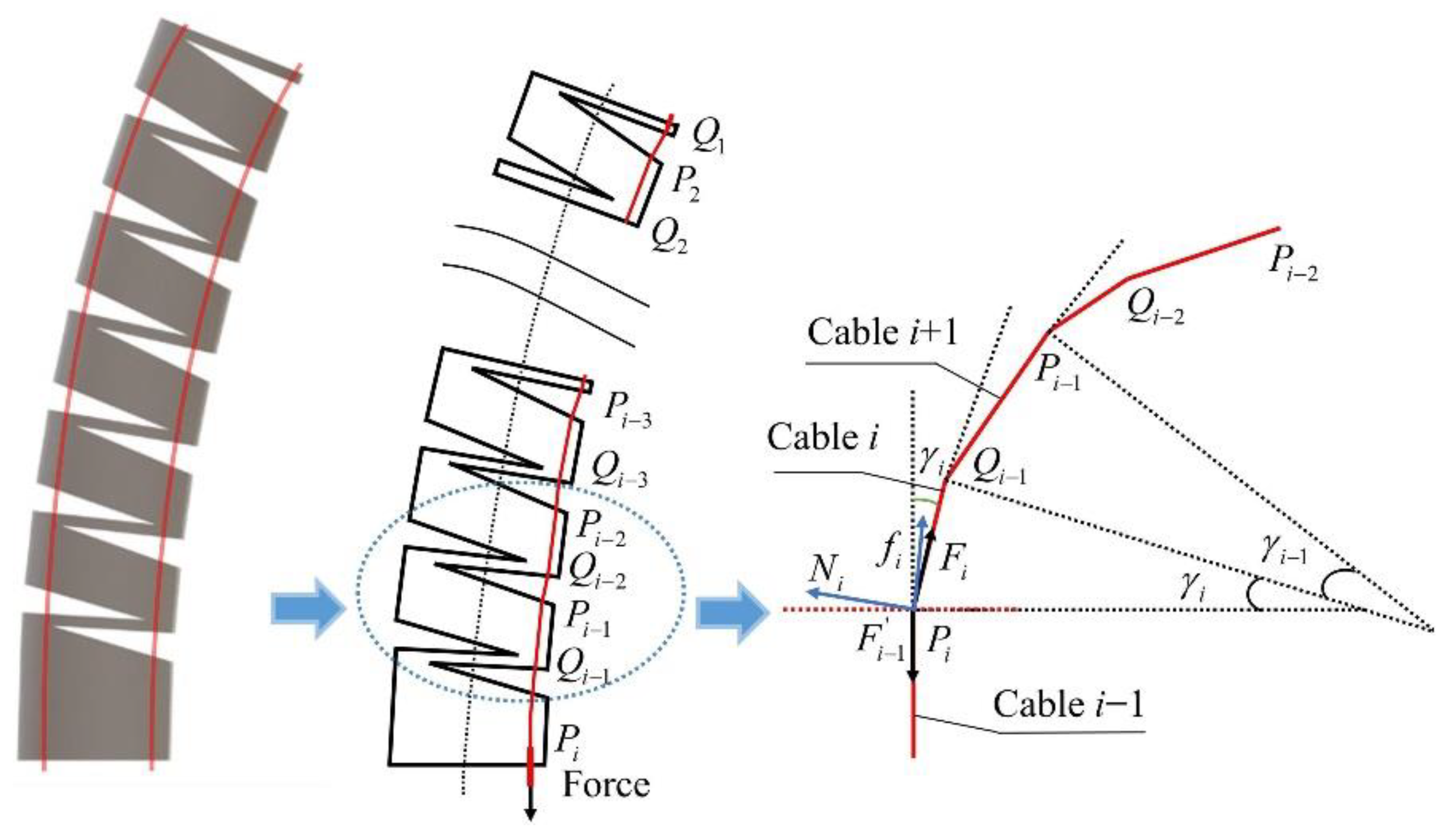
3.2. Solution of Load at Large Deformation Beam in Each Notch

According to the static model, the end-load of each flexible beam should be solved before obtaining the deformation parameters of each deformed beam.
In this paper, the NCR is driven by two cables. Its static model is different from the concentric tube robot. Due to the friction between the cables and the NCR, the assumption of piecewise constant curvature cannot be achieved but maintains the state of the piecewise straight line. Therefore, this part effectively analyzes and calculates the force of the cable based on the Coulomb friction model.
The force acting on the NCR in the external environment is complex. Considering only the force of the cable on end, the support force, and the friction force of the holes in the continuum robot, the gravity with less influence is neglected. The force acting on the cable is shown in Figure 4.
Several simplifications have been made in this paper when studying the friction between the NCR and the cable: (1) the cable always passes through the fixed points Pi and Qi on NCR. The friction between NCR and the cables occurs only at these fixed points. Fixed points are located at the edge of the rigid body. (2) The direction of the support force is outward along the angular bisector of the angle (obtuse angle) between the two ends of the cable, and the direction of the friction force is perpendicular to the direction of the support force.
Table 1 provides all the critical parameters in this analysis.
N i = N i f i = f i F i = F i
Through the force analysis of Pi the cable, it can be seen that the node is a group of equilibrium force systems under the action of F i , F i 1 , Ni and fi. According to the properties of the interaction force and equilibrium force system, Ni and fi’s action effect can be replaced equivalently. On the premise of meeting the above two conditions, combined with the force analysis diagram, we decompose the force in the direction of friction and support force to obtain the recurrence formula of cable tension:
f i + F i c o s γ i 2 = F i 1 c o s γ i 2
N i = F i s i n γ i 2 + F i 1 s i n γ i 2
μ N i = f i
The relationship between cable forces around the notch can be written as:
F i F i + 1 = cos γ i 2 μ sin γ i 2 cos γ i 2 + μ sin γ i 2

3.3. Elliptic Integral Based on Equivalent Large Deformation Beam

In the NCR presented in this paper, the flexible part connected to the rigid part undergoes large deformation at the free end under inclined concentrated load (see Figure 5). The differential equation representing this physical system is given. It is illustrated that although the equation is straightforward in appearance, it is quite challenging to solve due to the existence of non-linear terms. Because there is no analytical solution for the large deflection of the beam, the differential equation with nonlinear term must be solved. This problem involves geometric nonlinearity [39]. Therefore, it is difficult to accurately obtain the deformation parameters for the NCR, which is modeled based on beam theory.
The large deflection of the beam has become the subject of a considerable number of publications. Many scholars have given different analysis methods. Different numerical methods are used to solve the large deflection of a beam under a concentrated load [40,41,42,43]. With the continuous development of mathematical tools, this problem can also be solved by the elliptic integration method, which has the advantages of high accuracy, concise form, and high calculation efficiency [44,45,46]. Therefore, the deformation parameters of the equivalent beam based on this method are obtained. The relevant derivation process is given below.
As shown in Figure 5, the NCR is driven by two cables. The deformation part of the NCR is a small hollow cylinder, which is regarded as an Euler-Bernoulli beam. It has large deformation under the action of end load. h is the thickness of the deformed part, D is the continuum robot’s outer diameter, and d is the internal diameter.
Considering the beam’s actual deformation, the cable’s direction varies with the beam’s displacement. Therefore, the deformation solution of the beam under an inclined load is given. Figure 5 shows an equivalent beam of length l = D + d 2 with a concentrated load F applied at the beam’s free end. In Figure 5, X 0 and Y 0 are the horizontal and vertical displacements at the free end, respectively. φ ( 0 ) is the maximum slope of the beam. The origin of the Cartesian coordinate system is taken at the fixed end of the beam. The positive direction is shown in Figure 5. s is the arc length between any point on the beam and the endpoint. α is the angle between the load and the horizontal direction. θ is the angle between the line from the end of the equivalent beam to the fixed end and the horizontal direction.
According to Bernoulli–Euler bending the moment-curvature relationship:
κ = d φ d s = M ( s ) E I
(where κ is the curvature at any point of the beam, and M(s) is the bending moment). I is the moment of inertia of the beam cross-section about the neutral axis. It can also be written as:
E I d φ d s = F cos ( φ ( 0 ) α ) ( Y Y 0 ) F sin ( φ ( 0 ) α ) ( X X 0 )
φ and α are replaced with a new variable ω to obtain a single parameter second-order differential equation.
ω ( s ) = α + φ ( s ) φ ( 0 )
E I d 2 ω d s 2 + F sin ( ω ) = 0
Boundary conditions for the differential equations are ω ( L ) = α φ ( 0 ) and d ω d s ( 0 ) = 0 .
Integrating Equation (12) and applying the condition, one can obtain:
( d ω d s ) 2 | s = 4 F E I [ sin 2 ( ω 0 2 ) sin 2 ( ω 2 ) ]
Now write k 2 = s i n 2 ( ω 0 2 ) and introduce the variable γ .
sin ω 2 = k sin γ = sin ω 0 2 sin γ
Integrate Equation (13) and we can obtain:
s = 0 s d s = 1 F E I γ 1 γ 2 d γ 1 - k 2 sin 2 γ
Defining s ¯ = s L ; β = F l 2 2 E I ; F ( k , θ ) is elliptic integral. Equation (15) can be written as:
s = 1 2 β [ F ( k , γ 2 ) F ( k , γ 1 ) ]
Therefore, the mathematical relationship between beam deformation parameter at the free end and load is:
2 β = [ F ( k , γ 2 ) F ( k , π 2 ) ]
It is worth noting that the rotation angle φ is the angle between the tangent and horizontal direction of the deformed beam bending. Because it is increasing from the fixed end to the stressed end, it is not appropriate to express the deformation parameters of the whole deformed beam with the rotation angle of the end. In this paper, the deflection angle θ is used to describe the deformation state of the equivalent beam, that is, the arctangent of the end coordinate in the coordinate system. It is applied to the subsequent iteration and calculation.
X ( s ) = s L cos φ ( ε ) d ε
Y ( s ) = s L sin φ ( ε ) d ε
Thus, the deflection angle can be obtained θ = arctan Y 0 X 0 .

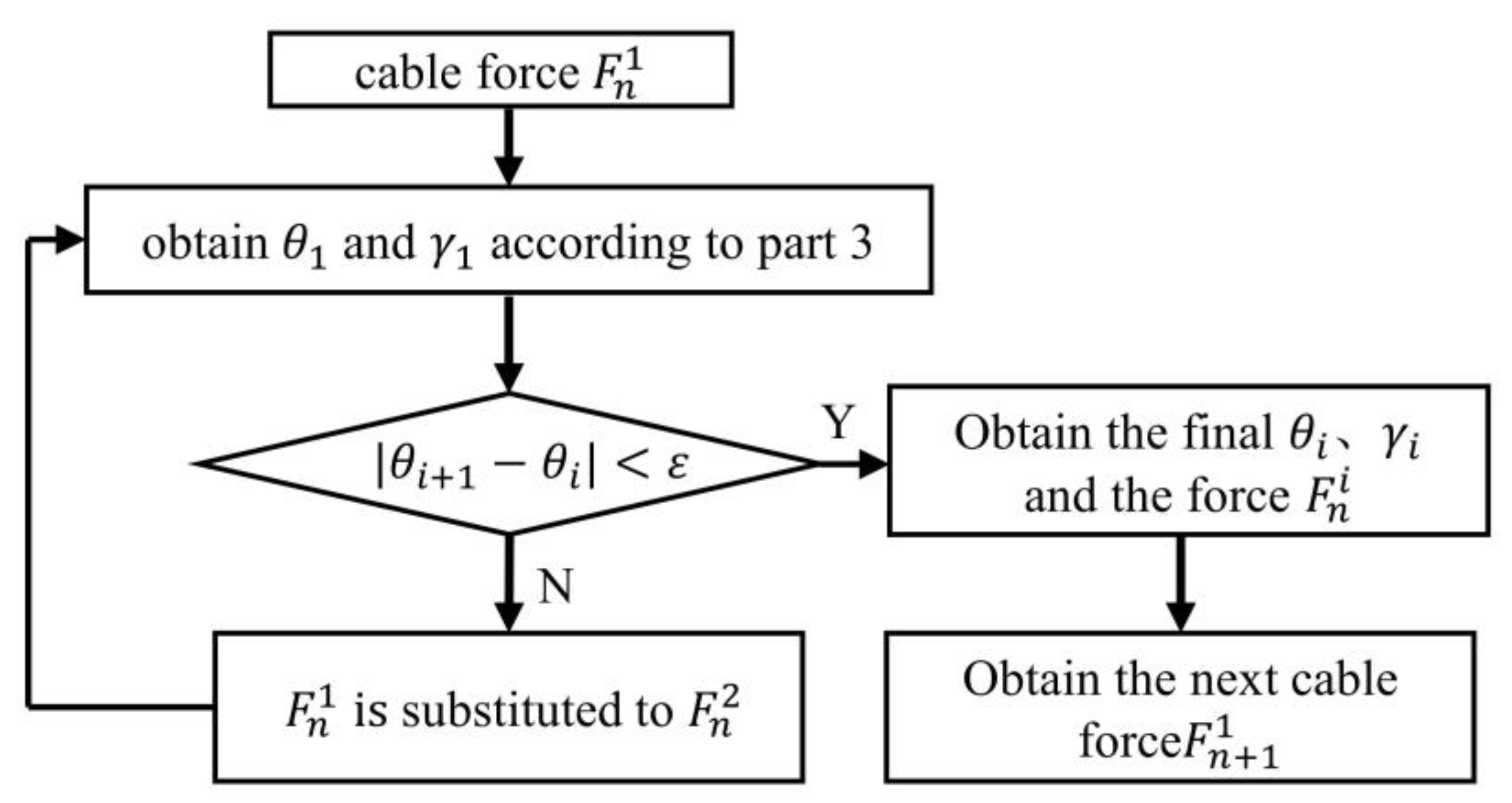
3.4. Curvature Correction and Solution of Deformation Parameters of the NCR

The solution of overall deformation parameters in the static model is essentially the solution of curvature of each segment. The deformation of NCR is often considered PCC. However, the ideal PCC is often difficult to achieve due to the friction effect. In engineering implementation, the deformation of NCR is usually non-constant curvature. Therefore, the piecewise constant curvature correction of NCR can be carried out by solving the deformation parameters of the static model considering the influence of friction.
An iterative approach can be used to solve the overall deformation parameters after deformation. During the process of continuous deformation from the initial state to the equilibrium state, the direction of load continuously changed with the bending of the beam, considering that the direction of cable at the notch as well as the cable length changed in an actual situation, which in turn would affect the load. Thus, this paper uses a notch-by-notch iterative approach to determine the optimal deformation parameters of each equivalent beam. The specific iterative steps are as follows:
  • First, an end cable force F n 0 is preset, assuming that the cable is perpendicular to the equivalent beam (i.e., α = π 2 ). The deflection angle θ 1 is calculated according to the large deformation assumption derived earlier in this paper, and the angle between the cable γ 1 is calculated in the coordinate system using the coordinates.
  • Obtain new force F n 1 = F n 0 cos γ 1 2 μ sin γ 1 2 cos γ 1 2 + μ sin γ 1 2 at the obtained angle γ 1 .
  • By repeating this process several times, the angle error γ i γ i 1 eventually becomes zero. At this stage, the most updated θ i and γ i are the bending angle and cable force angle of notch 1 with the correct cable force being F n i .
  • Then, F n + 1 0 can be obtained via F n + 1 0 = F n i cos γ i + θ i 2 μ sin γ i + θ i 2 cos γ i + θ i 2 + μ sin γ i + θ i 2 .
The above process can be repeated to compute the bending angle for the rest of the notches, as illustrated in Figure 6. The total deflection angle θ a can be obtained by summing the deflection angles of each section obtained by the above steps.
The notched continuum robots are often used as wrist joints in medical robotic systems. The NCR proposed in this paper has two degrees of freedom. The bending movement is under the action of two cables. In addition, it is controlled by the control system to realize the rotation around its axis. Due to the rotational motion of the NCR does not affect the establishment of the static model and the experimental results, the above modeling is based on the two-dimensional bending motion of the NCR. However, the static model is still suitable for three-dimensional space.

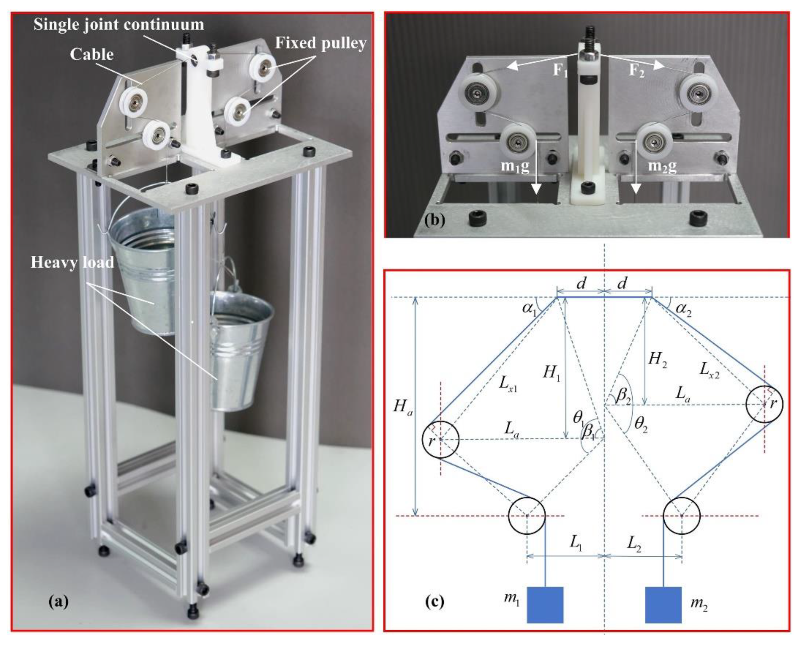
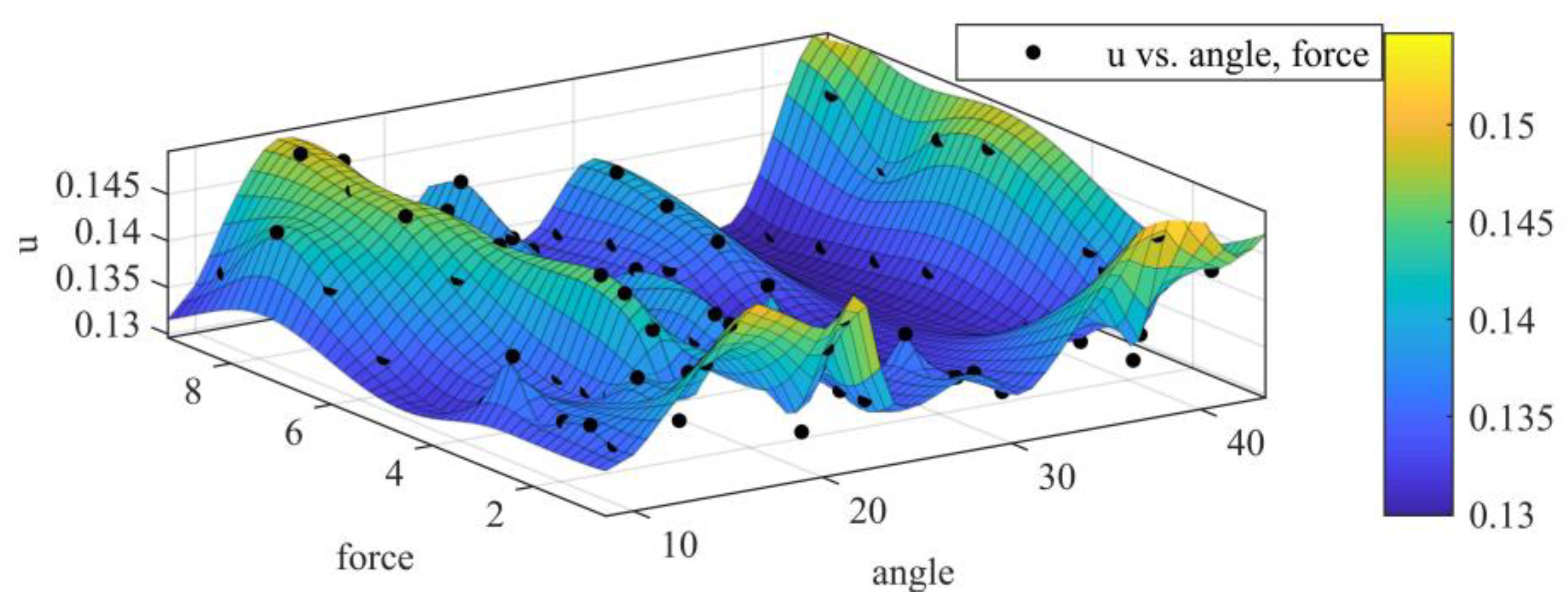
4. Determination of Friction Coefficient

In the hypothesis of a large deformation beam with non-constant curvature, the friction between the cable and NCR is an essential factor affecting the bending of the beam. Therefore, the friction coefficient between the cable and NCR under load must be obtained by the experiment.
The experimental platform to determine the coefficient of friction is illustrated in Figure 7a. The forces on the cable and the NCR are shown in Figure 7b. Figure 7c is the experimental schematic diagram of the friction coefficient measurement experiment. By changing the position of the pulleys on both sides (adjusting the height of the pulleys H i ), the angle α i between the cable and the continuum can be changed. At the same time, the experiment altered the mass of the standard weights m i on both sides until it reached the equilibrium state and then used Equation (21) to solve μ where L x i is the length from the center of pulleys to the top cable; L a , L i is the distance from the upper pulley and the lower pulley to the centerline, respectively; θ i , β i is the angle of the triangles (as shown in Figure 7c). The specific calculation process is as follows:
{ α i = π arctan H i d arcsin L a sin β i L x i arcsin r L x i θ i = π arctan d H i arctan L i H a H i β i = θ i π 2 + arctan L i H a H i L x i = L a 2 + H i 2 + d 2 2 L a H 2 + d 2 cos β i
μ = ( m 1 + m 2 ) sin α 1 + α 2 2 + ( m 1 + m 2 ) 2 sin 2 α 1 + α 2 2 ( m 1 m 2 ) 2 sin α 1 sin α 2 2 ( m 1 m 2 ) sin α 1 2 sin α 2 2
To explore the different factors influencing the friction coefficient and obtain a more accurate friction coefficient, the experiment changed the deflection angles and the mass of the weights. The 100 groups of experimental data were obtained. Surfacing fitting was carried out according to the experimental data. The experimental results are illustrated in Figure 8.

5. Accuracy Verification Experiment of the Static Model

To verify the validity of curvature correction of the proposed static model, the deformation parameters of the NCR were measured and compared with the simulation results.

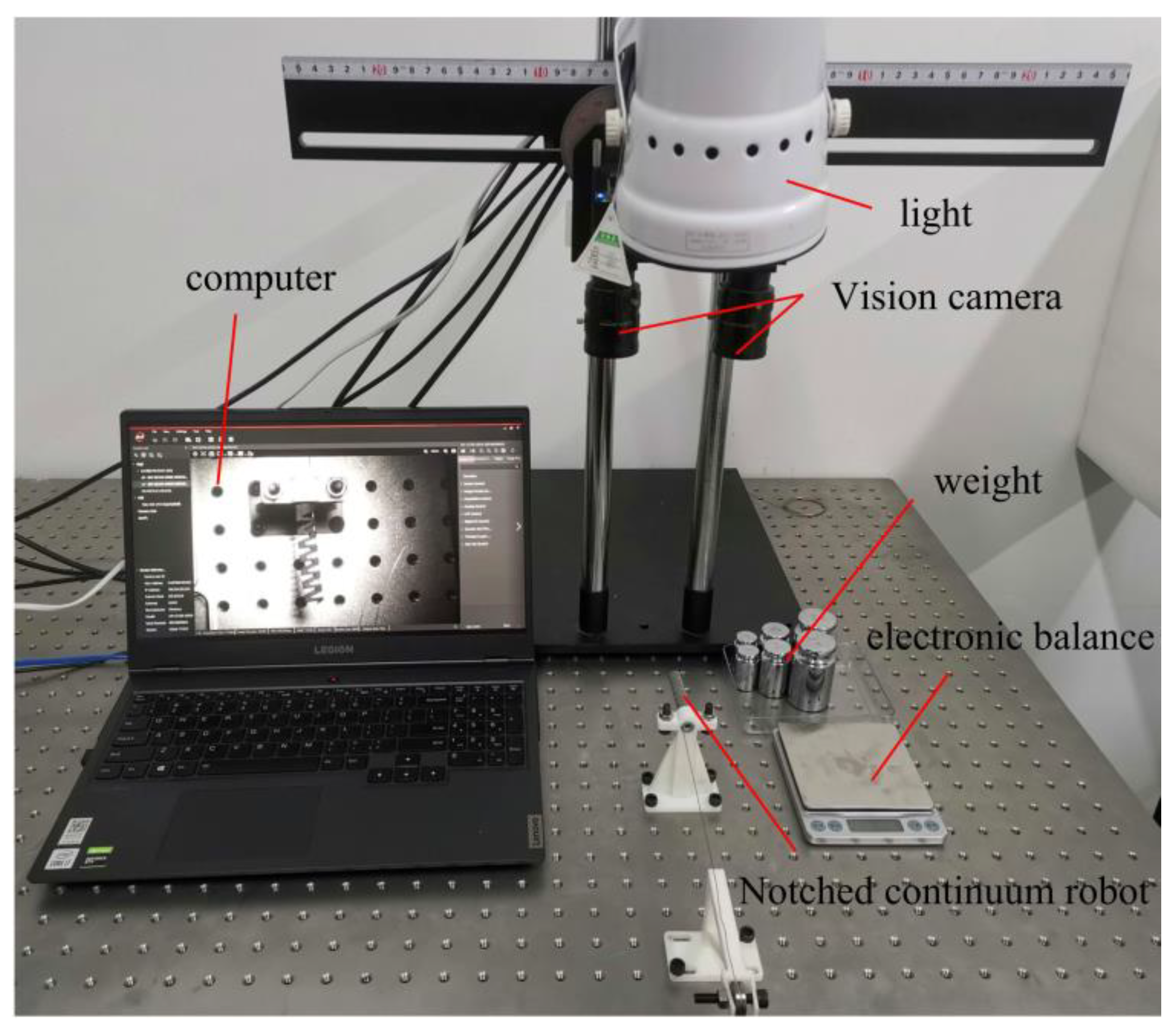
5.1. Experimental Setup

As shown in Figure 9, the experimental platform was used to measure the bending angle of a continuum robot with seven notches. It consisted of two vision cameras (MV-CE100-30GM, Hikvision, Hangzhou, China, distinguishability: 3840 × 2748), a light, and a computer (i7-10750H, NVIDIA GeForce GTX 1650). The cable was connected to the container with standard weights. The weight was controlled by an electronic scale. The vision cameras on both sides of the continuum robot collected the bending angle and tip position in 3D space. The machine vision software (MVS3.3.1, HikRobot, Hangzhou, China) analyzes the images from the image acquisition system MVS.
To measure and verify the static model of NCR proposed in this paper, multiple nylon samples were manufactured by 3D printing. These samples were made of tubes with an outer diameter of 10 mm and an inner diameter of 6 mm (see Table 2), with seven identical equivalent beams.

5.2. Calibration of Elastic Modulus

Two visual cameras were calibrated by the “Stereo Camera Calibrator, MatlabR2020a, MathWorks, Natick, USA” before being used.
Because the notched continuum robot used in the experiment was made by 3D printing, its material density and elastic modulus were significantly affected by the quality of the printer and environment. Therefore, several single-end notch continuums with the same parameters were manufactured in this experiment, and their bending under different forces conditions was measured. Finally, the elastic modulus of the notched continuum robot was calibrated in the opposite direction. Figure 10 shows the deformation of a single-notched continuum robot under different forces. The final modulus of elasticity of the continuum was designated as 1000.406 MPa. The red dots are the deformation characteristic points of NCR (see Figure 10 and Figure 11). The deformation parameters of the NCR are obtained by calibration of red dots.

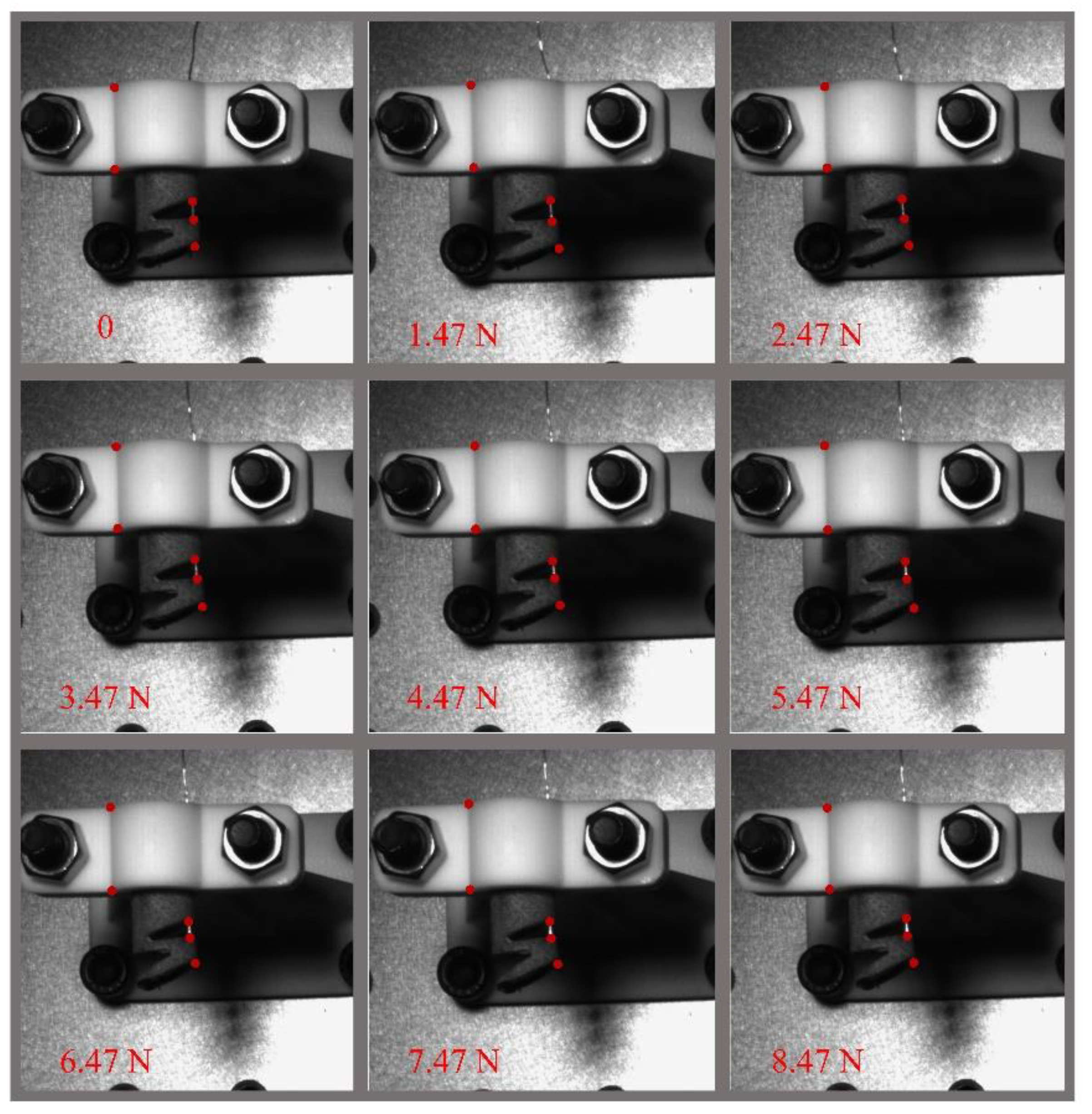
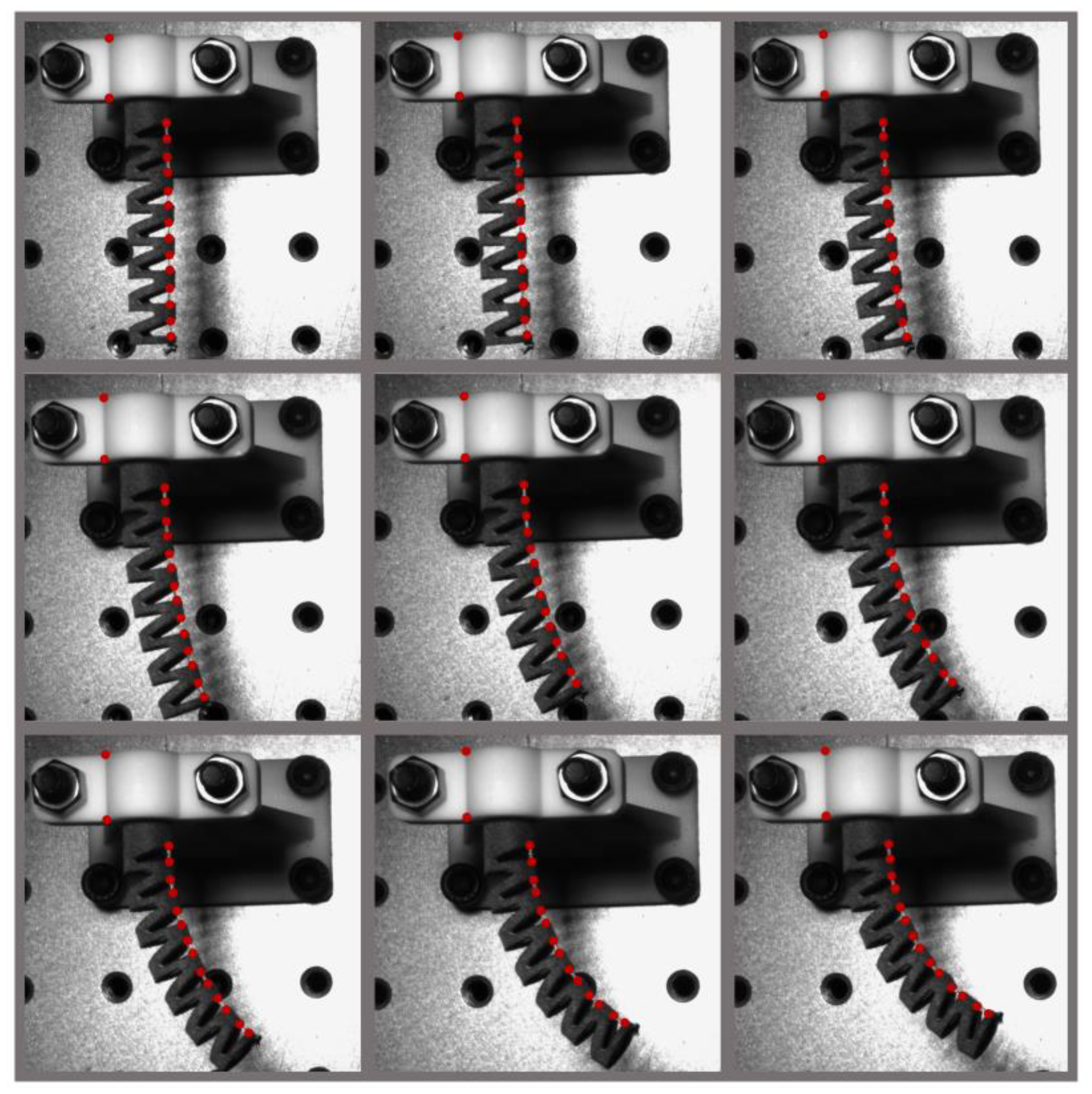
5.3. Error and Result Analysis

Figure 11 shows the bending of NCR in the 2D plane from the straight configuration to θ = 58° (The drive forces are the same as in the previous section). The bending angles are measured by vision cameras and the VM algorithm platform. In Figure 12, the simulation results of the research overlayed with experimental data. Figure 12 compares the experiment results and three sets of simulation data. The simulation data correspond to the large deformation theory, frictionless theory, and the static model proposed, respectively. In the θ-F curve, the simulation results considering large deformation and friction effect are highly consistent with the experimental data. The root-mean-square error (RMSE) of the static model proposed in this paper, the friction-less model, and the small deformation model is 2.4409°, 5.1016° and 10.0972°, respectively. It proves the model’s feasibility in accurately correcting NCR’s curvature. The error may come from the insufficient stiffness of the continuum backbone with the increased load.
To further validate the advantage of the large deformation theory compared with small deformation, the deformation parameters of every single notch in NCR were measured under different forces. Error comparisons were made between the simulation results in both cases, as shown in Figure 13. The bending experiment was repeated many times. The RMSEs of the bending angle considering our proposed model and the model based on small deformation theory are 0.43° and 1.47°, respectively. The smaller RMSE reflects higher accuracy of static models considering large deformation.
External loading tests on the continuum robot end are illustrated in Figure 14. When the external load is small, the static model proposed in this paper, the small deformation model, and the friction-less model are all close to the experimental results. However, with the load increase, the model considering large deformation and friction effect is closer to the experimental results than the other model. It demonstrates that the static model considering large deformation and friction effect has higher precision.

6. Discussion and Conclusions

A static model of a triangular-notched continuum robot considering the large deformation and friction effect is proposed in this paper. Due to the friction effect between the cables and the continuum robots, the Piecewise Constant Curvature assumption is often not applicable. Therefore, the model presents a method of curvature correction of the NCR. The friction effect and the coupling effect of forces between multiple notches are considered in it. The recurrence relationship of the force on the cable is obtained by mechanical analysis. Through an iteration method, the exact single-notch deformation parameters are solved in the case of multi-notch deformation coupling. Finally, the verification experiment of a triangular-notched continuum robot with seven notches is implemented. The experimental results indicate that the error of the static model based on large deformation (2.4409°) is significantly smaller than the friction-less model and the model based on small deformation (5.1016°, 10.0972°). Moreover, compared with the small deformation assumption, the advantage and validity of the large deformation assumption are verified. The RMSE of the bending angle in every notch considering the large deformation assumption is 0.43°, significantly smaller than the model based on the small deformation assumption (1.47°). The proposed static model can not only correct the piecewise constant curvature of NCR under the friction effect but also guide the structural design of similar notched continuum robotic wrists.
In our future work, the model will consider the influence of torsion on NCR, the change of elastic modulus of experimental materials, and optimize the design according to the stiffness and bending angle requirements.

Author Contributions

Conceptualization, J.L. and G.Z.; methodology, J.L. and S.S.; software, G.Z., S.X. and H.C.; formal analysis, J.L. and S.S.; resources G.Z., F.D. and P.Q.; data curation, J.L. and S.S.; writing—original draft preparation, J.L. and S.S.; writing—review and editing, F.D.; visualization, J.L., S.S. and G.Z.; supervision, G.Z. and F.D.; project administration, F.D.; funding acquisition, F.D. All authors have read and agreed to the published version of the manuscript.

Funding

This work was supported by the China Postdoctoral Science Foundation funded project (Grant No. 2019M662346), the Shandong Provincial Postdoctoral Innovative Talents Funded Scheme (Grant No. 238226), the Focus on Research and Development Plan in Shandong Province (Grant No. 2022CXGC010503), the Intelligent Robots and Systems High-Precision Innovation Center Open Fund (Grant No. 2019IRS06), the Fundamental Research Funds for the Central Universities and the Young Scholars Program of Shandong University.

Data Availability Statement

Not applicable.

Conflicts of Interest

The authors declare no conflict of interest.

References

  1. Trivedi, D.; Rahn, C.D.; Kier, W.M.; Walker, I.D. Soft robotics: Biological inspiration, state of the art, and future research. Appl. Bionics Biomech. 2008, 5, 99–117. [Google Scholar] [CrossRef]
  2. Webster, R.J.; Okamura, A.M.; Cowan, N.J. Toward active cannulas: Miniature snake-like surgical robots. In Proceedings of the 2006 IEEE/RSJ International Conference on Intelligent Robots and Systems, Beijing, China, 9–15 October 2006; pp. 2857–2863. [Google Scholar]
  3. Hannan, M.W.; Walker, I.D. Analysis and experiments with an elephant’s trunk robot. Adv. Robot. 2001, 15, 847–858. [Google Scholar] [CrossRef] [PubMed]
  4. Tsukagoshi, H.; Kitagawa, A.; Segawa, M. Active hose: An artificial elephant’s nose with maneuverability for rescue operation. In Proceedings of the Proceedings 2001 ICRA. IEEE International Conference on Robotics and Automation (Cat. No. 01CH37164), Seoul, Korea, 21–26 May 2001; pp. 2454–2459. [Google Scholar]
  5. Napadow, V.J.; Kamm, R.D.; Gilbert, R.J. A biomechanical model of sagittal tongue bending. J. Biomech. Eng. 2002, 124, 547–556. [Google Scholar] [CrossRef]
  6. Rone, W.S.; Ben-Tzvi, P. Continuum robotic tail loading analysis for mobile robot stabilization and maneuvering. In Proceedings of the International Design Engineering Technical Conferences and Computers and Information in Engineering Conference, Buffalo, NY, USA, 17–20 August 2014; p. V05AT08A009. [Google Scholar]
  7. Guglielmino, E.; Tsagarakis, N.; Caldwell, D.G. An octopus anatomy-inspired robotic arm. In Proceedings of the 2010 IEEE/RSJ International Conference on Intelligent Robots and Systems, Taipei, Taiwan, 18–22 October 2010; pp. 3091–3096. [Google Scholar]
  8. Webster, R.J., III; Jones, B.A. Design and kinematic modeling of constant curvature continuum robots: A review. Int. J. Robot. Res. 2010, 29, 1661–1683. [Google Scholar] [CrossRef]
  9. Nakadate, R.; Iwasa, T.; Onogi, S.; Arata, J.; Oguri, S.; Okamoto, Y.; Akahoshi, T.; Eto, M.; Hashizume, M. Surgical Robot for Intraluminal Access: An Ex Vivo Feasibility Study. Cyborg Bionic Syst. 2020, 2020, 8378025. [Google Scholar] [CrossRef]
  10. Ohuchida, K. Robotic Surgery in Gastrointestinal Surgery. Cyborg Bionic Syst. 2020, 2020, 9724807. [Google Scholar] [CrossRef]
  11. So, J.; Kim, U.; Kim, Y.B.; Seok, D.-Y.; Yang, S.Y.; Kim, K.; Park, J.H.; Hwang, S.T.; Gong, Y.J.; Choi, H.R. Shape Estimation of Soft Manipulator Using Stretchable Sensor. Cyborg Bionic Syst. 2021, 2021, 9843894. [Google Scholar] [CrossRef]
  12. Chiluisa, A.J.; Van Rossum, F.J.; Gafford, J.B.; Labadie, R.F.; Webster, R.J.; Fichera, L. Computational optimization of notch spacing for a transnasal ear endoscopy continuum robot. In Proceedings of the 2020 International Symposium on Medical Robotics (ISMR), Atlanta, GA, USA, 18–20 November 2020; pp. 188–194. [Google Scholar]
  13. Eastwood, K.W.; Swarup, A.; Francis, P.; Alvara, A.N.; Chen, H.; Looi, T.; Naguib, H.E.; Drake, J.M. A steerable neuroendoscopic instrument using compliant contact-aided joints and monolithic articulation. J. Med. Devices 2020, 14, 025002. [Google Scholar] [CrossRef]
  14. Ding, J.; Goldman, R.E.; Xu, K.; Allen, P.K.; Fowler, D.L.; Simaan, N. Design and coordination kinematics of an insertable robotic effectors platform for single-port access surgery. IEEE/ASME Trans. Mechatron. 2012, 18, 1612–1624. [Google Scholar] [CrossRef]
  15. Zhang, G.; Du, F.; Xue, S.; Cheng, H.; Zhang, X.; Song, R.; Li, Y. Design and Modeling of a Bio-Inspired Compound Continuum Robot for Minimally Invasive Surgery. Machines 2022, 10, 468. [Google Scholar] [CrossRef]
  16. York, P.A.; Swaney, P.J.; Gilbert, H.B.; Webster, R.J. A wrist for needle-sized surgical robots. In Proceedings of the 2015 IEEE International Conference on Robotics and Automation (ICRA), Seattle, WA, USA, 26–30 May 2015; pp. 1776–1781. [Google Scholar]
  17. Kutzer, M.D.; Segreti, S.M.; Brown, C.Y.; Armand, M.; Taylor, R.H.; Mears, S.C. Design of a new cable-driven manipulator with a large open lumen: Preliminary applications in the minimally-invasive removal of osteolysis. In Proceedings of the 2011 IEEE International Conference on Robotics and Automation, Shanghai, China, 9–13 May 2011; pp. 2913–2920. [Google Scholar]
  18. Eastwood, K.W.; Azimian, H.; Carrillo, B.; Looi, T.; Naguib, H.E.; Drake, J.M. Kinetostatic design of asymmetric notch joints for surgical robots. In Proceedings of the 2016 IEEE/RSJ International Conference on Intelligent Robots and Systems (IROS), Daejeon, Korea, 9–14 October 2016; pp. 2381–2387. [Google Scholar]
  19. Francis, P.; Eastwood, K.W.; Bodani, V.; Price, K.; Upadhyaya, K.; Podolsky, D.; Azimian, H.; Looi, T.; Drake, J. Miniaturized instruments for the da Vinci research kit: Design and implementation of custom continuum tools. IEEE Robot. Autom. Mag. 2017, 24, 24–33. [Google Scholar] [CrossRef]
  20. Li, S.; Hao, G. Current trends and prospects in compliant continuum robots: A survey. Actuators 2021, 10, 145. [Google Scholar] [CrossRef]
  21. Yip, M.C.; Camarillo, D.B. Model-less hybrid position/force control: A minimalist approach for continuum manipulators in unknown, constrained environments. IEEE Robot. Autom. Lett. 2016, 1, 844–851. [Google Scholar] [CrossRef]
  22. Xu, K.; Simaan, N. An investigation of the intrinsic force sensing capabilities of continuum robots. IEEE Trans. Robot. 2008, 24, 576–587. [Google Scholar] [CrossRef]
  23. Zheng, T.; Branson, D.T.; Guglielmino, E.; Kang, R.; Medrano Cerda, G.A.; Cianchetti, M.; Follador, M.; Godage, I.S.; Caldwell, D.G. Model validation of an octopus inspired continuum robotic arm for use in underwater environments. J. Mech. Robot. 2013, 5, 021004. [Google Scholar] [CrossRef]
  24. Bergeles, C.; Gosline, A.H.; Vasilyev, N.V.; Codd, P.J.; Pedro, J.; Dupont, P.E. Concentric tube robot design and optimization based on task and anatomical constraints. IEEE Trans. Robot. 2015, 31, 67–84. [Google Scholar] [CrossRef]
  25. Legrand, J.; Ourak, M.; Vandebroek, T.; Vander Poorten, E. A large displacement model for superelastic material side-notched tube instruments. Int. J. Mech. Sci. 2021, 197, 106329. [Google Scholar] [CrossRef]
  26. Cheng, H.; Liu, H.; Wang, X.; Liang, B. Approximate piecewise constant curvature equivalent model and their application to continuum robot configuration estimation. In Proceedings of the 2020 IEEE International Conference on Systems, Man, and Cybernetics (SMC), Toronto, ON, Canada, 11–14 October 2020; pp. 1929–1936. [Google Scholar]
  27. Du, Z.; Yang, W.; Dong, W. Kinematics modeling of a notched continuum manipulator. J. Mech. Robot. 2015, 7, 041017. [Google Scholar] [CrossRef]
  28. Gao, A.; Murphy, R.J.; Liu, H.; Iordachita, I.I.; Armand, M. Mechanical model of dexterous continuum manipulators with compliant joints and tendon/external force interactions. IEEE/ASME Trans. Mechatron. 2016, 22, 465–475. [Google Scholar] [CrossRef]
  29. Jones, B.A.; Gray, R.L.; Turlapati, K. Three dimensional statics for continuum robotics. In Proceedings of the 2009 IEEE/RSJ International Conference on Intelligent Robots and Systems, St. Louis, MO, USA, 10–15 October 2009; pp. 2659–2664. [Google Scholar]
  30. Rucker, D.C.; Webster III, R.J. Statics and dynamics of continuum robots with general tendon routing and external loading. IEEE Trans. Robot. 2011, 27, 1033–1044. [Google Scholar] [CrossRef]
  31. Eastwood, K.W.; Francis, P.; Azimian, H.; Swarup, A.; Looi, T.; Drake, J.M.; Naguib, H.E. Design of a contact-aided compliant notched-tube joint for surgical manipulation in confined workspaces. J. Mech. Robot. 2018, 10, 015001. [Google Scholar] [CrossRef]
  32. Wei, D.; Wenlong, Y.; Dawei, H.; Zhijiang, D. Modeling of flexible arm with triangular notches for applications in single port access abdominal surgery. In Proceedings of the 2012 IEEE International Conference on Robotics and Biomimetics (ROBIO), Guangzhou, China, 11–14 December 2012; pp. 588–593. [Google Scholar]
  33. Fichera, L.; Dillon, N.P.; Zhang, D.; Godage, I.S.; Siebold, M.A.; Hartley, B.I.; Noble, J.H.; Russell, P.T.; Labadie, R.F.; Webster, R.J. Through the eustachian tube and beyond: A new miniature robotic endoscope to see into the middle ear. IEEE Robot. Autom. Lett. 2017, 2, 1488–1494. [Google Scholar] [CrossRef] [PubMed]
  34. Zhang, T.; Ping, Z.; Zuo, S. Miniature continuum manipulator with three degrees-of-freedom force sensing for retinal microsurgery. J. Mech. Robot. 2021, 13, 041002. [Google Scholar] [CrossRef]
  35. Simaan, N.; Xu, K.; Wei, W.; Kapoor, A.; Kazanzides, P.; Taylor, R.; Flint, P. Design and integration of a telerobotic system for minimally invasive surgery of the throat. Int. J. Robot. Res. 2009, 28, 1134–1153. [Google Scholar] [CrossRef] [PubMed]
  36. Huang, J.; Wang, H.; Tian, S.; Zhang, F. Modeling of notched variable stiffness continuum flexible snake-like robot. In Proceedings of the 2018 International Automatic Control Conference (CACS), Taoyuan, Taiwan, 4–7 November 2018; pp. 1–6. [Google Scholar]
  37. Yang, Z.; Yang, W.; Du, Z. Kinematics modelling of tendon-driven continuum manipulator with crossed notches. In Proceedings of the IOP Conference Series: Materials Science and Engineering, Hong Kong, 12–14 December 2017; p. 012005. [Google Scholar]
  38. Wang, H.; Wang, X.; Yang, W.; Du, Z. Design and kinematic modeling of a notch continuum manipulator for laryngeal surgery. Int. J. Control Autom. Syst. 2020, 18, 2966–2973. [Google Scholar] [CrossRef]
  39. Lee, K. Large deflections of cantilever beams of non-linear elastic material under a combined loading. Int. J. Non-Linear Mech. 2002, 37, 439–443. [Google Scholar] [CrossRef]
  40. Walker, A.; Hall, D. An analysis of the large deflections of beams using the Rayleigh-Ritz finite element method. Aeronaut. Q. 1968, 19, 357–367. [Google Scholar] [CrossRef]
  41. Tada, Y.; Lee, G.C. Finite element solution to an elastica problem of beams. Int. J. Numer. Methods Eng. 1970, 2, 229–241. [Google Scholar] [CrossRef]
  42. Beléndez, T.; Neipp, C.; Beléndez, A. Large and small deflections of a cantilever beam. Eur. J. Phys. 2002, 23, 371. [Google Scholar] [CrossRef]
  43. Mutyalarao, M.; Bharathi, D.; Rao, B.N. Large deflections of a cantilever beam under an inclined end load. Appl. Math. Comput. 2010, 217, 3607–3613. [Google Scholar] [CrossRef]
  44. Bisshopp, K.; Drucker, D. Large deflection of cantilever beams. Q. Appl. Math. 1945, 3, 272–275. [Google Scholar] [CrossRef]
  45. Howell, L.L.; Midha, A. Parametric deflection approximations for end-loaded, large-deflection beams in compliant mechanisms. J. Mech. Des. 1995, 117, 156–165. [Google Scholar] [CrossRef]
  46. Kimball, C.; Tsai, L.-W. Modeling of flexural beams subjected to arbitrary end loads. J. Mech. Des. 2002, 124, 223–235. [Google Scholar] [CrossRef]
Figure 1. The illustration of the structure: (a) 3D model of the NCR, (b) structural parameters of a single notch, (c) different parts of joint.
Machines 10 00778 g001
Figure 2. Force on end notch of the NCR.
Machines 10 00778 g002
Figure 3. A model of a single notch.
Machines 10 00778 g003
Figure 4. Schematic of NCR being bent under the cable force.
Machines 10 00778 g004
Figure 5. Analysis diagram of the equivalent beam loaded with an external concentrated load (F) at the end of the beam.
Machines 10 00778 g005
Figure 6. Iterative computation process to solve for bending angle considering the contact friction effect and the coupling effect of forces between multiple notches.
Machines 10 00778 g006
Figure 7. The experiment of determination of friction coefficient: (a) Experimental platform; (b) Enlarged view of experimental platform; (c) Experimental schematic diagram.
Machines 10 00778 g007
Figure 8. Fitted three-dimensional network of friction coefficient.
Machines 10 00778 g008
Figure 9. Experimental setups for the mechanics model verification.
Machines 10 00778 g009
Figure 10. Elastic modulus calibration in a single-notched continuum robot.
Machines 10 00778 g010
Figure 11. Bending of NCR with seven notches under different forces.
Machines 10 00778 g011
Figure 12. Bending angle-cable force relationship of NCR.
Machines 10 00778 g012
Figure 13. Bending angle error of every single notch under different forces.
Machines 10 00778 g013
Figure 14. Deformation diagram of NCR under external loading test.
Machines 10 00778 g014
Table 1. The descriptions of each parameter in Figure 4.
ParameterDescription
FiTension force on cable i
Fi−1Tension force on cable i − 1
NiSupporting force exerted by the continuum robot
fiFriction force exerted by the continuum robot
NiThe supporting force applied by the cable to the continuum robot (not shown in the figure)
fiFriction force applied by the cable to the continuum robot (not shown in the figure)
γiThe angle between cable i and the cable i − 1
Table 2. Geometric parameters and material properties of the proposed continuum robot.
ParameterUnit/mm
D10
d6
h1.5
H3.5
ω6.9
materialNylon
Publisher’s Note: MDPI stays neutral with regard to jurisdictional claims in published maps and institutional affiliations.

