Article

6-DOF Bilateral Teleoperation Hybrid Control System for Power Distribution Live-Line Operation Robot

1
CAS Key Laboratory of Mechanical Behavior and Design of Materials, Department of Precision Machinery and Precision Instrumentation, University of Science and Technology of China, Hefei 230026, China
2
State Grid Anhui Electric Power Company, Hefei 230061, China
3
State Grid Anhui Electric Power Company Electric Power Research Institute, Hefei 230601, China
4
State Grid Intelligent Technology Co., Ltd., Jinan 250104, China
*
Author to whom correspondence should be addressed.
Machines 2023, 11(1), 2; https://doi.org/10.3390/machines11010002
Submission received: 21 November 2022 / Revised: 9 December 2022 / Accepted: 13 December 2022 / Published: 20 December 2022
(This article belongs to the Special Issue Advances in Electric Power Systems and Microgrids)

Abstract

:
In the master-slave heterogeneous teleoperation, the workspace of the slave manipulator is usually much larger than that of the master manipulator. This paper proposes a 6-DOF bilateral hybrid teleoperation control strategy to map the workspace of the manipulators without changing the operation accuracy. The hybrid control includes the admittance and force control based on the feedback of the force sensor at the end of the manipulator. The two control strategies switched autonomously through the positioning of the Sigma.7 handle in the workspace. Compared with the classic bilateral teleoperation control, it overcomes the limitation of pre-matching the workspace of the master and slave. When the tool contacts a rigid environment, the robot can make adaptive compensation through the admittance controller even if the operator has not responded. We conduct extensive experiments to evaluate the changes in displacement and velocity before and after the switching process and under different admittance controller parameters. Finally, teleoperation is applied to live-line operation in distribution networks. The experiment proved that the control strategy is more consistent with human operation habits and can improve assembly success rate and efficiency.

1. Introduction

The size of the global grid is growing, and existing transmission and distribution lines are aging. Accordingly, the maintenance and overhaul of power grid lines are becoming increasingly prominent. Live-line work is a method widely recognized by the power system to overhaul high-voltage electrical equipment without power failure, thus, ensuring uninterrupted power supply for users and improving social economic benefits. Workers are required to operate in an aerial environment under high-temperature and high-voltage conditions, making their jobs difficult and dangerous [1]. Therefore, it is necessary to develop a power distribution live-line operation robot (PDLOR) to replace workers in harsh environments to ensure personnel safety and improve work efficiency. In the past, many countries have carried out a number of studies on the key technologies of PDLORs [2,3].
Among them, teleoperation technology as a stable and reliable remote control method can adapt to simultaneously completing a variety of live-line work and can be flexibly adjusted in unstructured scenarios [4]. During teleoperation, an operator conducts remote observation and control on the ground [5,6,7]. Short delay, immense field-angle visual feedback, and high tracking performance of a master-slave manipulator can significantly increase the transparency of a teleoperation system. The latest teleoperation technologies have combined visual feedback, force feedback, and tactile feedback to increase the transparency of teleoperation systems [8,9,10,11].
When the master hand and the remote manipulator have the same topology, joint angles are usually used for mapping control [12]. However, when the size of the master hand is much smaller than that of the slave manipulator, the displacement and speed on the end of the master are amplified for the slave, which makes the fine operation quite difficult. There are many mapping methods for heterogeneous teleoperation, such as joint–joint mapping, point–point mapping in the workspace, rate mapping, and hybrid mapping [13,14,15,16,17]. The main problems are the difference between the master and slave motion tracks and the difference between the master and slave workspaces [18]. Li et al. [19] proposed a master–slave heterogeneous mapping method based on link-attitude constraint. Gong et al. [20] captured the motion data of a human arm with a wearable motion-capturing system and matched it to a remote manipulator. Using an appropriate motion-matching teleoperation strategy can result in more consistency with human operation habits and can reduce the processes of learning and adaptation.
Live-line work tasks [21,22] can be divided into two categories according to the type of contact used when a robot works. One type is flexible contact between a tool and an object, such as the contact between a wire connection tool and a wire during power line connection work, which can be accomplished via visual recognition, positioning, and robot planning [23]. The other type is rigid contact, such as the process of assembling a peg hole between the copper connection terminal of a wire and a lightning arrester during arrester installation, a process that can only be completed under vision /force fusion [22].
During the whole operation process, a remote manipulator needs to complete wire grasping and installation, as well as arrester gripping and other operations. This requires a teleoperation system to control a remote manipulator’s movement in a range that is far larger than that of the working space of the master robot; at the same time, it needs to conduct fine-scale shaft-hole assembly operations in contact with the rigid environment. Bilateral teleoperation control [24,25] is a solution for contact tasks. However, most of the prior research is focused on bilateral control under variable delay [26], which can be ignored for the close-distance (about 10 m) teleoperation of a PDLOR. We focus on bilateral control under the condition that the workspace of the master robot is much smaller than that of the remote manipulator in a master–slave heterogeneous teleoperation system. At the same time, when a tool contacts a rigid environment, the slave manipulator can show a certain degree of flexibility.
To map the motion of the master device to the remote manipulator and provide the operator with a natural operating experience, a virtual reality bilateral hybrid teleoperation control system is constructed in this study. The proposed control system consists of three parts:
(1)
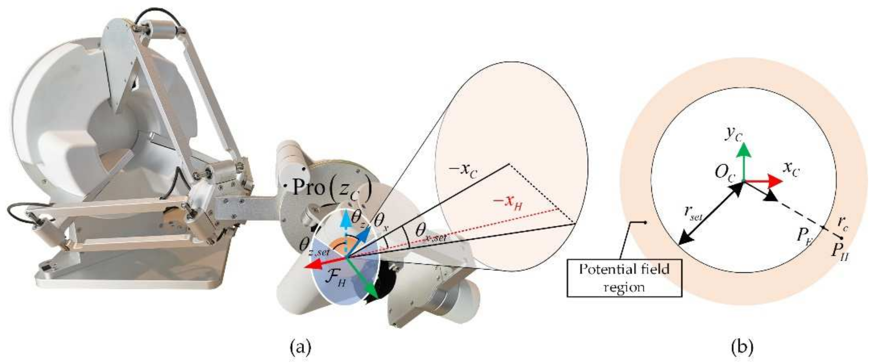
Mapping between the master device and the remote device. In view of the inconsistent configurations of the master device and the remote manipulator, as well as the large difference in the size of the workspaces, a hybrid control strategy is designed to switch automatically according to the current position and rotation on the end of the master device.
(2)
Haptic rendering of the feedback force from the end-force sensor when a tool interacts with the environment, and haptic rendering of the virtual force generated by superimposing the virtual simulation space. This feedback enables the operator to perceive interactions between the remote robot and the environment while being guided by the virtual force field.
(3)
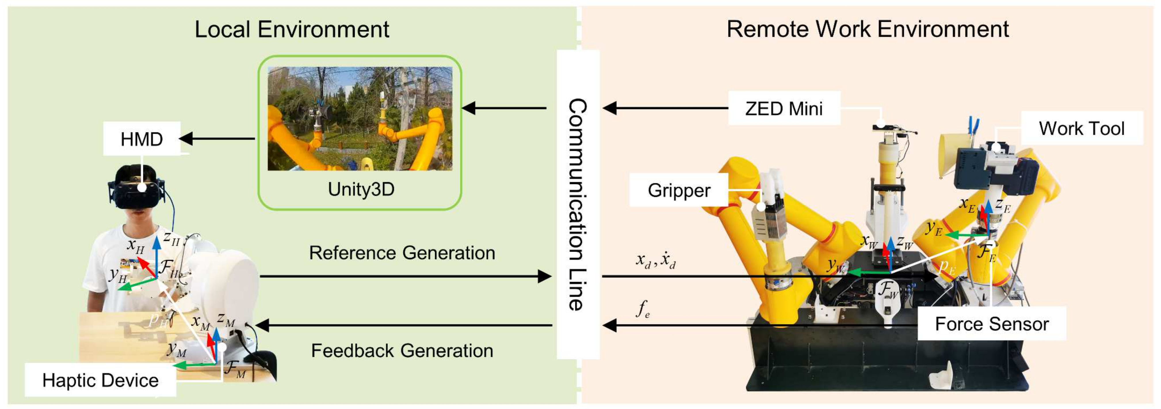
Real-time rendering of binocular vision from the robot visual perception system of the head-mounted display (HMD). During teleoperation training, this can be switched to the visualization of a virtual simulation environment for teleoperation skill training.
(4)
Through the integration of the above parts, a human-centered teleoperation system that conforms to human operating habits is constructed.

2. Estimation of Contact Forces

A 6-D force sensor is installed between the end of the manipulator and the tool. The value of the force sensor is affected by the weight of the tool and the posture of the manipulator. Thus, the sensor value was not equal to the environmental contact force. We need to balance the force and torque produced by the end tool under gravity [27].
Assuming that the initial value of the 6-D force sensor is τ ^ 0 6 under the condition of no force, F 0 , M 0 3 are the force and torque components, respectively. Similarly, the actual contact force between the tool and the environment is τ ^ e x t 6 . The force and torque are F e x t , M e x t 3 , respectively. When the sensor is subjected to environmental contact force and tool gravity, the reading is τ ^ S 6 , and F S = F S , x F S , y F S , z Τ   M S = T S , x T S , y T S , z Τ are the force and torque components of τ ^ S , respectively. The relative coordinate of the center of gravity on the tool in the sensor coordinate system F S is p t , S = p t , x , p t , y , p t , z Τ . The gravity of the tool in world coordinates F W is G t , W = 0 , 0 , g t , z Τ . The relationship between the value of the force sensor, the attitude of the manipulator, and the gravity of the tool when there is τ ^ e x t under F S can then be obtained as shown in (1) and (2):
τ ^ e x t = F e x t M e x t = F S F 0 ( R S W ) Τ G t , W M S M 0 K 1 ( R S W ) T G t , W
K 1 = 0 p t , z p t , y p t , z 0 p t , x p t , y p t , x 0
where R S W = R B W R E B R S E , K 1 is the antisymmetric matrix with respect to p t , S , transforming the force into the corresponding torque. R B W S O ( 3 ) is the rotation matrix of the base of the manipulator relative to F W . R E B S O ( 3 ) is the rotation matrix of the end of the robot relative to the base, which changes with the posture of the manipulator. R S E S O ( 3 ) is the rotation matrix of the sensor relative to the robot end of the manipulator. τ ^ 0 ,   p t , S , and G t , W can be solved with the following:
k t , S = M 0 K 1 F 0
When τ ^ e x t is equal to 0, combining (1), (2), and (3) yields the following:
M S = K 1 F S + k t , S
The variables and constants are separated:
M S = K 2 I p t , S k t , S
K 2 = 0 F S , z F S , y F S , z 0 F S , x F S , y F S , x 0
where I is a third-order unit matrix with unknowns concentrated in the rightmost matrix of (5). p t , S and k t , S are obtained by measuring n   ( n 3 ) groups M S , K 2 under different attitudes and solving the overdetermined linear equation system using the least squares method. Similarly, (7) can be obtained by converting (1), and G t , W , F 0 can be obtained by solving multiple groups of F S , R S W :
F S = ( R S W ) Τ I G t , W F 0
Finally, the solved parameters are input into (3) to calculate M 0 . At this point, the identification of the initial values of the force sensor and load parameters of the robot end tool is complete. Through (1), the current external force τ ^ e x t under different manipulator postures can be obtained.

3. Teleoperation System

3.1. Teleoperation Control Route

In this section, we introduce in detail the force feedback teleoperation framework combined with virtual reality. The teleoperation system built in this study was divided into two parts: the master control haptic device and the remote PDLOR. The master operating end was located on the ground and included a 7-DOF force feedback handle similar to Sigma.7, a wearable HTC VIVE display, and an industrial computer. The remote end consisted of a PDLOR with two UR10 manipulators installed at 45° inclinations from the main body, as shown in Figure 1. The end of the manipulator was equipped with an ATI 6-D force sensor that was connected with the work tool through a flange and a quick-change interface. The visual perception system was integrated on a post behind the robot and included a monocular camera and a zed Mini binocular stereo camera, which could observe video footage from different perspectives with the movement of a 2-D PTZ. Each end was equipped with an industrial computer that interacted with the sensors and actuators, which were connected to each other. The industrial computers used TCP/IP network protocol to communicate through a wireless bridge [28].

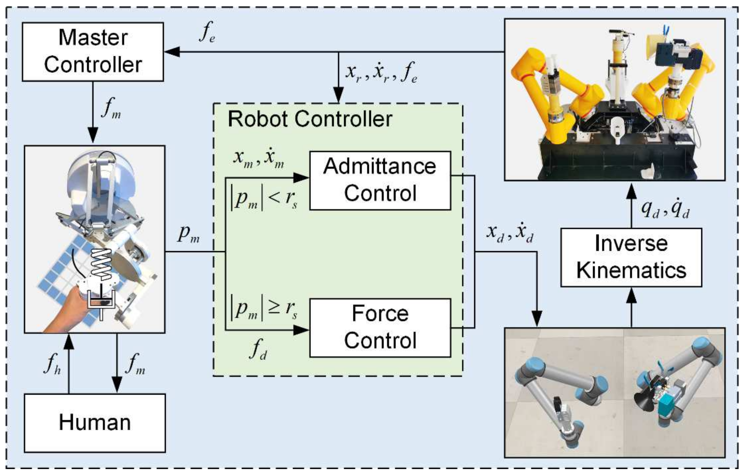
3.2. Teleoperation Hybrid Control

3.2.1. Admittance Teleoperation Control Mode

To be able to perform operations involving contact with the environment during teleoperation, we added an admittance control in the task space (world cartesian coordinate system) to the position-based bilateral control. This addition enabled the manipulator to exhibit elastic properties, such as a mass–spring–damper system with a small range of adaptive capabilities [29,30].
We defined F M as the coordinate system of the master-end haptic device and F H as the coordinate system of the human hand in contact with the master device, which was consistent with the pose of the master end. p S B 3 and v S B 3 are used to denote the position and velocity, respectively, of the robot arm end-sensor’s center O S in F B . The attitude and angular velocity of F S relative to F B are R S B S O ( 3 ) and ω S B 3 , respectively. The attitude of F B relative to F W is R B W S O ( 3 ) . Therefore, the closed-loop kinetic equation in F S can be obtained as follows:
M A v ˙ S S ω ˙ S S + D A e v e ω + K A e p e R = τ ^ e x t
where virtual inertia M A 6 × 6 , virtual damping D A 6 × 6 , and virtual stiffness K A 6 × 6 are the adjustment parameters of the controller. τ ^ e x t 6 is the interaction force between the tool and the environment in F S . e p , e R , e v , e ω represent the tracking error values of the state parameters for the current feedback on the manipulator’s end relative to the set reference value. Their specific expressions in F S are as follows:
e p = ( R S B ) Τ ( p S B p S , r e f B )
e R = R o d r i g u e s ( ( R S B ) Τ R S , r e f B )
e v = ( R S B ) T ( v S B v S , r e f B )
e ω = ( R S B ) Τ ( ω S B ω S , r e f B )
where p S , r e f B 3 and v S , r e f B 3 are the expected position and velocity, respectively, in F B . The attitude R S , r e f B S O ( 3 ) and angular velocity ω S , r e f B 3 are also in F B . R o d r i g u e s ( ) s o ( 3 ) is used to convert the rotation matrix to a rotation vector.

3.2.2. Force-Based Speed Control Mode

The workspace of the master device was much smaller than that of the slave, and the two configurations were different. One method of matching the two workspaces is to enlarge the workspace of the master device and then match it with the remote robot. Another method is to perform teleoperation under the ratio of the workspace of the robotic arm to that of the master device, known as the master–slave mapping ratio. This ratio is equivalent to amplifying the displacement mapping and velocity mapping coefficients of teleoperation master–slave matching. Hence, it makes fine-scale local operation relatively difficult. To move or rotate in a large range without affecting the fine-scale local operation, we added a force-based speed control strategy, as shown in Figure 2. The specific description is as follows.
The input of the control strategy is the virtual potential field force τ ^ d 6 generated by the 7-DOF haptic device, and the environmental contact force τ ^ e x t is as calculated in Section 2. The outputs are the moving speed x ˙ d 3 of the end of the manipulator and the speed s d s o ( 3 ) of the rotation vector, which are represented in F W . The relationship between the parameters is shown in (13) and (14):
x ˙ d s d = R S W 0 3 × 3 0 3 × 3 R S W k m τ ^ d τ ^ e x t
R d = e R R E W = R o d r i g u e s 1 ( s d d t ) R E W
where R S W S O ( 3 ) is the rotation matrix of the force sensor in F W , and k m 6 × 6 is the mapping scale factor for displacement and rotation. e R is the accumulated deviation of the rotation matrix in the speed control after integrating s d over time and completing the exponential mapping of the rotation matrix using the Euler–Rodrigues equation: R o d r i g u e s 1 ( ) : s o ( 3 ) S O ( 3 ) . Since the rotation is based on the fixed coordinate system F W , e R is multiplied to the left to obtain R d .

3.3. Force Feedback from Haptic Devices

The haptic device was a force feedback handle similar to Sigma.7, as shown in Figure 3. Joints 1 to 3 were parallel-type mechanisms of the Delta robot and determined the position of the end of the master hand. Joints 4 to 6 were series-type mechanisms, and the three joint axes intersected at one point, which determined the current posture of the haptic device. Therefore, the output position and pose of the haptic device were independent. The last joint was a control switch similar to a gripper, and we defined a virtual switch based on this joint to trigger the start of teleoperation.
Feedback force τ ^ H M 6 is composed of two parts: one is feedback after scaling the environmental contact force τ ^ e x t M and the other is feedback of the virtual potential field force τ ^ v M 6 on the end of the main device. The relationship between these parts is shown in (15):
τ ^ H M = k e τ ^ e x t M + τ ^ v M
where all forces are in the F M coordinate system, and k e 6 × 6 is the feedback coefficient of the environmental contact force.
Assuming that the initial point coordinate system of the haptic device is F C = { O C , x C , y C , z C } , O C is the center point of the workspace of the haptic device. x C , y C , z C are the unit vectors of the three coordinate axes of F C in F M , which can be directly obtained from the column vector of the rotation matrix R C M of F C relative to F M . The generation of virtual potential force in the translation direction is relatively simple. For r c = P H O C r s e t , the expression of the potential field force is shown as (16):
f v = k v V H ,   r c 0 k p r c ( P H O C ) / P H O C k v V H ,   r c > 0
where k p , k v are the elastic coefficient and damping coefficient of the set potential field, respectively. P H is the current position, and V H is the linear velocity of the haptic device. r s e t is the set maximum working radius of the admittance control; if it exceeds this range, it switches to speed control. Symbol refers to the Euclidean norm. Through the above definition of the potential field, an effect similar to operating in an elastic sphere can be obtained. Touching the boundary area generates a feedback force toward the center of the sphere, indicating that the operator switched modes.
To better explain Equation (16), we simplify the workspace of the master hand to a two-dimensional plane, as shown in Figure 3b. The physical meaning of k v V H is damping force. It is opposite the V H direction. r c ( P H O C ) / P H O C is actually P H P E . To sum up, Equation (16) mainly describes that the middle area is primarily affected by damping force, and the edge area is affected by potential field force plus damping force. Through the above definition of the potential field, an effect similar to operating in an elastic sphere can be obtained. Touching the boundary area generates a feedback force toward the center of the sphere, indicating that the operator switched modes.
The construction of the virtual potential field in the rotational direction is shown in Figure 3. The torque direction potential field constraints are decomposed and established by the independent variables θ x , θ z in the graph. θ x is the angle between x H and x C . Pro z C is the projection of the z-axis of F C on the YOZ plane of F H , and θ z is the angle between Pro z C and z H . Assuming that the maximum cone angle that can be freely turned is θ x , s e t , the maximum roll angle is θ z , s e t .
cos θ x = x H x C / x H x C
cos θ z = z H Pro z C / z H Pro z C
T c = 0 ,   θ x θ x , s e t k x θ x θ x , s e t N o r m ( x H × x C ) ,   θ x > θ x , s e t
T r = 0 ,   θ z θ z , s e t k z s r θ z θ z , s e t N o r m ( x C ) ,   θ z > θ z , s e t
Here, Pro 3 is the vector after projecting the space vector to the specified plane, and N o r m ( ) 3 is the normalization of the vector to a unit vector. s r determines the direction of T r , which is determined by (21) and (22):
s r = 1 ,   cos θ s > 0 1 ,   cos θ s 0
cos θ s = x C z H × Pro z C / x C z H × Pro z C
Therefore, the combined virtual potential field torque T v is as follows:
T v = T c + T r
Thus far, the potential field force in the rotating space is established according to the values of θ x , θ z and θ x , s e t , θ z , s e t . θ x , s e t , θ z , s e t needs to be a suitable value based on the maximum rotational workspace of the haptic device. In rotation, when θ x is less than θ x , s e t and θ z is less than θ z , s e t , the teleoperation system is in the admittance control mode; otherwise, it is in the speed control mode.

3.4. Visual Feedback of Real-World and Virtual Simulation

When the HMD was used to observe the operation of the remote robot, the pan-and-tilt camera on the robot switched to follow the movement of the helmet. The positioning of the HMD depended on the supporting fixed-position light tower. The PTZ camera on the robot was designed to have 2-Dof. We took only the pitch angle and yaw angle in the helmet attitude as inputs and converted them into corresponding motor angles before sending them to the PTZ for servo-motion. Through the PTZ camera follow-up observation system, the remote on-site environment could be observed in a large range without adding multiple cameras, which enhanced the immersion of the remote operation.
The camera used was a ZED mini binocular camera. The baseline length of the binoculars was 63 mm, which is similar human pupillary distance (55–70 mm). As the server, the remote computer completed the binocular image acquisition of the ZED mini, H.264 encoding compression, and transmission. The ground-end computer received the video as a client, transferred it to a Unity3D engine for rendering, and finally, output it to the HMD for display. The observation perspective included the virtual simulation robot and the real scene image from the perspective of the binocular camera, as shown in Figure 4. As shown in Figure 2, the control route of the robot is to control the virtual robot in the virtual model through haptic devices. Then, another thread of the external control program will read the changes of the virtual robot in real-time and map the motion to the physical robot. Therefore, the real robot follows the virtual robot for servo movement. When the operator only needed to train teleoperation skills, he could disconnect the mapping function, practice teleoperation control with the VR teleoperation system, and become familiar with the operation process of the RDLOR.

4. Experimental Evaluation

To demonstrate the effectiveness of this hybrid teleoperating system, we describe a series of experiments in this section and present the experimental results. The overall hardware and software configuration during the experiment was as follows.
The haptic device in the Sigma.7 configuration supported input and output of up to 4 kHz. The higher the frequency, the smoother the rendered forces. The remote arm was a UR10 manipulator, and the end tool was a Robotiq two-finger gripper. We used URScript to communicate with the manipulator through TCP network protocol. The maximum communication frequency was 125 Hz. The communication frequency of the force sensor setting was also 125 Hz, and a low-pass filter of 73 Hz was used simultaneously to improve the signal stability of the force sensor. Therefore, the frequency of the main control program was set to 125 Hz; if the frequency was too high, it had no obvious meaning.

4.1. End-Load Compensation

In this section, the method mentioned in Section 2 was used to calculate the load identification parameters of the sensor at the end of the manipulator and to verify its accuracy. First, we saved τ ^ s and R E B in six different poses and solved for τ ^ 0 , p t , S , and G t , W using the method described in Section 2. The results of the solution are shown in Table 1.
To verify the accuracy of the data, we recorded τ ^ s , R E B and calculated τ ^ e x t while changing the pose of the manipulator. The results are shown in Figure 5. It can be clearly observed that, under the condition that τ ^ s varied greatly, τ ^ e x t tended toward 0, which was in line with the conclusion. Since the force sensor was affected by vibration and acceleration changes during the movement of the manipulator, τ ^ e x t still had a certain range of fluctuation during movement. On this basis, we added a Kalman filter, as shown by the yellow line, to reduce the fluctuation of τ ^ e x t and provide a more accurate environmental feedback force for the hybrid force control strategy. The average force deviation is 0.181 N, and the maximum force deviation is 0.513 N. The average torque deviation is 0.006 Nm, and the maximum torque deviation is 0.036 Nm.

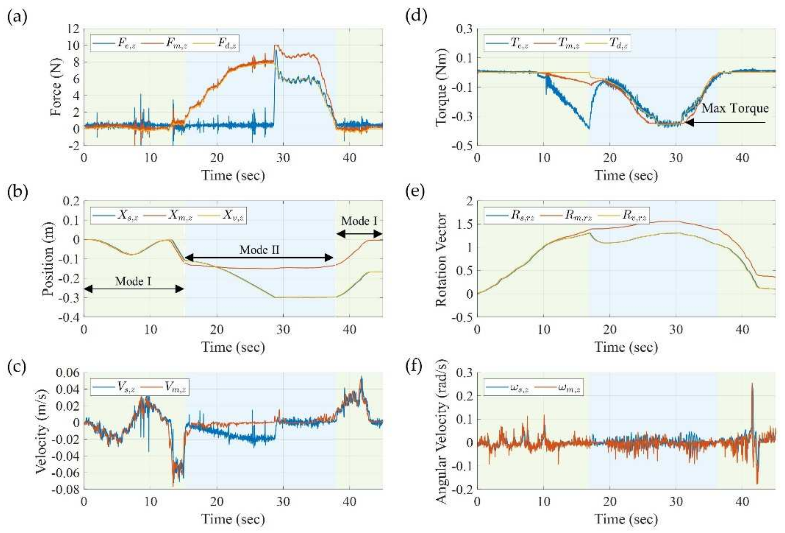
4.2. Switching of Hybrid Control

To more clearly show the force on the end of the manipulator, as well as the changes in displacement and velocity during the control-switching process, we teleoperated the remote arm to touch the environment. The whole process consisted of transition from the admittance control mode to the speed control mode, finally, switching back to the admittance control mode. The results are shown in Figure 6.
The key parameters used in the experiments were as follows. For the admittance control parameters, the displacement direction showed M A = 1 , D A = 100 , and K A = 300 , and the rotation direction showed M A = 1 , D A = 100 , and K A = 300 . For the parameters of the speed control, the conversion factor of force and linear velocity was 1 / 300 , and the conversion factor of torque and the rotation vector was 1 / 10 . For the virtual potential field parameters, k p = 500 , k v = 10 , k x = 2.0 , and k z = 2.0 . Regarding the mapping coefficient k e of the environmental contact force in the haptic device, the coefficients of force and torque were 0.5 and 0.2, respectively.
For the admittance control stage without force, see Mode I in Figure 6a−c, where F e , z is essentially kept at 0. However, due to the movement of the manipulator, the sensor value fluctuated when the acceleration changed greatly.
In this phase, the displacement and rotation of the end of the remote manipulator followed the master handle, and the linear and angular velocities remained consistent, as shown in Figure 6b−e. After entering the speed control stage, the displacement and speed of the master hand and the remote arm became inconsistent, as shown in Mode II in a−c. In this mode, V s , z F d , z F e , z , the movement stopped after F d , z = F e , z , and the environmental contact force F e , z at the end followed F d , z . After moving in the opposite direction and switching back to the admittance control, the displacement difference and velocity of the master and remote ends were consistent again, as shown in the second section of Mode I in b and c. The difference between rotation and translation was that rotation was affected by T e , z in the admittance control stage. As the expected rotation vector R m , r z input by the master hand increased, the R s , r z of the remote arm also increased. However, due to the existence of T e , z , there was deviation e R between the two, as shown in Mode I in d and e. When switching to the speed control, as shown in Mode II, since the desired torque T d , z on the switching boundary was 0 Nm, which was smaller than the current environmental torque T e , z , reverse rotation occurred, and the contact torque T e , z decreased. As the desired torque T d , z increased or decreased, a corresponding rotation occurred from the end of the manipulator, and T e , z followed the change of T d , z . The output force τ ^ m W 6 of the master haptic device was set to a maximum value. If the result of (15) exceeded the set maximum value, then the output force was output according to the maximum value of τ ^ m W , such as (d), at the maximum torque.

4.3. Influence of Admittance Control Parameters

This section compares the response differences when the external force had the same step-change under different admittance control parameters. In the experiment, we set the environment contact virtual force in the z-axis direction of F W on the force sensor, as shown by the yellow dotted line in Figure 7a−c. The force and displacement of the end of the manipulator in the z-direction in F W for different groups are shown in Figure 7d−f. The experiments were divided into three groups, each of which had only a single changed admittance control parameter. In Figure 7a−c, the desired extra force F n , z was consistent, but the actual force fluctuated due to changes in acceleration caused by the movement of the robotic arm. The greater the end-load and acceleration, the greater the fluctuation in the force sensor value. Figure 7d−f shows the response of the robot arm in the z-direction displacement of F W under the above force step signal. A comparison of the dotted and solid lines shows that the designed admittance control system was consistent with the simulation results.
The phase difference shows that the execution delay of the robotic arm was about 240 ms. Under the premise of system stability, K A determined the offset of the displacement after stabilization. D A and M A affected the time to reach a steady state, that is, the magnitude of the acceleration. The larger D A and M A were, the longer the system took to reach a steady state. Together, K A , D A , and M A determined the stability of this second-order system. The response curve for displacement depended on whether the system was overdamped, underdamped, or critically damped, as shown in Figure 7f. It is noteworthy that since the controller in the experiment was a discrete control system realized at a frequency of 125 Hz, when the damping D A was large relative to K A and M A , it caused instability of the system.

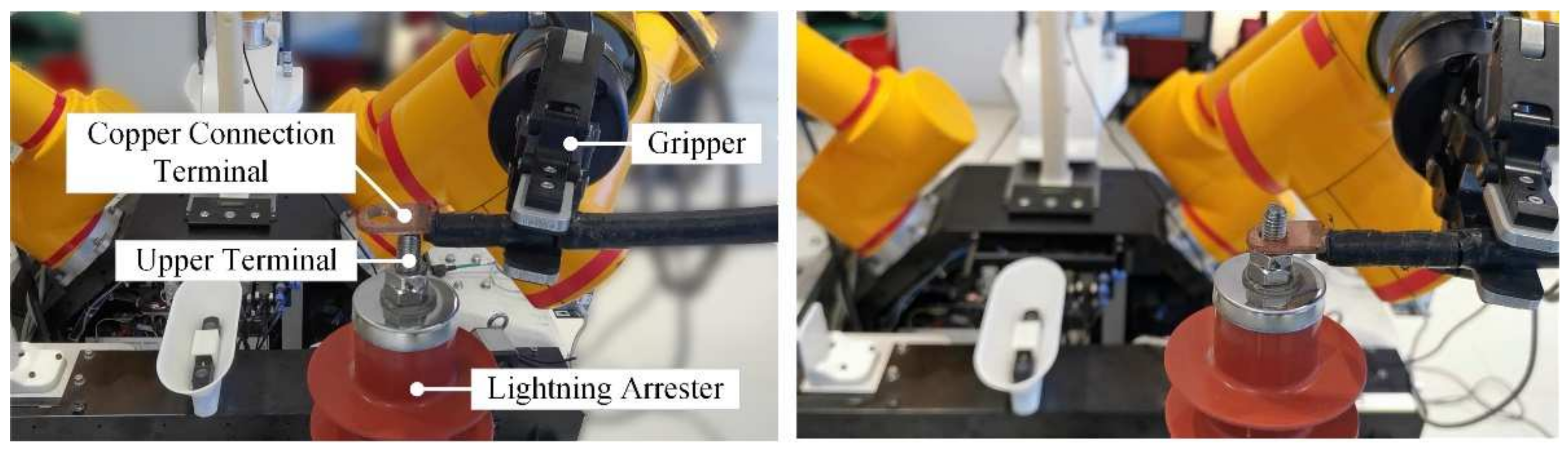
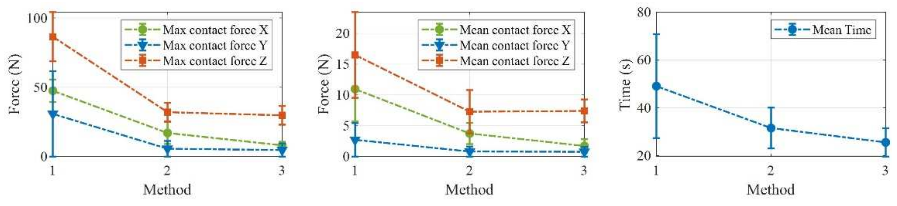
4.4. Application in PDLOR

The replacement of a lightning arrester in live-line work of a distribution network is an important task. In the installation of a lightning arrester, it is necessary to install wire with a copper connection terminal to the upper terminal on the lightning arrester, as shown in Figure 8. An upper terminal consists of a section of M10 stud with a maximum outer diameter of about 9.96 mm, and the through-hole of a copper terminal is about 10.5 mm. In addition, when a wire is clamped, there is a certain amount of stress between the wire and the gripper, making it very difficult for a robot to perform the assembly. When remote-operated peg-hole assembly is performed with only visual feedback, it can easily cause a robot to be overstressed, causing a protective stop.
We completed the process of performing teleoperated perforation under the conditions of weak feedback, bilateral control, and hybrid control.
We compared teleoperated perforation processes under no force feedback, bilateral control, and hybrid control conditions. First, make the subjects familiar with the teleoperation mode, and then the experiment was conducted after training. Each subject carries out 60 assembly tasks in each teleoperation mode, a total of 180 times per person in three modes. A total of five healthy adults (four males and one female) participated in this study. A protective stop of the robot is considered as assembly failure. The results of the experiment are shown in Figure 9. Among them, the success rate of teleoperation assembly under hybrid control is the highest, which is 98%. The success rate of bilateral control was 96%, and the teleoperation without force feedback mode was the lowest, with a success rate of only 63%. In the assembly process, the contact force of powerless feedback is the largest. The hybrid control of contact force in X and Y direction is lower than that in bilateral control, which means that the assembly is smoother. The contact force in Z direction is similar, but the hybrid control is relatively more stable. From the analysis of the average assembly time, the hybrid control time is shorter and the efficiency is higher. Figure 9 shows the data for a typical successful assembly process under hybrid control conditions, mainly including the displacement data of the master–slave manipulator in F W in the three directions of x, y, and z and the force data of the z-direction.
The whole assembly process included the six stages of (a)−(e), as shown in Figure 10. In stages (a) and (b), since the other end of the wire was fixed, although the terminals were not in contact, there was a certain amount of stress between the gripper and the wire that changed with the movement of the gripper. Stage (c) was the alignment stage for the peg-hole assembly, and F d , z in F W , which was generated by the virtual potential field, fluctuated roughly in the range of 6–7 N, as shown in Figure 10. At the same time, the x and y direction imparted a certain value of F d so that the end could be fine-tuned in the X O Y plane until the peg-hole was aligned. In this stage, X s , z fluctuated in a range that was imperceptible to the naked eye, and the contact force F e , z also fluctuated in the range of 3−10 N. The starting time of stage (d) was T 1 , and the ending time was T 2 . In this stage, the copper connection terminal descended along the stud under the action of the desired force. There was relatively obvious displacement in the z-direction, and the main force was the stress of the wire. At T 2 , the copper terminal reached the bottom of the upper terminal of the arrester, and F e , z increased instantly. During stage (e), F d , z decreased, and both X s , z and F e , z from the end of the manipulator tended to be stable. Stage (d) started the release of the gripper, and F e , z tended toward 0 N.

5. Conclusions

We proposed a hybrid control method that took into account both large-scale teleoperation and fine-scale local operation with a master–slave teleoperation system when the workspace of the master hand was much smaller than that of the remote arm. We applied this control strategy to a distribution network live-line working robot so that the robot could perform tasks involving physical interaction with the operation target. Remote binocular visual feedback rendered through a VR HMD and haptic feedback from remote force sensors greatly reduced the transparency of the teleoperation system.
Through the parameter identification of the end load, we can accurately obtain the contact force between the tool and the environment. The maximum force and torque deviations are 0.513 N and 0.036 Nm, respectively. We analyze the switching process of the hybrid control strategy and test the influence of the change of admittance parameters on the remote system. The response of the system is consistent with the simulation results in Simulink. Through the phase difference analysis of the displacement curve, the dynamic tracking delay of the teleoperation system is about 240 ms.
The upper lead assembly was completed during the installation of an arrester, which is difficult in live-line operations on distribution networks. The experiment proves that the hybrid teleoperation control can effectively complete the shaft-hole assembly operation under less contact force compared with other methods. The average assembly time is the lowest, about 25 s.
However, the method presented some limitations, which are summarized here. First, the calculation of additional force did not consider the influence of acceleration on the force sensor, and the estimation of additional force may cause a certain amount of error for a heavy tool. In addition, there are processes that cannot maintain a constant contact force during the switching process, such as processes in which the expected force at the switching boundary is 0 N, which can be optimized in the future. Finally, the PDLOR is transported to overhead lines by a bucket truck during actual operation, causing the robot itself to vibrate with a low frequency and a small amplitude. We plan to further verify the performance of the teleoperation system outdoors.

Author Contributions

Conceptualization, E.D. and Y.C.; methodology, Y.C.; software, Y.C. and Y.W.; investigation, K.W. and Y.Z.; writing—original draft preparation, Y.C. and Y.W.; writing—review and editing, E.D.; project administration, R.G. and S.W.; funding acquisition, E.D. and X.T. All authors have read and agreed to the published version of the manuscript.

Funding

The work is supported by the State Grid Anhui Science and Technology Project (5212F0200125) and the National Key Research and Development Program of China (2018YFB1307400).

Data Availability Statement

The data that support the findings of this study are available from the corresponding author upon reasonable request.

Conflicts of Interest

The authors declare no conflict of interest.

References

  1. Gu, J.; Zhang, P. Research on Safety Risk Management and Control of Live Work in Distribution Networks. In Proceedings of the IOP Conference Series: Materials Science and Engineering, Ulaanbaatar, Mongolia, 10–13 September 2020; p. 32106. [Google Scholar]
  2. Zhao, H.; Wang, C.; Guo, R.; Rong, X.; Guo, J.; Yang, Q.; Yang, L.; Zhao, Y.; Li, Y. Autonomous live working robot navigation with real-time detection and motion planning system on distribution line. High Volt. 2022. [Google Scholar] [CrossRef]
  3. Allan, J.-F. Robotics for distribution power lines: Overview of the last decade. In Proceedings of the 2012 2nd International Conference on Applied Robotics for the Power Industry (CARPI), Zurich, Switzerland, 11–13 September 2012; pp. 96–101. [Google Scholar]
  4. Chen, Y.; Zhang, B.; Zhou, J.; Wang, K. Real-time 3D unstructured environment reconstruction utilizing VR and Kinect-based immersive teleoperation for agricultural field robots. Comput. Electron. Agric. 2020, 175, 105579. [Google Scholar] [CrossRef]
  5. Du, G.; Deng, Y.; Ng, W.W.Y.; Li, D. An Intelligent Interaction Framework for Teleoperation Based on Human-Machine Cooperation. IEEE Trans. Hum.-Mach. Syst. 2022, 52, 963–972. [Google Scholar] [CrossRef]
  6. Stotko, P.; Krumpen, S.; Schwarz, M.; Lenz, C.; Behnke, S.; Klein, R.; Weinmann, M. A VR System for Immersive Teleoperation and Live Exploration with a Mobile Robot. arXiv 2019, arXiv:1908.02949. [Google Scholar]
  7. Lipton, J.I.; Fay, A.J.; Rus, D. Baxter’s Homunculus: Virtual Reality Spaces for Teleoperation in Manufacturing. IEEE Robot. Autom. Lett. 2018, 3, 179–186. [Google Scholar] [CrossRef] [Green Version]
  8. Li, R.; Wang, H.; Liu, Z. Survey on Mapping Human Hand Motion to Robotic Hands for Teleoperation. IEEE Trans. Circuits Syst. Video Technol. 2022, 32, 2647–2665. [Google Scholar] [CrossRef]
  9. Ajoudani, A.; Tsagarakis, N.; Bicchi, A. Tele-impedance: Teleoperation with impedance regulation using a body–machine interface. Int. J. Robot. Res. 2012, 31, 1642–1656. [Google Scholar] [CrossRef]
  10. Girbes-Juan, V.; Schettino, V.; Demiris, Y.; Tornero, J. Haptic and Visual Feedback Assistance for Dual-Arm Robot Teleoperation in Surface Conditioning Tasks. IEEE Trans. Haptics 2021, 14, 44–56. [Google Scholar] [CrossRef]
  11. Peppoloni, L.; Brizzi, F.; Avizzano, C.A.; Ruffaldi, E. Immersive ROS-integrated framework for robot teleoperation. In Proceedings of the 2015 IEEE Symposium on 3D User Interfaces (3DUI), Arles, France, 23–24 March 2015. [Google Scholar]
  12. Whitney, J.P.; Chen, T.; Mars, J.; Hodgins, J.K. A hybrid hydrostatic transmission and human-safe haptic telepresence robot. In Proceedings of the International Conference on Robotics and Automation, Stockholm, Sweden, 16–21 May 2016; pp. 690–695. [Google Scholar]
  13. Herdocia, A.H.; Shademan, A.; Jägersand, M. Unimodal asymmetric interface for teleoperation of mobile manipulators: A user study. In Proceedings of the 2012 IEEE/RSJ International Conference on Intelligent Robots and Systems, Vilamoura-Algarve, Portugal, 7–12 October 2012; pp. 5214–5219. [Google Scholar]
  14. Gao, X.; Silverio, J.; Pignat, E.; Calinon, S.; Li, M.; Xiao, X. Motion Mappings for Continuous Bilateral Teleoperation. IEEE Robot. Autom. Lett. 2021, 6, 5048–5055. [Google Scholar] [CrossRef]
  15. Li, G.; Caponetto, F.; Del Bianco, E.; Katsageorgiou, V.; Sarakoglou, I.; Tsagarakis, N.G. Incomplete Orientation Mapping for Teleoperation With One DoF Master-Slave Asymmetry. IEEE Robot. Autom. Lett. 2020, 5, 5167–5174. [Google Scholar] [CrossRef]
  16. Zhou, S.; Shen, C.; Zhu, S.; Li, W.; Nie, Y.; Chen, Z. A Teleoperation Framework Based on Heterogeneous Matching for Hydraulic Manipulator. Machines 2022, 10, 536. [Google Scholar] [CrossRef]
  17. Liu, G.; Geng, X.; Liu, L.; Wang, Y. Haptic based teleoperation with master-slave motion mapping and haptic rendering for space exploration. Chin. J. Aeronaut 2019, 32, 723–736. [Google Scholar] [CrossRef]
  18. Deng, H.; Gong, D.; Yu, J.; Zuo, G. Research on Intuitive Tele-operation Motion Mapping Algorithm for Omnidirectional Mobile Heterogeneous Slave Arm System. In Proceedings of the 2020 10th Institute of Electrical and Electronics Engineers International Conference on Cyber Technology in Automation, Control, and Intelligent Systems (CYBER), Xi’an, China, 10–14 October 2020; pp. 67–72. [Google Scholar]
  19. Li, Z.; Zhang, E.; Zhai, B.; Li, B. Master-Slave Arm Heterogeneous Mapping With Link Pose Constraint in Teleoperation System. IEEE Access 2022, 10, 107202–107213. [Google Scholar] [CrossRef]
  20. Gong, D.; Wang, Y.; Yu, J.; Zuo, G. Motion mapping from a human arm to a heterogeneous excavator-like robotic arm for intuitive teleoperation. In Proceedings of the 2019 IEEE International Conference on Real-time Computing and Robotics (RCAR), Irkutsk, Russia, 4–9 August 2019; pp. 493–498. [Google Scholar]
  21. Yan, Y.; Jiang, W.; Zou, D.; Quan, W.; Li, H.J.; Lei, Y.; Zhou, Z.f. Research on mechanism configuration and coordinated control for power distribution network live working robot. Ind. Robot. Int. J. Robot. Res. Appl. 2020, 47, 453–462. [Google Scholar] [CrossRef]
  22. Wu, W.; Zhou, H.; Guo, Y.; Wu, Y.; Guo, J. Peg-in-hole assembly in live-line maintenance based on generative mapping and searching network. Robot. Auton. Syst. 2021, 143, 103797. [Google Scholar] [CrossRef]
  23. Feng, J.; Zhang, W. Autonomous Live-Line Maintenance Robot for a 10 kV Overhead Line. IEEE Access 2021, 9, 61819–61831. [Google Scholar] [CrossRef]
  24. Islam, S.; Liu, P.X.; El Saddik, A.; Yang, Y.B. Bilateral Control of Teleoperation Systems With Time Delay. IEEE/ASME Trans. Mechatron. 2015, 20, 1–12. [Google Scholar] [CrossRef]
  25. Bong, J.H.; Choi, S.; Hong, J.; Park, S. Force feedback haptic interface for bilateral teleoperation of robot manipulation. Microsyst. Technol. 2022, 28, 2381–2392. [Google Scholar] [CrossRef]
  26. Liu, Y.-C. Task-space bilateral teleoperation systems for heterogeneous robots with time-varying delays. Robotica 2015, 33, 2065–2082. [Google Scholar] [CrossRef]
  27. Kim, Y.B.; Seok, D.-Y.; Lee, S.Y.; Kim, J.; Kang, G.; Kim, U.; Choi, H.R. 6-Axis Force/Torque Sensor With a Novel Autonomous Weight Compensating Capability for Robotic Applications. IEEE Robot. Autom. Lett. 2020, 5, 6686–6693. [Google Scholar] [CrossRef]
  28. Johansen, T.A.; Zolich, A.; Hansen, T.; Sorensen, A.J. Unmanned aerial vehicle as communication relay for autonomous underwater vehicle—Field tests. In Proceedings of the 2014 IEEE Globecom Workshops (GC Wkshps), Austin, TX, USA, 8–12 December 2014. [Google Scholar]
  29. Ott, C.; Mukherjee, R.; Nakamura, Y. Unified Impedance and Admittance Control. In Proceedings of the 2010 IEEE International Conference on Robotics and Automation, Anchorage, AK, USA, 3–7 May 2010. [Google Scholar]
  30. Michel, Y.; Rahal, R.; Pacchierotti, C.; Giordano, P.R.; Lee, D. Bilateral Teleoperation With Adaptive Impedance Control for Contact Tasks. IEEE Robot. Autom. Lett. 2021, 6, 5429–5436. [Google Scholar] [CrossRef]
Figure 1. Framework diagram of a force feedback teleoperation system combined with virtual reality. On the left is the master control terminal, which is usually located in the ground cockpit. On the right is the PDLOR. When working, the PDLOR is loaded into the insulated working bucket of a bucket truck and raised to the overhead line for operation.
Machines 11 00002 g001
Figure 2. Summary block diagram of the bilateral teleoperation hybrid control system. The figure only illustrates the hybrid control in the displacement direction, which is similar to the rotation direction. The two control modes can be switched based on whether the current position of the main hand is within the set workspace.
Machines 11 00002 g002
Figure 3. Torque generation of the haptic device on the master end in the direction of rotation. (a) Rotation constraint. (b) Simplified two-dimensional potential field diagram.
Machines 11 00002 g003
Figure 4. Virtual robot and remote camera visual feedback under different visual angles of HMD.
Machines 11 00002 g004
Figure 5. Force sensor data results before equilibration and additional force estimation. The orange line represents the data for τ ^ s versus time, and the blue line represents the additional force τ ^ e x t obtained after balancing the load. The yellow line represents the data obtained by Kalman filtering of the balanced data.
Machines 11 00002 g005
Figure 6. Data analysis diagram of the switching process of the hybrid control. Diagrams (ac) show the changes in physical parameters in the z-direction in F W . Diagrams (df) show the torque around the z-axis and changes in the rotation vector and angular velocity. The period with the light cyan background represents the admittance control stage, referred to as Mode 1. The period with the light blue background is the speed control stage, referred to as Mode 2.
Machines 11 00002 g006
Figure 7. Admittance-shaping step responses under different parameters. Diagrams (af) correspond to three sets of experiments. Diagrams (ac) show the set desired sensor data (dashed line) and the actual force sensor value (solid line). In (df), the dotted lines represent responses under ideal conditions simulated with MATLAB/Simulink, and the solid line are the recorded actual displacements of the end of the manipulator.
Machines 11 00002 g007
Figure 8. Installation experiment of lightning arrester using hybrid control teleoperation by PDLOR.
Machines 11 00002 g008
Figure 9. Comparison of the installation of the lightning arrester under three teleoperation methods. Method 1 refers to teleoperation in the workspace without force feedback. Method 2 refers to bilateral teleoperation. Method 3 refers to force feedback hybrid control.
Machines 11 00002 g009
Figure 10. Data on forces and displacements during arrester assembly. (a) Change of force in z-direction during assembly. (b) Displacement in z-direction during as-sembly. Interval af denote six processes: a. admittance control without touching environment, b. speed control without touching environment, c. copper connection terminal made contact and aligned with lighting arrester upper terminal, d. copper connection terminal descended along stud, e. copper connection terminal touched the bottom of upper terminal, f. gripper was released.
Machines 11 00002 g010
Table 1. Calculated Load identification parameters of the force sensor at the end of the manipulator.
F 0 , x F 0 , y F 0 , z M 0 , x M 0 , y M 0 , z
2.7014−2.88616.27680.0357−0.2755−0.0141
p t , x p t , x p t , z g t , x g t , y g t , z
0.00070.00050.0553−0.08580.0313−10.9563
Disclaimer/Publisher’s Note: The statements, opinions and data contained in all publications are solely those of the individual author(s) and contributor(s) and not of MDPI and/or the editor(s). MDPI and/or the editor(s) disclaim responsibility for any injury to people or property resulting from any ideas, methods, instructions or products referred to in the content.

