Crowning Method on Bearing Supporting Large Wind Turbine Spindle Considering the Flexibility of Structure of Shaft System
Abstract
:1. Introduction
2. FE Modeling Method of the Shaft Assembly
2.1. Bearings Modeling
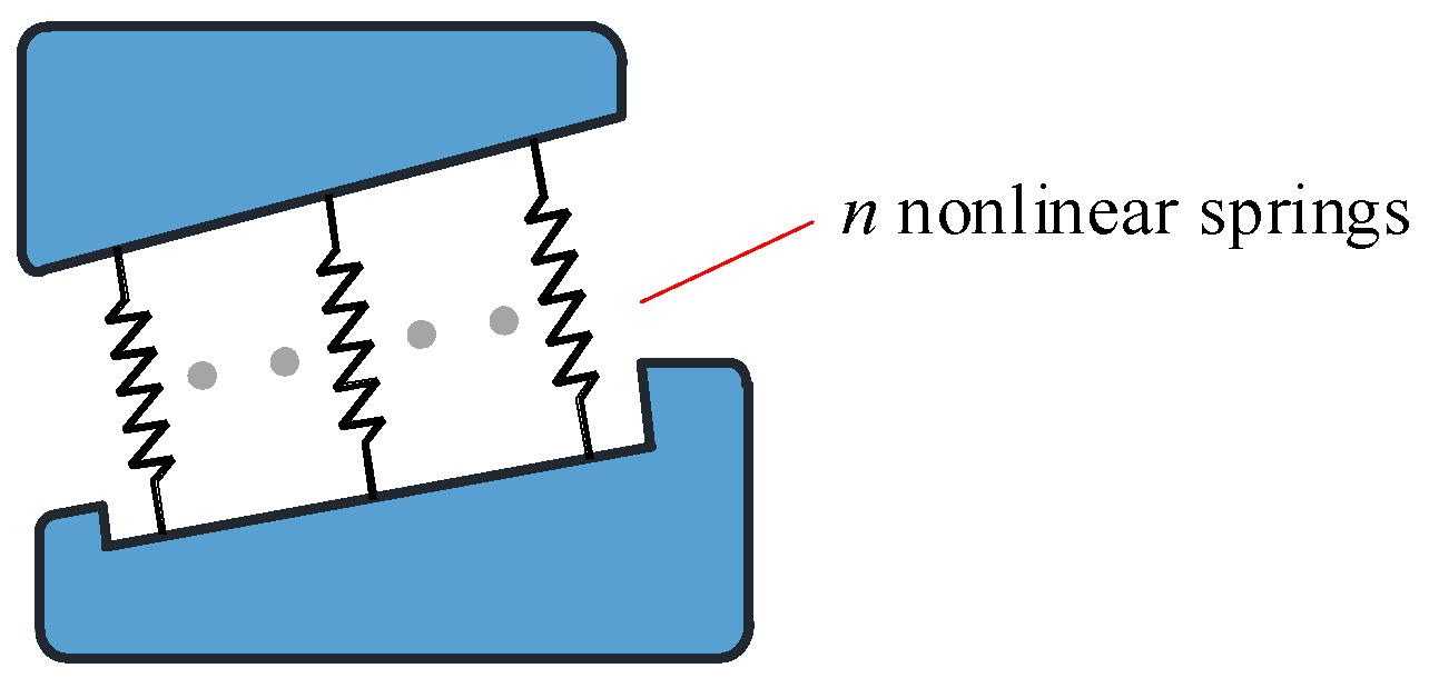
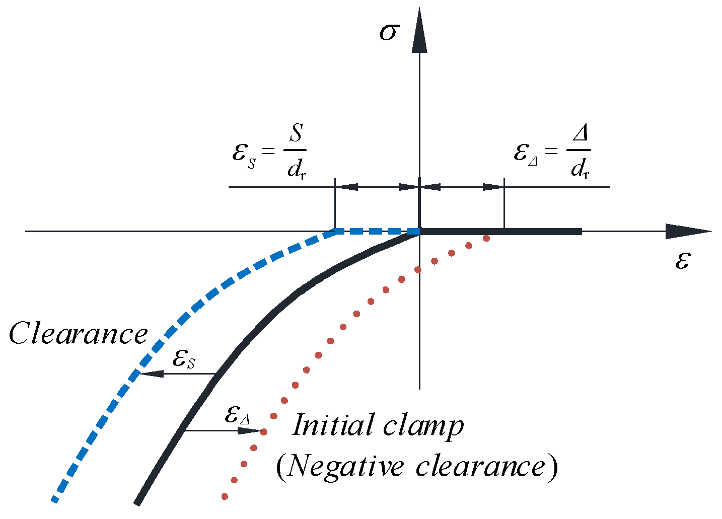
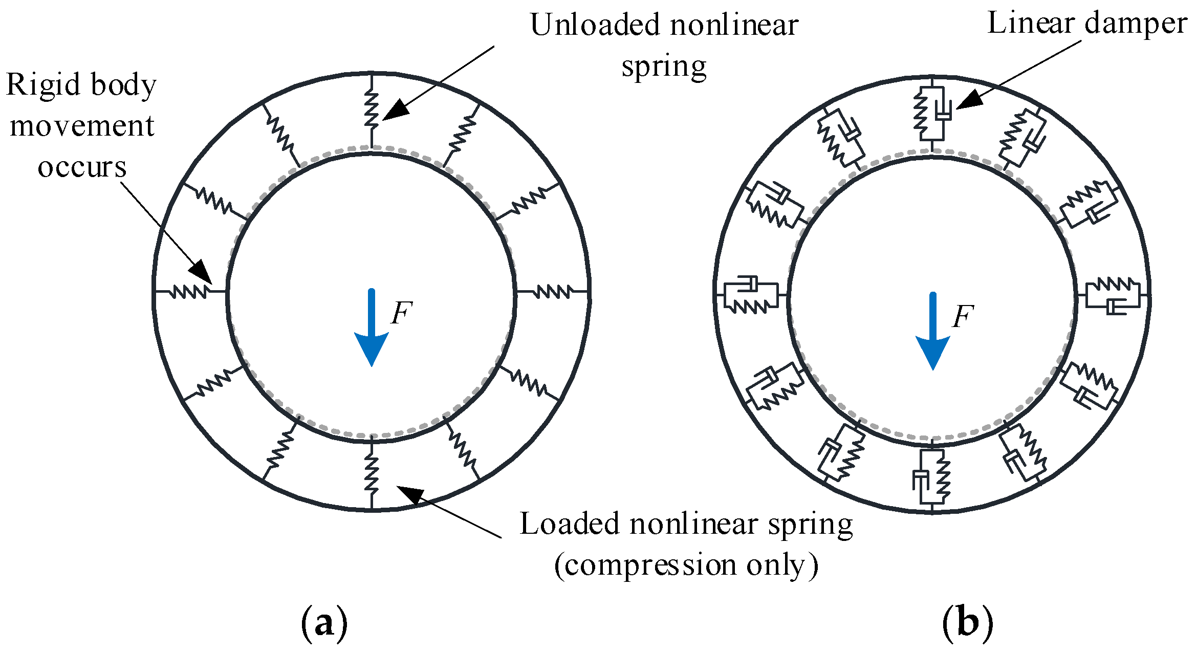
- Nonlinear spring elements with special nonlinear stress-strain characteristics.
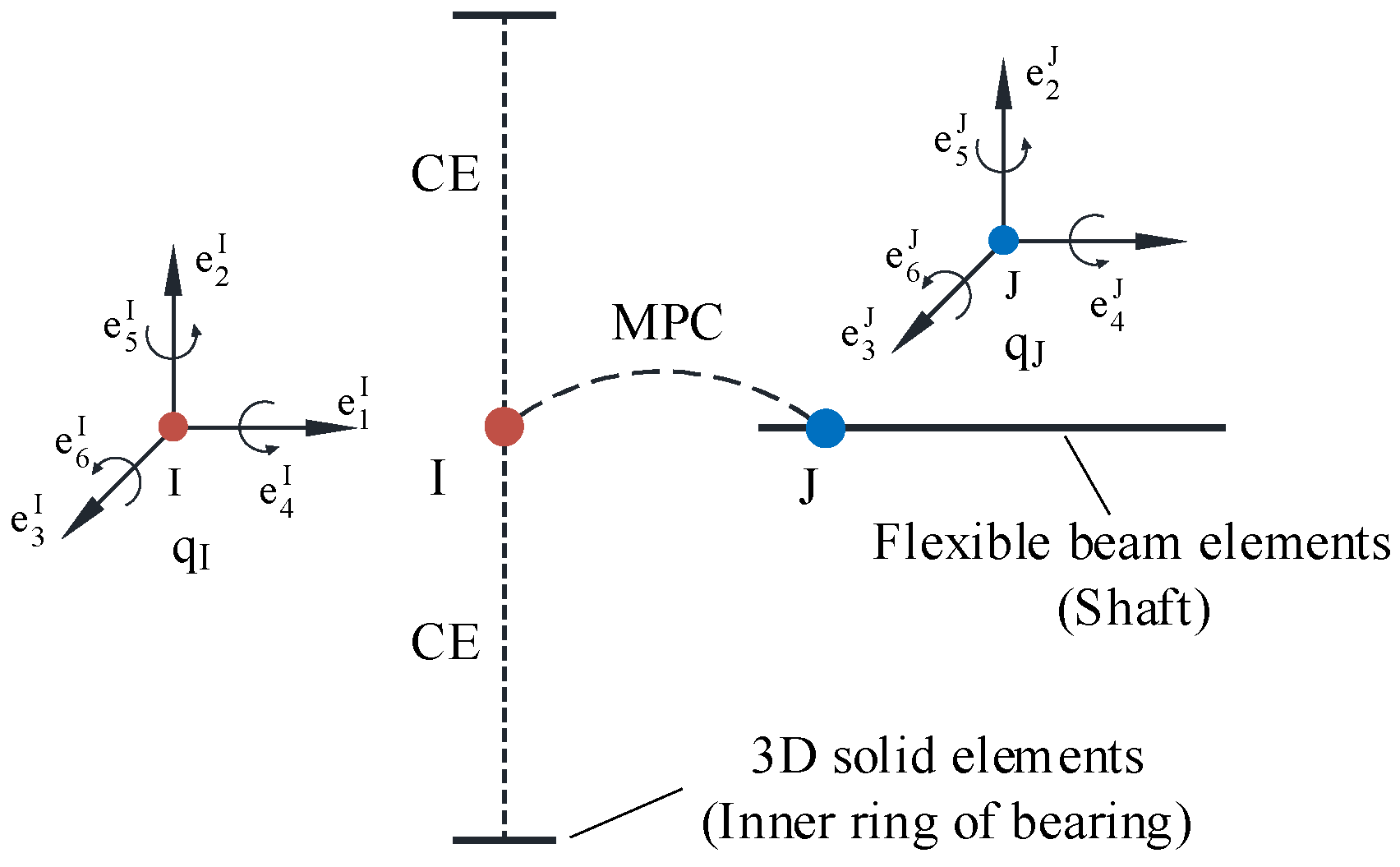
- Superelements with the reduction matrix of structural stiffness.
2.2. Main Shaft Modeling
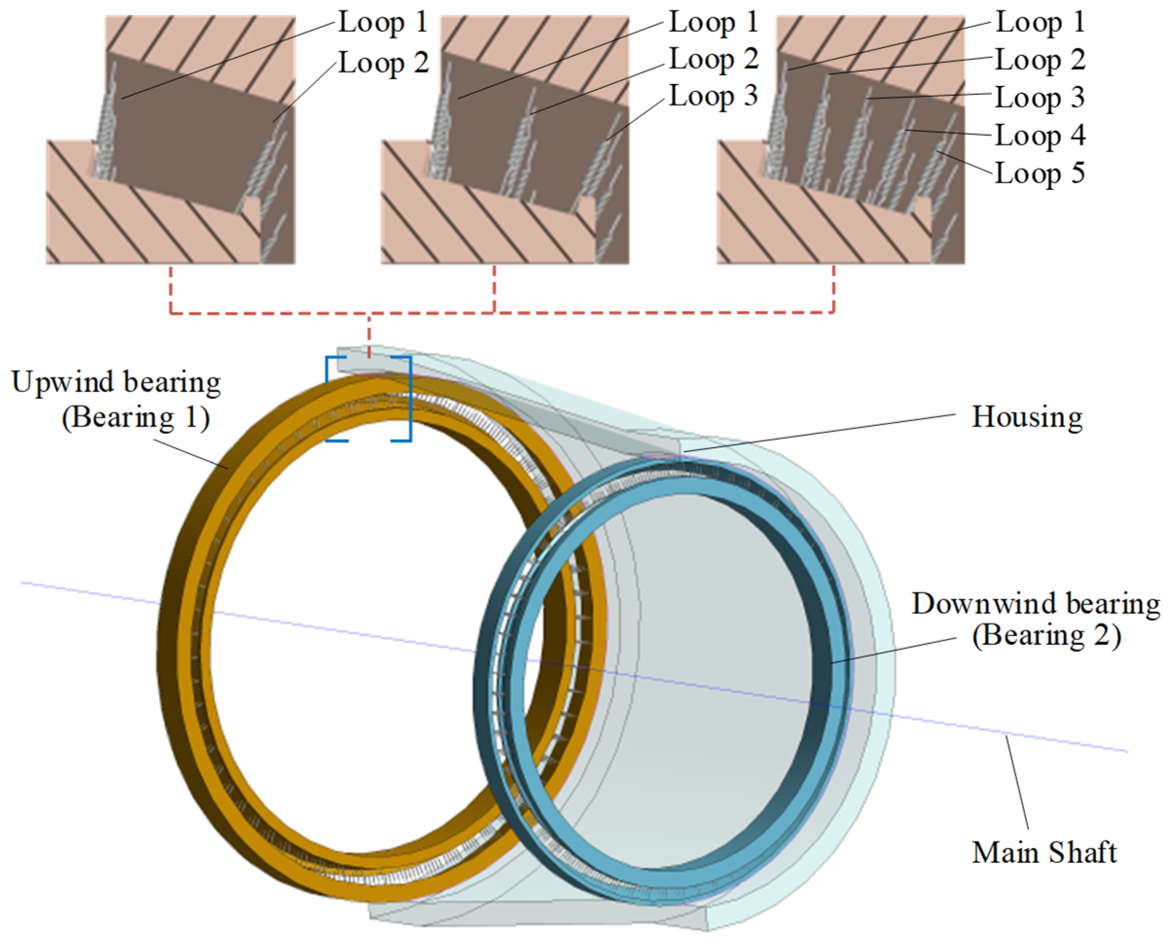
2.3. Housing Modeling
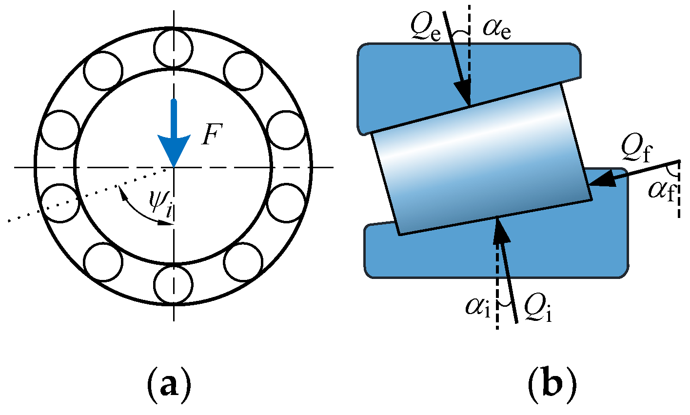
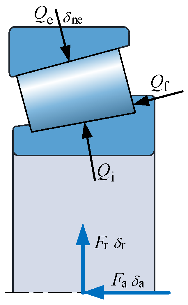
3. Theoretical Calculation of Maximum Roller Load
4. Sub-Model of Bearing
4.1. Logarithmic Crowning of Roller
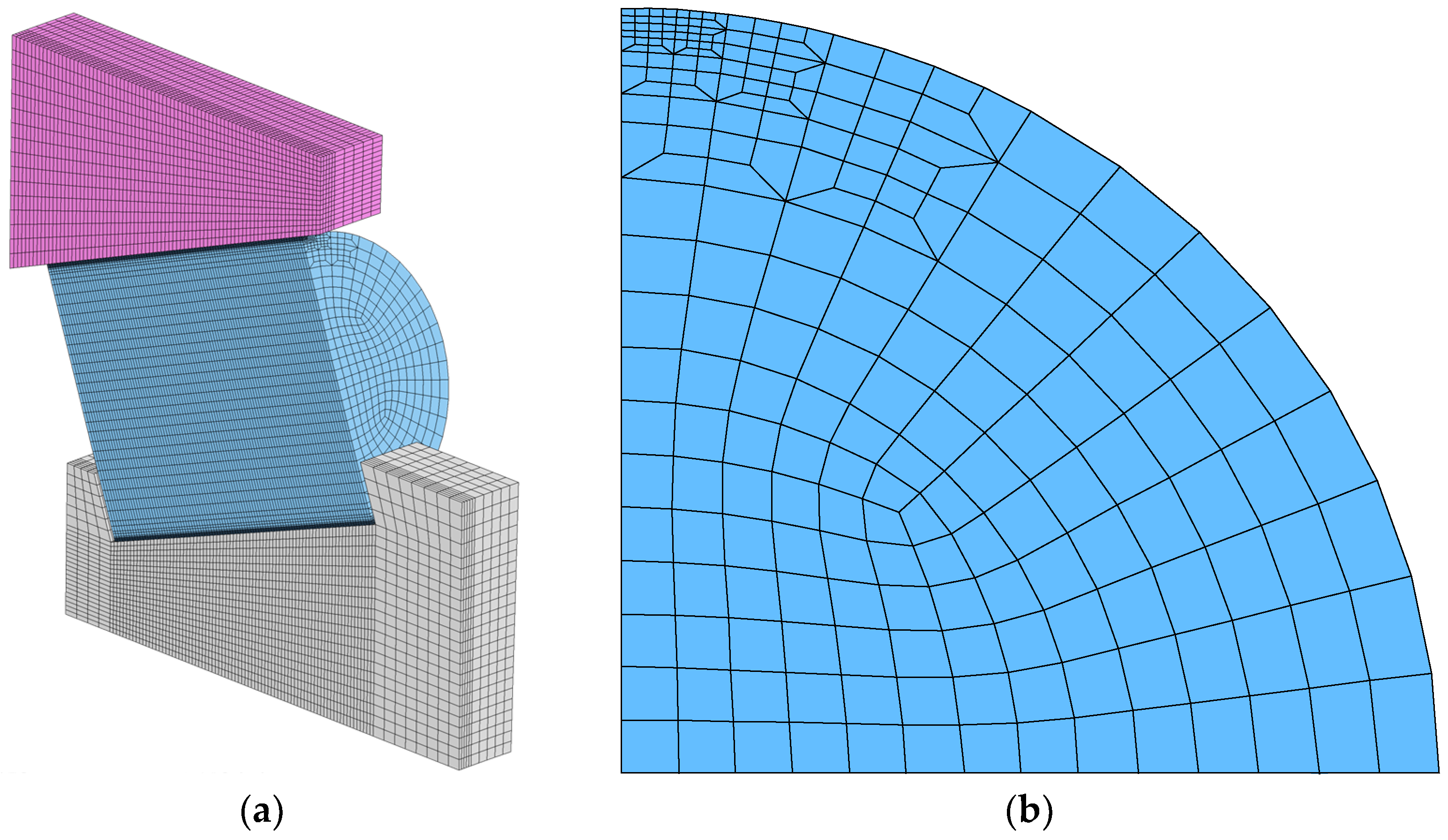
4.2. Mesh of Sub-Model
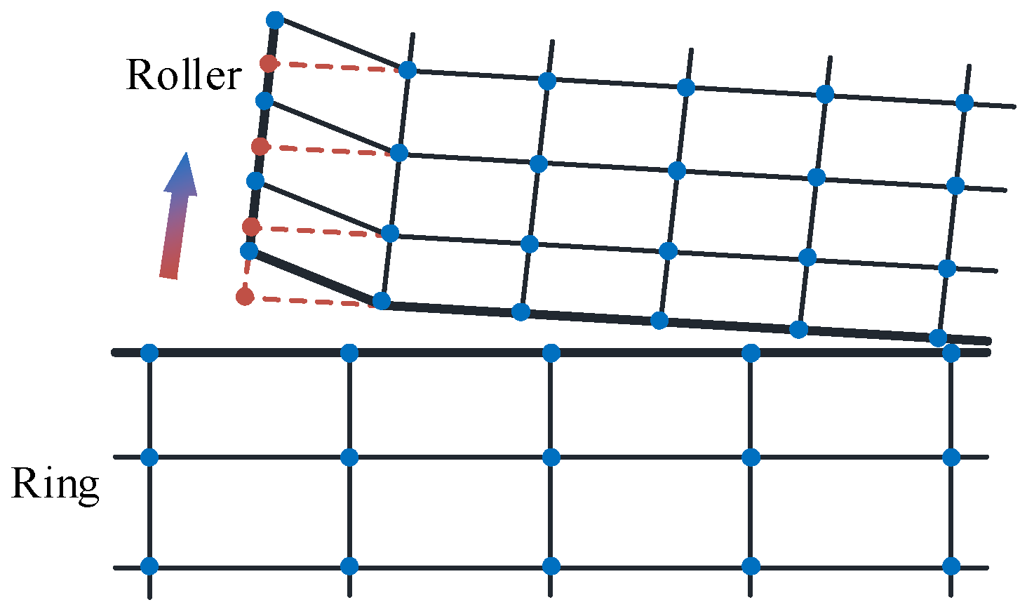
4.3. Boundary Conditions
5. Analysis and Discussion of Results
5.1. Effect of Damping on the Solution of the Shaft System
5.2. Influence of Structural Rigidity on the Shaft System
5.3. Effect of the Quantity of Replacement Springs on the Bearing Load Distribution
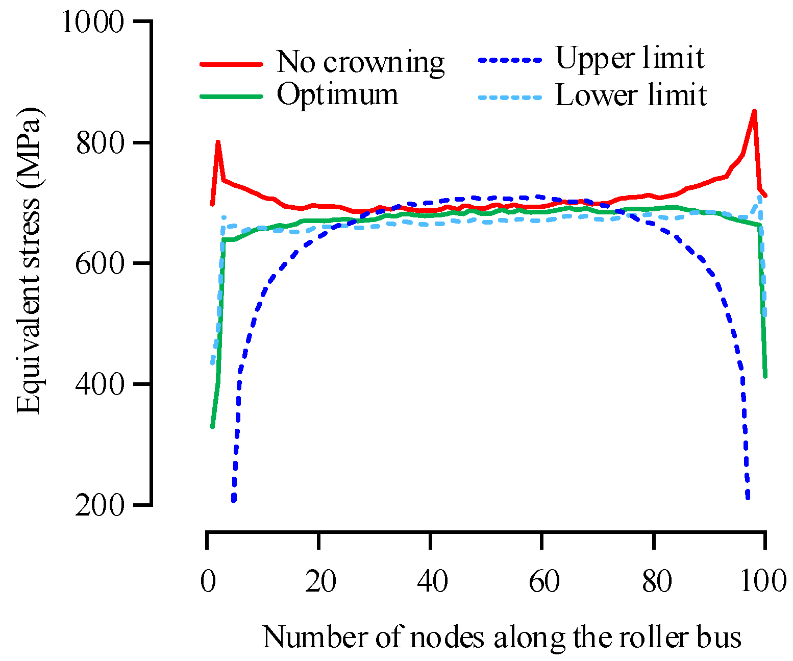
5.4. Design of Optimum Crowning and Its Tolerance of the Roller
6. Conclusions
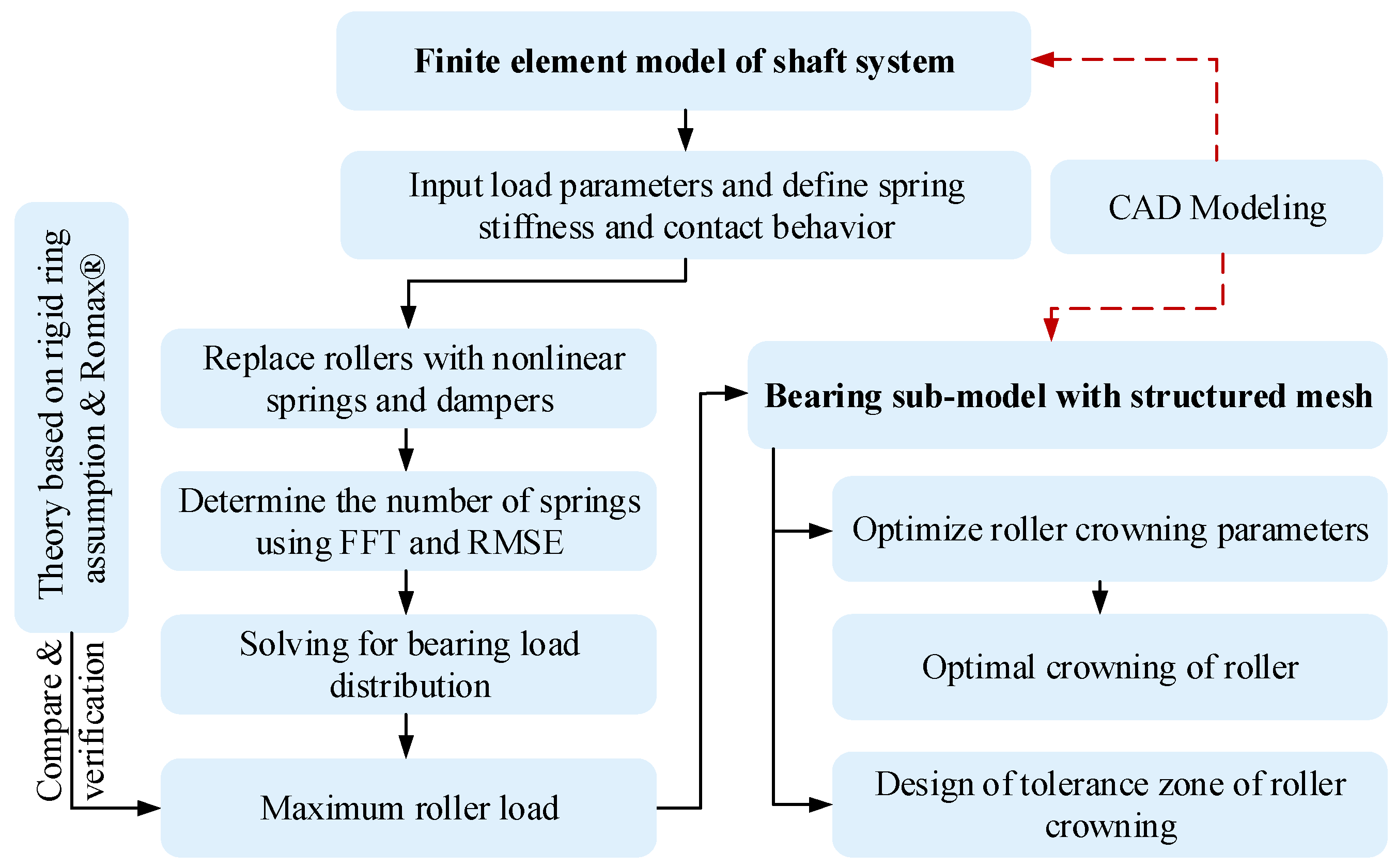
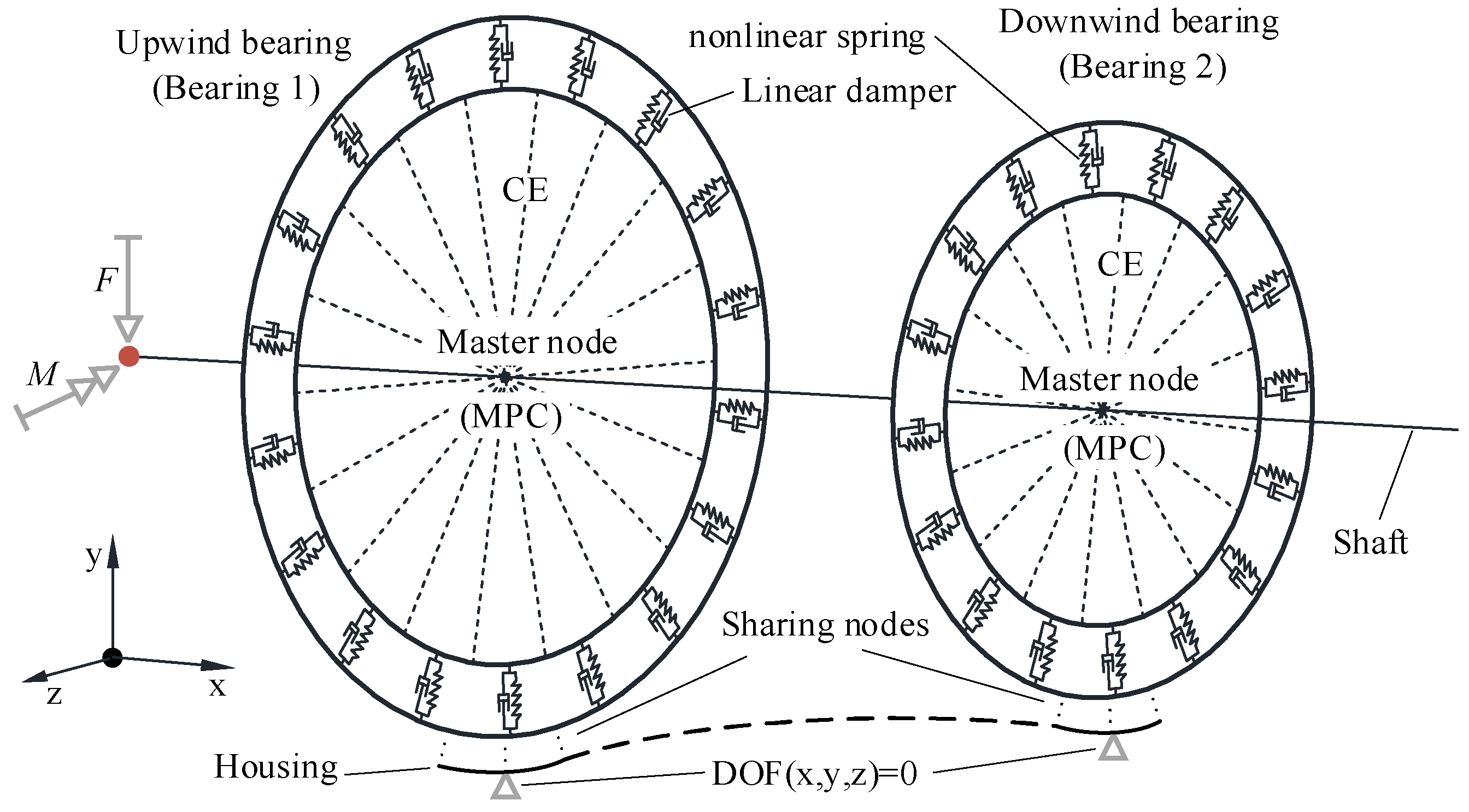
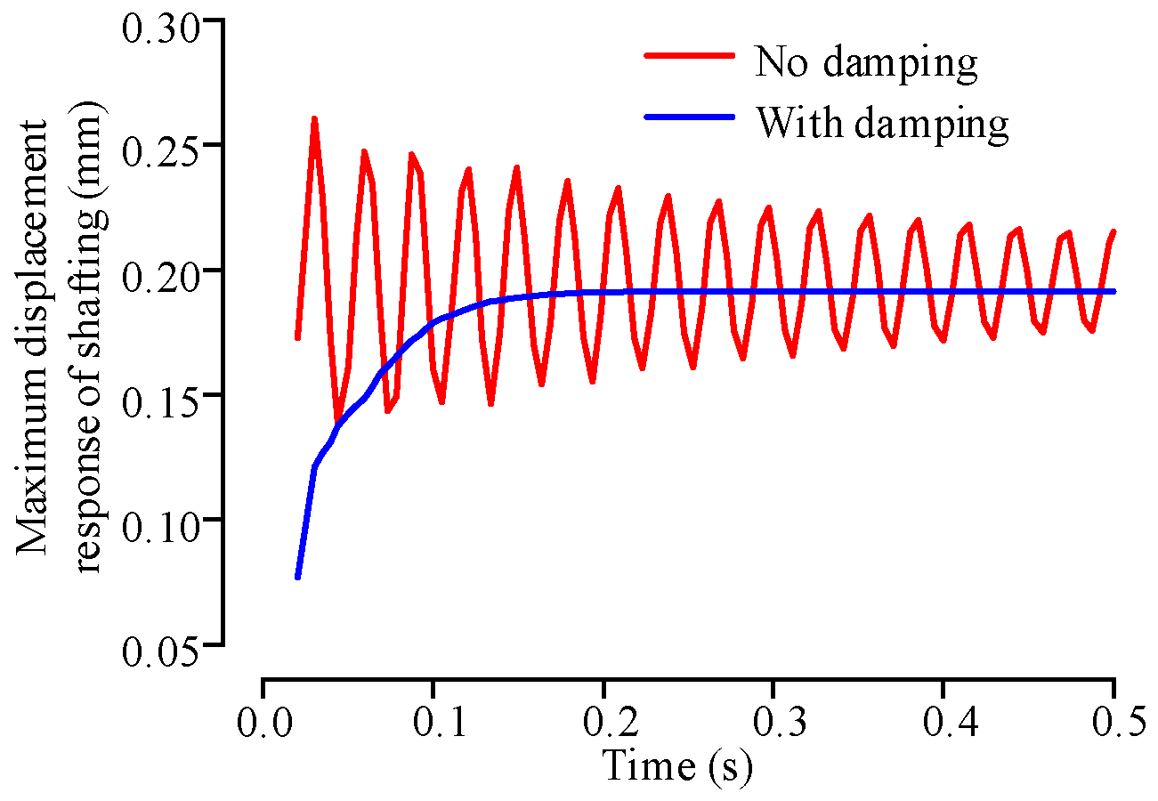
- CE and MPC algorithms were used to connect the shaft and bearing, and nonlinear spring elements and dampers with critical damping were used to replace the rollers to construct the FE model of the shaft assembly. The model has good convergence.
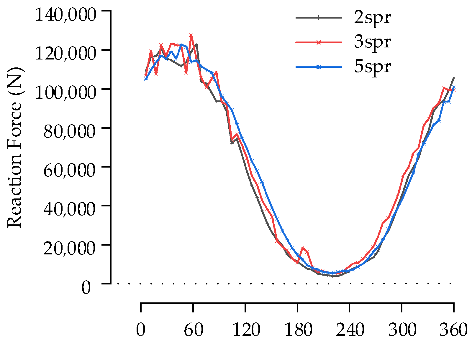
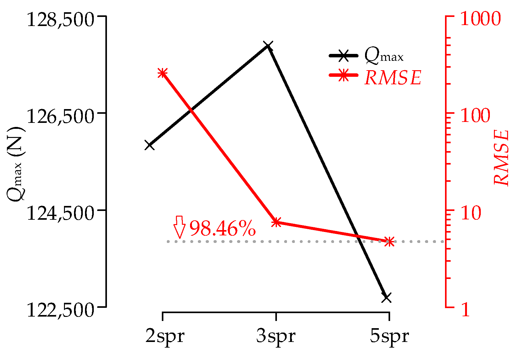
- The high-pass filter based on FFT was used to filter the sequences of spring load distribution and then performed convergence analysis using RMSE, which can obtain the ideal number of replacement springs for each roller.
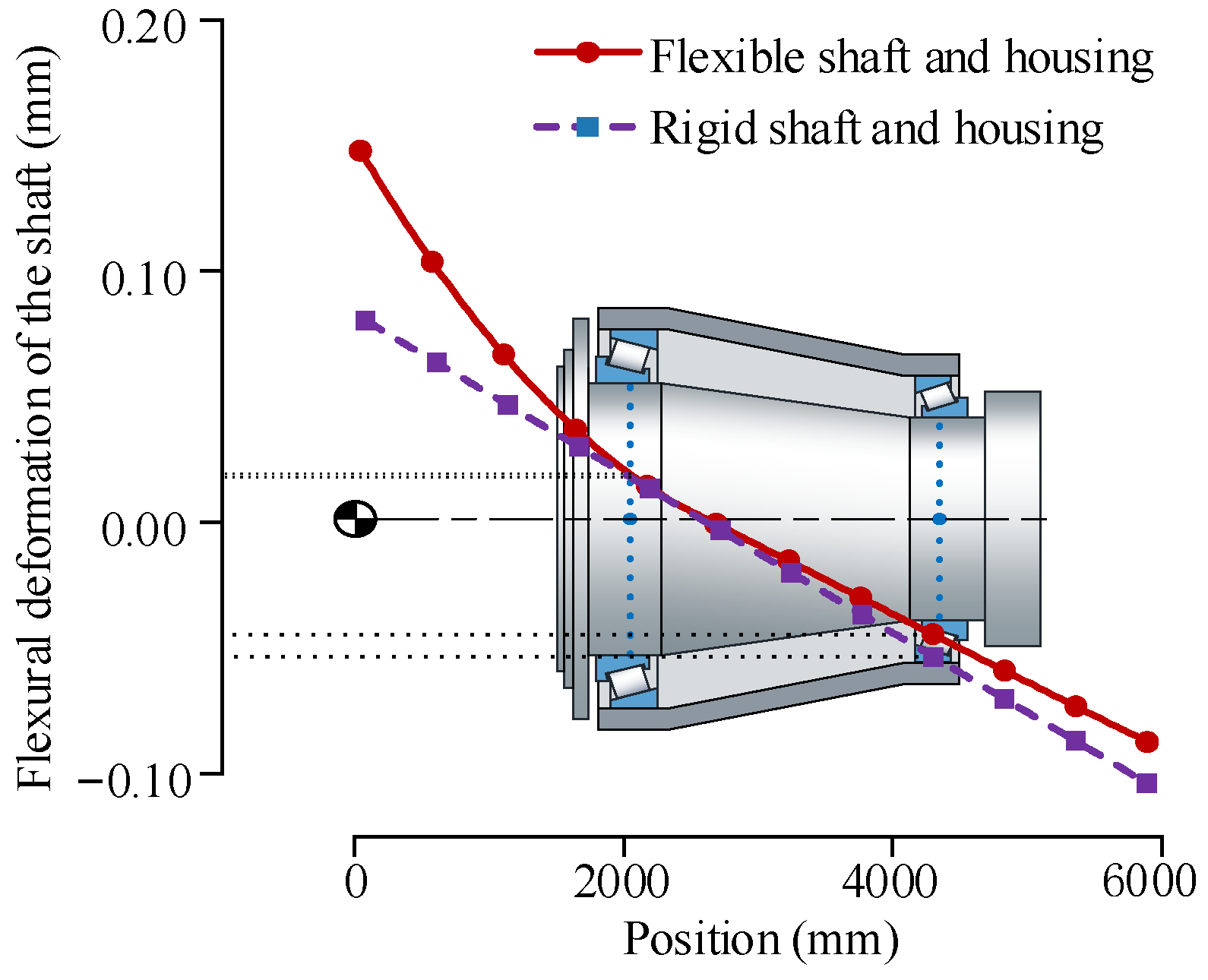
- By analyzing the deformation of the shaft and the relative position of the outer profiles of the outer rings of two bearings, the FE model of the shaft system considering the structure’s flexibility has higher calculation accuracy than the FE model with a rigid structure. The maximum roller load of the FE model with a flexible structure is 15.75% less than the theoretical solution, which is within a reasonable range.
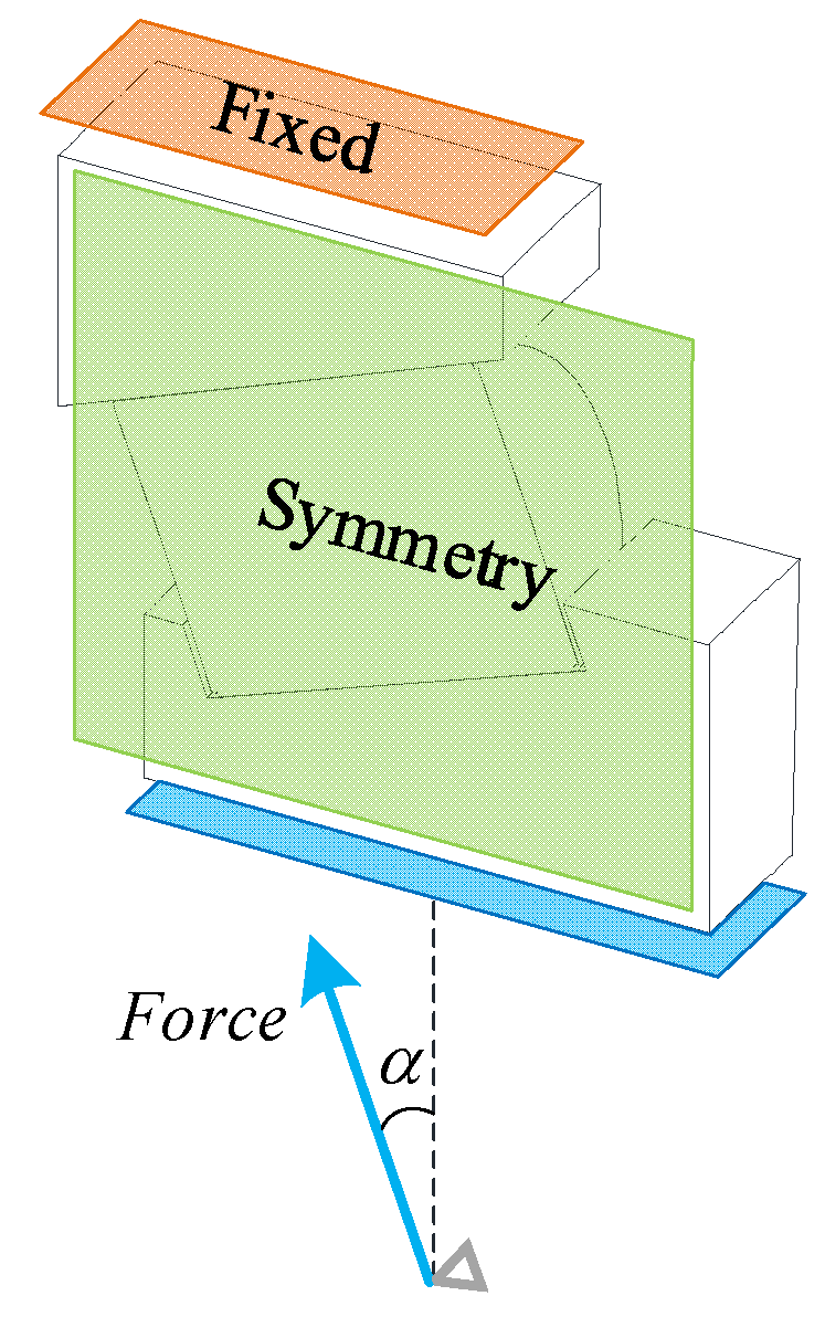
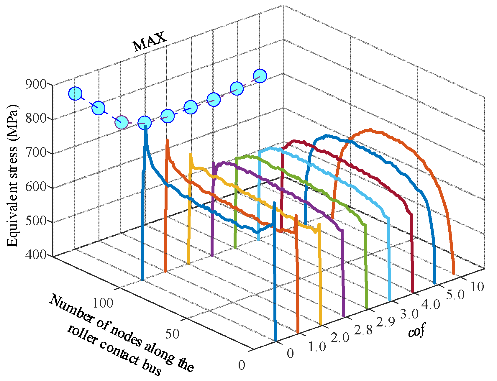
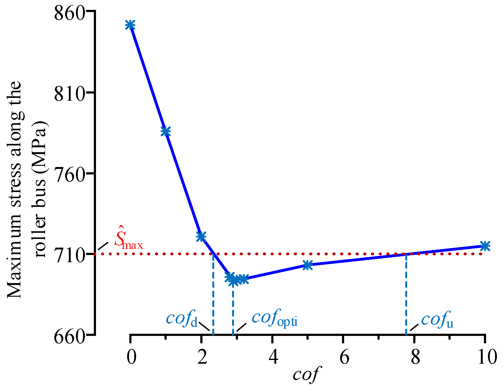
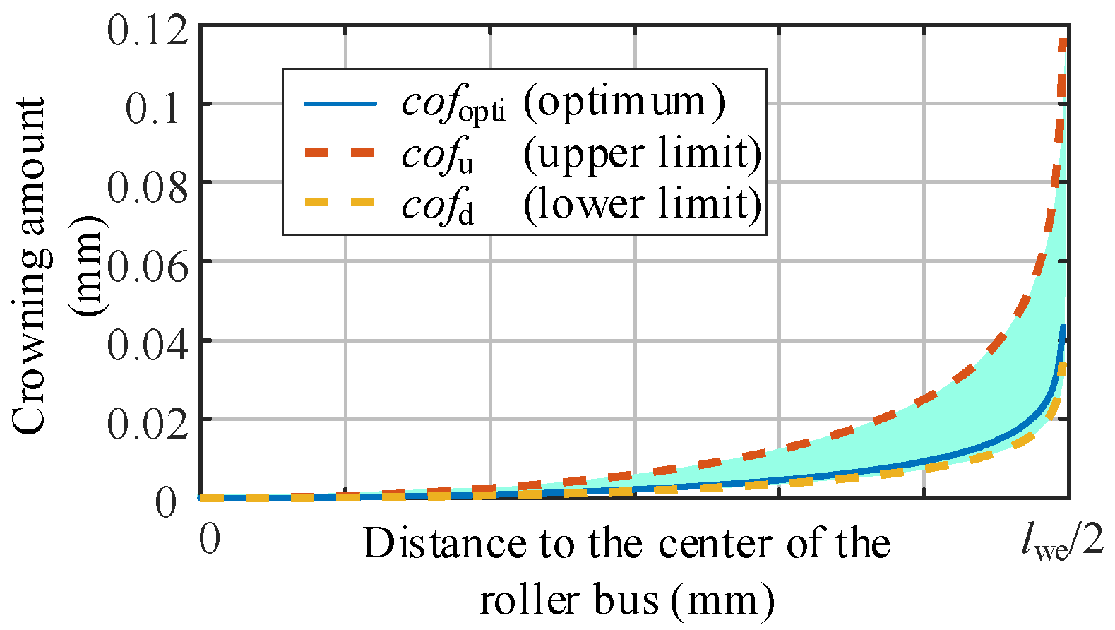
- The sub-model of the upwind bearing is constructed with structured mesh. With the crowning parameters of the logarithmically crowned roller as the design variables and the maximum Von Mises stress of the roller profile at the center of the contact area as the design target, the optimal logarithmic crowning of the roller and its tolerance zone under the given working conditions are obtained.
Author Contributions
Funding
Data Availability Statement
Conflicts of Interest
References
- Doll, M.N.K.; Gary, L. Tribological advancements for reliable wind turbine performance. Philos. Trans. 2010, 368, 4829–4850. [Google Scholar]
- Hart, E.; Clarke, B.; Nicholas, G.; Amiri, A.K.; Stirling, J.; Carroll, J.; Dwyer-Joyce, R.; McDonald, A.; Long, H. A review of wind turbine main bearings: Design, operation, modelling, damage mechanisms and fault detection. Wind. Energy Sci. 2020, 5, 105–124. [Google Scholar] [CrossRef] [Green Version]
- Smolnicki, T.; Rusiński, E. Superelement-based modeling of load distribution in large-size slewing bearings. J. Mech. Des. 2007, 129, 459–463. [Google Scholar] [CrossRef]
- Chen, G.; Wang, C.; Xiao, Z. Effects of supporting structure and bolt connection on the fatigue life and carrying capacity of a slewing bearing. J. Eng. Tribol. 2016, 231, 766–782. [Google Scholar] [CrossRef]
- Chen, G.; Wen, J. Load Performance of Large-Scale Rolling Bearings With Supporting Structure in Wind Turbines. J. Tribol. 2012, 134, 041105. [Google Scholar] [CrossRef]
- Plaza, J.; Abasolo, M.; Coria, I.; Aguirrebeitia, J.; Igor, F.B. A new finite element approach for the analysis of slewing bearings in wind turbine generators using superelement techniques. Meccanica 2015, 50, 1623–1633. [Google Scholar] [CrossRef]
- Li, Y.; Jiang, D.; Song, L. Finite Element Analysis of Pitch Bearing in Wind Turbine Considering Influence of Installation Structures. Acta Energ. Sol. Sin. 2019, 40, 2021–2027. (In Chinese) [Google Scholar]
- Aguirrebeitia, J.; Abasolo, M.; Avilés, R.; Igor, F.B. General static load-carrying capacity for the design and selection of four contact point slewing bearings: Finite element calculations and theoretical model validation. Finite Elem. Anal. Des. 2012, 55, 23–30. [Google Scholar] [CrossRef]
- He, P.; Liu, R.; Hong, R.; Wang, H.; Yang, G.; Lu, C. Hardened raceway calculation analysis of a three-row roller slewing bearing. Int. J. Mech. Sci. 2018, 137, 133–144. [Google Scholar] [CrossRef]
- Śpiewak, S. Methodology for calculating the complete static carrying capacity of twin slewing bearing. Mech. Mach. 2016, 101, 181–194. [Google Scholar] [CrossRef]
- Martín, I.; Aguirrebeitia, J.; Heras, I.; Abasolo, M. Efficient Finite Element modelling of crossed roller wire race slewing bearings. Tribol. Int. 2021, 161, 107098. [Google Scholar] [CrossRef]
- Kania, L.; Pytlarz, R.; Śpiewak, S. Modification of the raceway profile of a single-row ball slewing bearing. Mech. Mach. Theory 2018, 128, 1–15. [Google Scholar] [CrossRef]
- Ju, S.H.; Horng, T.L.; Cha, K.C. Comparisons of contact pressures of crowned rollers. J. Eng. Tribol. 2000, 214, 147–156. [Google Scholar] [CrossRef]
- Fujiwara, H. Logarithmic profile of rollers in roller bearing and optimization of the profile. Trans. Jpn. Soc. Mech. Eng. 2006, 72, 338–345. (In Japanese) [Google Scholar] [CrossRef] [Green Version]
- He, Z.; Shao, M.; Ye, G. Optimum Design Method for Logarithmic Crowned Tapered Rollers. Mech. Eng. Technol. 2016, 5, 38–46. [Google Scholar] [CrossRef]
- Li, Y.; Gao, Y. Internal load distribution of single-row tapered roller bearings doubly supporting main shaft of wind turbine. Adv. Mech. Eng. 2022, 14, 16878132221098895. [Google Scholar] [CrossRef]
- Zhang, T.; Yang, X.; He, L.; Bu, Z.J.; Nie, W.; Li, M. Research on the Design Method of Roller Modification Curve for Wind Turbine. J. Mech. Strength 2021, 43, 183–190. (In Chinese) [Google Scholar]
- Li, Y.; Xu, Z.; Liu, Q.; Wang, H. Analysis on Contact Behavior for Extra Large Size Tapered Roller Bearings in Wind Turbines Based on PERMAS. Bearing 2014, 5, 1–4. (In Chinese) [Google Scholar]
- Liu, J.; Dong, H.; Wang, H.; Wang, Y.Y. Finite Element Analysis of Slewing Bearing Based on Rolling Element Solid Model and Substructure Technology. Bearing 2018, 12, 9–13. (In Chinese) [Google Scholar]
- Kania, L. Modelling of rollers in slewing bearing calculations with the use of finite elements. Mech. Mach. Theory 2006, 41, 1359–1376. [Google Scholar] [CrossRef]
- Harris, T.A.; Kotzalas, M.N. Advanced Concepts of Bearing Technology: Rolling Bearing Analysis, 5th ed.; CRC Press: Boca Raton, FL, USA, 2006; pp. 3–7. [Google Scholar]
- Palmgren, A. Ball and Roller Bearing Engineering, 3rd ed.; SKF Industries Inc.: Philadelphia, PA, USA, 1959. [Google Scholar]
- Wang, P.; Wang, Q.; Xu, X.; Chen, N. Fractional Critical Damping Theory and Its Application in Active Suspension Control. Shock. Vib. 2017, 2017, 2738976. [Google Scholar] [CrossRef]
- Zeng, P.; Lei, L.; Fang, G. Finite Element Analysis Guide: Modeling and Analysis of Structure; China Machine Press: Beijing, China, 2011; pp. 428–430. [Google Scholar]
- Lundberg, G.; Palmgren, A. Dynamics capacity of rolling bearings. Acta Polytech. 1947, 1, 7. [Google Scholar] [CrossRef]
- Zhang, H.; Chen, S.; Dou, Y.; Fan, H.; Wang, Y. Mechanical model and contact properties of double row slewing ball bearing for wind turbine. Rev. Adv. Mater. Sci. 2021, 60, 112–126. [Google Scholar] [CrossRef]
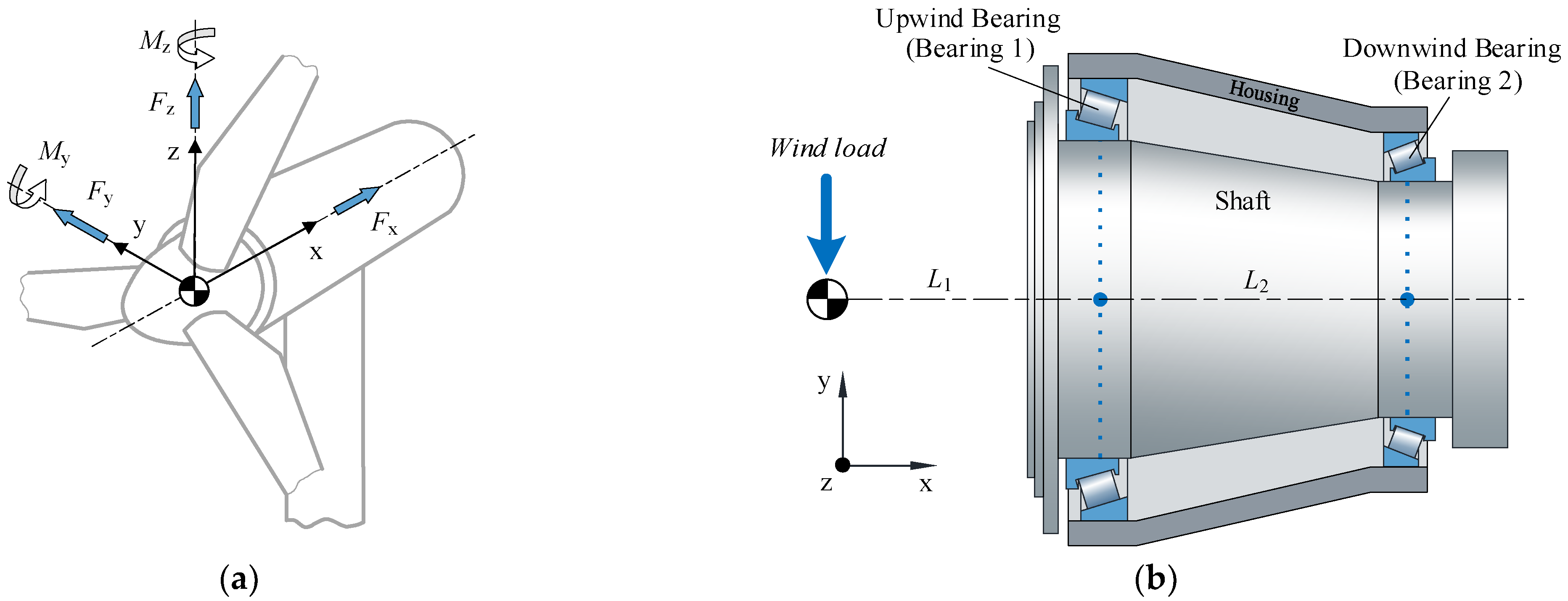






| Parameter | Value | |
|---|---|---|
| Bearing 1 | Bearing 2 | |
| Inner diameter d (mm) | 1850 | 1600 |
| Number of rollers Z | 62 | 65 |
| The contact angle of inner raceway αi (°) | 15.58 | 19.5 |
| The contact angle of outer raceway αe (°) | 17.1 | 21.17 |
| The contact angle of roller end–ring flange αf (°) | 83.52 | 69.67 |
| Length of rollers l (mm) | 121 | 98 |
| Roller diameter in the middle Dw (mm) | 95.085 | 73.26 |
| Roller half taper angle β (°) | 0.75 | 0.833 |
| pitch diameter dm (mm) | 2043 | 1750 |
| Fx/N | Fy/N | Fz/N | My/Nm | Mz/Nm |
|---|---|---|---|---|
| 7.5 × 10⁵ | 1.1 × 10⁶ | 3 × 10⁴ | 1700 | −2700 |
| FEM with Flexible Structure/N | FEM with Rigid Structure/N | Theory Based on Rigid Ring Assumption/N |
|---|---|---|
| 122,731.03 | 125,830.48 | 145,680 |
| (−15.75%) | (−13.63%) | (—) |
Disclaimer/Publisher’s Note: The statements, opinions and data contained in all publications are solely those of the individual author(s) and contributor(s) and not of MDPI and/or the editor(s). MDPI and/or the editor(s) disclaim responsibility for any injury to people or property resulting from any ideas, methods, instructions or products referred to in the content. |
© 2022 by the authors. Licensee MDPI, Basel, Switzerland. This article is an open access article distributed under the terms and conditions of the Creative Commons Attribution (CC BY) license (https://creativecommons.org/licenses/by/4.0/).
Share and Cite
Liu, X.; Niu, R.; Wang, B.; Zhang, S.; Cui, Y.; Zhang, Z. Crowning Method on Bearing Supporting Large Wind Turbine Spindle Considering the Flexibility of Structure of Shaft System. Machines 2023, 11, 28. https://doi.org/10.3390/machines11010028
Liu X, Niu R, Wang B, Zhang S, Cui Y, Zhang Z. Crowning Method on Bearing Supporting Large Wind Turbine Spindle Considering the Flexibility of Structure of Shaft System. Machines. 2023; 11(1):28. https://doi.org/10.3390/machines11010028
Chicago/Turabian StyleLiu, Xiangyang, Rongjun Niu, Bin Wang, Shuai Zhang, Yongcun Cui, and Zhanli Zhang. 2023. "Crowning Method on Bearing Supporting Large Wind Turbine Spindle Considering the Flexibility of Structure of Shaft System" Machines 11, no. 1: 28. https://doi.org/10.3390/machines11010028
APA StyleLiu, X., Niu, R., Wang, B., Zhang, S., Cui, Y., & Zhang, Z. (2023). Crowning Method on Bearing Supporting Large Wind Turbine Spindle Considering the Flexibility of Structure of Shaft System. Machines, 11(1), 28. https://doi.org/10.3390/machines11010028


