1. Introduction
Magnetorheological fluid is a new type of intelligent fluid. The most important and obvious feature of MRF (magnetorheological fluid) is their reversible transition from liquid to semi-solid state in milliseconds owing to the influence of magnetic fields, and vice versa. This change in the state and properties is referred to as the magnetorheological effect [
1,
2]. The damping characteristics of the MRF steadily vary with the external magnetic field, which makes it an excellent working fluid for mechanical damping and isolation devices [
3]. Shock absorbers with MRF as the working fluid have the advantages of low energy consumption, fast response, simple structure, adjustable damping force [
4,
5,
6,
7], and a wide range of applications in the automotive industry [
8,
9,
10].
Magnetorheological mounts have been extensively studied for many years. Bai et al. and Lin et al. derived pseudohomeostatic mathematical models of MRF for the theoretical analysis of the dynamic stiffness and equivalent damping characteristics of MRF mounts [
11,
12]. Most optimization studies have been conducted using similar models. Aiming at the problem of automatic starting/stopping of the engine, which leads to driver discomfort, Chung et al. designed and optimized a magnetorheological mount with a large damping force and force ratio [
13]. Certain results have been obtained in engineering applications. Zheng et al. established a lumped parameter model of an MR (magnetorheological) engine mount in a single-degree-of-freedom system and carried out a multi-objective optimization design [
14]. It has a certain reference value for optimization and provides a relatively standard optimization method for future research. Deng et al. conducted various studies on magnetorheological mount optimization. A magnetorheological mount for controlling the vibration and torque excitation of the engine when the vehicle is in start–stop mode was proposed, and the dynamic performance test of the magnetorheological mount unit and the vibration isolation performance test of the entire vehicle in the start–stop mode were verified [
15]. To improve the quality of vehicle NVH (Noise, Vibration, Harshness), an optimization study was conducted using Isigt, MATLAB, and ANSYS software to develop an optimal co-simulation platform [
16]. Aiming at the problem of premature saturation of the magnetic induction intensity when the inner diameter of the core is large, a tapered channel is proposed, and the magnetic circuit is optimized [
17]. A multi-objective optimization scheme for an MR damper based on the vehicle dynamics model was proposed by introducing the damping force into the vehicle dynamics model [
18]. After years of research, Deng et al. have made breakthroughs and advances in the field of magnetorheological mount optimization. However, there are still some situations, such as the difference between the theoretical derivation model used and the actual working conditions at different frequencies, that have not been taken into account.
MRF mounts have many similarities with MRF dampers, and many studies can also be used as references. Considering the improvement in the performance of MRF dampers, many methods have been proposed to improve the internal structure of the MRF dampers [
19,
20,
21]. The performance of an MRF damper heavily depends on activating the magnetic circuit; therefore, the performance of an MR damper can be optimized by activating the design of the magnetic circuit [
22]. Parlak et al. conducted a multi-objective optimization study with the damping force and maximum magnetic flux density as the optimization goals [
23], wherein the maximum dynamic range and maximum damping force were used as the optimization goals [
24]. Jiang et al. optimized the structure of an MRF damper using the NSGA-II algorithm based on the maximum dynamic range and minimum number of turns of the electromagnetic coil [
25]. Hu et al. studied the effect of different piston shapes on the MRF damper performance using finite element analysis [
26]. Ferdaus et al. conducted finite element analysis to study the performance variation of dampers in different configurations [
27]. Dong et al. studied the function of the damping force, dynamic range, response time, and damping gap magnetic flux density consistency as the optimization goal [
28]. Scholars at home and abroad have conducted considerable research on the optimal design of MRF dampers and proposed a variety of different ideas and optimization algorithms; optimized design and experimental design based on parameter programming are the two methods commonly used at present.
Most studies have not considered the difference between the theoretical models and actual work on mounts. Particularly, the theoretical model of the fluid is significantly different from the actual magnetorheological suspension at different frequencies, and the performance of the MR fluid cannot be exerted with an increase in frequency. Using the method presented in this paper, resilience at different frequencies can be estimated from the experimental data. The accuracy of the model can be further improved by comparing its reliability. Owing to the research time, the refined optimization of the proposed model is still at a relatively basic stage; however, it still provides some ideas and has a certain reference value for subsequent research.
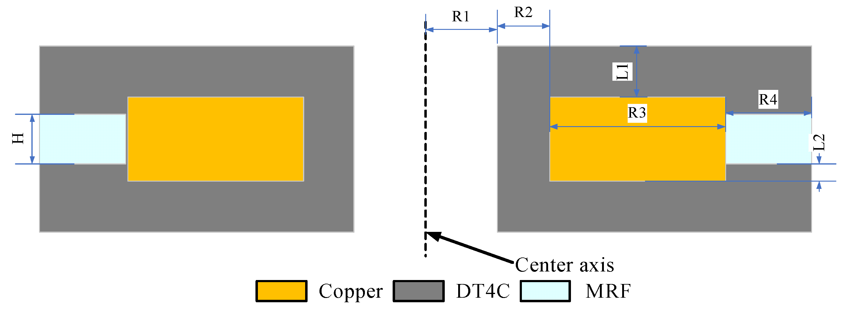
In this study, an MRF mount with a toroidal radial channel was designed, which can have a large damping force and controllable range, even under certain geometric dimensional constraints [
29]. To be more in line with engineering practice and practical application scenarios, under the premise of ensuring accuracy, the magnetic circuit model was simplified as much as possible, and the calculation speed was improved. Considering the engine vibration isolation to be the most important function, the damping force size and controllable range are set as the optimization goals, the best optimization effect is expected, and the optimal solution of the MRF mount is obtained in combination with finite element analysis and optimization design tools.
3. Analysis of Sensitivity
To explore the sensitivity of each structural parameter to the damping force, Isight software and Maxwell were used to jointly simulate the sensitivity analysis under 10 Hz of the common working conditions of the magnetorheological mount. Taking the size of the suspended magnetic circuit structure as the design variable, the number of design variables is 7, and the viscous damping force and coulomb damping force of the mount are selected as the responses. Owing to the advantages of the effective spatial filling ability of the Latin hypercube and the fitting nonlinear response, the Latin hypercube sampling method was selected in this study.
The selection of the value range includes the maximum number of possible size parameters that fits the space size limit of this mount.
Table 2 shows the selected optimization design variables and their respective value ranges.
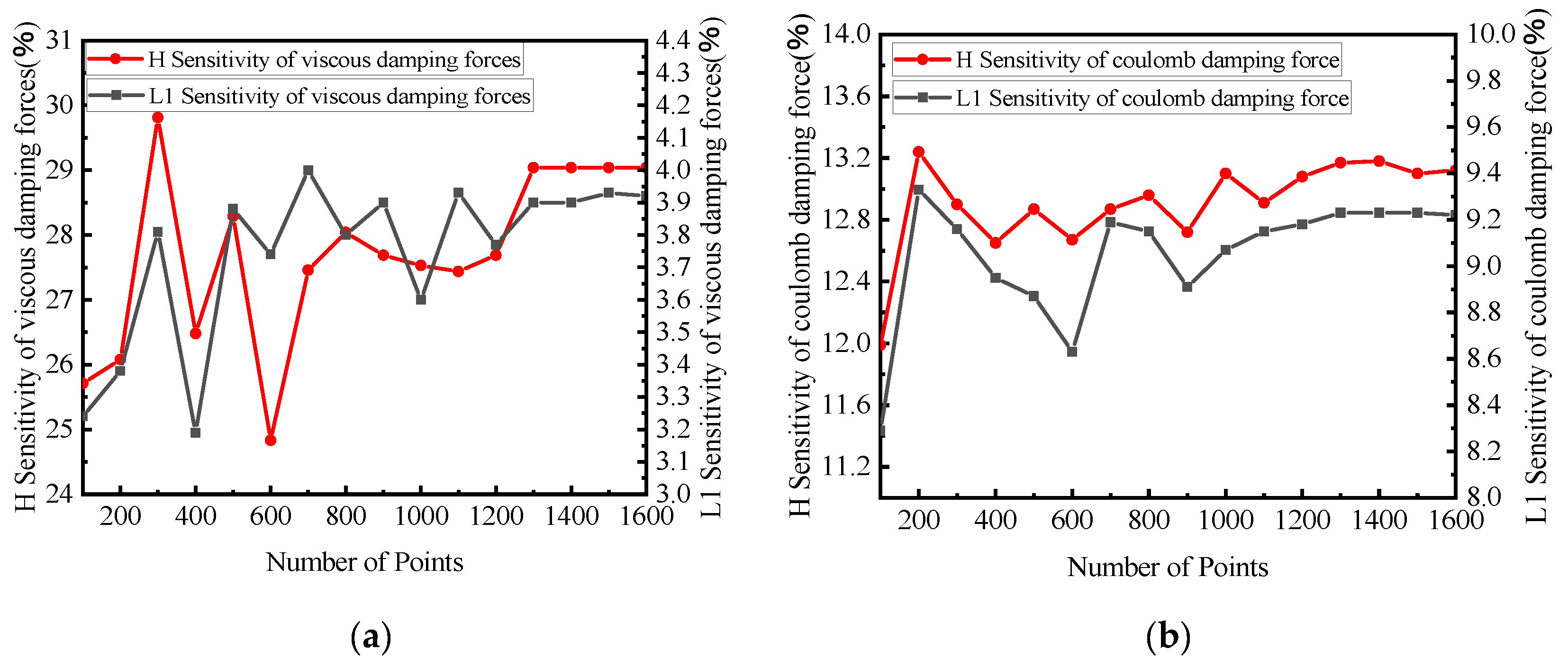
To determine the most appropriate number of the sampling points, different sampling points were selected for the analysis and their influence on the simulation was studied. The simulation results are shown in
Figure 17, where the red curve represents a negative effect. With the change of the number of sampling points, the influence of each structural parameter on the damping force fluctuates within a certain range, the influence of each structural parameter on the viscous damping force from the number of sampling points starts at 1400, and the fluctuation amplitude of each structural parameter on the viscous damping force is less than 0.5%; therefore, it is considered that it tends to converge, and the number of sampling points is selected to be 1400.
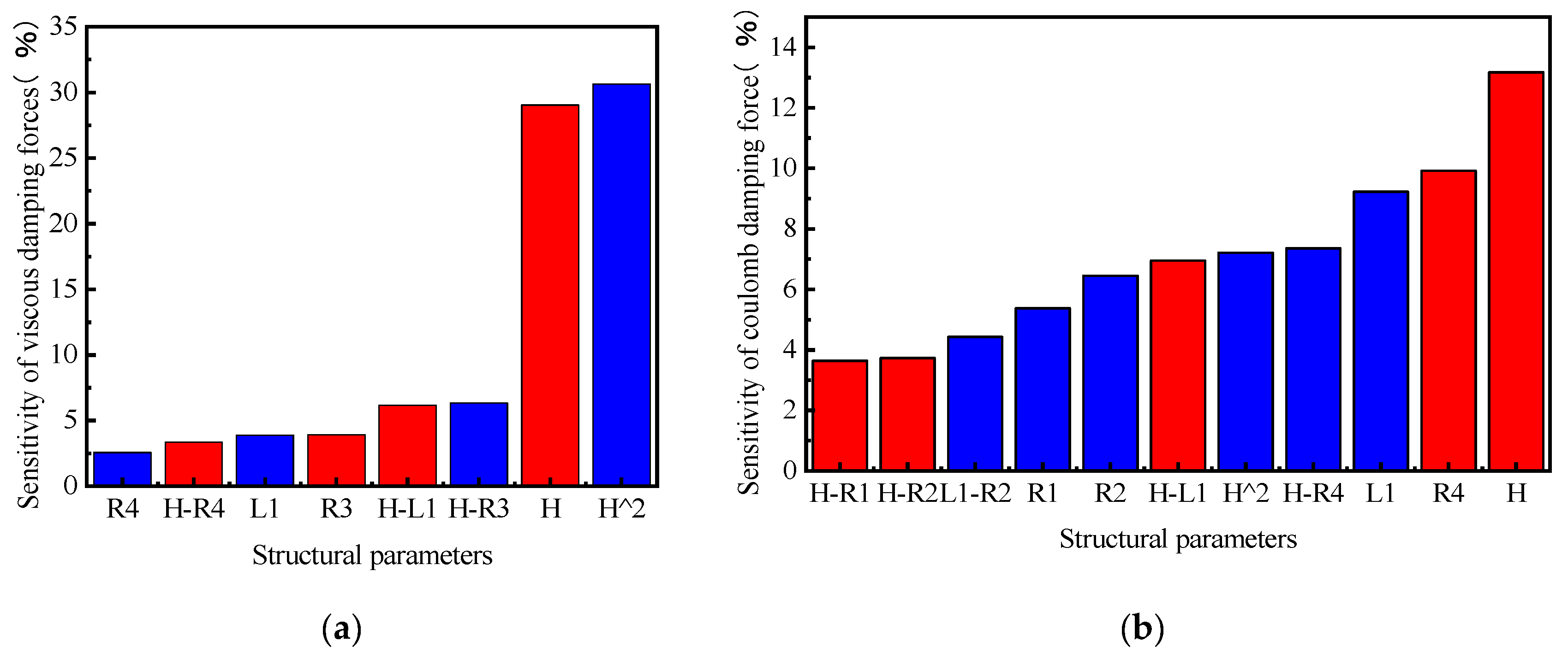
Figure 18 shows the sensitivity of each structural parameter to damping force. Because of the excessive data of each structure, if all the data are plotted in the figure, it will affect the display effect.
Figure 18a below only shows the data with a sensitivity of more than 2.5%, and
Figure 18b shows that the data are denser and only shows a sensitivity of more than 3.5% (blue represents positive effects, and red represents negative effects).
Combined with the above sensitivity analysis results, among the seven structural parameters, L2 had the least sensitive effect on the damping force. The dimensions that determine the cross-sectional area of the inertial channel, namely, H and R4, were the most sensitive. Combined with the theoretical derivation formula, R4 and H are directly related to the cross-sectional area of the inertial channel. R2 and L1 are directly related to the coil, and the sizes of the four parameters R1, R2, R3, and R4 determine the length of the inertial channel. The output damping force of the MRF mount is related to the structural parameters of the magnetic circuit and the magnetic induction strength of the MRF in the effective damping channel. The viscous damping force of the mount is determined only by the parameters of the magnetic circuit structure, whereas the coulomb damping force is determined by the structural parameters of the magnetic circuit and the magnetic induction strength of the MRF in the effective damping channel. Both the simulation results and theories show that L2 has little effect on the viscous and coulomb damping forces. In the results that are not shown here, the sensitivity of the viscous damping force with L2 was up to 0.84%, and the sensitivity of the coulomb damping force with L2 was up to 1.09%. The effect of L2 on the damping force was negligible, that is, less than 4%.
4. Multi-Objective Optimization Design of Magnetic Circuits
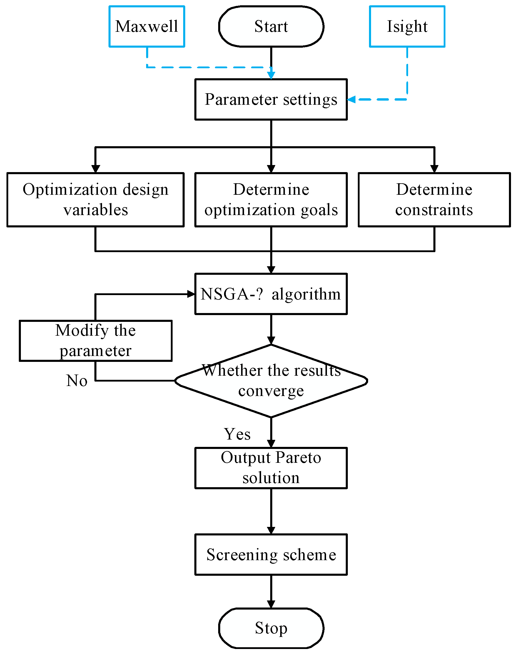
The optimization design, which is presented using Maxwell and Isight for the co-simulation, is shown in
Figure 19. The determination of the three optimization elements of the optimization objectives, design variables, and constraints is extremely important for optimization. Additionally, the main parameters of the algorithm are changed to achieve convergence. The Pareto frontier is analyzed, and the optimal individuals that best meet the requirements are selected through fuzzy set theory and experience.
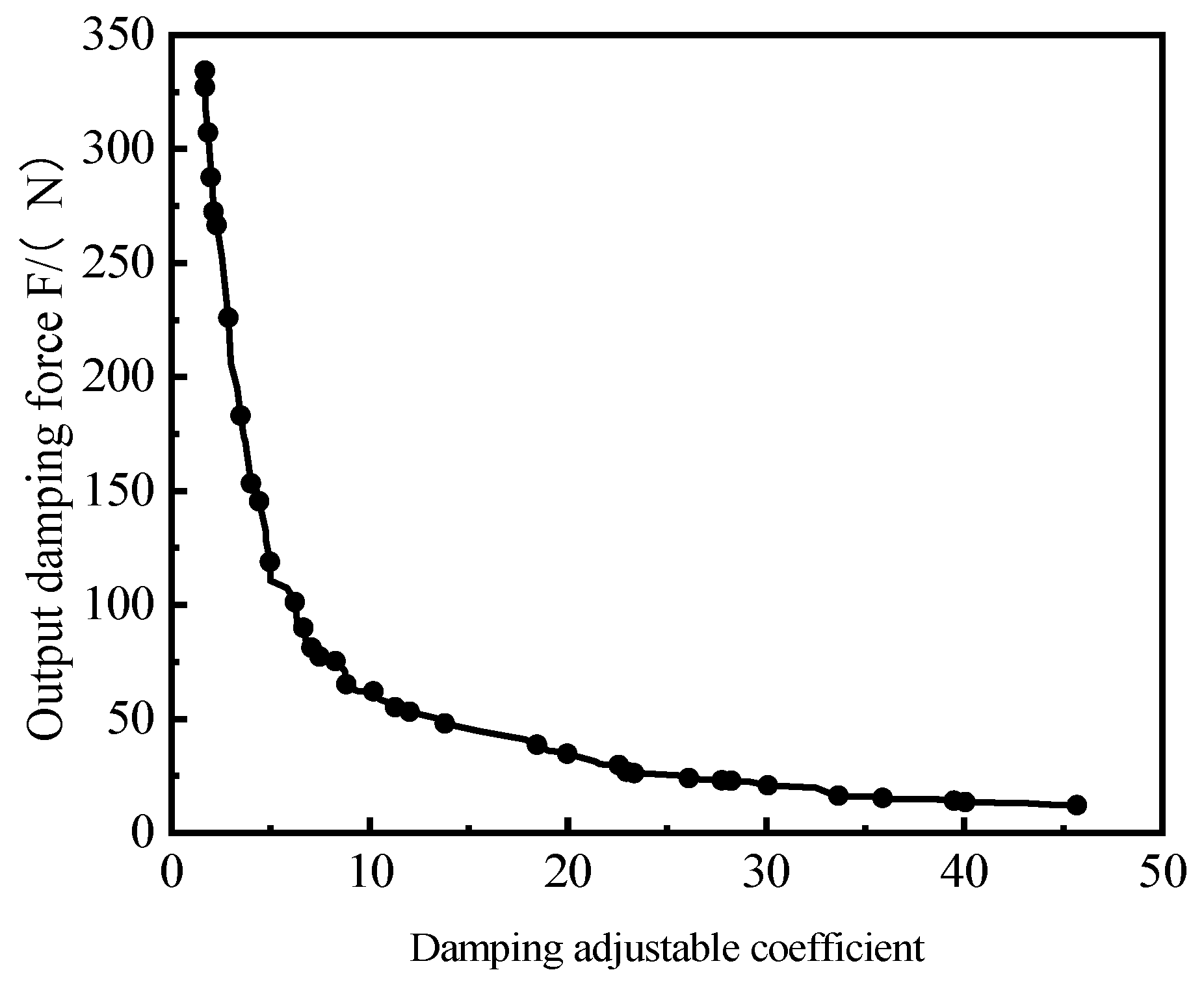
The vibration isolation performance of the mount is determined by the viscous damping force and coulomb damping force. The greater the output damping force, the stronger is the absorption effect on the vibration. The adjustable damping coefficient reflects the ability of the MRF mount to adjust the damping force range; furthermore, the larger the adjustable damping coefficient, the wider the working conditions are for which the damper can be applied. Therefore, the maximum output damping force and damping adjustable coefficient are the optimization goals.
The damping adjustability factor is defined to evaluate the adjustability of the mount:
The objective function can be expressed as:
The structural parameters of the sensitivity analysis were selected as design variables after comprehensive consideration of the magnetic circuit design requirements, working characteristics, and mechanical characteristics of the MRF mount. Simultaneously, combined with the sensitivity analysis results, the design variables are set as
H,
L1,
R1,
R2,
R3 and
R4, which are six structural parameters, as listed in
Table 3.
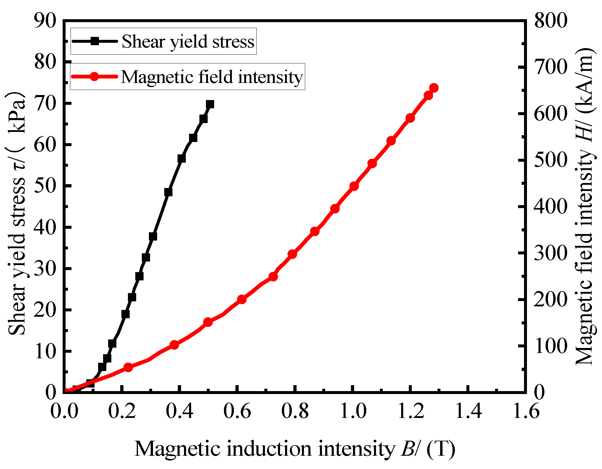
Combined with the dimensional design requirements of this mount and the actual material characteristics, the magnetic induction strength of the design should be less than the saturated magnetic induction strength of the MRF and DT-4C. The constraint formula is as follows:
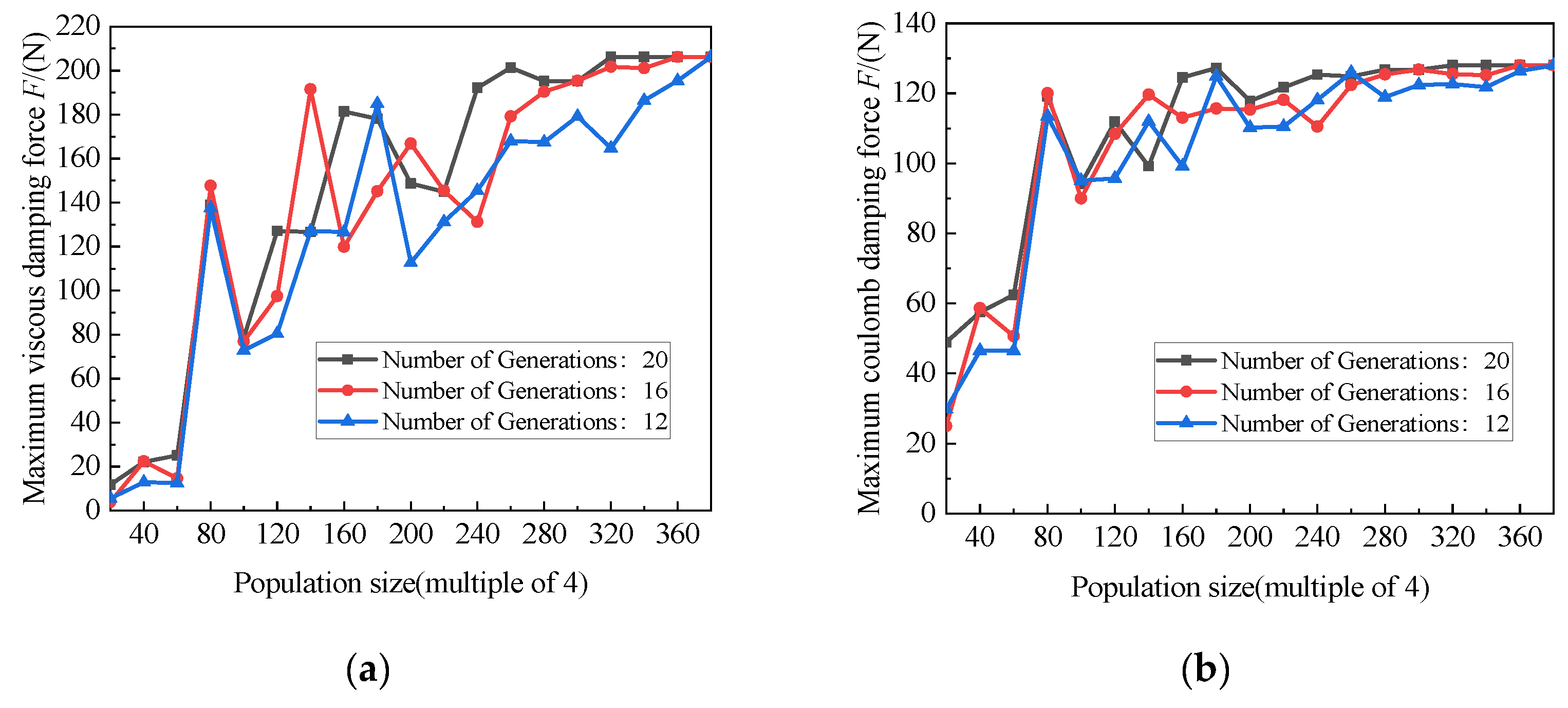
The NSGAII algorithm has the advantage of a good exploration performance. To obtain the global optimal value, the NSGA II algorithm was used to perform global search optimization on the entire design space of the optimized variables [
35]. The crossover rate, crossover distribution index, and mutation distribution index were set to 0.9, 10, and 20, respectively [
36]. As shown in
Figure 20, with an increase in the population size and maximum evolutionary algebra, the optimized maximum viscous damping force and coulomb damping force gradually begin to converge, and the subsequent fluctuation range is less than 5 N, which is considered to have converged. Therefore, the population size and maximum evolutionary algebra were selected to be 320 and 20, respectively.
After calculation, 101 Pareto optimal solutions for the suspended magnetic circuit were obtained; the Pareto front is shown in
Figure 21. Obviously, the inverse relationship between the two objective functions of the output damping force and damping tunable coefficient is not guaranteed to simultaneously meet the maximum design goal. Therefore, it is particularly important to select the individual in the Pareto noninferior solution as the optimal individual.
Table 4 lists the partial solutions for Pareto’s optimal solution set domain.
To better solve the multi-objective optimization problem, fuzzy set theory was used to perform further selection among the solution sets. The membership function
and domination function
are defined as follows:
where
and
are the maximum and minimum values of the
optimization target, respectively;
is the value of the
optimization goal;
is the number of solutions contained in the Pareto set; and
is the number of optimization targets.
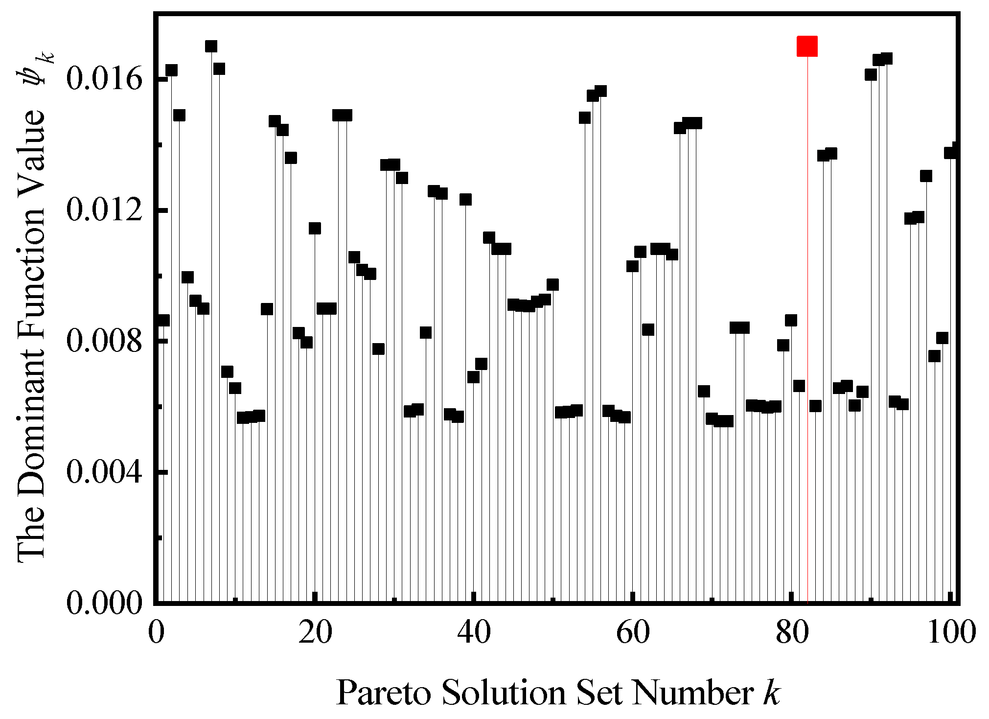
We calculated the domination function of each individual in the Pareto optimal solution set; the larger the
, the better is the overall performance of the solution. As shown in
Figure 22, the dominance value of individual No. 82, with the largest dominant function value, was approximately 0.0170. Individuals 7, 91, and 92 were similar to their dominant values, and individual 7 was excluded due to small damping forces. Individuals 91 and 92 were similar in size, which is limited by the manufacturing process in the actual manufacturing and can be regarded as a result. Compared to individual No. 82, the average magnetic induction intensity of individual No. 82 at 1.5 A current is approximately 0.512 T, whereas No. 91 and No. 92 are only 0.487 T, which is obviously higher than the magnetic induction intensity of individual No. 82, which is regarded as the optimal individual that best meets the requirements.
5. Comparison of Results
Table 5 shows the magnetic circuit structure before and after the multi-objective optimization. Owing to the limitations of the actual manufacturing process, the optimization results are only taken to one decimal place.
Table 6 compares the results when the excitation current was 1.5 A before and after optimization. After optimization, the theoretical output damping force of the MRF mount was 336.19 N, which was 44.64% higher than that before optimization. The controllable force and zero magnetic field damping force were also increased by 43.70% and 47.64%, respectively, and the adjustable damping coefficient was reduced by −2.50%. The description shows that the optimization method has an obvious effect on improving the damping performance of the mount and ensures that the MRF mount has a wider adjustable ability. The adjustable damping coefficient is reduced, which also reflects the inverse trend of the two optimization goals from the side, which is consistent with the above analysis of the optimization solution set.
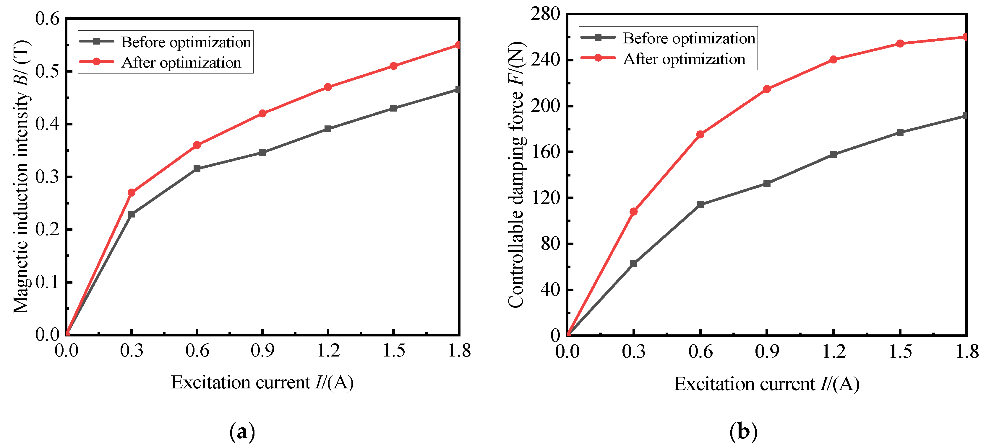
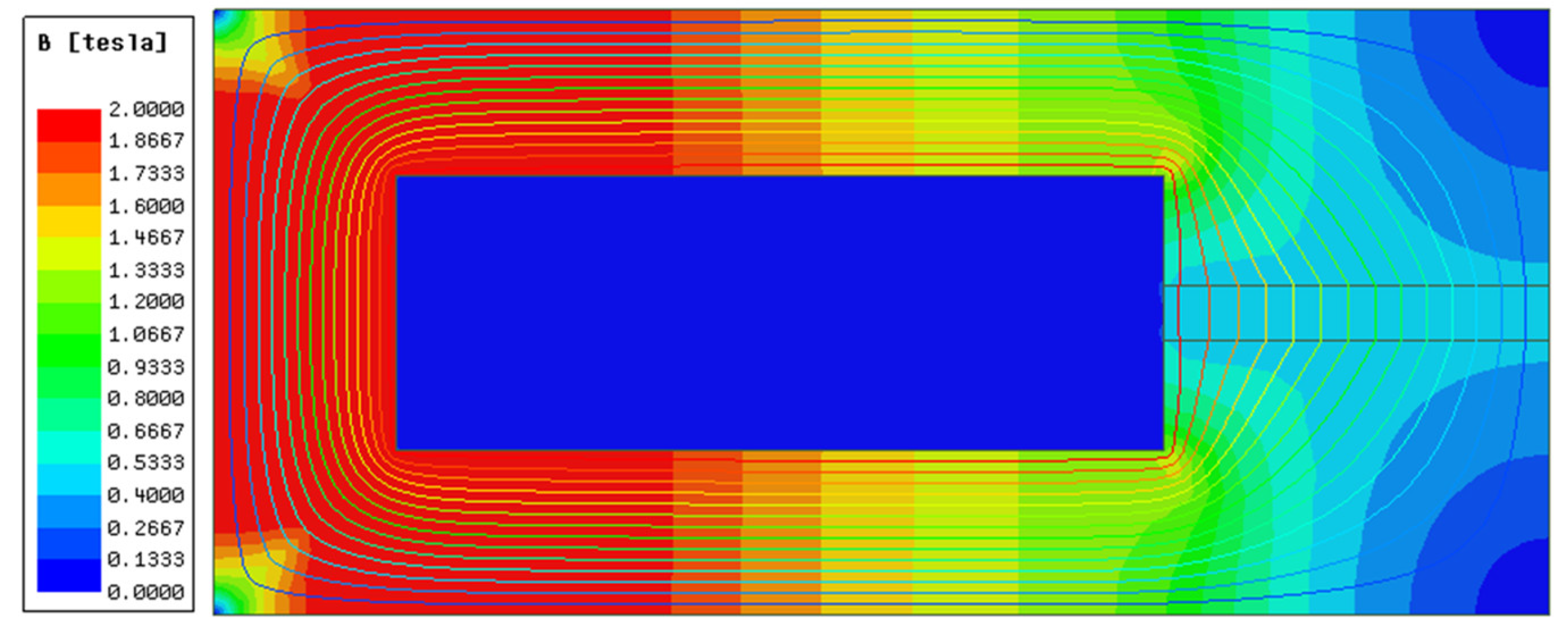
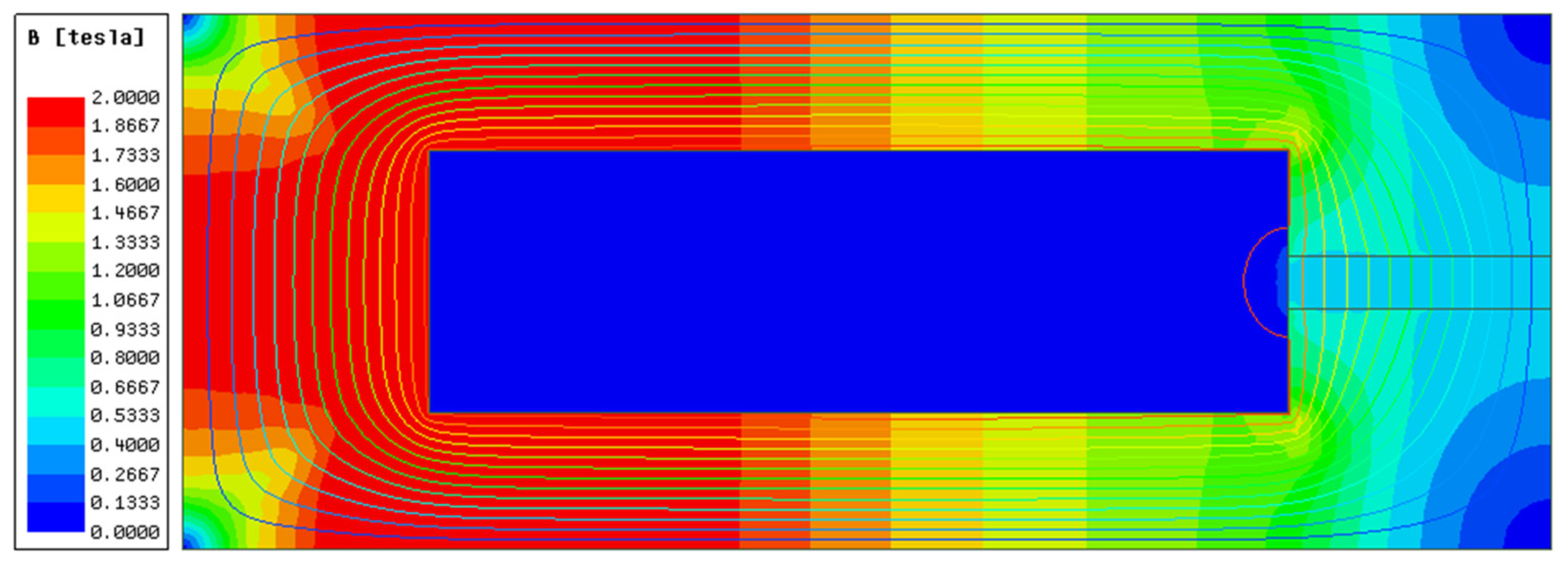
As shown in
Figure 23, when the excitation current is the maximum working current, that is, I = 1.5 A, the magnetic induction intensity at the channel corresponding to the effective magnetic pole varies relatively evenly with the radial distance, and the average magnetic induction intensity is approximately 0.51 T. The MRF was close to saturation and significantly higher than that before optimization.
Figure 24 shows a comparison between before and after the optimization. After optimization, the magnetic induction intensity increased significantly under the same current. The average magnetic induction intensity at the optimized damping channel is approximately 0.43 T at 1.5 A, the average magnetic induction intensity at the optimized damping channel is approximately 0.51 T, and the average magnetic induction intensity is increased by 18.60%. The enhancement of the magnetic induction strength indicates that the utilization rate of the magnetic circuit is improved, effectively reducing energy consumption. The controllable force increases with an increase in current, and the controllable force is greater after optimization. The controllable force increases from 1.5 A to 1.8 A before optimization by 8.20%, and only by 2.26% after optimization. This indicates that the damping performance is maximized when the optimized mount is 1.5 A, which meets the design requirements.


 ,
, 


