Article

A Knowledge Graph-Based Approach for Assembly Sequence Recommendations for Wind Turbines

1
College of Mechanical Engineering, Donghua University, Shanghai 201620, China
2
School of Mechanical Engineering, University of Shanghai Science and Technology, Shanghai 200093, China
*
Author to whom correspondence should be addressed.
Machines 2023, 11(10), 930; https://doi.org/10.3390/machines11100930
Submission received: 6 August 2023 / Revised: 20 September 2023 / Accepted: 24 September 2023 / Published: 27 September 2023
(This article belongs to the Special Issue Smart Processes for Machines, Maintenance and Manufacturing Processes)

Abstract

:
There are various forms of assembly data sources for wind turbines, which contributes to the lack of a unified and standardized expression. Moreover, the reusability of historical assembly data is low, which leads to the poor reasoning ability of a new product assembly sequence. In this paper, we propose a knowledge graph-based approach for assembly sequence recommendations for wind turbines. First, for the multimodal data (text in process manual, image of tooling, and three-dimensional (3D) model) of assembly, a multi-process assembly information representation model is established to express assembly elements in a unified way. In addition, knowledge extraction methods for different modal data are designed to construct a multimodal knowledge graph for wind turbine assembly. Further, the retrieval of similar assembly process items based on the bidirectional encoder representation from transformers joint graph-matching network (BERT-GMN) is proposed to predict the assembly sequence subgraphs. Also, a Semantic Web Rule Language (SWRL)-based assembly process items inference method is proposed to automatically generate subassembly sequences by combining component assembly relationships. Then, a multi-objective sequence optimization algorithm for the final assembly is designed to output the optimal assembly sequences. Finally, taking the VEU-15 wind turbine as the object, the effectiveness of the assembly process information modeling and part multi-source information representation is verified. Sequence recommendation results are better quality compared to traditional assembly sequence planning algorithms. It provides a feasible solution for wind turbine assembly to be optimized from multiple objectives simultaneously.

1. Introduction

With the rapid development of intelligent advanced technologies such as big data and artificial intelligence, traditional manufacturing is gradually transforming into intelligent manufacturing [1,2]. The concept of Industry 4.0 provides an opportunity for manufacturing enterprises to integrate data at all stages of the product life cycle, so as to better meet the needs of users’ personalized and customized products [3]. As a customized electromechanical product, the manufacturing process of large wind turbines can be divided into three major parts, including manufacturing process, logistics process, and on-site process. Among them, assembly as the core link of the on-site process is the last step of wind turbine installation. The assembly quality directly affects the reliability and working performance of the wind turbine. In addition, the assembly workload of each component has always occupied a high ratio of the development workload of the whole product. The assembly time accounts for more than 40% of the manufacturing time of the whole wind turbine [4]. The development of artificial intelligence provides opportunities for assembly semantic processing and assembly sequence recommendations, which focus on analyzing and planning assembly sequences more effectively [5,6].
Assembly knowledge is constantly evolving in practice, providing a key reference for the design and manufacturing of complex products [7,8,9]. Manufacturing products are constantly iterated and upgraded. Thus, a large amount of historical data is generated. However, the lack of effective organization of these heterogeneous data makes it difficult to provide technicians with convenient knowledge services. Therefore, the search for efficient data organization and convenient knowledge acquisition methods has become an urgent problem for a long time. In addition, in traditional assembly sequence planning, the selection of assembly solutions based on different assembly requirements is often realized semi-automatically by assembly personnel based on manual experience or computer-aided tools. How to obtain the assembly object, assembly process, and other related information based on the existing assembly knowledge with a sequence planning solution is also a major difficulty in current intelligent planning.
Researchers have applied knowledge graphs to build structured semantic networks in manufacturing, especially in assembly, and have demonstrated its application value in guiding assembly work in real industrial scenarios [10,11,12]. This is because knowledge graphs can describe assembly objective concepts and their interrelationships in a structured form [13], where the subordination between assembly entities and assembly attributes can be visually expressed. It provides powerful support for the sharing, querying, and derivation of assembly knowledge.
However, since the planning of assembly sequences for complex wind turbine products is a combinatorial optimization problem, the results generated by the sequence may be unreasonable. In addition, the actual assembly process is also limited by factors such as assembly stability and assembly reorientation. Therefore, the sequences obtained by traditional manual experience and similarity matching methods are usually not the optimal solutions. It is necessary to combine the wind turbine-specific assembly requirements and the optimization degree of several assembly evaluation indexes to obtain the optimal or near-optimal feasible assembly sequences.
Based on the problems emphasized above, in this paper, a knowledge graph-based approach for assembly sequence recommendations for wind turbines is proposed. Firstly, the assembly information representation model is developed to link knowledge from the assembly process text, on-site installation images, and 3D part models. Also, knowledge extraction methods for different modal data are designed to construct a knowledge graph for wind turbine assembly. Then, a graph-matching network (GMN) is designed for the retrieval of similar assembly process items. Further, the Semantic Web Rule Language (SWRL) is used for assembly semantic rule reasoning to mine the implicit relationships between total assemblies and parts. Then, a multi-objective sequence optimization algorithm for the final assembly is designed to output the optimal assembly sequences. Finally, the VEU-15 wind turbine generator is used as a case object to demonstrate the effectiveness of the proposed method for the recommended design of assembly sequences with multi-configuration requirements.
The innovations of this paper are as follows:
(1)
The assembly information representation model is designed to describe the assembly information data from multiple sources in a unified way. Then, multiple modal assembly entity joint extraction methods are proposed to construct a multimodal knowledge graph for wind turbine assembly.
(2)
A knowledge graph-based optimal assembly sequence recommendation is proposed. The retrieval of similar assembly process items based on BERT-GMN is proposed to predict the assembly sequence subgraphs. Also, a SWRL-based assembly process item inference method is proposed to automatically generate subassembly sequences by combining component assembly relationships. Then, a multi-objective sequence optimization algorithm for the final assembly is designed to output the optimal assembly sequences.
The rest of this paper is organized as follows: Section 2 introduces the literature review of assembly domain knowledge graph construction and assembly sequence planning. Section 3 proposes the knowledge graph-based assembly sequence recommendations for wind turbines in detail. In Section 4, the VEU-15 wind turbine generator is taken as an example to verify the effectiveness of the proposed method in this paper. Finally, Section 5 concludes and outlines future work.

2. Related Work

2.1. Knowledge Graph Construction in Assembly

Most of the knowledge graphs in the assembly use a top-down approach to build ontologies. Chen et al. [10] proposed a semantic recognition method for the assembly process based on a Long Short-Term Memory (LSTM) network to automatically recognize the assembly semantics in the assembly process document to construct an assembly process knowledge graph. Shi et al. [11] proposed knowledge reuse of assembly resources in a complex product assembly process based on knowledge graphs. In multi-source heterogeneous data, it is becoming more common to use text as a data source to construct knowledge graphs [14].
However, multimodal knowledge graphs present a big step forward in graph construction [15]. The multimodal data are not only limited to text and images, but 3D part models [13] are also an important source of information in the assembly. More types of data have been considered in manufacturing to build multimodal knowledge graphs. Yang et al. [16] proposed a knowledge-based multimodal knowledge extraction method for visual question and answer, which associates visual objects and factual answers with implicit relations. Zhou et al. [17] proposed an end-to-end tabular and textual information extraction model. The causality event evolutionary knowledge graph of tabular and text is realized. Liu et al. [18] designed a corresponding ontology design and joint knowledge extraction model to realize the end-to-end automatic construction of knowledge graphs. The experiment confirmed the advantages of this model in the field of aerospace assembly. Wen et al. [19] established an interpretable multimodal knowledge graph answer prediction model and effectively extracted text information from images through a multimodal fine-grained entity extraction method, which achieved a better performance in multimodal link prediction.
Inspired by the previous studies related to knowledge graph construction in assembly, it provides a viable solution that multimodal knowledge graphs can integrate and utilize the multimodal data (text in process manual, image of tooling, and 3D model) of assembly for wind turbines. In this way, the effective organization of these heterogeneous data makes it possible to provide technicians with convenient knowledge services. Thus, it is considered that link knowledge from the assembly process text, on-site installation images, and 3D models can be used in a unified way to construct a knowledge graph for wind turbine assembly.

2.2. Assembly Sequence Planning

To shorten the assembly sequence planning time and reduce the assembly difficulty, machine learning and deep learning are used to predict the optimal assembly sequence [20]. Therefore, this section discusses the assembly sequence information model and optimization algorithm.
(1)
Assembly sequence information model
Currently, scholars propose a variety of assembly information modeling approaches. In terms of product functional assembly information modeling [21], Anthony [22] and Kopena et al. [23] adopted the SBF (structure-behavior-function) model to develop a conceptual understanding and prototyping environment to capture the assembly functional information of CAD (computer aided design) artifacts. However, the SBF model is relatively simple in describing the relationships between upper-level products and lower-level components. In the research based on product structural assembly information [24], Chen et al. [25] proposed a structural assembly design model to support a top-down product design. It utilizes a multilevel assembly model to capture the product information, which fills the gap of a hierarchical feature information model [26]. In terms of product process assembly information [27], Duan et al. [28] presented a pooling framework for RPA (relative position accuracy) measurements based on MBD (model based definition) datasets, which meets the needs of integration and efficiency in large component assembly.
In addition, some researchers have combined the new generation of information technology to develop assembly sequence information descriptions. Zhou et al. [12] utilized a graph neural network to propose knowledge graph-driven assembly process generation and evaluation for complex components. Xu et al. [29] proposed a top-N recommendation method named the collaborative knowledge-aware graph attention network (CKGAT) to accurately capture users’ potential interests.
(2)
Assembly optimization algorithm
In recent years, there have been various assembly sequence optimization algorithms proposed. To improve assembly accuracy and service safety, Champatiray et al. [30] proposed modified cat swarm optimization for optimal assembly sequence planning problems. Shen et al. [31] proposed intelligent material distribution and optimization in the assembly process of large offshore crane lifting equipment. On the other hand, Han et al. [32] presented a new multidimensional-based clustering and retrieval method for CAD assembly models, which comprehensively evaluates the similarity between assembly models by considering both part information and assembly relationship information. In addition, Cong et al. [33] introduced a simulated annealing program module into the existing genetic algorithm to form a new simulated annealing genetic algorithm, which searches for the globally optimal assembly sequence scheme more accurately and efficiently. Also, Xie et al. [34] designed an improved multi-pheromone ant colony optimization algorithm, which provides a new strategy for improving operator matching. Li et al. [35] developed an assembly sequence planning method based on the ACO (ant colony optimization) algorithm, which obtains the optimal assembly sequence by assisting the search for the optimal solution of the ACO path. In addition, some scholars have presented new insights in optimization algorithms. Chaudhari et al. [36] compared the NSGA-III (non-dominated sorting genetic algorithm III) with NSGA-II (non-dominated sorting genetic algorithm II) for the multi-objective optimization of an adiabatic styrene reactor. Ehsaeyan et al. [37] introduced a novel meta-heuristic algorithm called the fireworks optimization algorithm (FOA) with few control parameters for discrete and continuous optimization problems. Fountas et al. [38] proposed a virus-evolutionary genetic algorithm for the optimizing of selective laser sintering/melting operations.
Based on the above study, it is clear that if we obtain a better assembly sequence, it is not only necessary to model and associate the knowledge of multiple sources for wind turbine assembly, but also to design an optimization algorithm. Therefore, it is promising and valuable to explore a knowledge graph-driven approach for assembly sequence recommendations and reasoning for wind turbine assembly.

3. Knowledge Graph-Based Assembly Sequence Recommendations for Wind Turbines

This section is divided into multimodal knowledge graph construction and knowledge graph-based assembly sequence recommendations for wind turbine assembly.

3.1. Multimodal Knowledge Graph Construction for Wind Turbine Assembly

3.1.1. Multi-Process Assembly Information Modeling

Based on the assembly process information in the design stage, the text in the process manual, image of tooling, and 3D model files are used as the information source of the actual assembly process. Thus, the assembly information representation model based on knowledge graphs is constructed to provide a standardized expression for the assembly process design. The specific structure is shown in Figure 1. It consists of the final assembly element layer, the subassembly relationship layer, and the part property data layer, respectively. The information includes part feature classification information, assembly relationship information, and part multi-source data information, which is the meta-structure for constructing the domain knowledge graph schema layer.
Constructing the assembly information representation model starts with the abstraction of the assembly concept class. The process information extracted from the assembly process text and the model assembly tree can be categorized into three main classes, including assembly feature (AF) information, assembly semantic (AS) information, and assembly property (AP) information. The definition of the ontology schema layer is shown in Table 1.
(1)
Assembly feature information
It is refined into assembly topology information (AT), assembly geometric information (AG), assembly operation information (AO), and assembly requirement information (AR).
A F = { A T , A G , A O , A R }
AT is the specific expression of the product process structure. It is the structural relationship between the final assembly FA and the subassembly SA, as well as between the subassembly and the parts SP. Of these, F A = { S A i , S P i } , S A = { S A i , S P i } ( i = 1,2 , 3 , , n ; j = 1,2 , 3 , , m ) .
(2)
Assembly semantic information
It is the data and information used to describe the relationships between parts, components, and subsystems during the manufacturing and assembly process. GFD = {FD1, FD2, FD3, FD4, FD5, FD6}, FD1, FD2, FD3 denote translation along the X-axis, Y-axis, and Z-axis, respectively. FD4, FD5, FD6 denote rotation around the X-axis, Y-axis, and Z-axis, respectively. GMO = {MO1, MO2, MO3, MO4, MO5, MO6}. MO1, MO2, MO3 represent the matching constraint of Z-plane, Y-plane, and X-plane, respectively. MO4, MO5, MO6 represent the matching constraint of the X-axis, Y-axis, and Z-axis, respectively.
(3)
Assembly property information
It refers to a set of data and information used to describe the relationship between assembly parts in the process of product manufacturing and assembly. Assembly attribute information mainly contains data attributes and constraint attributes, of which the data properties are retained by the parts of their properties, including the weight and size of the parts, positioning direction, material number, as shown in Table 1.

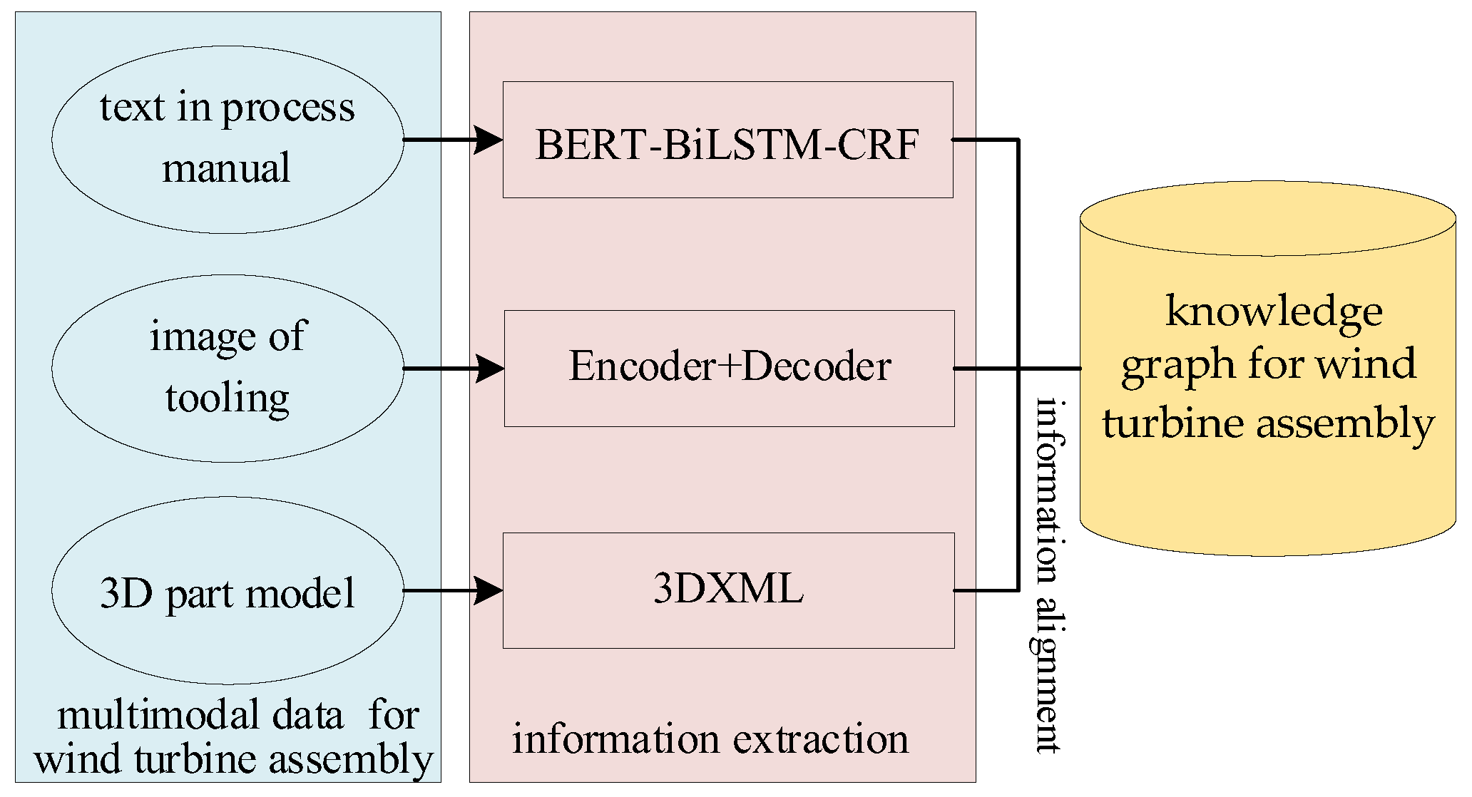
3.1.2. Knowledge Extraction for Multimodal Data

In wind turbine assembly, an overall framework for extracting knowledge from multimodal data is shown in Figure 2. Multimodal data includes text in the process manual, the image of tooling, and the 3D model. Also, information extraction methods are divided into three types, including textual data knowledge extraction, knowledge extraction for image data, and information extraction for the 3D model, respectively. The implementation details of the framework are discussed below in three parts.
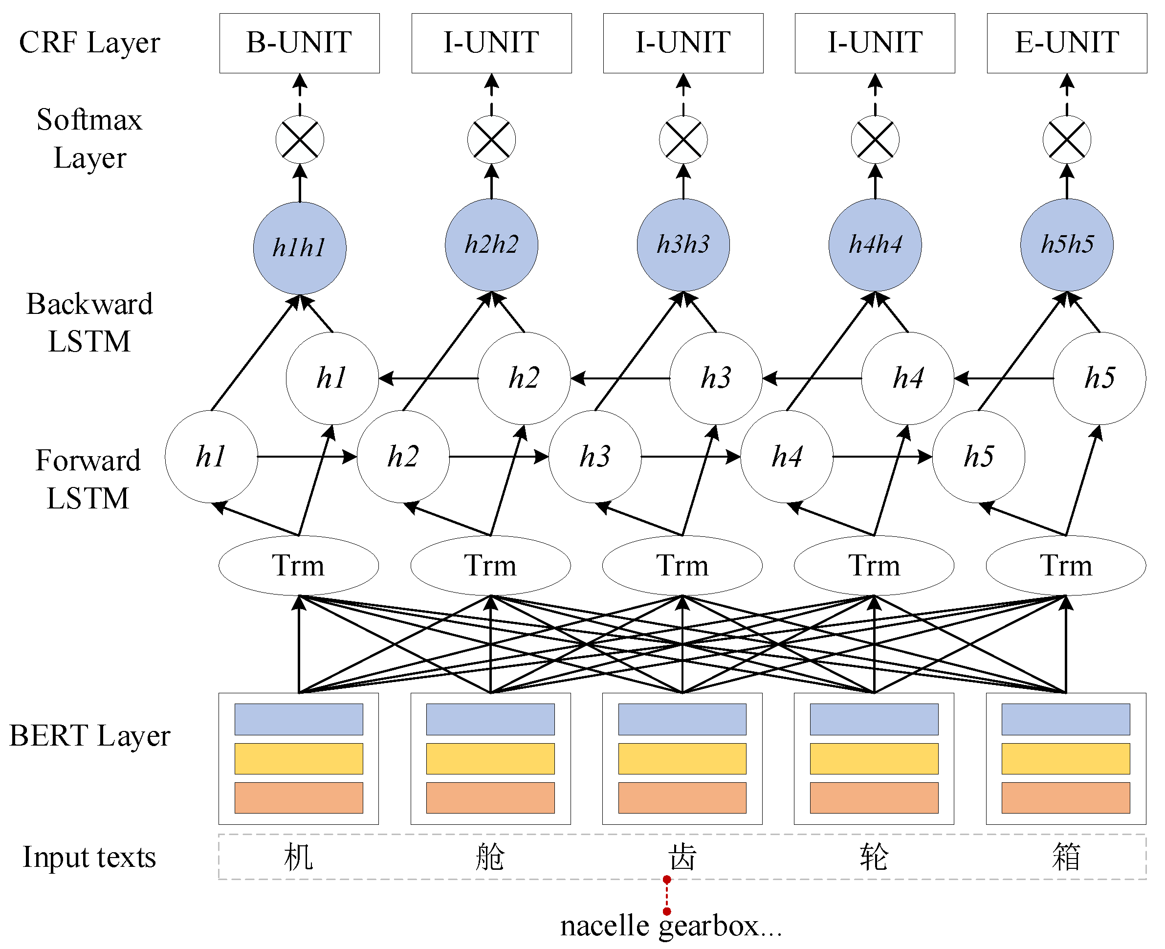
  • Textual Data Knowledge Extraction
The text in the process manual is divided into general assembly text data and BOM (bill of materials) for assembly. On the one hand, the general assembly text data are extracted by designing the BERT-BiLSTM-CRF model, as shown in Figure 3. First, the BERT model is used to obtain word vectors for each input character from the annotated corpus. Next, a sequence of these output word vectors is passed into the BiLSTM layer for semantic encoding to obtain global sequence features. Based on this, the CRF (conditional random fields) layer decodes the output of the BiLSTM layer to produce the predicted label sequences. Then, entities are extracted and classified from the label sequences to obtain the final entity recognition results. Taking the text “nacelle gearbox…” in the assembly manual as an example, after labeling the text by the BIESO mode, the entity is labeled as {B-UNIT, I-UNIT, I-UNIT, I-UNIT, E-UNIT}, where a unit represents the assembly unit.
On the other hand, BOM for assembly shows the relationships of dependencies between wind turbine components. The BOM data in the ERP system can be accessed by calling the API (application programming interface) via python. Furthermore, the knowledge graph can be directly generated by incorporating the inherent dependencies from the BOM.
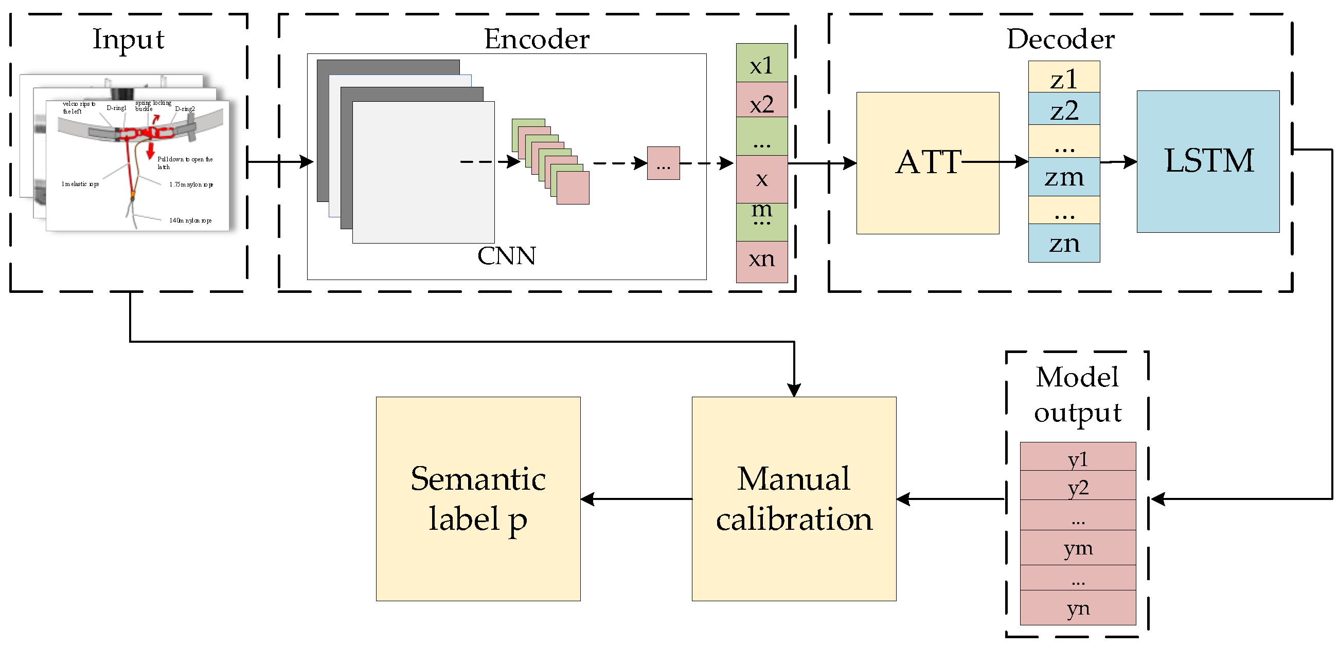
  • Knowledge Extraction for Image Data
The semantic labels of the assembly image are extracted using an encoder-decoder architecture as shown in Figure 4.
Specifically, the image is firstly fed into the encoder part. Then, the feature map is generated by the convolutional neural network (CNN) layer, which can extract the features at m position of the image. The height and width of the feature map are set to 14, the number of channels is 256, the feature vector dimension D = 256, and m = 14 × 14 = 196. The ATT mechanism is added to decode the feature results.
Z t = m = 1 n α t , m x m
αt,m denotes the weight share of the image features at the mth position at stage t of the encoding. The feature result is obtained as Zt. It is used as an input to the LSTM to generate hidden variables. In turn, the output of the model is yt. Considering the issue of semantic labeling output integrity, a manual calibration step needs to be added, including expert experience combined with the model generation. Finally, the output result is p.
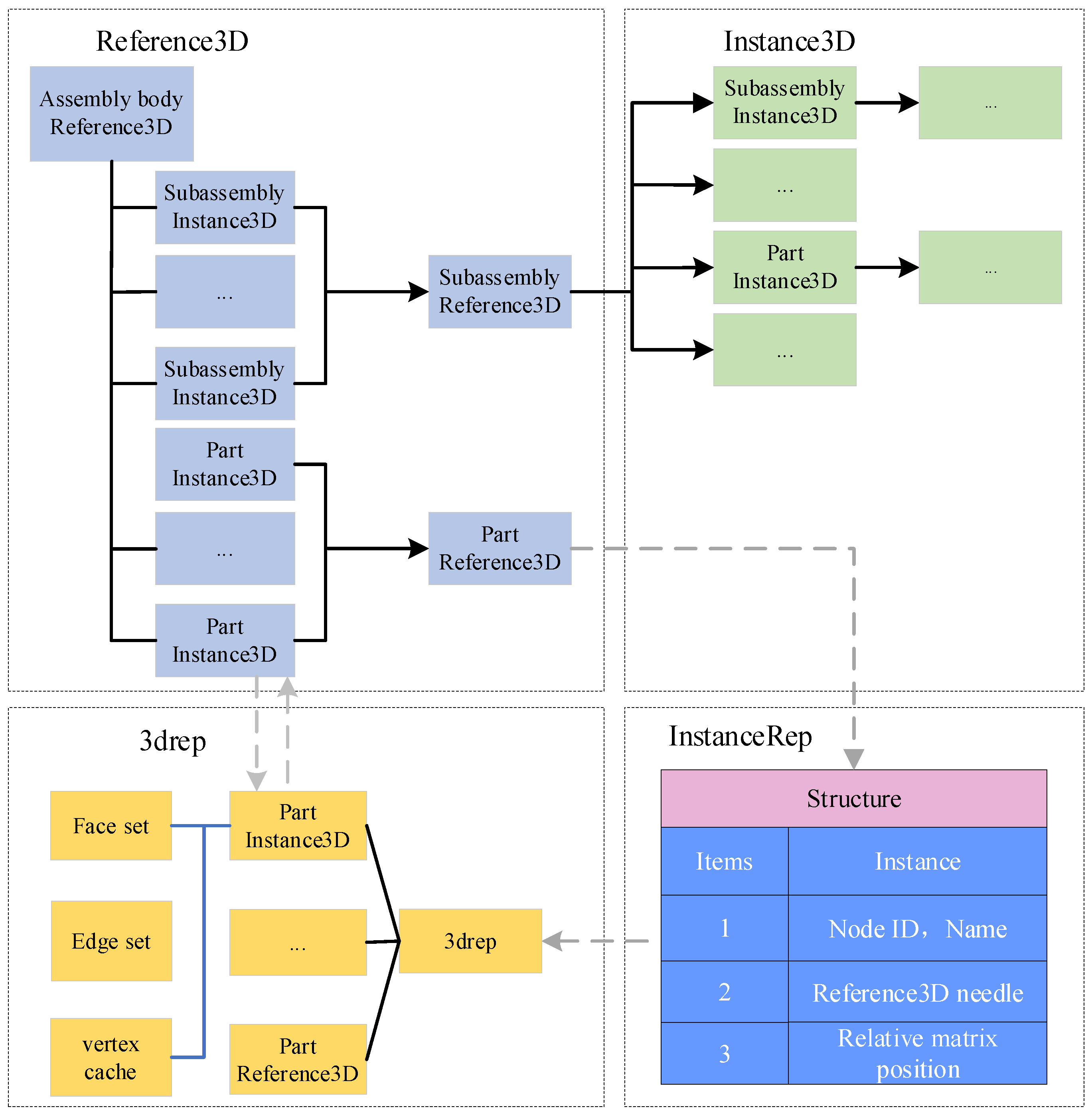
  • Information extraction for 3D models
The structure information of the 3D model of the wind turbine consists of <ProductStructure> as the root node, including the node’s ID, pointer to Reference3D, and relative matrix position. Its leaf nodes are divided into four categories, including <Reference3D>, <Instance3D>, <ReferenceRep>, and <InstanceRep>. Reference3D nodes and Instance3D nodes have no obvious affiliation. The total assembly, as an assembly structure of multiple subassemblies, is identified as Reference3D, but a subassembly can also be an assembly of multiple parts, so its identity can be either Instance3D or Reference3D. In addition, information related to a part or assembly is stored in the ReferenceRep to indicate a reference to the part or assembly. It usually contains a unique ID value for identification and referencing in the file. Its data structure is shown in Figure 5.

3.2. Knowledge Graph-Based Assembly Sequence Retrieval and Reasoning for Wind Turbine

In this section, an assembly sequence retrieval and reasoning method for wind turbines based on an assembly process knowledge graph is proposed. Its design steps for the assembly sequence generation are accomplished, including assembly process items based on BERT-GMN, graph similarity calculation based on SWRL, assembly semantic rule generation, and automatic generation of subassembly sequences. It is discussed in detail below.

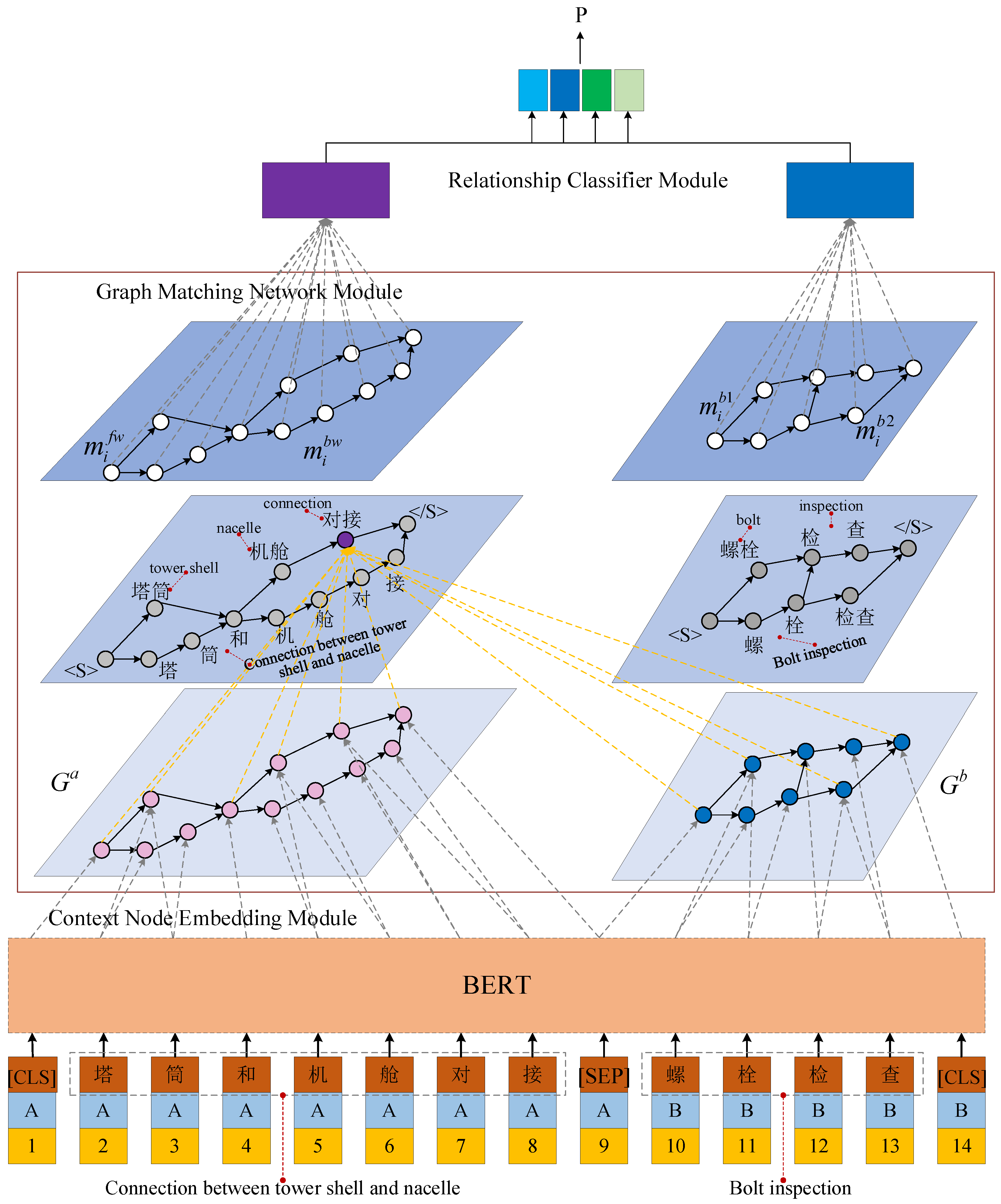
3.2.1. Retrieval of Similar Assembly Process Items Based on BERT-GMN

In particular, for the retrieval of similar assembly process items, a graph neural network is utilized to compute the similarity between assembly nodes and relationships to determine whether two graphs or local subgraphs are similar. Combined with the BERT in Section 3.1.2, BERT-GMN is proposed to retrieve similar assembly process items, as shown in Figure 6. The modules included from bottom to top in the figure are context node embedding, graph-matching neural network, and relationship classifier, respectively, where the BERT encodes the assembly text.
  • Context Node Embedding Module
For any node vi in the graph, there is a difference between the embedding of the initial nodes and the embedding of the intermediate context nodes. Specifically, the initial nodes need to first concatenate the assembly statements to form a new sequence S = { [ C L S ] , c a 1 , , c t a a , [ S E P ] , c 1 b , , c t b b , [ S E P ] } . Its output will be used as input to the BERT model, resulting in a context-embedded representation of each character as c C L S , c 1 a , , c t a a , c S E P , c 1 b , , c t b b , , c S E P . Assuming that node vi consists of ni consecutive character symbols { c s i , c s i + 1 , , c s i + n i + 1 } 1 , for each character c s i + k c s i + k , a feature score vector u ^ s i + k is computed using a feed-forward network. Then, softmax is used for normalization. The corresponding character embedding c s i + k is weighted to obtain the initial node embedding V i = k = 0 n 1 u s i + k c s i + k where denotes the product of the elements of two vectors.
  • Graph Matching Neural Network Module
The context node is embedded in v i as the initial representation of the node h i 0 . Then, its representation from one layer to the next is updated and organized into two steps.
Message passing: each node v i in G a aggregates messages m i f w and m i b w from neighboring nodes.
m i f w = v j N f w ( v i ) a i j ( W f w h j l 1 ) , m i b w = v k N b w ( v i ) a i k ( W b w h k l 1 )
Also, it aggregates all the node information m i b 1 and m i b 2 in G b .
m i b 1 = v m V b a i m ( W f w h m l 1 ) , m i b 2 = v q V b a i q ( W b w h q l 1 )
α i j , α i k , α i m , α i q are the attention parameters. When the match value exceeds the similarity threshold, the m i s e l f m i c r o s s . The reason for the two assembly nodes not being exactly equal is that node v i can only aggregate messages from its neighboring nodes in G a , while it can aggregate messages from all nodes in G b .
Representing updates: after aggregating the messages, each node v i updates its representation from h i l 1 to h i l , which can be first compared to m i s e l f and m i c r o s s using the multi-view cosine distance.
d k = cos i n e ( w k cos m i s e l f , w k cos m i c r o s s )
h i l = F E N ( m i s e l f , d i )
where k { 1,2 , , P } . w k cos is a parameter vector. FEN denotes a two-layer feedforward network. After the step of updating the node representation L, a graph-aware representation h i L of each node v i will be obtained.
  • Relational Classifier Module
A similarity between assembly clauses or assembly sequence subgraphs can be predicted using two graph-level representations, G a and G b .
p = F E N ( g a , g b , g a g b , | g a g b | )
where p [ 0,1 ] , the training objective is to minimize the binary cross-entropy loss.

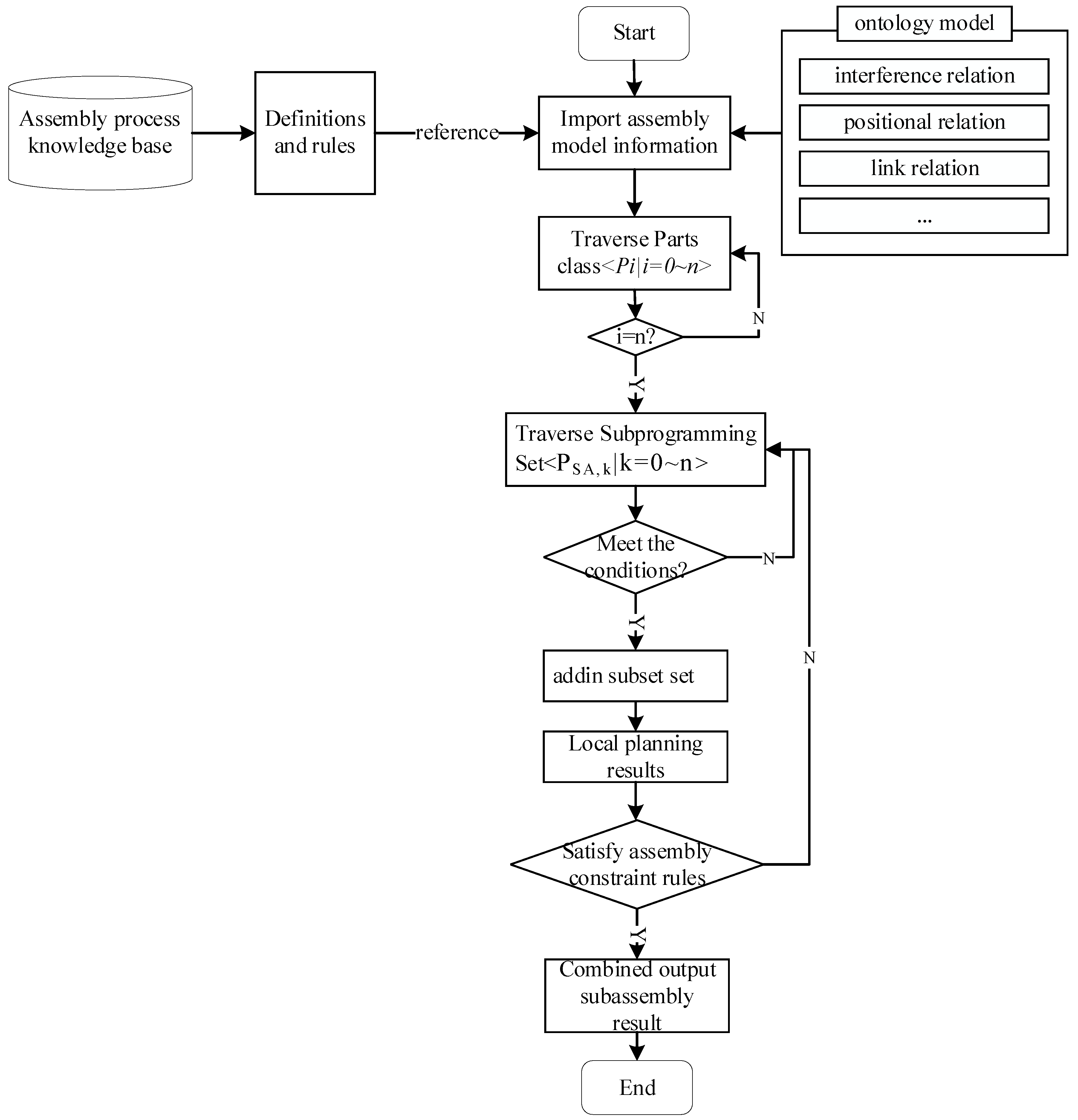
3.2.2. Reasoning about Instance Items of Assembly Process Based on SWRL

Not all assembly units or assembly types can find similar process items in the assembly library. For a new assembly, designers are required to redesign the assembly process. Therefore, the design is based on the SWRL to construct the inference rules for the semantics of assembly operations and generate the entities describing the process of executing assembly operations, the assembly resource entities, and the relationships between them to complete the design of process steps for a new assembly.
  • Assembly Semantic Rule Generation
The assembly relationship defines the freedom degree of assembly between parts. This expresses the restriction of various positional relationships to different components so as to judge the disassembly level of the components. A series of assembly specifications, such as assembly degrees of freedom GF and cooperative relationship CR, are obtained based on the positional and cooperative relationships between the assembled components.
Taking the cooperative relationship of the YZ plane and the positional relationship of the Y-axis direction as an example, the corresponding assembly specification obtained by the combination of other cooperative and positional relationships can also be defined as follows, R 1 : p r f p F A r C R p . h a s C R r f G F r . h a s G F f p . h a s G F f . In R1, the freedom degree of limitation relationships of the mutually supported parts in the SWRL are described. If p F A and there is a restricted freedom degree of relation between CR(r) and GF(f), then FA(p), GF(f), and hasGF(p, f) are held by the OWL (ontology wed language) assertion formula rule.
Assembly coupling rules are used to assist in improving the stability and feasibility of the installation process. To ensure a reasonable assembly sequence, assembly coupling rules R2~R4 are given to generate a collection of couplings.
R 2 : ( p 1 ) ( p 2 ) ( p 1 S P N p 2 S A a n d P p 1 . N e x t ( p 2 ) p 1 . S C R ( p 2 ) )
R 3 : ( p 1 ) ( p 2 ) ( p 1 S P N p 2 S A a n d P p 1 . N e x t ( p 2 ) p 1 . S A P ( p 2 ) )
R 4 : ( p 1 ) ( p 2 ) ( p 1 S P N p 2 S A a n d P p 1 . N e x t ( p 2 ) p 1 . S C P ( p 1 ) )
R2 − R4 describes the coupling relationship between parts. If S P N ( p 1 ) and S A a n d P have a coupling relationship, then the OWL assertion formula holds for S A a n d P and S C R ( p 2 ) , S A P ( p 2 ) , and S C P p 1 .
The assembly interference relationship reflects the mutual interference status of two parts in the spatial coordinate system during the assembly process. As a pre-step of subassembly sequence generation, it is necessary to accurately obtain the interference information between the parts. There are the following OWL rules to define the interference relationship.
R 5 : p p 1 p 2 p 3 f p F A p 1 S A a n d P p 2 S A a n d P p 3 S A a n d P p . h a s B e g i n p 2 p . h a s E n d p 3 p 1 = p 2 f G M O i p . h a s G M O f p 1 . S I R i p 3
R 6 : ( p ) ( p 1 ) ( p 2 ) ( p 3 ) ( f ) ( p F A p 1 S A a n d P p 2 S A a n d P p 3 S A a n d P p . h a s B e g i n ( p 2 ) p . h a s E n d ( p 3 ) p 1 = p 3 f G M O i p . h a s G M O ( f ) p 1 . S I R o ( p 2 ) )
where both R5 and R6 describe the interference of the combination of parts. In the formula, considering the idea of detachable and mountable, the interference direction is also divided into positive and negative where i represents the positive direction and o represents the negative direction. Taking R5 as an example, if there is interference between F A ( p ) and G M O i , the parts p belonging to the subassembly F A are used as the reference parts for judging the interference location and, then, the set of F A ( p ) , S A a n d p , and S I R o p , p hold by the assertion formula rule.
  • Automatic generation of subassembly sequences
In the case of similar assemblies, partial modifications are made based on existing sequences. If it is a new product, the relationships between the different concepts in an assembly information representation model are used. Also, the data are transferred to the subassembly sequence generation algorithm through a rule-based reasoning method. If the local planning results meet the assembly constraint rules, the subassembly sequences are filtered out to find a reasonable sequence of eligible subassemblies. Finally, for the demand of assembly optimization, the global optimal result is output. The steps and flow chart are shown in Figure 7.
S t e p 1 : Import the initial parameters of the algorithm, including multiple assembly constraint relationships based on the ontology representation.
S t e p 2 : The initial parameters of the algorithm are set based on the rules defined in the assembly process knowledge base, such as the maximum number of iterations N_max, the part class Parts, and the container class P S A retains the subassembly sequence.
S t e p 3 : Build an ontology model of the assembly.
S t e p 4 : Iterate through the Parts class.
S t e p 5 : Iterate through P S A and add the queue information from the Parts class to the sub-planning collection.
S t e p 6 : If the conditional judgment function is met, a queue of subassemblies of the part class Parts is created. If not, the next part in the subassembly is traversed.
S t e p 7 : Initial generation of localized planning results.
S t e p 8 : Query from the ontology model whether the current local sequence planning result satisfies the assembly constraint rules, including S I R , S P R , S C R . If not, go back to the sub-planning set traversal.
S t e p 9 : Outputs the results of the calculations for the sequence planning of this subassembly.
  • Final Assembly Sequence Prioritization Calculation
After obtaining the subassembly outputs, the overall assembly planning needs to ensure the geometric feasibility of the assembly sequence, including the geometric feasibility of the final assembly sequence, the stability of the assembly operations, the cohesiveness of the assembly process, and the number of assembly reorientations.
(1)
The geometric feasibility of the final assembly sequence
When a final assembly consists of n subassemblies, it refers to the case where a subassembly S A i 0 < i < n in the final assembly translates to infinity along a certain assembly direction and interferes with other subassemblies.
(2)
The stability of the assembly operations
With all known assembly sequences being feasible, both the stability of the connection relationships between parts and the stability of the gravitational direction affecting the assembly process needs to be considered. The stability of the connection relationship is expressed:
S c = i = 1 n c i , j
c i , j denotes the number of unstable connections between two components. The gravity direction stability calculation is expressed as follows.
S s = i = 1 n s i , j
In summary, the stability of the assembly operation of the general assembly sequence can be obtained as follows.
f s = 1 i = 1 n ( c i , j + s i , j ) + 1 = 1 N S + 1
(3)
The cohesiveness of the assembly process
It is the utilization of the same set of assembly process equipment in the assembly process. The number of changes of tools used in the process of successive completion of the coupling of products is N i ( 0 N i n 1 ) , provided that the assembly sequence is determined to be feasible. Based on the principle that the lower the number of changes in the assembly tool, the better the assembly performance. The aggregation affiliation in the assembly process is expressed as follows.
f i = 1 N i + 1
(4)
The number of assembly reorientations
The number of assembly reorientations is the sum of the number of changes in the three axes. The number of assembly reorientations may vary due to sequential differences in the assembly order of different feasible subassemblies. The affiliation number of assembly reorientations in the final assembly sequence can be obtained based on the total number of changes N d ( 0 N d n 2 ) of the final assembly on the three axes.
f o = 1 N d + 1
  • Multi-objective sequence optimization algorithm
Through the analysis of the above multi-objective comprehensive optimization method for wind turbines, the local subassembly sorting results based on the output of the rule generation layer are combined. Then, the final assembly sequence generation algorithm is shown in Algorithm 1.
Algorithm 1 Assembly sequence generation algorithm
Input: list i//Serial information for subassemblies in the list
Output: list AS//Final assembly results after multi-objective sequential optimization
Algorithm GenerateAssemblySequences(List list)
1: list AP = createArrayList()
2: list a = createArrayList()
3: list b = createArrayList()
4: FOR each list Pj, in the list i.P
5: IF list Pj.Bsp = TRUE
6: list b.add(list Pj.ID)
7:    list AS. add(list b)
8:  IF list AS=NULL
9:   FOR each list Pj in the list i.P
10:    IF list Pj.NPR = maxof(list Pj)//Find the maximum number of locational relations
11:       list b. add(listPj.ID)
12:       list AS.add(listb)//Base parts for assembly sequences
13:    WHILE//Iterate over all subassembly sequences
14:      FOR each list b in the list AS
15:      IF list Pi.SA(fg) ≠ NULL
16:      IF list Pi.SA(fs) ≠ NULL
17:      IF list Pi.SA(fp) ≠ NULL
18:      IF list Pi.SA(fo) ≠ NULL
19:      IF list Pi.SA(fr) ≠ NULL
20:    list Pj.add(list b*)
21:  return

4. Case Study

4.1. Case Illustration

In this section, the example of generating the assembly sequence of a VEU-15 wind turbine (from Vestas Production Site in Tianjin, China) is used to validate the effectiveness of the proposed knowledge graph-based approach for the wind turbine assembly sequence. The wind turbine is shown in Figure 8. The part number is shown in Table 2.

4.2. Knowledge Graph Construction and Wind Turbine Assembly Sequence Generation

  • Statistics of assembly process information
The assembly information is obtained from the assembly process text, on-site installation images, and 3D models. Then, the assembly knowledge entities and relationships are extracted as the basis for knowledge reasoning. Table 3 shows the statistics of the wind turbine’s assembly information.
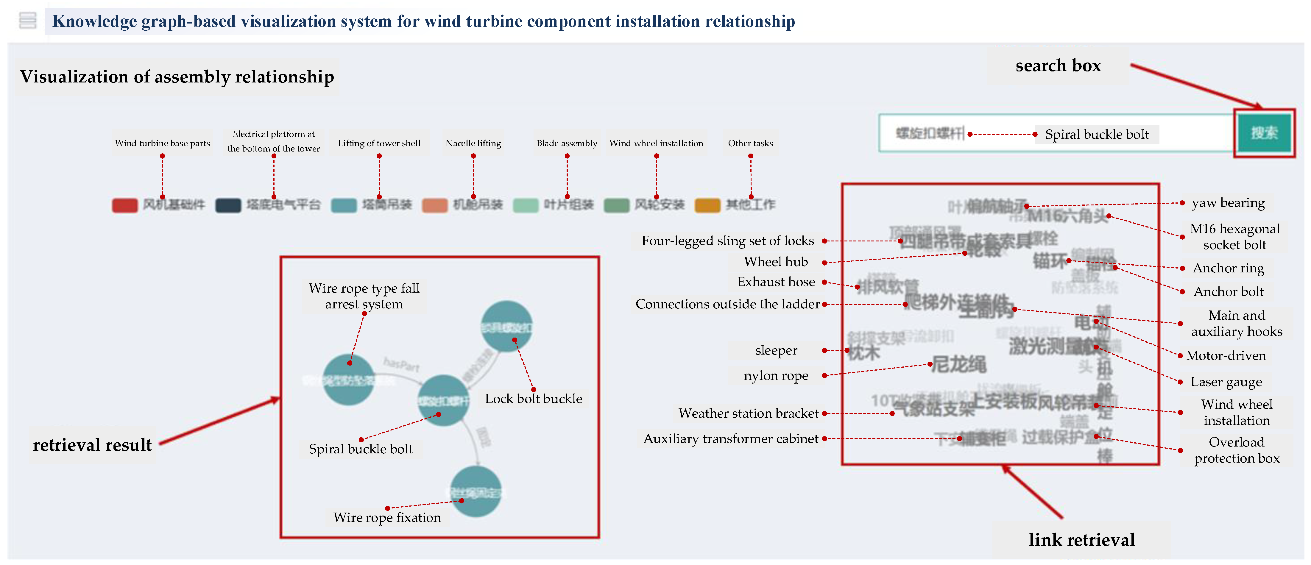
  • Knowledge extraction and knowledge graph generation from assembly information
As the BOM of an assembly contains the relationships of dependencies between the components of a wind turbine, it can be achieved by accessing the BOM data in the ERP system via an API to build the knowledge graph directly. Therefore, only general assembly texts are discussed in this section. For textual entity recognition and relationship extraction models, the labeled corpus is divided into training, validation, and test sets in the ratio of 8:1:1. The entities of other modalities are extracted directly: 10% of them are taken and aggregated with the text entity test data to form the total entities. Meanwhile, in this paper, 10% of the cross-modal relations extracted are manually verified. These results are aggregated with the textual relations test data to become total relationships. To evaluate the accuracy of the extraction results, the F1-score is used for both entities and relationships.
F 1 e n t i t y = 2 × P e n t i t y × R e n t i t y P e n t i t y + R e n t i t y
F 1 l i n k = 2 × P l i n k × R l i n k P l i n k + R l i n k
Precision on Pentity, Plink denotes the ratio of correct entities to recognized entities. Recall on Rentity, Rlink denotes the ratio of the number of correctly recognized entities to the total number of entities. Table 4 gives the overall evaluation of wind turbine multimodal knowledge extraction. It shows that each index reaches more than 0.8, proving that the method is reliable due to its consistency.
The visualization of the assembly knowledge graph of the wind turbine is shown in Figure 9. The relationships include mainly bolted, screwed, hasPart, partOf, HasSubassembly, and SubassemblyOf.
The visualization of component assembly relationships is an important part of knowledge reuse. It ensures that the assemblers select the required knowledge services to accomplish the target planning according to their assembly requirements. The assembly relationship retrieval is shown in Figure 10. In the process of wind turbine installation, the final assembly can be divided into seven parts of subassemblies, which are wind turbine foundation parts, electrical platform at the bottom of the tower, tower hoisting, nacelle hoisting, blade assembly, wind turbine installation, and others. Different subassemblies are indicated by different colors, which represent different labels in Neo4j. These colors can be used to determine which subassemblies belong to an assembly entity node. Taking the assembly part “Spiral buckle bolt” as an example, there are two ways to obtain the assembly process information of this part in the lifting of tower shell. The first one is to input the part to be retrieved in the search box. If the entity of this part exists in the database, the assembly process chain can be obtained successfully. The other method is to obtain the required assembly knowledge by clicking on the part name directly below the search box. After the system matches the filters, the knowledge graph automatically associates the entity nodes and their relationships. As can be seen from Figure 10, the relationship between the “Spiral buckle bolt” and the “Wire rope fixation” is fixed. The relationship between the “Spiral buckle bolt” and the “Wire rope type fall arrest system” is hasPart. The connection method between the “Spiral buckle bolt” and the “Lock bolt buckle” is boltConnection.

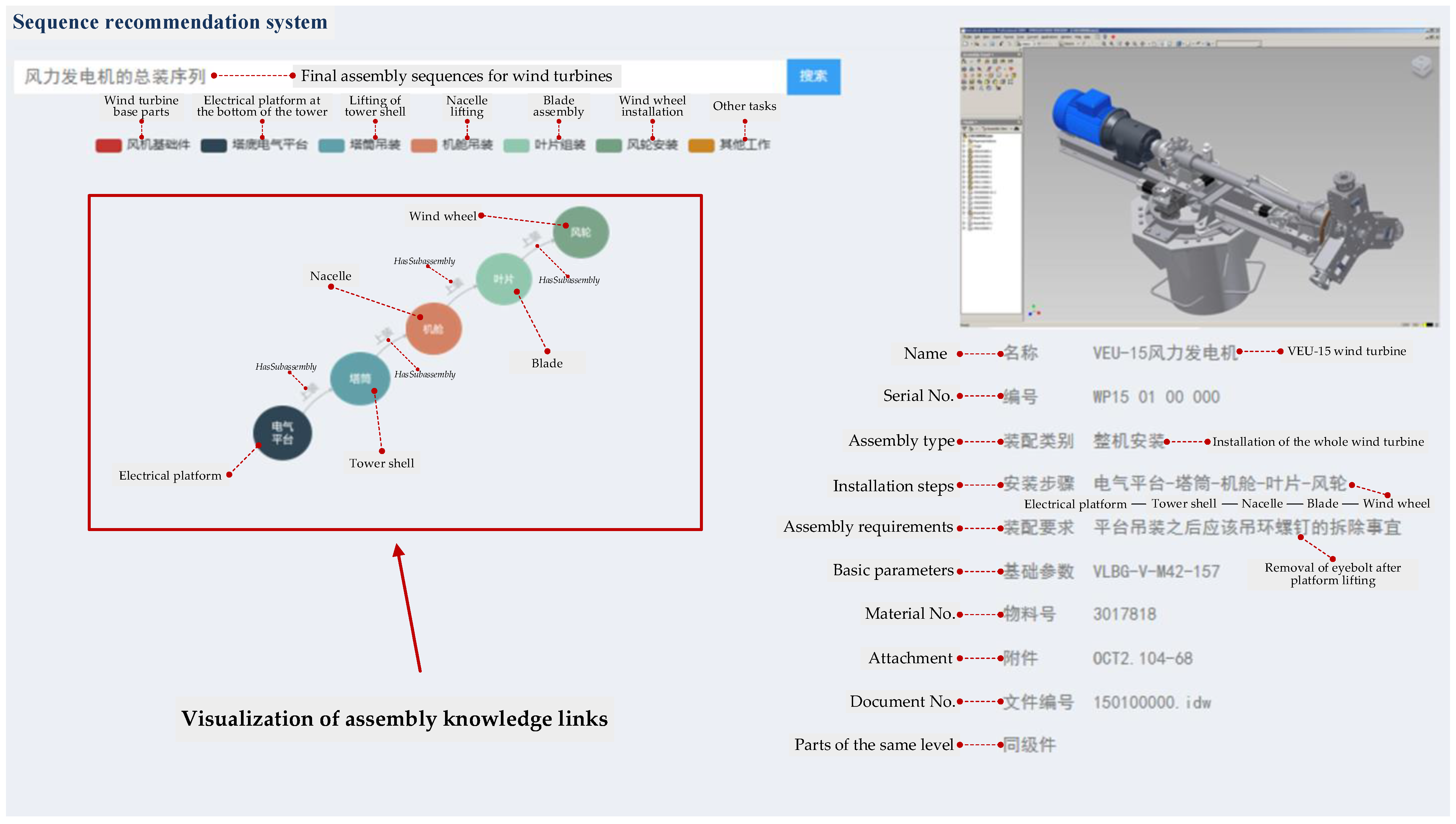
4.3. Knowledge Graph-Based Assembly Sequence Recommendation for Wind Turbine

  • Component assembly relationship rule generation and knowledge reasoning
Firstly, the API functions of the CAD system are utilized to extract the assembly constraint relationships. After extracting the results, the Jena API is used to input the information into the OWL file to realize the instantiation of the assembly information ontology. Through the instantiated fit relationship assertion formulas, the part assembly rules under different preconditions can be obtained.
Next, the extracted assembly information ontology is instantiated to execute the reasoning based on the defined rules. Ontology construction and instantiation reasoning are performed using Protégé, running the algorithms in a Java development environment. Under the premise of determining the geometric feasibility of the assembly, the parameter settings are adjusted according to the assembly requirements for stability affiliation, aggregation affiliation, and reorientation affiliation. Then, the weights are set for the priority relationship levels. Finally, the subassembly sequences planning for the final assembly are obtained. Its generation process is shown in Figure 11. It is shown that three feasible global sequences can be generated. Firstly, sequence 1 is Blade−Tower Shell−Electrical Platform−Nacelle−Wind Wheel. Secondly, sequence 2 is an Electrical Platform−Tower Shell−Nacelle−Blade−Wind Wheel. Thirdly, sequence 3 is a Nacelle−Tower Shell−−Electrical Platform−Blade−Wind Wheel.
By analyzing the sequences of the three wind turbine products obtained above, it can be found that each sequence can meet the assembly requirements of the products. However, from the consideration of comprehensive indexes at the part level, the best assembly sequence is selected as sequence 2, which starts from the electrical platform S_A3. The subsequent parts take this as the center to determine their respective assembly sequences. The global sequence representation based on the knowledge graph is completed by combining subassembly planning, whereby the model information and attribute information of the parts are visualized together, as shown in Figure 12. In general, combining Figure 11 and Figure 12, the proposed methods provide a chance to integrate and utilize data at the assembly stages of the life cycle in wind turbines, so as to better meet the needs of users’ personalized and customized assembly requirements.
  • Optimization of assembly sequences for wind turbines
Under the premise of determining the geometric feasibility of the assembly sequence, it is necessary to further use the optimization algorithm proposed in this paper to determine the advantages and disadvantages of the assembly sequence in terms of assembly reorientation, assembly aggregation, and assembly stability. Then, the classical optimization algorithms, including the Pareto ant colony algorithm [39] and the NSGA-II algorithm [40], are selected as the baseline because the Pareto ant-colony algorithm ensures the rationality and feasibility of the assembly sequence by constructing the feasible solutions of the components in a step-by-step manner. Secondly, the Pareto ant colony will be affected by the heuristic information in the process of selecting the next assembly part, so it will have a greater probability to select those parts to be assembled with a greater value of heuristic information, which is unique to this local search strategy and is conducive to the planning of high-quality assembly sequences. Also, NSGA-II is a classic algorithm in the field of multi-objective optimization. It is renowned for its powerful search capabilities and diverse maintenance, making it an excellent choice for addressing multi-objective problems. In this paper, taking the wind turbine assembly sequence planning as an example, the nacelle, the part with the largest size, is selected as the priority assembly part. In this case, the algorithm’s operating parameters are taken from reference [39,40].
Finally, the TOPSIS (technique for order of preference by similarity to ideal solution) method is introduced to rank the optimization methods for assembly sequences because TOPSIS is a multi-criteria decision-making method that compares the Euclidean distance between three experimental algorithms and ideal or anti-ideal solutions. Also, it determines the relative merits of each algorithm by calculating the relative closeness of each assembly sequence’s solution to the ideal sequence, taking the first three near-optimal solutions from each of the three algorithms, including the proposed algorithm, the Pareto ant colony algorithm, and the NSGA-II algorithm. Thus, the TOPSIS method is used to rank these methods. The actual assembly sequences for each method are shown in Table 5. The results of the TOPSIS ranking are shown in Table 6.
Each solution in the computational results represents a feasible assembly scheme. The optimal solution k3 of this paper’s method among these assembly solutions has an assembly reorientation affiliation of 0.95, corresponding to two reorientations. The assembly aggregation affiliation feedback is the number of tool changes in the execution of assembly steps. The optimal solution of this paper’s method aggregation affiliation is 0.51, which corresponds to the number of tool changes in the assembly process of six times. This is the least among the assembly schemes. From the point of view of the actual assembly of the wind turbine, even if different assembly programs are selected, the connection between the parts will not be easily changed. Therefore, the performance of the stability affiliation of the three algorithms is in proximity. It can be seen that all three methods can provide a wider decision space for decision makers. They can solve different practical problems according to the users’ assembly needs. The final result of solving the multi-objective assembly sequence planning problem is a set of approximate optimal solutions. In practice, it is necessary to choose a solution that makes each optimization objective as optimal as possible. The method in this paper achieves optimization in the TOPSIS multiple assembly scheme ranking.
Overall, in the manner of the new generation of information technologies and methods, including the construction of knowledge graphs in wind turbine assembly and knowledge-driven assembly sequence recommendations for the wind turbine, the assembly workload of each component will be reduced in the development workload of the whole wind turbine. It can be noticed that various assembly data related to wind turbine assembly scattered in the assembly workshop are effectively integrated and utilized by multi-process assembly information modeling and knowledge extraction. It provides powerful support for workers to share, query, and trace the assembly knowledge of wind turbines. In addition, the sequences obtained by knowledge-driven assembly sequences are superior and more efficient than traditional manual experience and similarity matching methods, by combining the wind turbine-specific assembly requirements and the optimization degree of several assembly evaluation indexes. It provides a viable means for assisting workers in designing assembly sequences with multi-configuration requirements.

5. Conclusions and Future Work

A knowledge graph-based approach for assembly sequence recommendations for wind turbine is proposed in this paper. Firstly, an assembly information representation model and knowledge extraction methods for different modal data are designed to construct a knowledge graph for wind turbine assembly. Secondly, a knowledge graph-based reasoning method for wind turbine assembly sequences is proposed. For the existing assembly knowledge items in the assembly knowledge base, similar assembly process item retrieval is realized based on the BERT-GMN model. For new assemblies without assembly experience support, the reasoning rules of assembly process instance items are proposed to analyze the set of assertion formulas for the support relationship, coupling relationship, and interference relationship. Considering the multi-objective evaluation index optimization, a multi-objective sequence optimization algorithm is designed. Finally, the comprehensive evaluation metrics for both entities and links in knowledge extraction tasks reach above 0.8, proving that the consistency of different modal knowledge extraction methods is reliable. The effectiveness of the multi-source information representation of parts and optimal sequence reasoning is verified using the VEU-15 wind turbine as a case. In the comparison of the three methods, the proposed method achieves better results when assembly sequence reasoning under assembly reorientation, assembly aggregation, and assembly stability are considered simultaneously.
Although the proposed method shows superior results for assembly sequence recommendations for wind turbines, it still has some limitations. It is possible to extend the assembly information representation model, which currently focuses on geometric constraints. In fact, in complicated assembly scenarios, process constraints also form various limitations on the manufacturing process, including the manufacturing process, machining accuracy, and material selection related to PFEP (plan for every part). Therefore, by considering more constraints, the extended assembly information representation model may be made more comprehensive and accurate to adapt to more complicated products. Also, there is insufficient consideration of the dynamics and complexity of factors of production. The introduction of temporal information in subsequent assembly sequence recommendations is worth investigating, such as the rotation of assembly personnel and the updating of assembly equipment, to meet needs in complicated assembly situations.

Author Contributions

Conceptualization, M.L. and B.Z.; Data curation, M.L. and J.L.; Funding acquisition, B.Z., J.L., X.L. and J.B.; Methodology, M.L., B.Z. and J.L.; Software, M.L. and B.Z.; Supervision, B.Z.; Validation, M.L., B.Z. and J.L.; Visualization, M.L. and X.L.; Writing—original draft, M.L.; Writing—review and editing, X.L. and J.B. All authors have read and agreed to the published version of the manuscript.

Funding

This work is supported by the National Key Research and Development Program of China (No. 2019YFB1706300), the Municipal Natural Science Foundation of Shanghai (No. 21ZR1400800), the Shanghai Rising-Star Plan (Yangfan Program) from the Science and Technology Commission of Shanghai Municipality (No. 22YF1400200), and the Fundamental Research Funds for the Central Universities and Graduate Student Innovation Fund of Donghua University (No. CUSF-DH-D-2021043).

Data Availability Statement

The data that have been used are confidential.

Conflicts of Interest

The authors declare no conflict of interest.

References

  1. Zheng, P.; Chen, C.-H.; Shang, S. Towards an Automatic Engineering Change Management in Smart Product-Service Systems—A DSM-Based Learning Approach. Adv. Eng. Inform. 2019, 39, 203–213. [Google Scholar] [CrossRef]
  2. Lu, Y.; Xu, X.; Wang, L. Smart Manufacturing Process and System Automation—A Critical Review of the Standards and Envisioned Scenarios. J. Manuf. Syst. 2020, 56, 312–325. [Google Scholar] [CrossRef]
  3. Liu, J.; Sun, Q.; Cheng, H.; Liu, X.; Ding, X.; Liu, S.; Xiong, H. The State-of-the-Art, Connotation and Developing Trends of the Products Assembly Technology. J. Mech. Eng. 2018, 54, 2–28. [Google Scholar] [CrossRef]
  4. Ji, Z. Intelligent Manufacturing—Main Direction of “Made in China 2025”. China Mech. Eng. 2015, 26, 2273. [Google Scholar]
  5. Kumar, G.A.; Bahubalendruni, M.V.A.R.; Vara Prasad, V.S.S.; Ashok, D.; Sankaranarayanasamy, K. A Novel Geometric Feasibility Method to Perform Assembly Sequence Planning through Oblique Orientations. Eng. Sci. Technol. Int. J. 2022, 26, 100994. [Google Scholar] [CrossRef]
  6. Tao, C.; Chunhui, L.; Hui, X.; Zhiheng, Z.; Guangyue, W. A Review of Digital Twin Intelligent Assembly Technology and Application for Complex Mechanical Products. Int. J. Adv. Manuf. Technol. 2023, 127, 4013–4033. [Google Scholar] [CrossRef]
  7. Mahajan, R.; Sankman, B. 3D Packaging Architectures and Assembly Process Design. In 3D Microelectronic Packaging: From Fundamentals to Applications; Li, Y., Goyal, D., Eds.; Springer Series in Advanced Microelectronics; Springer International Publishing: Cham, Switzerland, 2017; pp. 17–46. ISBN 978-3-319-44586-1. [Google Scholar]
  8. Yi, Y.; Yan, Y.; Liu, X.; Ni, Z.; Feng, J.; Liu, J. Digital Twin-Based Smart Assembly Process Design and Application Framework for Complex Products and Its Case Study. J. Manuf. Syst. 2021, 58, 94–107. [Google Scholar] [CrossRef]
  9. Eschen, H.; Kötter, T.; Rodeck, R.; Harnisch, M.; Schüppstuhl, T. Augmented and Virtual Reality for Inspection and Maintenance Processes in the Aviation Industry. Procedia Manuf. 2018, 19, 156–163. [Google Scholar] [CrossRef]
  10. Chen, Z.; Bao, J.; Zheng, X.; Liu, T. Assembly Information Model Based on Knowledge Graph. J. Shanghai Jiaotong Univ. 2020, 25, 578–588. [Google Scholar] [CrossRef]
  11. Shi, X.; Tian, X.; Gu, J.; Yang, F.; Ma, L.; Chen, Y.; Su, T. Knowledge Graph-Based Assembly Resource Knowledge Reuse towards Complex Product Assembly Process. Sustainability 2022, 14, 15541. [Google Scholar] [CrossRef]
  12. Zhou, B.; Bao, J.; Chen, Z.; Liu, Y. KGAssembly: Knowledge Graph-Driven Assembly Process Generation and Evaluation for Complex Components. Int. J. Comput. Integr. Manuf. 2022, 35, 1151–1171. [Google Scholar] [CrossRef]
  13. Li, X.; Zhang, S.; Huang, R.; Huang, B.; Xu, C.; Kuang, B. Structured Modeling of Heterogeneous CAM Model Based on Process Knowledge Graph. Int. J. Adv. Manuf. Technol. 2018, 96, 4173–4193. [Google Scholar] [CrossRef]
  14. Wang, M.; Wang, H.; Li, B.; Zhao, X.; Wang, X. Survey on Key Technologies of New Generation Knowledge Graph. J. Comput. Res. Dev. 2022, 59, 1947–1965. [Google Scholar] [CrossRef]
  15. Cheng, B.; Zhu, J.; Guo, M. MultiJAF: Multi-Modal Joint Entity Alignment Framework for Multi-Modal Knowledge Graph. Neurocomputing 2022, 500, 581–591. [Google Scholar] [CrossRef]
  16. Ding, Y.; Yu, J.; Liu, B.; Hu, Y.; Cui, M.; Wu, Q. MuKEA: Multimodal Knowledge Extraction and Accumulation for Knowledge-Based Visual Question Answering. In Proceedings of the IEEE/CVF Conference on Computer Vision and Pattern Recognition, New Orleans, LA, USA, 19–20 June 2022; pp. 5089–5098. [Google Scholar]
  17. Zhou, B.; Hua, B.; Gu, X.; Lu, Y.; Peng, T.; Zheng, Y.; Shen, X.; Bao, J. An End-to-End Tabular Information-Oriented Causality Event Evolutionary Knowledge Graph for Manufacturing Documents. Adv. Eng. Inform. 2021, 50, 101441. [Google Scholar] [CrossRef]
  18. Liu, P.; Qian, L.; Zhao, X.; Tao, B. The Construction of Knowledge Graphs in the Aviation Assembly Domain Based on a Joint Knowledge Extraction Model. IEEE Access 2023, 11, 26483–26495. [Google Scholar] [CrossRef]
  19. Wen, Y.; Luo, B.; Zhao, Y. IMKGA-SM: Interpretable Multimodal Knowledge Graph Answer Prediction via Sequence Modeling. arXiv 2023, 1–12. [Google Scholar] [CrossRef]
  20. Bahubalendruni, M.V.A.R.; Gulivindala, A.K.; Varupala, S.S.V.P.; Palavalasa, D.K. Optimal Assembly Sequence Generation through Computational Approach. Sādhanā 2019, 44, 174. [Google Scholar] [CrossRef]
  21. Bortolini, M.; Ferrari, E.; Gamberi, M.; Pilati, F.; Faccio, M. Assembly System Design in the Industry 4.0 Era: A General Framework. IFAC-PapersOnLine 2017, 50, 5700–5705. [Google Scholar] [CrossRef]
  22. Anthony, L.; Regli, W.C.; John, J.E.; Lombeyda, S.V. An Approach to Capturing Structure, Behavior, and Function of Artifacts in Computer-Aided Design. J. Comput. Inf. Sci. Eng. 2001, 1, 186–192. [Google Scholar] [CrossRef]
  23. Kopena, J.B.; Regli, W. Functional Modeling of Engineering Designs for the Semantic Web. IEEE Data Eng. Bull. 2003, 26, 55–61. [Google Scholar]
  24. Wang, X.; Ong, S.K.; Nee, A.Y.C. A Comprehensive Survey of Augmented Reality Assembly Research. Adv. Manuf. 2016, 4, 1–22. [Google Scholar] [CrossRef]
  25. Chen, X.; Gao, S.; Yang, Y.; Zhang, S. Multi-Level Assembly Model for Top-down Design of Mechanical Products. Comput.-Aided Des. 2012, 44, 1033–1048. [Google Scholar] [CrossRef]
  26. Zhou, W.; Zheng, J.; Wang, J. Nested Partitions Method for Assembly Sequences Merging. Expert. Syst. Appl. 2011, 38, 9918–9923. [Google Scholar] [CrossRef]
  27. Gao, S.; Jin, R.; Lu, W. Design for Manufacture and Assembly in Construction: A Review. Build. Res. Inf. 2020, 48, 538–550. [Google Scholar] [CrossRef]
  28. Duan, G.; Shen, Z.; Liu, R. An MBD Based Framework for Relative Position Accuracy Measurement in Digital Assembly of Large-Scale Component. Assem. Autom. 2019, 39, 685–695. [Google Scholar] [CrossRef]
  29. Xu, Z.; Liu, H.; Li, J.; Zhang, Q.; Tang, Y. CKGAT: Collaborative Knowledge-Aware Graph Attention Network for Top-N Recommendation. Appl. Sci. 2022, 12, 1669. [Google Scholar] [CrossRef]
  30. Champatiray, C.; Samal, S.; Bahubalendruni, M.V.A.R.; Mahapatra, R.N.; Mishra, D.; Balabantaray, B.K. Modified Cat Swarm Optimization for Optimal Assembly Sequence Planning Problems. Int. J. Perform. Eng. 2022, 18, 289. [Google Scholar] [CrossRef]
  31. Shen, X.; Liu, S.; Zhang, C.; Bao, J. Intelligent Material Distribution and Optimization in the Assembly Process of Large Offshore Crane Lifting Equipment. Comput. Ind. Eng. 2021, 159, 107496. [Google Scholar] [CrossRef]
  32. Han, Z.; Mo, R.; Hao, L. Clustering and Retrieval of Mechanical CAD Assembly Models Based on Multi-Source Attributes Information. Robot. Comput.-Integr. Manuf. 2019, 58, 220–229. [Google Scholar] [CrossRef]
  33. Liu, C.; Zhang, F.; Zhang, H.; Shi, Z.; Zhu, H. Optimization of Assembly Sequence of Building Components Based on Simulated Annealing Genetic Algorithm. Alex. Eng. J. 2023, 62, 257–268. [Google Scholar] [CrossRef]
  34. Xie, Z.; Du, J.; Chen, Q.; Wang, X. Enhancing the Labor Division in the Balancing of Apparel Assembly Lines with Parallel Workstation through an Improved Ant Colony Algorithm. J. Eng. Fibers Fabr. 2021, 16, 15589250211055784. [Google Scholar] [CrossRef]
  35. Li, F.; Yang, C.; Shao, J. Research on Ant Colony Algorithm for Wing Assembly Sequence Planning. In Proceedings of the 2021 2nd International Conference on Intelligent Computing and Human-Computer Interaction (ICHCI), Shenyang, China, 17–19 November 2021; pp. 175–178. [Google Scholar]
  36. Chaudhari, P.; Thakur, A.K.; Kumar, R.; Banerjee, N.; Kumar, A. Comparison of NSGA-III with NSGA-II for Multi Objective Optimization of Adiabatic Styrene Reactor. Mater. Today Proc. 2022, 57, 1509–1514. [Google Scholar] [CrossRef]
  37. Ehsaeyan, E.; Zolghadrasli, A. FOA: Fireworks Optimization Algorithm. Multimed. Tools Appl. 2022, 81, 33151–33170. [Google Scholar] [CrossRef]
  38. Fountas, N.A.; Kechagias, J.D.; Vaxevanidis, N.M. Optimization of Selective Laser Sintering/Melting Operations by Using a Virus-Evolutionary Genetic Algorithm. Machines 2023, 11, 95. [Google Scholar] [CrossRef]
  39. Dunford, R.; Su, Q.; Tamang, E. The Pareto Principle. Plymouth Stud. Sci. 2014, 7, 140–148. [Google Scholar]
  40. Deb, K.; Pratap, A.; Agarwal, S.; Meyarivan, T. A Fast and Elitist Multiobjective Genetic Algorithm: NSGA-II. IEEE Trans. Evol. Comput. 2002, 6, 182–197. [Google Scholar] [CrossRef]
Figure 1. Assembly information representation model. Of these, the different color boxes contain information related to the assembly. Arrows with information indicate multiple relationships.
Machines 11 00930 g001
Figure 2. An overall framework for knowledge extraction from wind turbine multimodal data.
Machines 11 00930 g002
Figure 3. Workflow of knowledge extraction based on BERT-BiLSTM-CRF.
Machines 11 00930 g003
Figure 4. Workflow of semantic label extraction for image data.
Machines 11 00930 g004
Figure 5. Information acquisition for 3DXMLs assembly graphic files.
Machines 11 00930 g005
Figure 6. BERT-GMN-based similarity calculation process for assembly process items.
Machines 11 00930 g006
Figure 7. Workflow of subassembly sequence generation.
Machines 11 00930 g007
Figure 8. Structure of VEU-15 wind turbine.
Machines 11 00930 g008
Figure 9. Visualization of entity relationship construction for assembly knowledge graph.
Machines 11 00930 g009
Figure 10. Retrieval for component assembly relationship.
Machines 11 00930 g010
Figure 11. Global assembly strategy under multi-objective strategy optimization.
Machines 11 00930 g011
Figure 12. Recommendation of multi-source information sequences for assemblies.
Machines 11 00930 g012
Table 1. Assembly element process information.
Assembly CategoryScopeRangeInterpretation of NounsFunctional Description
AFtopology { F A , S A , P } {Total assembly, sub-assembly, parts}Define component structure relations
Geometric solid{FaceTorch, EdgeCurve, VertexPoint}{face, edge, point}Describe the form of contact of parts
Assembly operations{ConnectionAssembly, AdhesiveAssembly, WeldAssembly}{coupling, bonding, welding}Determine the type of component connection
Assembly Tools { T i } {Assembly Tools}Auxiliary parts assembly process
ASLocalization semantic relation { G F D , G M O } {Degrees of Freedom, Mobility}Parts Positioning
Connection semantic information{HasSub, Subof, HasPart,
Partof, HasGFD, HasBegin, HasEnd, HasGMO}
{Collection of connection relations}Parts Connection Relation
APData property{Name, RelativeMatrix, Direction, Weight, Num}{Collection of Part Properties}Retention of parts’ own properties
Constraint property{hasGF, hasGMO}{Degree-of-freedom relation, Constraint relation}Constraint information for parts
B S P {TRUE, FALSE} Determine whether to start parts
S A P { S A M , S P N , K } {Auxiliary parts collection, Collection of Connectors}Auxiliary and connecting parts required before installation
S C R { S P L } {Parts collection}Collection of parts and components that are coupled
Table 2. Part number.
S A 1 1WP15 01 01 000Wind turbine base parts1
2WP15 01 02 000plunger1
3WP15 01 03 000Control tower1
4WP15 01 04 000Complete shells1
5WP15 01 05 000alternators1
6WP15 01 06 000nacelle1
S A 2 7WP15 02 01 000Rotor plug-in1
8WP15 02 02 000Blade steering transmission device1
9WP15 02 03 000Pod steering transmission device1
10WP15 02 04 000Wind wheel1
11WP15 02 05 000Rotor stopper1
12WP15 02 06 000brake mechanism1
S A 3 13WP15 03 01 000blade3
14WP15 03 02 000steering2
S A 4 15WP15 04 01 000Brake mechanism terminal switch group1
16WP15 04 02 000Pod slewing transmission
terminal switch group
1
17WP15 04 03 000Blade steering transmission terminal switch group1
18WP15 04 04 000Current limiter drive
terminal switch group
1
S A 5 19WP15 05 01 000Tower shell1
WP15 01 00 000
filesubassemblyserial No. attachmentdate
Table 3. Statistics for the wind turbine assembly process information.
Feature TypeNumber of InstancesFeature TypeNumber of Instances
subassembly/SA5SubassemblyOf196
FaceTorch82HasPart205
EdgeCurve503PartOf205
VertexPoint1052GF550
ConnectionAssembly847GMO275
AdhesiveAssembly48RelativeMatrix46
HasSubassembly196Direction3411
Table 4. Evaluation of the quality of multimodal knowledge graph generation.
Evaluation IndicatorsEntityLink
P 0.850.81
R 0.860.83
F 1 0.850.82
Table 5. Assembly sequences are generated by the three methods.
MethodsApproximate Optimal SolutionGlobal Assembly Sequences
Pareto ant colony algorithmp1P2 → (P5, −Z) → (P4, +X) → (P3, − X) → (P13, +Y) → (P14, +Y) → (P6, −Z) → (P7, +X) → (P8, +X) → (P9, +X) → (P15, +X) → (P18, −X) → (P16, +Y) → (P17, +Y) → (P12, −Z) → (P11, +X) → (P10, +X) → (P1, −Z) → (P19, −Z)
p2P2 → (P3, −Z) → (P4, +X) → (P5, −X) → (P13, +Y) → (P14, +Y) → (P9, −Z) → (P8, +X) → (P7, +X) → (P6, +X) → (P15, +X) → (P18, −X) → (P16, +Y) → (P17, +Y) → (P10, −Z) → (P12, +X) → (P11, +X) → (P1, −Z) → (P19, −Z)
p3P2 → (P5, −Z) → (P4, +X) → (P3, −X) → (P14, −X) → (P13, +Y) → (P7, −Z) → (P8, +X) → (P6, +X) → (P9, +X) → (P15, +X) → (P18, −X) → (P16, +Y) → (P17, +Y) → (P11, −Z) → (P12, +X) → (P10, +X) → (P1, −Z) → (P19, −Z)
NSGA-II algorithmn1P2 → (P12, −Z) → (P10, +X) → (P11, −X) → (P14, −X) → (P13, +Y) → (P8, −Z) → (P9, +X) → (P7, +X) → (P6, +X) → (P15, +X) → (P18, −X) → (P16, +Y) → (P17, +Y) → (P4, −Z) → (P3, +X) → (P5, −X) → (P1, −Z) → (P19, −Z)
n2P2 → (P11, −Z) → (P10, +X) → (P12, −X) → (P15, +X) → (P18, −X) → (P16, +Y) → (P17, +Y) → (P6, −Z) → (P9, +X) → (P7, +X) → (P8, +X) → (P14, −X) → (P13, +Y) → (P4, −Z) → (P3, +X) → (P5, −X) → (P1, −Z) → (P19, −Z)
n3P2 → (P12, −Z) → (P11, +X) → (P10, −X) → (P8, −Z) → (P7, +X) → (P6, +X) → (P9, +X) → (P5, −Z) → (P3, +X) → (P4, −X) → (P13, +Y) → (P14, +Y) → (P15, +X) → (P18, −X) → (P16, +Y) → (P17, +Y) → (P1, −Z) → (P19, −Z)
KG-driven rule-based reasoning algorithmk1P2 → (P8, −Z) → (P9, +X) → (P7, +X) → (P6, −Z) → (P13, +Y) → (P14, +Y) → (P15, +X) → (P18, −X) → (P16, +Y) → (P17, +Y) → (P4, +X) → (P3, +X) → (P5, +X) → (P12, −Z) → (P11, +X) → (P10, +X) → (P1, −Z) → (P19, −Z)
k2P2 → (P8, −Z) → (P9, +X) → (P6, +X) → (P7, −Z) → (P15, +X) → (P18, −X) → (P16, +Y) → (P17, +Y) → (P10, +X) → (P11, +X) → (P12, +X) → (P4, −Z) → (P3, +X) → (P5, +X) → (P13, +Y) → (P14, +Y) → (P1, −Z) → (P19, −Z)
k3P2 → (P8, −Z) → (P6, +X) → (P9, +X) → (P7, +X) → (P13, +Y) → (P14, +Y) → (P15, +X) → (P18, −X) → (P16, +Y) → (P17, +Y) → (P12, +X) → (P11, +X) → (P10, +X) → (P4, +X) → (P5, +X) → (P3, +X) → (P1, −Z) → (P19, −Z)
Table 6. Calculation results of the relative closeness of the assembly solution.
Serial No.Stability Affiliation
Degree
Reorientation Affiliation
Degree
Polymerization Affiliation
Degree
Relative Closeness
p10.770.410.280.37
p20.780.460.310.41
p30.820.480.340.49
n10.750.820.400.47
n20.780.860.430.48
n30.810.880.480.54
k10.740.890.450.63
k20.790.920.510.65
k30.820.950.510.76
Disclaimer/Publisher’s Note: The statements, opinions and data contained in all publications are solely those of the individual author(s) and contributor(s) and not of MDPI and/or the editor(s). MDPI and/or the editor(s) disclaim responsibility for any injury to people or property resulting from any ideas, methods, instructions or products referred to in the content.

