Article

Analysis and Design of Small-Impact Magnetoelectric Generator

1
School of Mechatronical Engineering, Beijing Institute of Technology, Beijing 100081, China
2
Science and Technology on Electronmechincal Dynamic Control Laboratory, Beijing 100081, China
3
China Academy of Aerospace Science and Innoation, Beijing 100086, China
4
College of Engineering, Peking University, Beijing 100871, China
*
Author to whom correspondence should be addressed.
Machines 2023, 11(12), 1040; https://doi.org/10.3390/machines11121040
Submission received: 9 October 2023 / Revised: 5 November 2023 / Accepted: 7 November 2023 / Published: 22 November 2023
(This article belongs to the Section Electromechanical Energy Conversion Systems)

Abstract

:
For projectile impact penetration experiment, batteries or capacitors are usually used as power sources for projectile-borne recording devices. However, these power sources are easy to fail under high impact. In this paper, a small-impact magnetoelectric generator is introduced, which converts impact force into electrical energy to supply power for devices. The influence of generator structure on force–electricity conversion efficiency is analyzed. Based on the analysis, a small-impact magnetoelectric generator with double springs and two-part coils is designed. A hammer test is carried out on the generator. The test results show that this generator structure would achieve higher force–electricity conversion efficiency under small space.

1. Introduction

During the process of penetrating a target, the projectile and its internal recording device are subjected to high impact loads. The traditional fuze, which relies on chemical batteries for power supply, is prone to damage even with various protective measures in place, leading to the failure of the fuze circuit [1,2]. This highlights the presence of significant mechanical energy in the environment that can potentially be harvested. Therefore, the utilization of energy converters to convert the impact-induced energy into electrical energy to power the missile-borne recording system offers a promising solution for addressing the power supply challenges encountered during high-speed penetration. Based on their working principles, three common types of energy converters include electrostatic, piezoelectric, and magnetoelectric [3,4]. These converters harness the impact or vibration energy from the environment and convert it into electric energy. Among these types, the magnetoelectric power supply stands out due to its unique advantages, such as compact size, high energy output, independence from auxiliary power sources, and suitability for operation in harsh environments [5]. The magnetoelectric power supply possesses several key benefits over other types of energy converters. Its small size allows for seamless integration into compact devices, which is particularly crucial for applications with limited space, such as missile-borne recording systems. Additionally, the magnetoelectric power supply exhibits robustness in harsh environmental conditions, making it highly suitable for applications where durability and resilience are paramount. In summary, the utilization of energy converters, specifically magnetoelectric power supplies, presents a promising solution for addressing the power supply challenges faced by missile-borne recording systems during high-speed penetration.
The magnetoelectric energy converter is a device that converts mechanical energy into electrical energy based on the principle of Faraday electromagnetic induction. This technology has gained significant attention in recent years due to its potential for harvesting energy from the environment, such as ambient vibration or impact forces. In particular, magnetoelectric generators that use resonating masses to collect vibration energy from the environment have been developed [6]. One early example of this technology is the MEMS electromagnetic vibration energy harvester proposed by Williams in 1996 [7]. More recently, Liu et al. developed a rotating vibration energy-harvesting device using an iron gallium alloy core material [8]. Khadijeh Moradian et al. designed a pendulum spherical electromagnetic generator to collect energy from small-frequency vibration environments, while F.R. Pathan and ZhaoXingqiang et al. used a micro-electromagnetic kinetic energy harvester to obtain sustainable renewable energy from human motion [9,10,11]. To improve the efficiency of these electromagnetic energy harvesters, Dong Han et al. proposed a novel MEMS low-frequency vibration energy-harvesting generator using a 16-pole thin magnet plate and a high aspect ratio spiral micro-array coil [12]. Oh Yumi synthesized cobalt ferrite magnetic material and confirmed that the device based on CoFe2O4 can produce stable output over a longer period of time [13]. Another type of magnetoelectric energy converter is the magnetic recoil generator, which uses environmental impact force for force-to-electricity conversion. Huang Tong proposed a new type of electromagnetic anti-recoil device with reference to the principle of traditional electromagnetic damper to control recoil movement [14]. Simulation analysis was carried out to investigate the deformation time or shear time of the fuse material and gap between the magnetic core and magnetic core support under different impact scenarios, providing a reference for the design of the recoil insurance mechanism of the fuze magnetic recoil generator [15]. Despite the promising performance of magnetoelectric energy converters, the energy conversion efficiency is not high when multiple targets are continuously penetrated, because energy after the first impact power generation cannot be utilized. Further research is needed to develop more efficient and sustainable energy conversion methods for these devices.
In recent years, significant progress has been made in research on the physical power supply of fuzes. However, the main types of generators, such as magnetic backseat generators, are not suitable for projectiles penetrating multi-layer target plates. This paper presents the design of an impact-type magnetoelectric generator specifically tailored to meet the power supply requirements for continuous impact penetration tests of projectiles into multiple targets. Continuous power generation through vibration proves advantageous in meeting the circuit’s power supply demands during the projectile’s continuous impacts and penetrations of multiple targets. The design is initially supported by theoretical analysis, which is then supplemented by numerical simulations due to the limitations of theoretical analysis. Simulation calculations yield the selection range of spring stiffness for this type of generator. Additionally, an algorithm for calculating the winding position of the coil is proposed based on the generator’s structural characteristics. With all the analysis completed, the parameters of each generator component are designed, and the parts are processed for testing purposes. The actual structural damping of the generator is also determined through fitting. Finally, simulation results demonstrate that the generator can achieve a maximum voltage of 21.5 V under a 20 , 000 g load.

2. Materials and Methods

2.1. Principle of Penetration Impact Magnetoelectric Generator

The penetration impact magnetoelectric generator’s basic structure is depicted in Figure 1, primarily comprising a permanent magnet, coil, spring, and support. The cylindrical permanent magnet and the support are linked by two mechanical springs, with the coil wound around the exterior of the support. Upon penetration of the projectile into the target, the entire system experiences external environmental impact. As a result of the spring’s hysteresis, a relative velocity difference between the permanent magnet and the support is generated. This relative motion alters the magnetic flux within the coil, thereby producing induced electromotive force. Following the dissipation of the impact effect, the permanent magnet continues to generate electricity through free vibration facilitated by the two springs, until the relative velocity between the permanent magnet and the support reaches zero. The induced electromotive force produced by the coil can be connected to a recording device to supply power after passing through power management circuits such as rectification, filtering, and voltage stabilization.
According to the working principle of the abovementioned impact magnetoelectric generator, it can be equivalent to the model shown in Figure 2. The generator is composed of a vibration pickup unit and an electromagnetic unit. In Figure 2, the “mass block-spring-damper” constitutes the vibration pickup unit of the generator to convert the impact force of the projectile penetrating the target into the movement of the permanent magnet, where m is the mass of the mass block, which is mainly composed of the mass of the permanent magnet; k is the massless stiffness coefficient, which is mainly composed of spring stiffness; and c is the damping coefficient, mainly including structural damping, air damping and electromagnetic damping. The simplified load circuit composed of voltage source E, internal resistance r, self-inductance coil L and load R in series is the electromagnetic unit of the generator.
From the above vibration model, the mathematical and physical equations of the vibration pickup unit can be obtained as follows:
m z ( t ) ¨ + c z ( t ) ˙ + k z ( t ) + F m = m a ( t )
where z ( t ) is the relative velocity between the magnet and the support; F m is the Lorentz force on the magnet; and a ( t ) is the acceleration of the magnet.
The vibration pickup unit of the generator primarily serves to capture mechanical energy. The entire process can be divided into forced vibration during collision with the target and free vibration after the collision. In an arbitrarily excited environment, the vibration pickup unit undergoes forced vibrations. Once the impact is over, the vibration pickup unit starts to undergo free decay vibrations in accordance with its natural frequency. Therefore, in order to meet the long-term continuous power generation requirements, it is essential to design the damping of the vibration pickup unit system as underdamped.
The electromotive force Ei equation of a single coil in the electromagnetic unit can be obtained as follows:
E i = d φ i d t = d φ i d z d z d t = d φ i d z z ( t ) ˙
The equation of the equivalent circuit can be obtained:
L d i d t + ( R + r ) i = i = 1 n E i
The force of a cutoff element i d l on the closed coil L can be obtained:
d F = i d l × B
The magnetic field B vector is decomposed into parallel to the coil plane component B x = B s i n α and perpendicular to the coil plane component B y = B c o s α . Since the whole model is axisymmetric, each segment of d l has an axisymmetric d l , and the magnetic field B of the two interceptors is also axisymmetric.
F m = L i d l × B x + L i d l × B y = i B y L
From Equations (1)–(5), it can be inferred that the interaction and coupling between the vibration pickup unit and the electromagnetic unit primarily occur through the magnetic field. To enhance the force–electric conversion efficiency of the generator, it is necessary to increase the mass and velocity of the permanent magnet and augment the rate of change of the magnetic field in the direction of the permanent magnet’s motion. Additionally, with a fixed permanent magnet, external excitation and overall structure size of the generator, the coil position and spring stiffness are the main factors influencing the energy collection and conversion efficiency of the generator. However, changes in the coil position and spring stiffness make it challenging to determine the corresponding trend in output power conversion efficiency using the aforementioned equations. In order to analyze the impact of the coil position and spring stiffness on the energy harvesting and conversion efficiency of the generator, a numerical simulation will be employed.

2.2. Simulation Analysis

2.2.1. Simulation Model

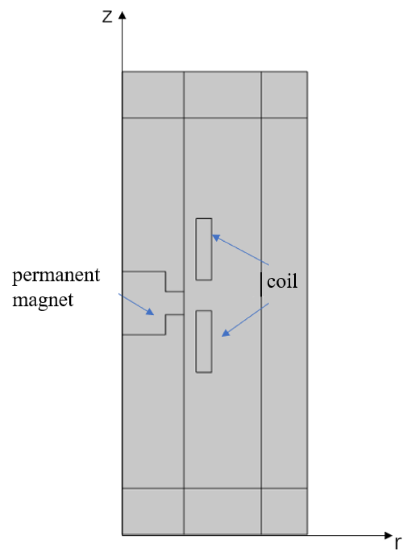
This section primarily examines the relationship between the energy collection efficiency of the generator and the spring stiffness, as well as the coil position, through simulation methods, offering insight for the design phase. In this study, COMSOL Multiphysics 5.6 is utilized to predominantly simulate the aforementioned force–electric–magnetic coupling model. The coupling simulation involves the use of multiple software modules, including magnetic field, circuit and global differential equation modules. Given the cylindrical shape of the generator’s support and magnet, a two-dimensional axisymmetric module is employed for modeling, as depicted in Figure 3. The global differential equation module facilitates the coupling of the pickup unit and the electromagnetic unit, with the capability to integrate the influence of the spring on the magnet’s motion. The global differential equation is represented as follows:
M x ( t ) ¨ + c x ( t ) ˙ + k x ( t ) F z = F L
where M is the mass of the permanent magnet and c is the damping coefficient. Referring to the relevant literature and according to the experimental test, it is estimated that the damping ratio of the generator pickup unit system to remove the electromagnetic damping is 0.1; x ( t ) is the displacement of the permanent magnet; k is the spring stiffness; F z is the Lorentz force; and F L is the external load.
We utilized the dynamic mesh module of COMSOL software to couple the displacement x ( t ) of the permanent magnet with the displacement expression of the dynamic mesh, achieving the dynamic simulation of the permanent magnet.
Currently, permanent magnet materials widely used in industry and modern technology are classified into three categories: aluminum–nickel–cobalt, ferrite and rare earth permanent magnet materials. Among them, NdFeB permanent magnet material stands out due to its excellent magnetic properties and low price. It is gradually replacing samarium–cobalt rare earth and aluminum–nickel–cobalt permanent magnet materials. Therefore, the simulation uses NdFeB permanent magnet material of brand N 35 , which has a cylinder shape with a height of 4 mm and a radius of 3 mm . The overload applied on the magnet is equivalent to the curve shown in Figure 4, where g represents the acceleration due to gravity.
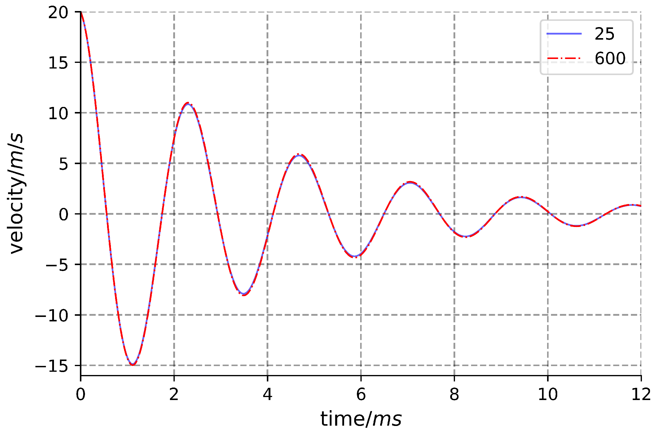
Since the number of winding coils can impact the outcomes, the influence of the Lorentz force on the magnet’s motion is initially computed within the coil’s winding range. Specifically, the 25-turn and the 600-turn coils are separately wound in the same position, as depicted in Figure 3. The simulation results indicate that the Lorentz force stemming from the coil’s winding range minimally affects the magnet’s motion, as illustrated in Figure 5. This is primarily due to the structural resistance constituting the main component of resistance during the permanent magnet’s motion, rendering the Lorentz force relatively insignificant. Consequently, the variation in the coil exerts minimal impact on the permanent magnet’s motion. Thus, the findings obtained using 25-turn coils in subsequent sections can be extrapolated to coils within the specified range of winding turns.
A two-dimensional coordinate system is established, as depicted in Figure 3, with the center of the permanent magnet serving as the coordinate origin, the radial distance as the r-axis, and the axial distance as the z-axis. The 25-turn coils are wound at specific coordinates: ( 5.3 , 6 ) , ( 5.3 , 5 ) , ( 5.3 , 4 ) , ( 5.3 , 3 ) , ( 5.3 , 2 ) , ( 5.3 , 1 ) , ( 5.3 , 0 ) , ( 5.3 , 1 ) , ( 5.3 , 2 ) , ( 5.3 , 3 ) , ( 5.3 , 4 ) , ( 5.3 , 5 ) , ( 5.3 , 6 ) . For each coil position, the proportion of work conducted by the Lorentz force contributing to the energy loss within each vibration period is calculated under different spring stiffness settings: 2 N / mm , 8 N / mm , 16 N / mm and 32 N / mm . Initially, the time-varying profile of the overall circuit power is computed. As the work performed by the Lorentz force—cutting through the magnetic induction lines—is converted into electrical energy, the integration of power over time within each cycle represents the work accomplished by the Lorentz force during that cycle. Subsequently, the total energy loss of the vibration system within each period is determined by utilizing the speed of the permanent magnet as it passes through each equilibrium position. This approach enables the calculation of the ratio between the two values.

2.2.2. Simulation Results and Analysis

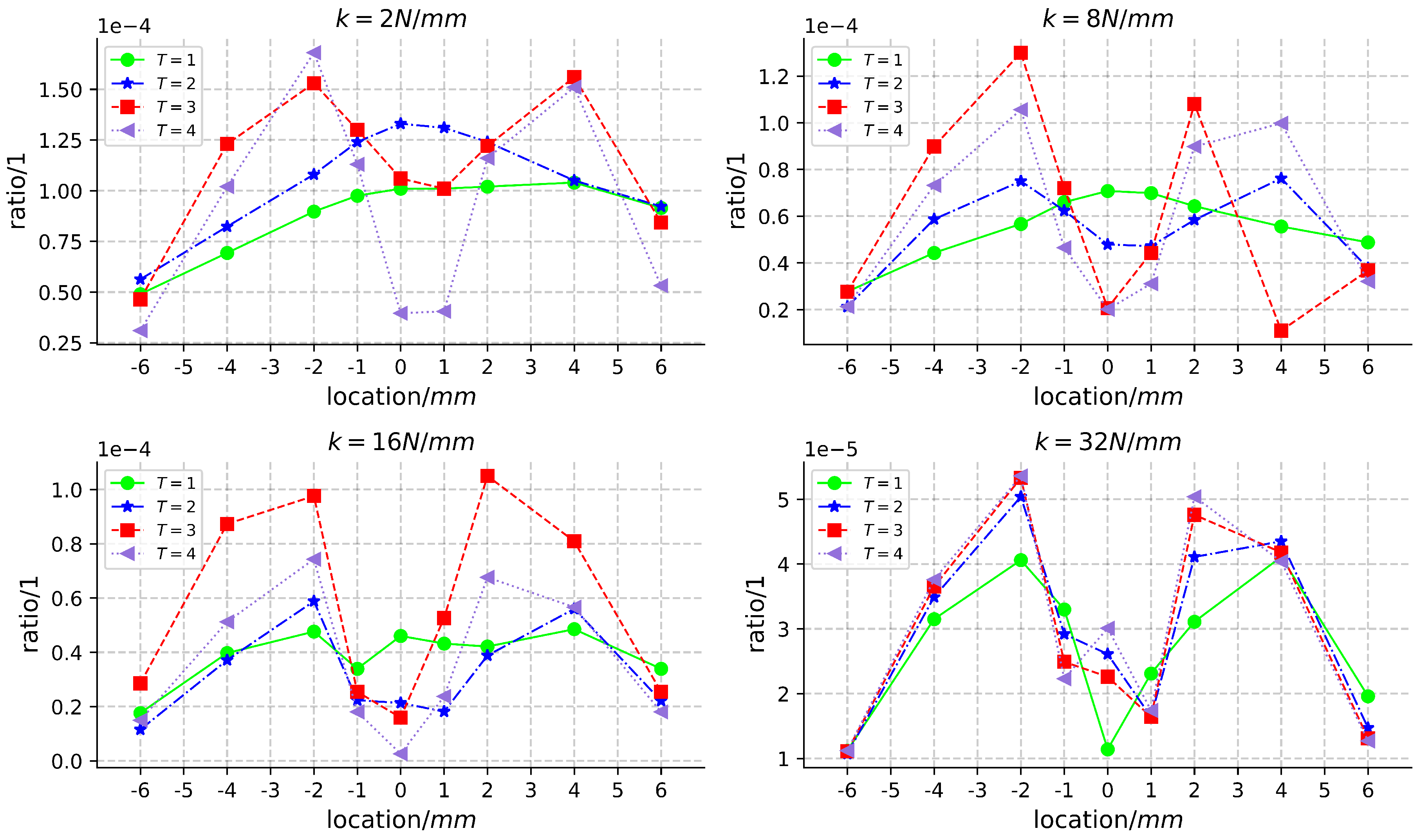
For the coils at each position, when the spring stiffness is 2 N / mm , 8 N / mm , 16 N / mm and 32 N / mm , the proportion of the work conducted by the Lorentz force in the system loss energy during the first to fourth periods are, respectively, drawn in Figure 6. The x-axis (location) represents the axial distance between the coil winding position and the initial center point of the magnet, while the y-axis (ratio) represents the calculated ratio. T is the vibration period of the permanent magnet. k is the spring stiffness. Upon observing the image, it is evident that when the coil is positioned at + 2 mm and 2 mm away from the magnet’s center, the work performed by the Lorentz force constitutes a significant proportion of the total energy loss in each cycle. Conversely, when the coil is positioned at + 6 mm and 6 mm away from the magnet’s center, the proportion of work performed by the Lorentz force in each cycle is relatively small. Notably, when the coil is in close proximity to the center position, the proportion of work performed by the Lorentz force exhibits substantial variation across different spring stiffness values and cycles.
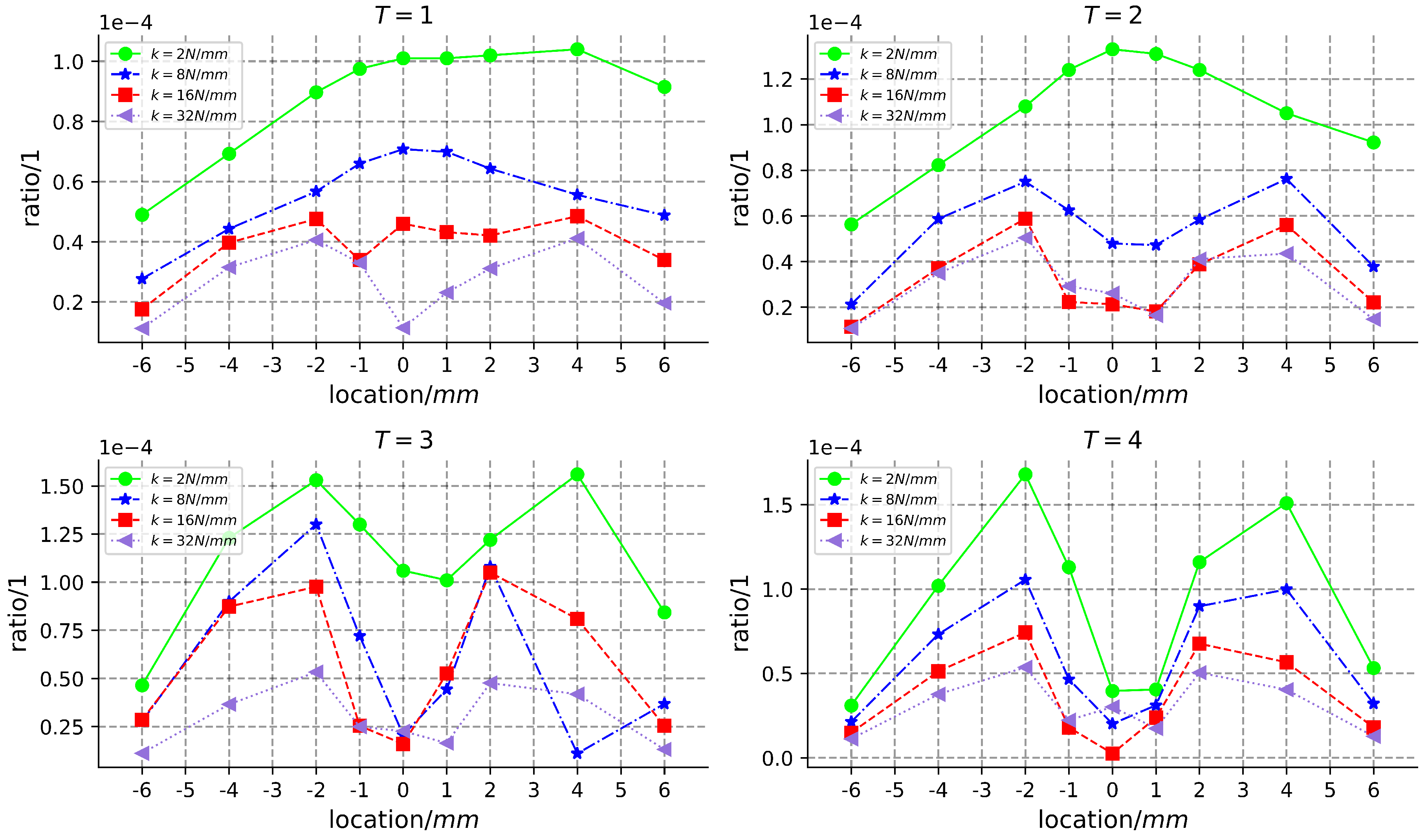
For the coils at each position, from the first to fourth periods, the proportion of the work performed by the Lorentz force in the system loss energy when the spring stiffness is 2 N / mm , 8 N / mm , 16 N / mm and 32 N / mm are, respectively, drawn in Figure 7. The x-axis (location) represents the axial distance between the coil winding position and the initial center point of the magnet. The y-axis (ratio) represents the calculated ratio. In this study, T denotes the vibration period of the permanent magnet and k represents the spring stiffness. From the diagram, it is observed that as the spring stiffness increases, the proportion of work performed by the Lorentz magnetic force in each cycle decreases. When the vibration period is short, a smaller spring stiffness results in a larger proportion of work performed by the Lorentz force closer to the center position. Conversely, with a larger spring stiffness, the proportion of work performed by the Lorentz force is greater when the coil is closer to the + 2 mm and 2 mm positions. As the number of cycles increases, regardless of the spring stiffness, the closer the coil is positioned to the + 2 mm and 2 mm positions, the greater the proportion of work performed by the Lorentz force.
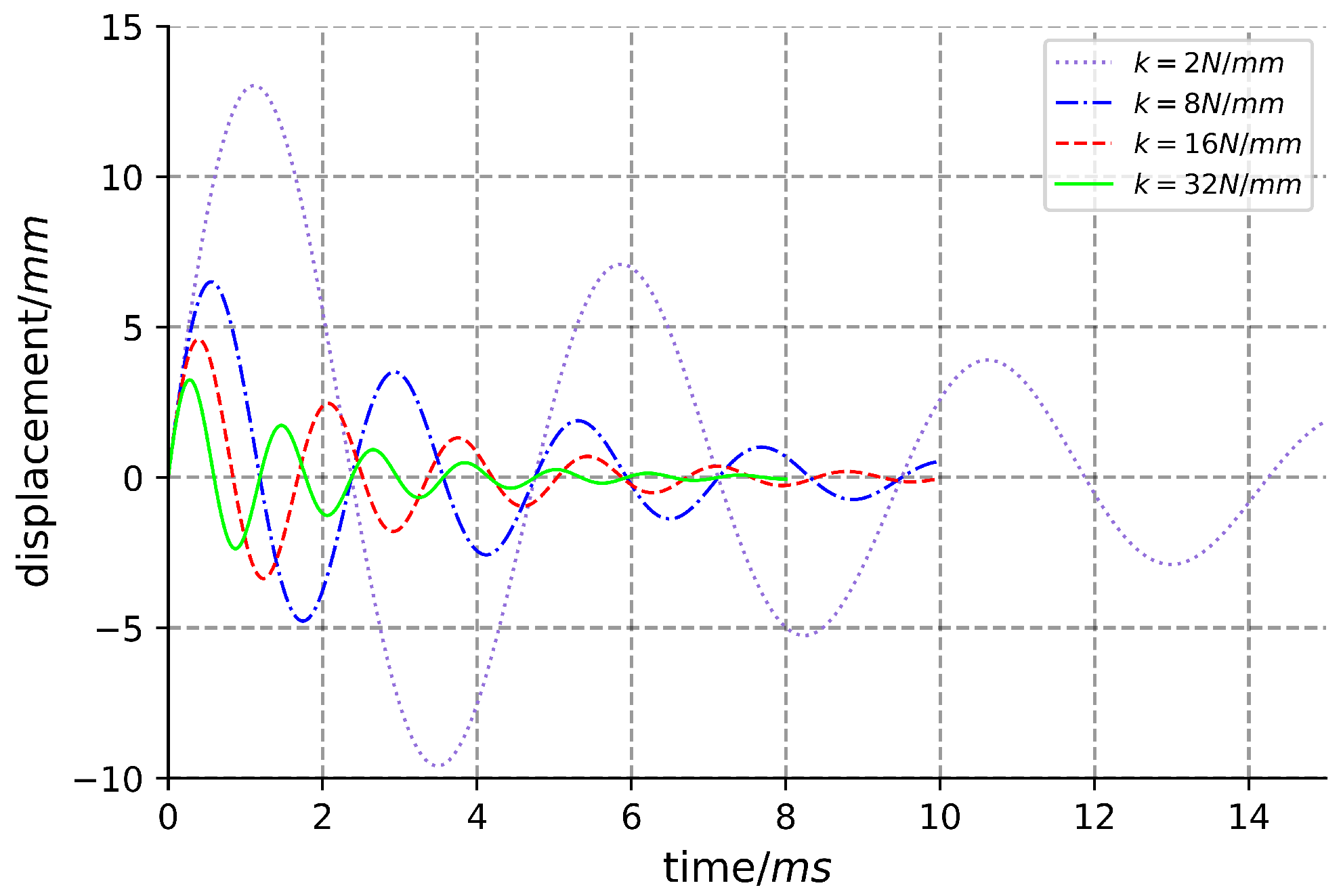
As shown in Figure 8, the displacement–time graph of the permanent magnet under different spring stiffness is presented. The height of the magnet is 4 mm . By combining the conclusions obtained from Figure 7, it can be inferred that the force–electricity conversion rate is dependent on the maximum displacement of the permanent magnet. Once the spring stiffness is determined, if the maximum displacement of the generator’s permanent magnet under external excitation exceeds the magnet’s height, the proportion of work conducted by the Lorentz force becomes greater as the coil moves closer to the center. On the other hand, if the maximum displacement of the generator’s permanent magnet under external excitation is smaller than the magnet’s height, the proportion of work conducted by the Lorentz force becomes greater as the coil moves closer to the two ends of the magnet.

2.3. Generator Design

2.3.1. Selection and Design of Permanent Magnet

Theoretical analysis indicates that permanent magnets should possess characteristics such as high density, high magnetic flux and stable performance. Additionally, due to the high impact force involved in electricity generation, the generator also requires good impact resistance and vibration capabilities. NdFeB permanent magnet materials not only exhibit excellent magnetic properties, but also have a significantly higher mechanical strength compared to other permanent magnet materials, while being cost-effective [16]. According to the requirements, an NdFeB permanent magnet with the grade of N 35 was ultimately selected. The specific performance parameters are presented in the Table 1.
The determination of permanent magnet size requires a comprehensive consideration of factors such as overall dimensions, maximum impact force and spring stiffness. Here, the overall dimensions and maximum impact force of the generator are considered as fixed values. When the size of the permanent magnet is small, the total energy and magnetic flux after impact are also small, resulting in a smaller amount of collected energy. Conversely, when the size of the permanent magnet is large, the total energy and magnetic flux after impact are larger. However, in cases where the overall dimensions are fixed, a larger permanent magnet size means a smaller range of vibration. If a stiffer spring is used, simulation analysis shows that the energy conversion rate will be low. On the other hand, if a less stiff spring is used, the limited moving space results in the spring storing much less energy than the kinetic energy of the permanent magnet. Consequently, a significant amount of energy is wasted directly, and the overall energy conversion rate remains low. Therefore, it is preferable to have a larger mass for the permanent magnet, while considering the dimensions of the overall structure. The kinetic energy of the permanent magnet after the maximum impact should ideally not exceed the upper limit of energy that the spring can store.
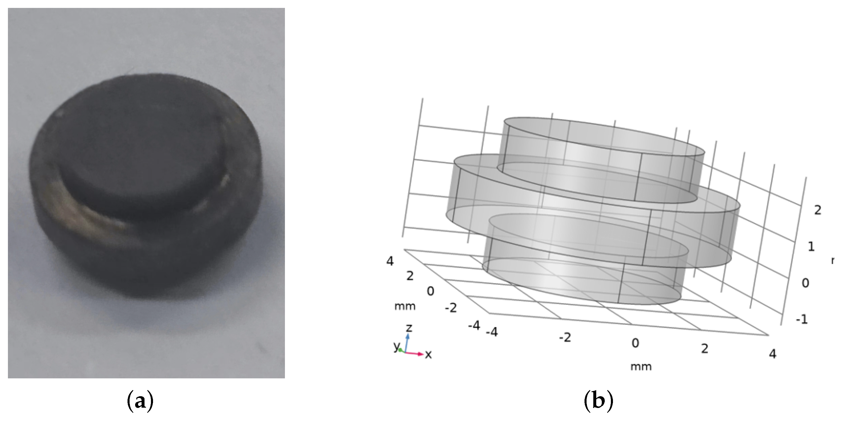
The size of this design is a cylinder with a diameter of no more than 12 mm and a height of no more than 30 mm . The maximum impact load is the overload in Figure 4. The radial direction of the cylinder needs to have a wall thickness and a winding coil space, and the maximum diameter of the permanent magnet is set to not exceed 8 mm. The length of the axial direction of the cylinder includes the wall thickness, the shortest compression length of the springs on both sides, the vibration range of the permanent magnet and the original length of the magnet. Considering the influence of spring stiffness on energy collection efficiency, it is more appropriate to select the length of the permanent magnet to be about 4 mm through simulation calculation. In order to better connect the two sides of the permanent magnet with the spring, it is designed as a magnet block, shown in Figure 9. The upper and lower parts are a cylinder with a diameter of 5.6 mm and a height of 1.3 mm , which allows the spring to be placed on it. This also increases space utilization. The middle is a cylinder with a diameter of 8 mm and a height of 1.5 mm . According to the design requirements, the size of the cylinder should have a diameter no greater than 12 mm and a height no greater than 30 mm . The maximum impact load corresponds to the overload shown in Figure 4. In the radial direction, the cylinder needs to have a wall thickness and winding coil space, while the maximum diameter of the permanent magnet should not exceed 8 mm . The length of the cylinder in the axial direction includes the wall thickness, the shortest compression length of the springs on both sides, the vibration range of the permanent magnet and the original length of the magnet. Through simulation calculations, it is recommended to choose a permanent magnet length of approximately 4 mm , taking into account the influence of spring stiffness on energy collection efficiency. To better connect the two sides of the permanent magnet with the spring, it is designed as a magnet block, as shown in Figure 9. The upper and lower parts are cylinders with a diameter of 5.6 mm and a height of 1.3 mm , which allows the spring to be placed on it. This design also increases space utilization. The middle part is a cylinder with a diameter of 8 mm and a height of 1.5 mm .

2.3.2. Design of Spring

On one hand, it is crucial to minimize the stiffness of the spring in order to ensure a high conversion rate of kinetic energy. On the other hand, the spring should also be capable of storing a larger amount of energy than the maximum electric energy of the permanent magnet. Taking into account the design and selection of permanent magnets, the total stiffness of the spring is determined to be 8 N / mm . Since the spring is distributed on both sides of the permanent magnet, the stiffness of each unilateral spring is k = 4 N / mm .
The performance and service life of the spring are significantly influenced by the choice of spring material. The spring used in the generator must possess a high elastic limit and fatigue strength to withstand impacts, necessitating a material with adequate toughness and plasticity. After careful consideration, 50CrVA has been selected as the material for the mechanical linear spring in the generator vibration pickup unit. The specific performance parameters of 50CrVA are outlined in Table 2.
According to the application environment of the spring, the maximum displacement of the spring S m a x = 8.63 mm and the maximum load F m a x = 34.52 N. Referring to the national standard of the size series of ordinary cylindrical helical springs, the middle diameter of the spring D = 6.5 mm is selected. At the same time, from the strength condition, the formula conditions can be obtained:
8 k C 3 π τ F m a x C = D d
where τ is the required shear stress of the spring wire material. Because the spring is the main component of the whole generator, it is classified as class I spring. C is the winding ratio. After calculation, d = 0.8 N / mm was selected. From the stiffness condition, it can be obtained that:
k = F m a x S m a x = G d 4 8 n D 3
where G is the shear modulus of spring wire material. The effective number of cycles n = 3.7 is calculated. According to the calculation formula:
H 0 = p n + 2 d
p = 0.5 D
b = H 0 D
where H 0 is the free length; p is pitch; b is the slenderness ratio. H 0 = 13.6 mm and b = 2.1 are calculated. Due to b < 3.7 , the stability requirement is satisfied [17].

2.3.3. Selection of Coils Position

When other conditions are the same, the coils are, respectively, wound on the support as follows:
1.
Arbitrarily select a turn of coil, ( c 0 ), to wind on the support, and then wind the other coils around ( c 0 ) to form a complete unit. Altering the position of ( c 0 ) or the position of the other coils relative to ( c 0 ) signifies a different coil winding method at varying positions. All such winding methods found in this manner are documented as set ( P 0 ). The optimal winding method within set ( P 1 ) is represented by ( S 0 ). In the ( S 0 ) winding configuration, the electric energy collected by the generator under impact load is denoted as ( W 0 ).
2.
The coils are evenly divided into two parts. Initially, the first set of coils is wound using method 1. Subsequently, a turn of coil, ( c 1 ), is selected from the second set of coils to be wound around the support or the first set of coils. Finally, the remaining coils are wound around ( c 1 ). The first and second parts of the coil are independent. Altering the position of ( c 0 ), ( c 1 ), or the position of other coils relative to ( c 0 ) or ( c 1 ) is defined as a coil-winding method at different positions. All such winding methods found in this manner are recorded as set ( P 1 ). The optimal winding method within set ( P 1 ) is denoted as ( S 1 ). In the ( S 1 ) winding mode, the electric energy collected by the generator under impact load is represented as ( W 1 ).
3.
The coils are evenly divided into four parts. All the possible winding modes, obtained by following the rules of methods 1 and 2, are recorded as the set ( P 4 ). Similarly, the coils can be divided into the maximum number of turns, and all the found winding patterns are recorded as the set ( P n ). The optimal winding method within set ( P n ) is denoted as ( S n ). In the ( S n ) winding mode, the electric energy collected by the generator under impact load is represented as ( W n ).
Based on the aforementioned winding method, the results obtained from method 1 can be replicated using method 2. This implies that ( P 1 P 2 ), and therefore, ( W 1 W 2 ). Similarly, ( W 1 W 2 W n ) can be deduced.
Although dividing the coils into more parts can lead to a better optimal position, it also increases the amount of calculation required. Simulation analysis demonstrates that as spring stiffness decreases, the optimal winding position of the coils shifts from the two ends of the magnet equilibrium position toward the middle. As a result, we divide the coils into two parts on average for this generator.
The coils are made of enameled wire with a diameter of 0.1 mm and have a total of 600 turns. Due to the large calculation amount required by the method in step 2 for finding the optimal position, we treat the 25-turn coils as a unit and show the cross-section of each unit coil in Figure 10. The method in step 2 is modified as follows: select a unit coil from the first part of the coil, find the best position in the axial direction of the generator outside the support (the z-axis direction of Figure 3) and wind the coil around the found position. Calculate the best position that can be wound around the already-wound coils and continue winding the next unit coil until all coils in the first part are completely wound on the generator. For the second part of the coils, select a unit coil to find the best position using the same method, and continue winding as before. It is worth noting that not all the coil positions found using this method are necessarily the optimal positions in P2, which is the better position. Using this method, we calculate the winding position of the designed coil through simulation, as shown in Figure 11.

2.4. Experiment

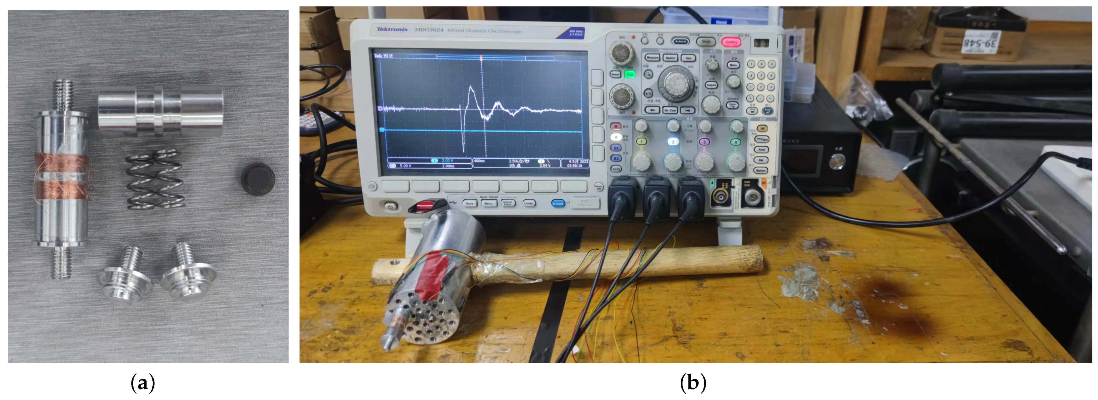
The impact magnetoelectric generator was constructed by processing and assembling the permanent magnet, mechanical linear spring, three-dimensional coil and support based on its structural design. The experimental prototype of the generator is shown in Figure 12a. Furthermore, an experimental test platform for the penetration fuze’s impact magnetoelectric generator was established, as depicted in Figure 12b. The details of the test equipment are provided in Table 3. Subsequently, a hammer test was conducted on the prototype.

3. Results and Discussion

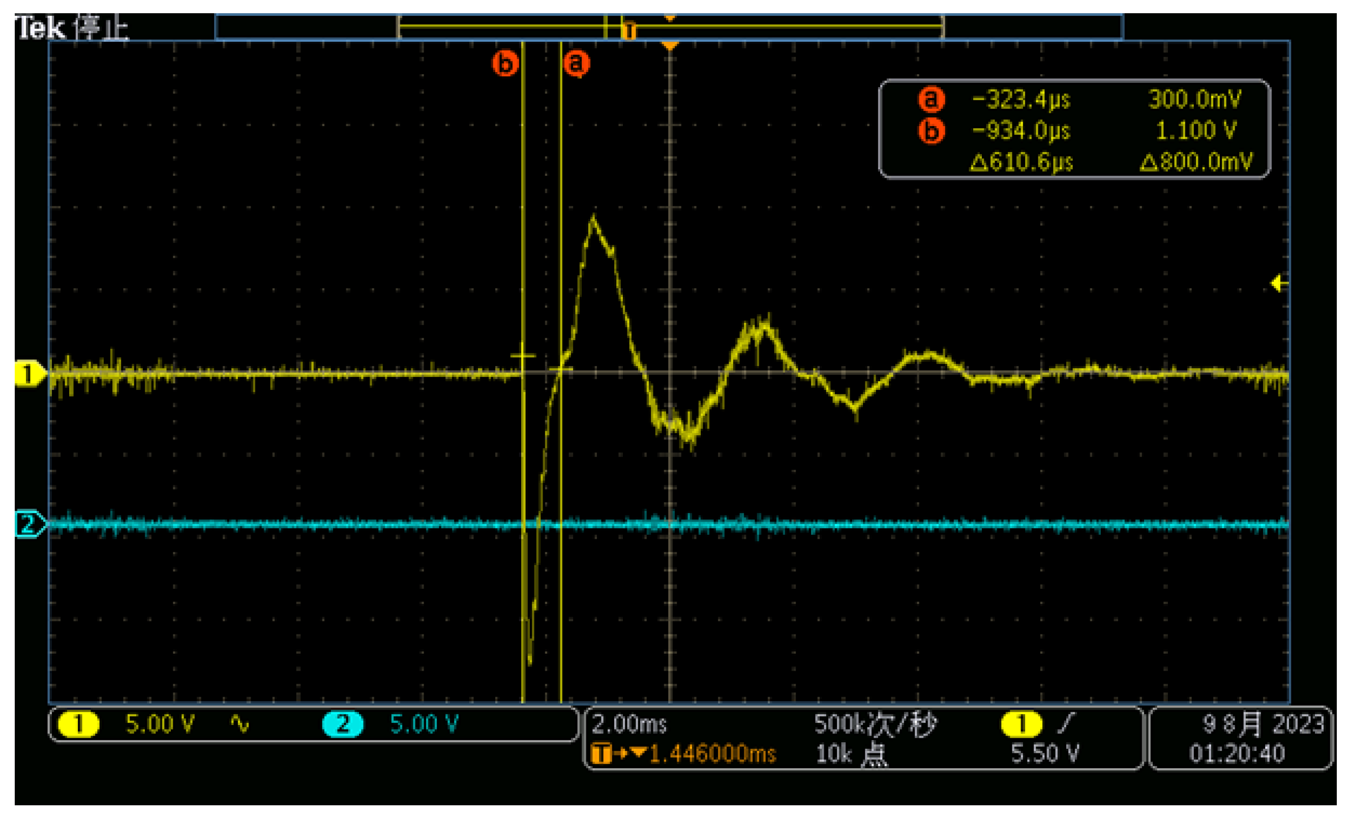
The knocking experiment was conducted on the assembled generator prototype. However, due to experimental constraints, the applied overload on the generator was limited to 15 , 382.3 g . The output of the generator prototype is illustrated in Figure 13. In the oscilloscope, Channel 1 represents the induced electromotive force generated by the generator, while Channel 2 is unconnected and indicates the influence of the environment on the test results. The damping ratio employed in this experiment corresponds to that used in the simulation analysis section.
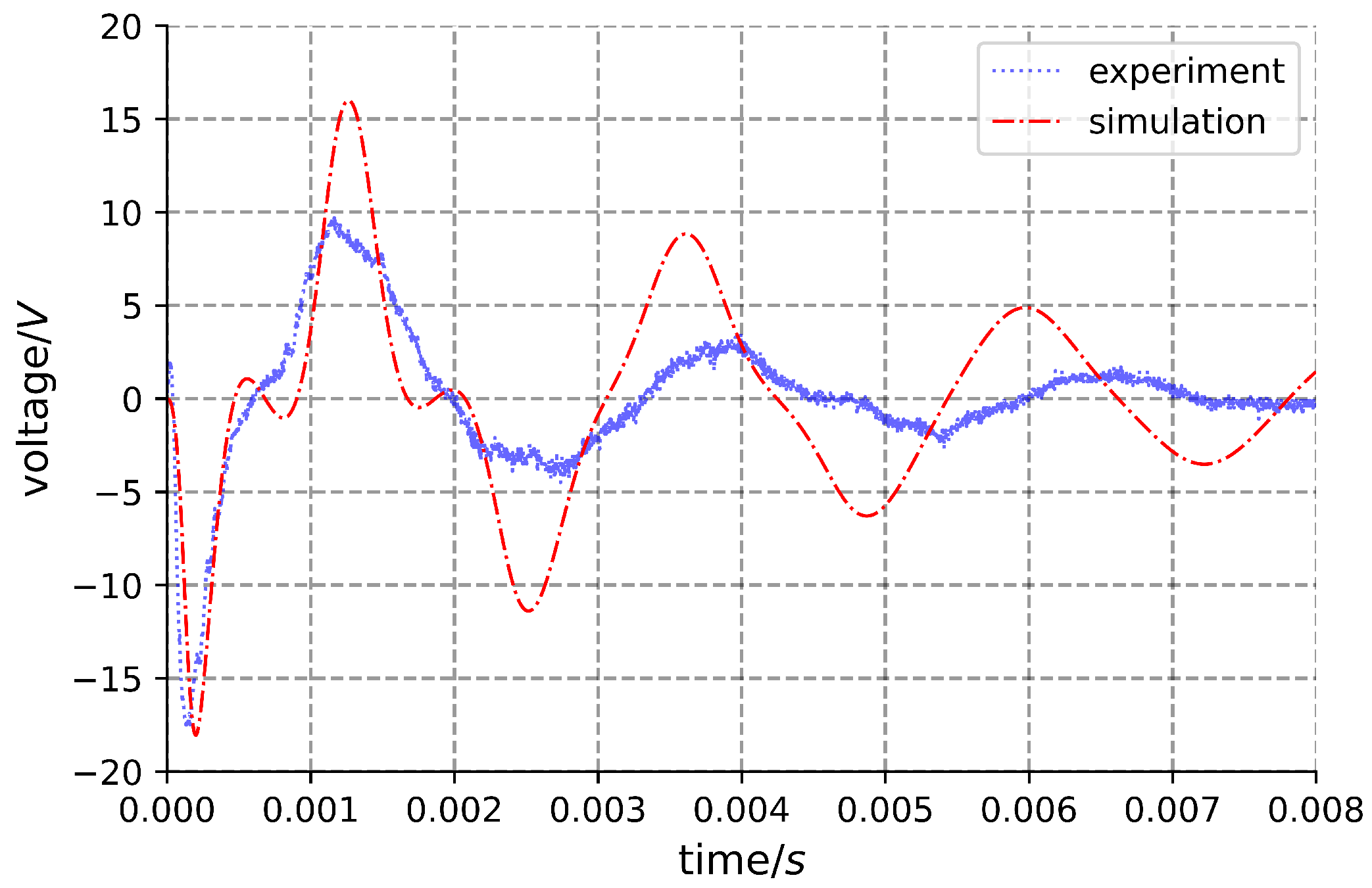
The induced electromotive force of Channel 1 is subtracted from the error caused by the environment of Channel 2, and the experimental curve such as Figure 14 is drawn. The simulation curve is obtained via COMSOL software simulation.
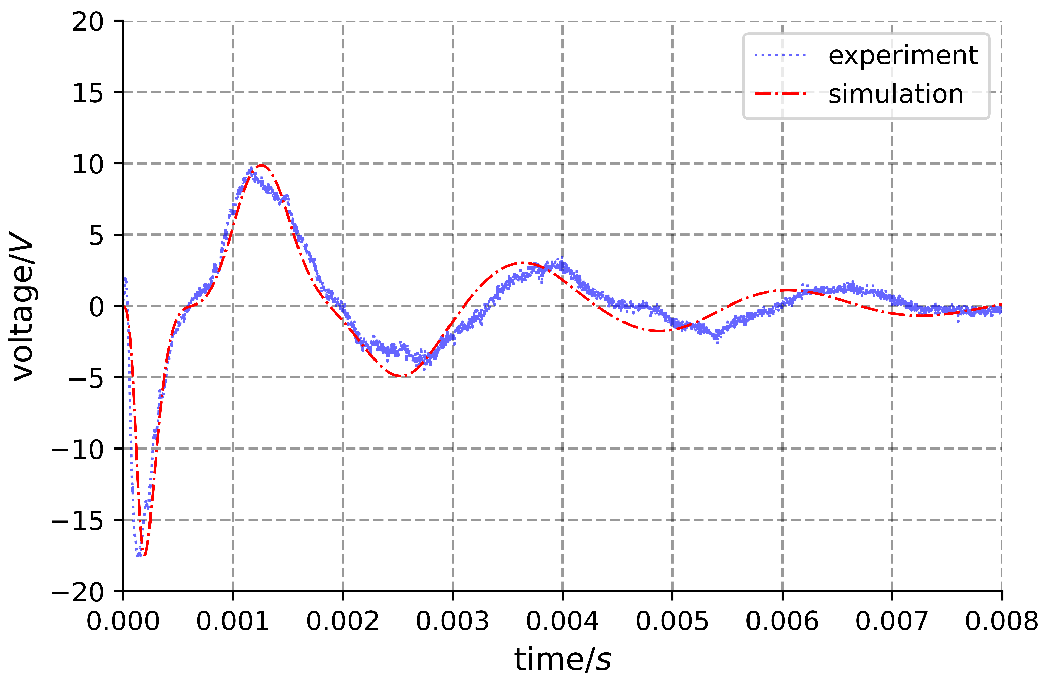
Upon comparison, it was observed that the actual maximum voltage closely approximates the simulation. During the initial cycle, the experimental data align well with the simulation; however, subsequently, the experimental values generally presented a decreasing trend compared to the theoretical values. This discrepancy may stem from the continuously changing actual damping, which tends to increase during the later stages compared to the set damping. Therefore, there is a need to enhance the set damping in the simulation. Additionally, considering that the damping of the permanent magnet varies at different positions, it is set as a function of displacement. Through calculation, the following can be derived:
ξ = | x ( t ) | 15 m m + 0.15
where ξ is the damping ratio; x ( t ) is the displacement function of permanent magnet.
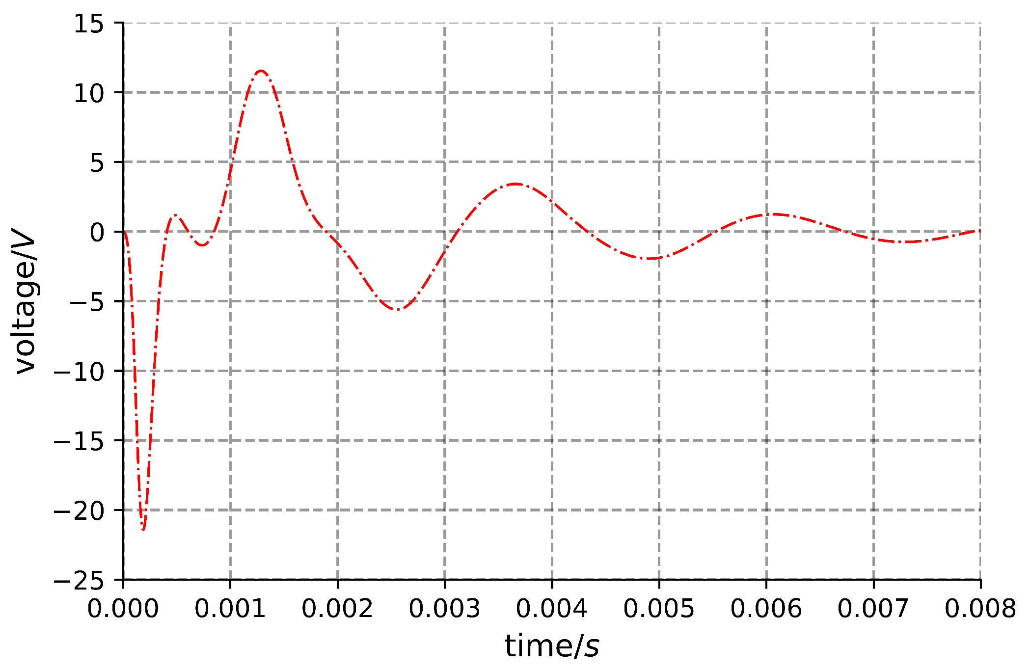
The comparison between the experimental and simulated results, after adjustment of damping, is illustrated in Figure 15. It is evident that the calculated damping aligns better with the actual scenario. Using the adjusted damping, the generator response is computed for a 20,000 g load, and the corresponding results are depicted in Figure 16. The maximum voltage attained by the generator can reach 21.5 V .

4. Conclusions

This paper presents the design of an impact-type magnetoelectric generator. The generator is a cylindrical body with a diameter not exceeding 12 mm and a height not exceeding 30 mm . It was found that the smaller the spring stiffness of this type of generator, the better its performance. For the dimensions of the generator in this study, a spring stiffness of 8 N / mm is considered optimal. If the maximum displacement of the permanent magnet is less than or close to its height, the coil winding should be positioned near the ends of the permanent magnet. Conversely, the coil winding position should be closer to the center of the permanent magnet. Finally, the approximate damping ratio of the designed generator is calculated based on experimental and simulation results. Using the adjusted damping ratio, the generator’s response under a 20,000 g load is computed, and the generator is capable of producing a voltage of up to 21.5 V .

Author Contributions

Conceptualization, B.L. (Bing Li) and S.N.; methodology, B.L. (Bingyang Li); software, B.L. (Bing Li); validation, B.L. (Bing Li), Y.S. and P.W.; formal analysis, B.L. (Bingyang Li) and S.N.; investigation, P.W.; resources, B.L.; data curation, B.L. (Bing Li) and P.W.; writing—original draft preparation, B.L. (Bing Li); writing—review and editing, B.L. (Bing Li) and Y.S.; visualization, Y.S.; supervision, S.N.; project administration, B.L. (Bingyang Li); funding acquisition, S.N. All authors have read and agreed to the published version of the manuscript.

Funding

This research is funded by 2021 Open Project Fund of Science and Technology on Electronmechincal Dynamic Control Laboratory, China (212CJFQT20220018). It is also sponsored by Beijing Nova Program (20230484287).

Data Availability Statement

Data are contained within the article.

Conflicts of Interest

The authors declare no conflict of interest.

References

  1. Li, C.; Gao, S.; Niu, S.; Liu, H. Effect of High-g Shock Environment on Performances of Energy-Storage Capacitors Used in Fuse. Acta Armamentarii 2016, S2, 16–22. [Google Scholar]
  2. Ronghua, H.; Ya, Z.; Bo, L.; Yunluan, H.; Pan, G. Parametric Variation and Failure Analysis of Military Capacitors under High Overload. Electron. Prod. Reliab. Environ. Test. 2010, 28, 24–26. [Google Scholar] [CrossRef]
  3. Zhao, Z.; Ding, X.; Liu, F.; Yang, Z. Structural Design and Simulation of Micro Electromagnetic Vibration Energy Harvester. Trans. China Electrotech. Soc. 2012, 27, 255–260. [Google Scholar] [CrossRef]
  4. Prajwal, K.T.; Manickavasagam, K.; Suresh, R. A review on vibration energy harvesting technologies: Analysis and technologies. Eur. Phys. J. Spec. Top. 2022, 231, 1359–1371. [Google Scholar] [CrossRef]
  5. Li, M. Research on an Impact-Based Magnetoelectric Generator for Penetration Fuze. Master’s Dissertation, Beijing Institute of Technology, Beijing, China, 2021. [Google Scholar] [CrossRef]
  6. Dai, X.; Wen, Y.; Li, P.; Yang, J.; Jiang, X. Vibration energy harvester based on magnetoelectric transducer. Acta Phys. Sin. 2010, 59, 2137–2146. [Google Scholar] [CrossRef]
  7. Williams, C.B.; Yates, R.B. Analysis of a micro-electric generator for microsystems. Sens. Actuators A Phys. 1996, 52, 8–11. [Google Scholar] [CrossRef]
  8. Liu, H.; Dong, W.; Chang, Y.; Gao, Y.; Li, W. Working characteristics of a magnetostrictive vibration energy harvester for rotating car wheels. Rev. Sci. Instrum. 2022, 93, 055001-1–055001-16. [Google Scholar] [CrossRef] [PubMed]
  9. Moradian, K.; Sheikholeslami, T.F.; Raghebi, M. Investigation of a spherical pendulum electromagnetic generator for harvesting energy from environmental vibrations and optimization using response surface methodology. Energy Convers. Manag. 2022, 266, 115824.1–115824.10. [Google Scholar] [CrossRef]
  10. Pathan, F.R. Kinetic Energy Harvesting from Human Hand Movement by Mounting micro Electromagnetic Generator. In Proceedings of the 2nd International Conference on Electrical Engineering and Green Energy (CEEGE 2019), Rome, Italy, 28–30 June 2019; EDP Sciences: Les Ulis, France, 2019; pp. 80–83. [Google Scholar] [CrossRef]
  11. Zhao, X.; Cai, J.; Guo, Y.; Li, C.; Wang, J.; Zheng, H. Modeling and experimental investigation of an AA-sized electromagnetic generator for harvesting energy from human motion. Smart Mater. Struct. 2018, 27, 085008. [Google Scholar] [CrossRef]
  12. Han, D.; Shinshi, T.; Kine, M. Energy Scavenging From Low Frequency Vibrations Through a Multi-Pole Thin Magnet and a High-Aspect-Ratio Array Coil. Int. J. Precis. Eng. Manuf.-Green Technol. 2021, 8, 139–150. [Google Scholar] [CrossRef]
  13. Oh, Y.; Sahu, M.; Hajra, S.; Padhan, A.M.; Panda, S.; Kim, H.J. Spinel ferrites (CoFe2O4): Synthesis, magnetic properties, and electromagnetic generator for vibration energy harvesting. J. Electron. Mater. 2022, 51, 1933–1939. [Google Scholar] [CrossRef]
  14. Huang, T.; Guo, B.; Zhu, J.; Ding, N.; Zhang, T.; Mao, H. Mechanism Research and Simulation of Novel Electromagnetic Recoil System. J. Ordnance Equip. Eng. 2019, 40, 109–112. [Google Scholar] [CrossRef]
  15. Xiao, J.; Wang, Y.; Wen, Q.; Zhang, B.; Chen, Z. Characteristics of Fuze Magnetic Setback Motor Safety Device. J. Detect. Control 2019, 41, 25–29,35. [Google Scholar]
  16. Jin, C. Production Applications and Development Proposals of NdFeB Permanent Magnet Materials. Foundry Technol. 2012, 33, 398–400. [Google Scholar]
  17. Yue, G.; Bao, C.; Xu, H.; Gu, L. Optimum Design of Cylindrial Helical Compression Springs. Coal Mine Mach. 2012, 33, 23–24. [Google Scholar]
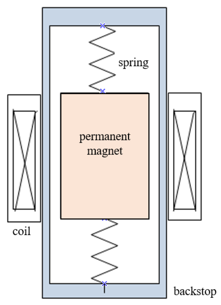
Figure 1. Structure diagram of penetration impact magnetoelectric generator.
Machines 11 01040 g001
Figure 2. Equivalent model diagram of the whole generator system.
Machines 11 01040 g002
Figure 3. Two-dimensional axisymmetric model of an impact-type magnetoelectric generator.
Machines 11 01040 g003
Figure 4. Overload curve simplified diagram.
Machines 11 01040 g004
Figure 5. Comparison diagram of magnet speed under different coils.
Machines 11 01040 g005
Figure 6. The change diagram of power ratio with coil position under the same stiffness and different periods.
Machines 11 01040 g006
Figure 7. The change diagram of power ratio with coil position under different stiffness in the same period.
Machines 11 01040 g007
Figure 8. Displacement–time graph under different stiffness.
Machines 11 01040 g008
Figure 9. (a) The physical figure of permanent magnet. (b) The modeling diagram of permanent magnet.
Machines 11 01040 g009
Figure 10. Section diagram of unit coils.
Machines 11 01040 g010
Figure 11. Coils winding position diagram.
Machines 11 01040 g011
Figure 12. (a) Compositionof magnetoelectric generator. (b) Experimental platform.
Machines 11 01040 g012
Figure 13. Magnetoelectric generator prototype voltage–time output diagram.
Machines 11 01040 g013
Figure 14. Comparison of experimental and simulation results.
Machines 11 01040 g014
Figure 15. The comparison diagram of experiment and simulation after damping adjustment.
Machines 11 01040 g015
Figure 16. Voltage diagram of generator under 20,000 g load.
Machines 11 01040 g016
Table 1. Performance parameters of NdFeB N 35 .
Capability ItemStandard Value
Remanent magnetism B r 1.20 T
Coercivity H C 900 kA/m
Maximum magnetic energy product ( B H ) m a x 279 kJ/m3
Working temperature≤80 °C
Table 2. Mechanical properties’ parameters of 50CrVA.
MaterialPermissible Shear Stress τ /MPaShear Modulus G/MPaElastic Modulus E/MPa
50CrVAClass I 600Class I 450Class I 750 78 , 000 197 , 000
Table 3. Information of the test equipment.
ManufacturerDevice ModelAnalog BandwidthRecord LengthSampling Rate
TektronixMDO3034350 MHz10 M point2.5 GS/s
Disclaimer/Publisher’s Note: The statements, opinions and data contained in all publications are solely those of the individual author(s) and contributor(s) and not of MDPI and/or the editor(s). MDPI and/or the editor(s) disclaim responsibility for any injury to people or property resulting from any ideas, methods, instructions or products referred to in the content.