
Analysis and Design of Small-Impact Magnetoelectric Generator

Abstract
:1. Introduction
2. Materials and Methods
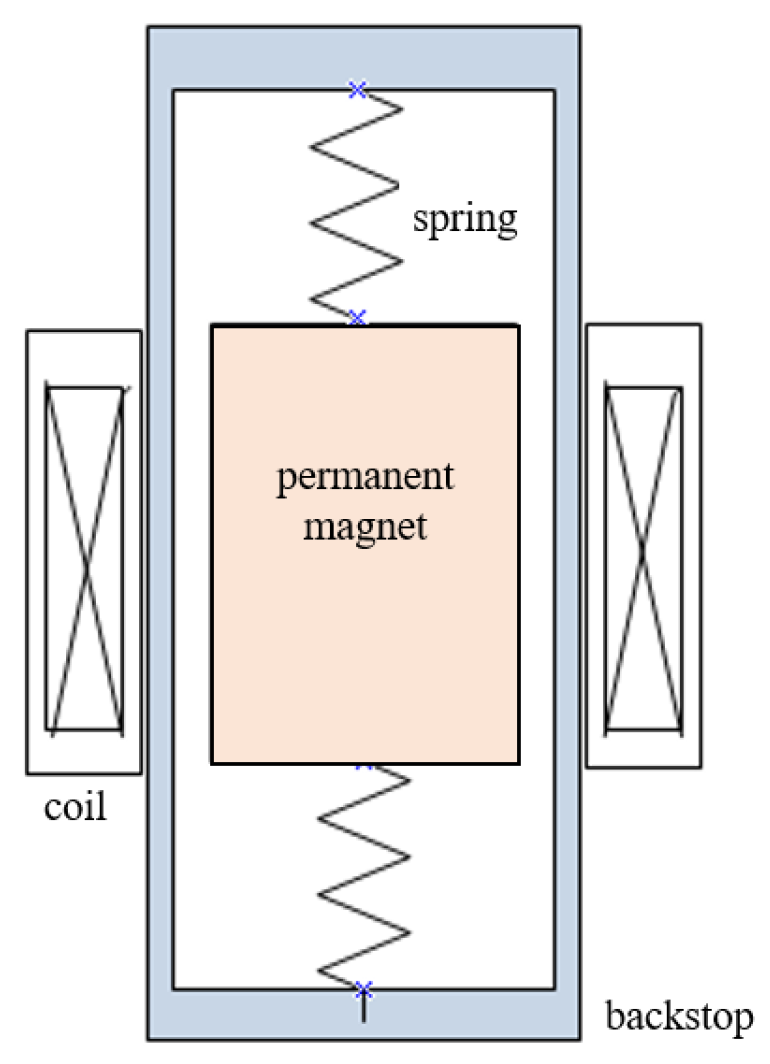
2.1. Principle of Penetration Impact Magnetoelectric Generator
2.2. Simulation Analysis
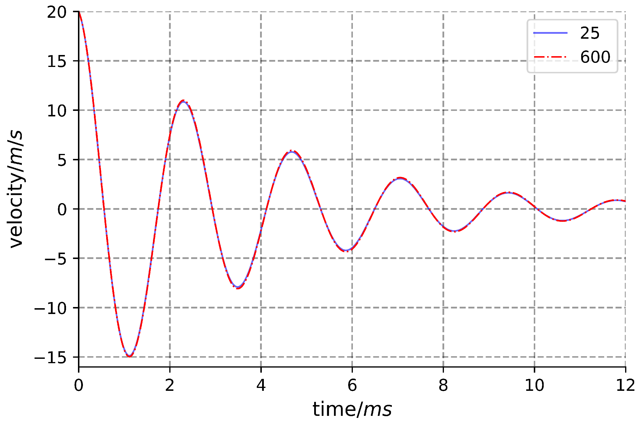
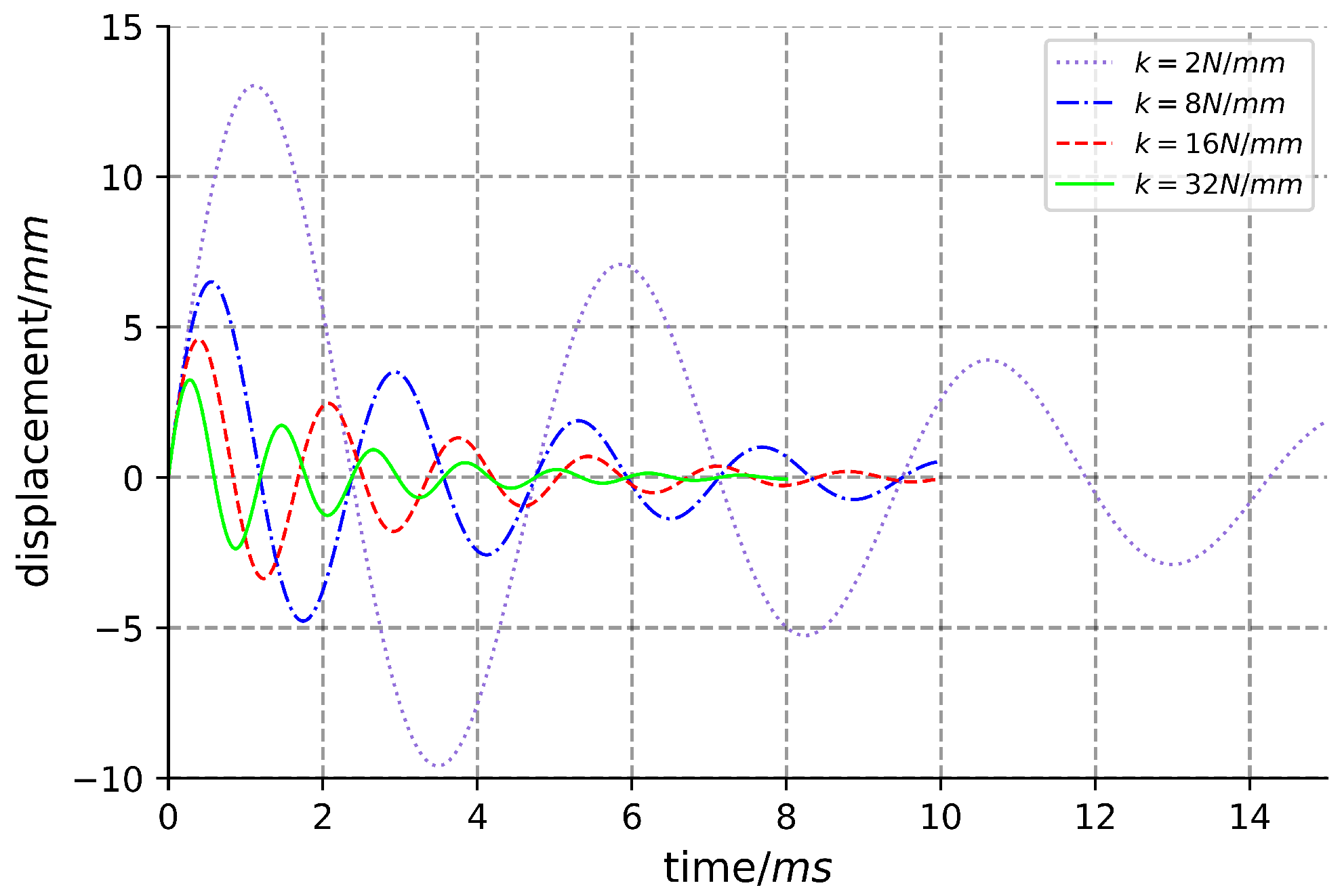
2.2.1. Simulation Model
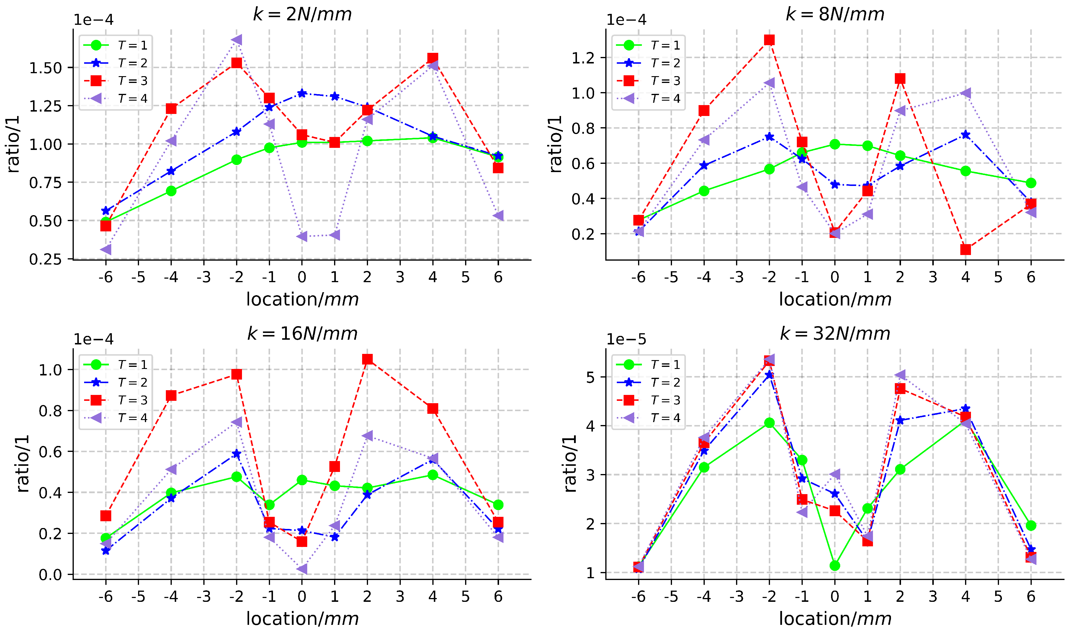
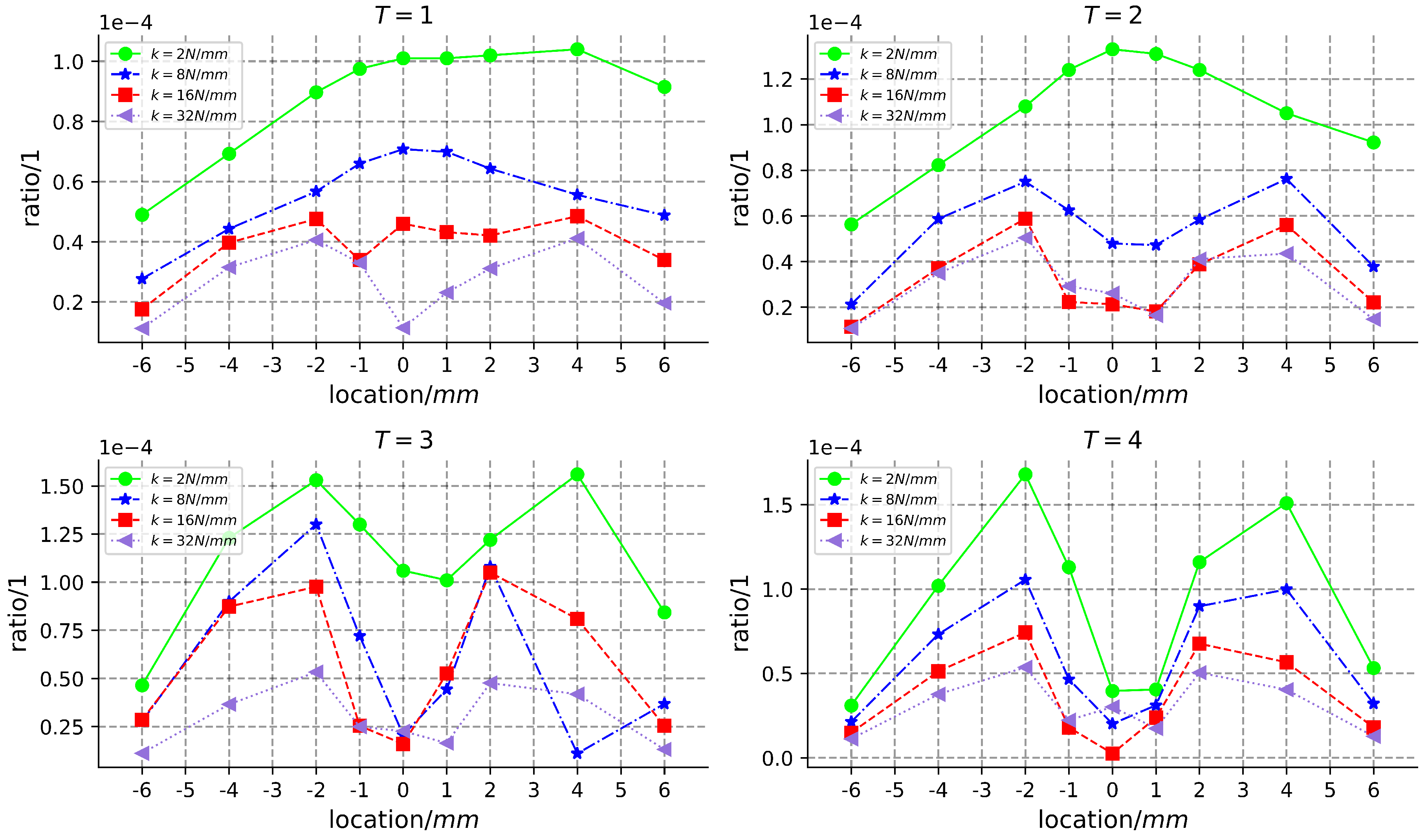
2.2.2. Simulation Results and Analysis
2.3. Generator Design
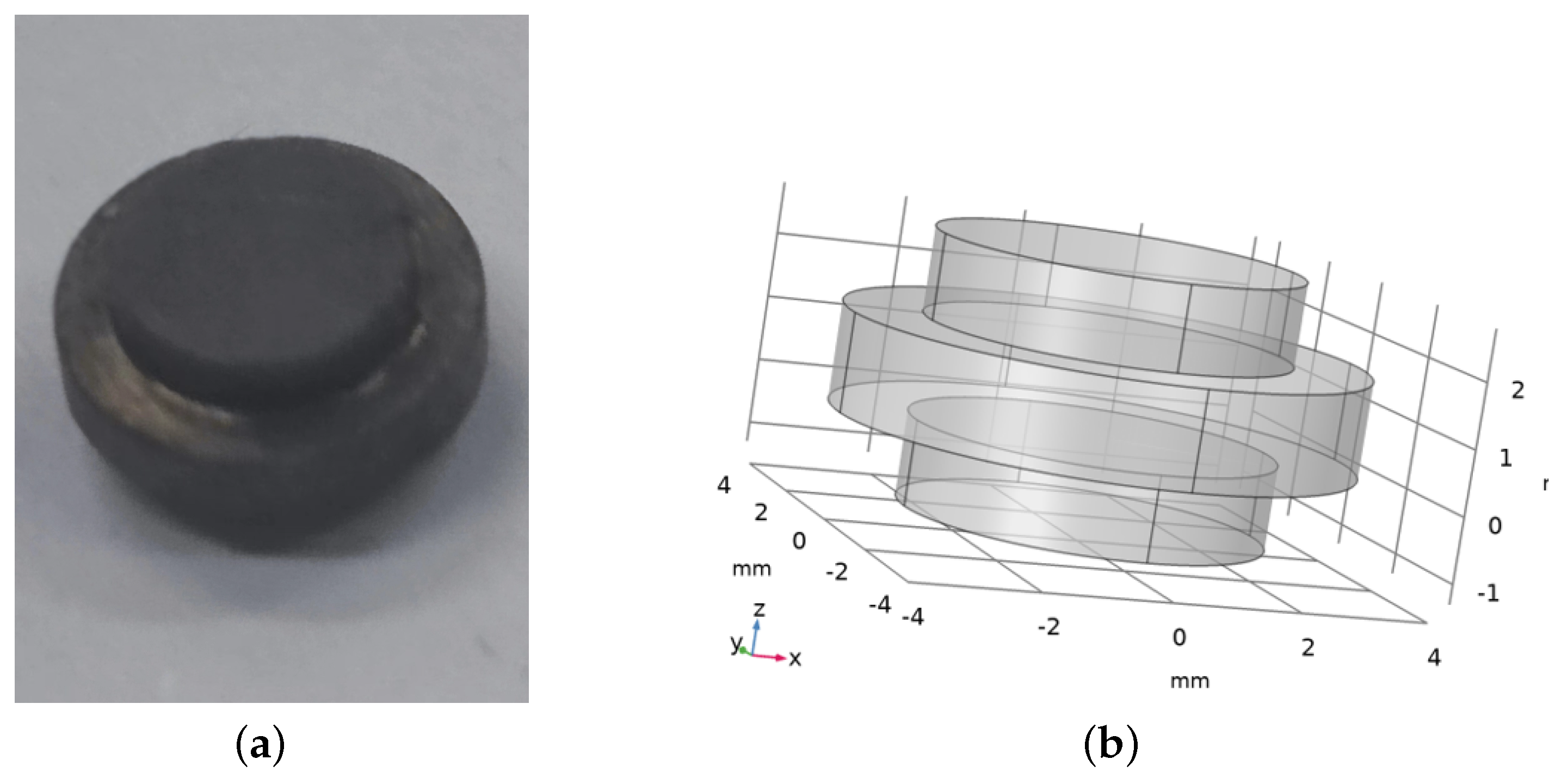
2.3.1. Selection and Design of Permanent Magnet
2.3.2. Design of Spring
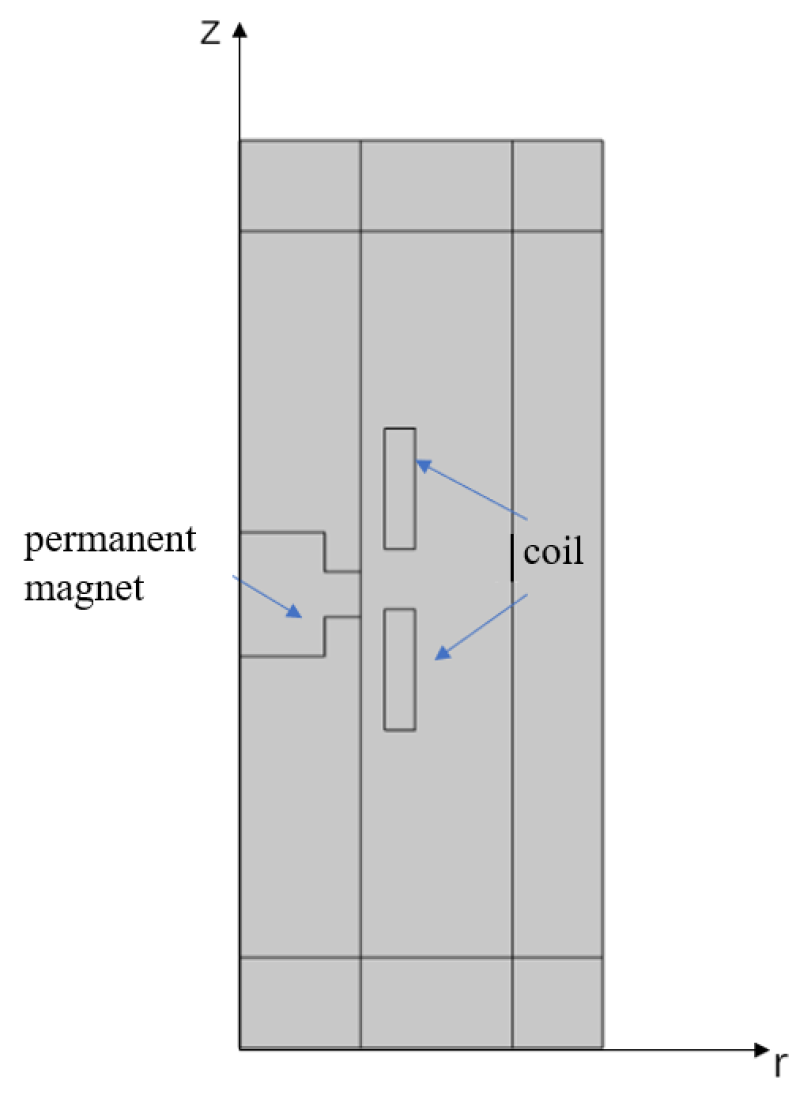
2.3.3. Selection of Coils Position
- 1.
- Arbitrarily select a turn of coil, (), to wind on the support, and then wind the other coils around () to form a complete unit. Altering the position of () or the position of the other coils relative to () signifies a different coil winding method at varying positions. All such winding methods found in this manner are documented as set (). The optimal winding method within set () is represented by (). In the () winding configuration, the electric energy collected by the generator under impact load is denoted as ().
- 2.
- The coils are evenly divided into two parts. Initially, the first set of coils is wound using method 1. Subsequently, a turn of coil, (), is selected from the second set of coils to be wound around the support or the first set of coils. Finally, the remaining coils are wound around (). The first and second parts of the coil are independent. Altering the position of (), (), or the position of other coils relative to () or () is defined as a coil-winding method at different positions. All such winding methods found in this manner are recorded as set (). The optimal winding method within set () is denoted as (). In the () winding mode, the electric energy collected by the generator under impact load is represented as ().
- 3.
- The coils are evenly divided into four parts. All the possible winding modes, obtained by following the rules of methods 1 and 2, are recorded as the set (). Similarly, the coils can be divided into the maximum number of turns, and all the found winding patterns are recorded as the set (). The optimal winding method within set () is denoted as (). In the () winding mode, the electric energy collected by the generator under impact load is represented as ().
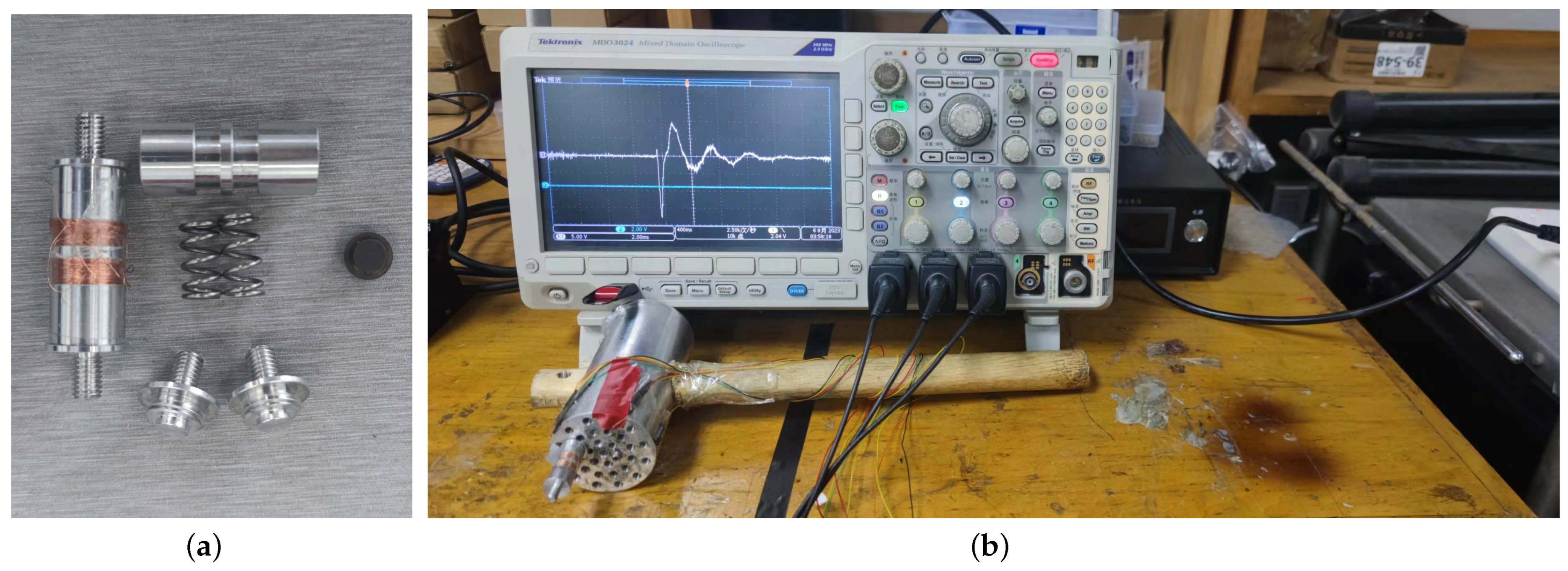
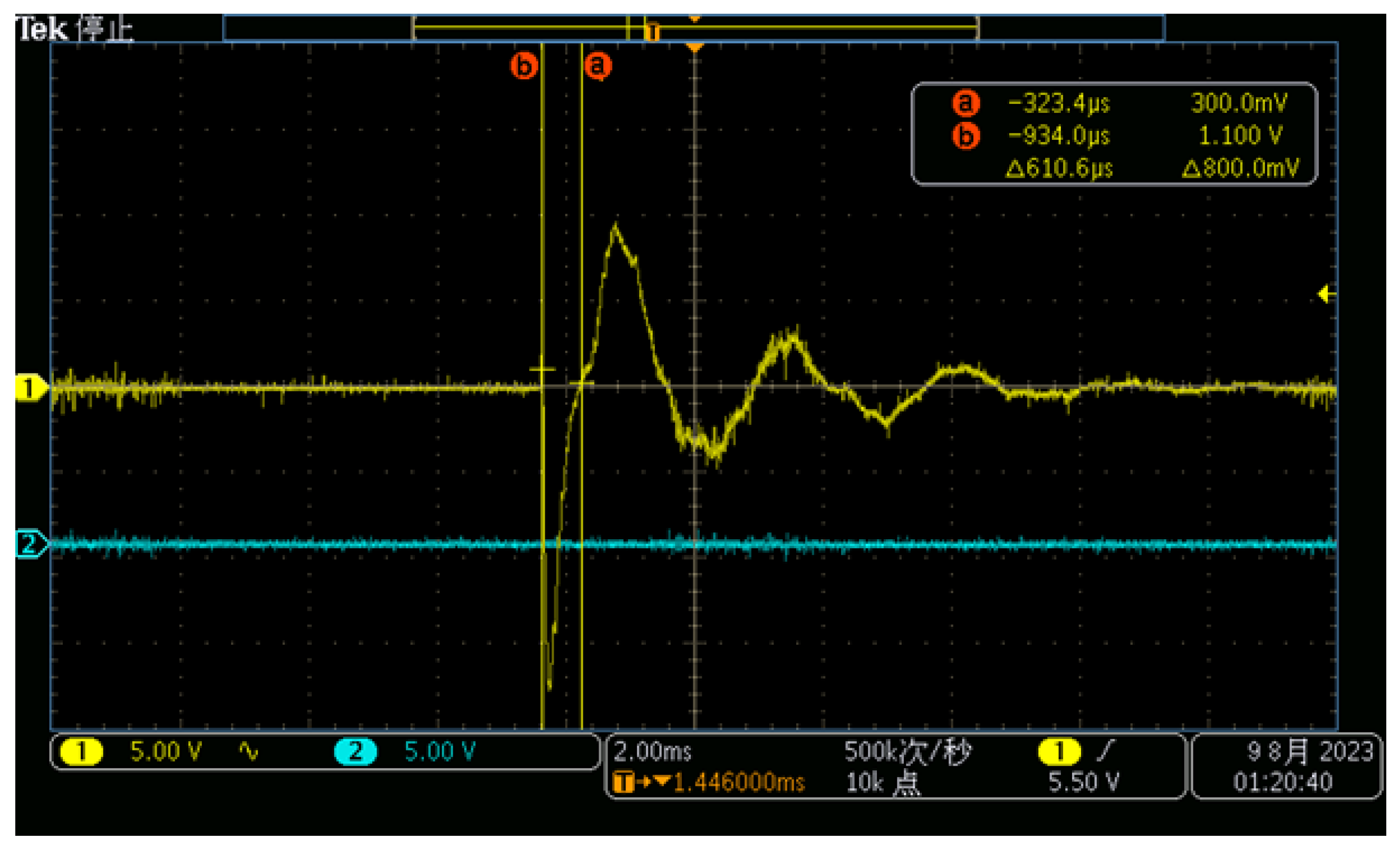
2.4. Experiment
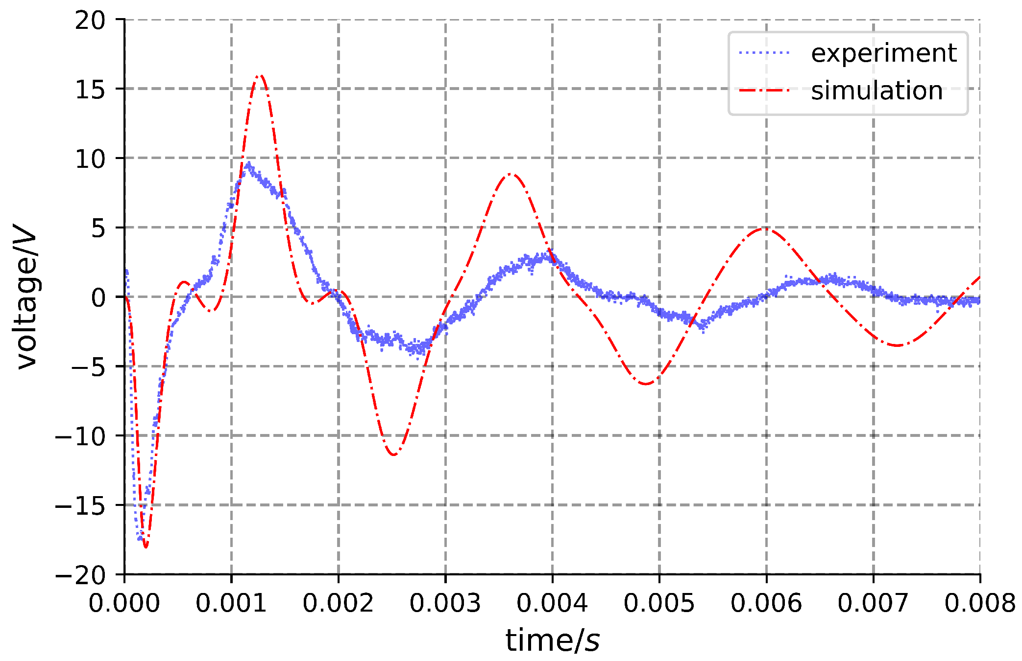
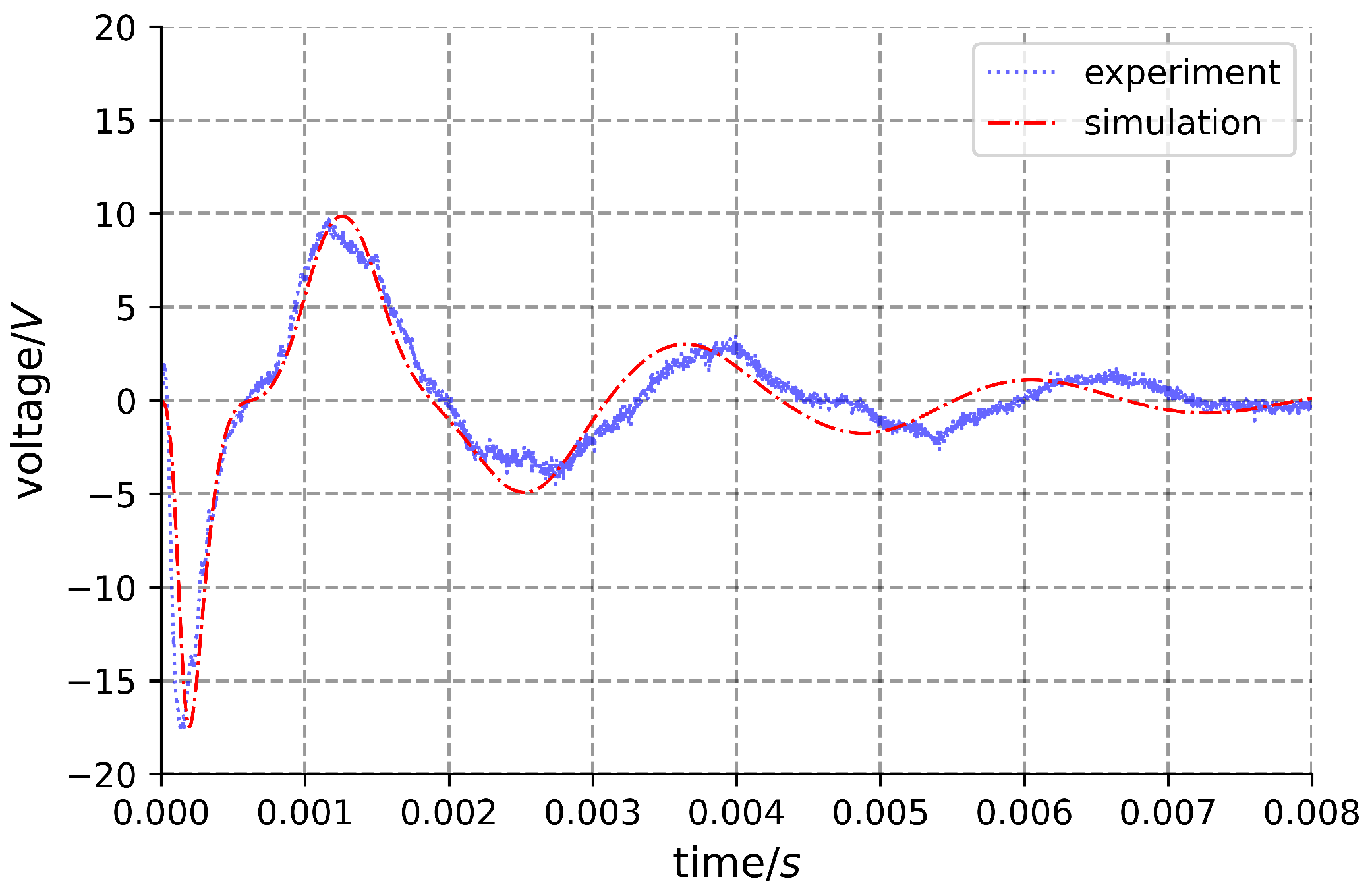
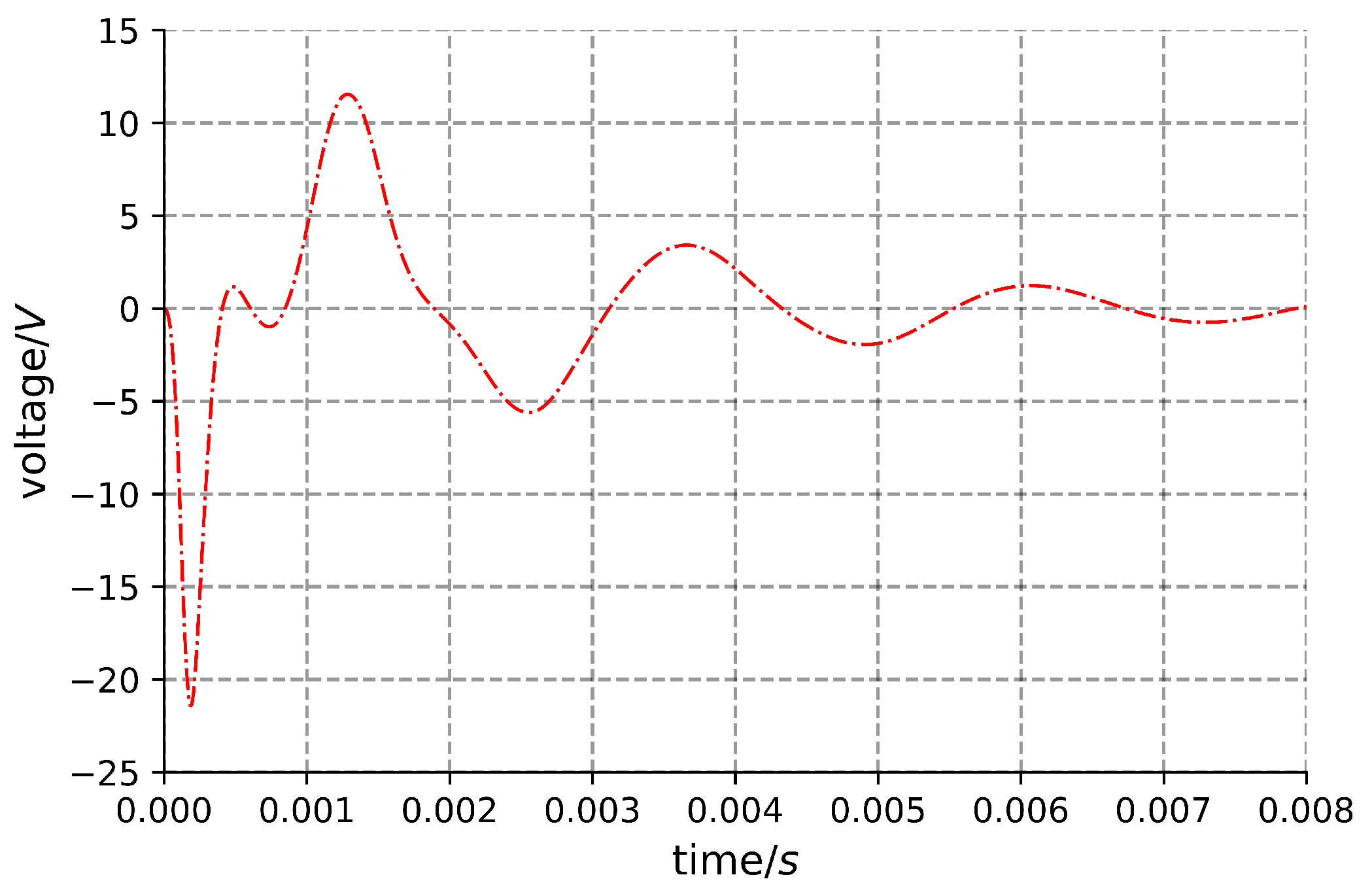
3. Results and Discussion
4. Conclusions
Author Contributions
Funding
Data Availability Statement
Conflicts of Interest
References
- Li, C.; Gao, S.; Niu, S.; Liu, H. Effect of High-g Shock Environment on Performances of Energy-Storage Capacitors Used in Fuse. Acta Armamentarii 2016, S2, 16–22. [Google Scholar]
- Ronghua, H.; Ya, Z.; Bo, L.; Yunluan, H.; Pan, G. Parametric Variation and Failure Analysis of Military Capacitors under High Overload. Electron. Prod. Reliab. Environ. Test. 2010, 28, 24–26. [Google Scholar] [CrossRef]
- Zhao, Z.; Ding, X.; Liu, F.; Yang, Z. Structural Design and Simulation of Micro Electromagnetic Vibration Energy Harvester. Trans. China Electrotech. Soc. 2012, 27, 255–260. [Google Scholar] [CrossRef]
- Prajwal, K.T.; Manickavasagam, K.; Suresh, R. A review on vibration energy harvesting technologies: Analysis and technologies. Eur. Phys. J. Spec. Top. 2022, 231, 1359–1371. [Google Scholar] [CrossRef]
- Li, M. Research on an Impact-Based Magnetoelectric Generator for Penetration Fuze. Master’s Dissertation, Beijing Institute of Technology, Beijing, China, 2021. [Google Scholar] [CrossRef]
- Dai, X.; Wen, Y.; Li, P.; Yang, J.; Jiang, X. Vibration energy harvester based on magnetoelectric transducer. Acta Phys. Sin. 2010, 59, 2137–2146. [Google Scholar] [CrossRef]
- Williams, C.B.; Yates, R.B. Analysis of a micro-electric generator for microsystems. Sens. Actuators A Phys. 1996, 52, 8–11. [Google Scholar] [CrossRef]
- Liu, H.; Dong, W.; Chang, Y.; Gao, Y.; Li, W. Working characteristics of a magnetostrictive vibration energy harvester for rotating car wheels. Rev. Sci. Instrum. 2022, 93, 055001-1–055001-16. [Google Scholar] [CrossRef] [PubMed]
- Moradian, K.; Sheikholeslami, T.F.; Raghebi, M. Investigation of a spherical pendulum electromagnetic generator for harvesting energy from environmental vibrations and optimization using response surface methodology. Energy Convers. Manag. 2022, 266, 115824.1–115824.10. [Google Scholar] [CrossRef]
- Pathan, F.R. Kinetic Energy Harvesting from Human Hand Movement by Mounting micro Electromagnetic Generator. In Proceedings of the 2nd International Conference on Electrical Engineering and Green Energy (CEEGE 2019), Rome, Italy, 28–30 June 2019; EDP Sciences: Les Ulis, France, 2019; pp. 80–83. [Google Scholar] [CrossRef]
- Zhao, X.; Cai, J.; Guo, Y.; Li, C.; Wang, J.; Zheng, H. Modeling and experimental investigation of an AA-sized electromagnetic generator for harvesting energy from human motion. Smart Mater. Struct. 2018, 27, 085008. [Google Scholar] [CrossRef]
- Han, D.; Shinshi, T.; Kine, M. Energy Scavenging From Low Frequency Vibrations Through a Multi-Pole Thin Magnet and a High-Aspect-Ratio Array Coil. Int. J. Precis. Eng. Manuf.-Green Technol. 2021, 8, 139–150. [Google Scholar] [CrossRef]
- Oh, Y.; Sahu, M.; Hajra, S.; Padhan, A.M.; Panda, S.; Kim, H.J. Spinel ferrites (CoFe2O4): Synthesis, magnetic properties, and electromagnetic generator for vibration energy harvesting. J. Electron. Mater. 2022, 51, 1933–1939. [Google Scholar] [CrossRef]
- Huang, T.; Guo, B.; Zhu, J.; Ding, N.; Zhang, T.; Mao, H. Mechanism Research and Simulation of Novel Electromagnetic Recoil System. J. Ordnance Equip. Eng. 2019, 40, 109–112. [Google Scholar] [CrossRef]
- Xiao, J.; Wang, Y.; Wen, Q.; Zhang, B.; Chen, Z. Characteristics of Fuze Magnetic Setback Motor Safety Device. J. Detect. Control 2019, 41, 25–29,35. [Google Scholar]
- Jin, C. Production Applications and Development Proposals of NdFeB Permanent Magnet Materials. Foundry Technol. 2012, 33, 398–400. [Google Scholar]
- Yue, G.; Bao, C.; Xu, H.; Gu, L. Optimum Design of Cylindrial Helical Compression Springs. Coal Mine Mach. 2012, 33, 23–24. [Google Scholar]


| Capability Item | Standard Value |
|---|---|
| Remanent magnetism | T |
| Coercivity | 900 kA/m |
| Maximum magnetic energy product | 279 kJ/m3 |
| Working temperature | ≤80 °C |
| Material | Permissible Shear Stress /MPa | Shear Modulus G/MPa | Elastic Modulus E/MPa | ||
|---|---|---|---|---|---|
| 50CrVA | Class I 600 | Class I 450 | Class I 750 | ||
| Manufacturer | Device Model | Analog Bandwidth | Record Length | Sampling Rate |
|---|---|---|---|---|
| Tektronix | MDO3034 | 350 MHz | 10 M point | 2.5 GS/s |
Disclaimer/Publisher’s Note: The statements, opinions and data contained in all publications are solely those of the individual author(s) and contributor(s) and not of MDPI and/or the editor(s). MDPI and/or the editor(s) disclaim responsibility for any injury to people or property resulting from any ideas, methods, instructions or products referred to in the content. |
© 2023 by the authors. Licensee MDPI, Basel, Switzerland. This article is an open access article distributed under the terms and conditions of the Creative Commons Attribution (CC BY) license (https://creativecommons.org/licenses/by/4.0/).
Share and Cite
Niu, S.; Li, B.; Li, B.; Wang, P.; Song, Y. Analysis and Design of Small-Impact Magnetoelectric Generator. Machines 2023, 11, 1040. https://doi.org/10.3390/machines11121040
Niu S, Li B, Li B, Wang P, Song Y. Analysis and Design of Small-Impact Magnetoelectric Generator. Machines. 2023; 11(12):1040. https://doi.org/10.3390/machines11121040
Chicago/Turabian StyleNiu, Shaohua, Bing Li, Bingyang Li, Pengfei Wang, and Yuxi Song. 2023. "Analysis and Design of Small-Impact Magnetoelectric Generator" Machines 11, no. 12: 1040. https://doi.org/10.3390/machines11121040