Article

Effects of Matching between the Inducer and the Impeller of a Centrifugal Pump on Its Cavitation Performance

1
School of Energy and Power Engineering, Xi’an Jiaotong University, Xi’an 710049, China
2
Xi’an Pump and Valve Plant Co., Ltd., Xi’an 710025, China
*
Author to whom correspondence should be addressed.
Machines 2023, 11(2), 142; https://doi.org/10.3390/machines11020142
Submission received: 30 November 2022 / Revised: 9 January 2023 / Accepted: 16 January 2023 / Published: 20 January 2023
(This article belongs to the Special Issue Selected Papers from CITC2022)

Abstract

:
The inducer is often used to prevent cavitation in a centrifugal pump. However, it may lead to deterioration of the cavitation performance of the pump when poorly matched with the impeller. Numerical simulations are employed to study the effects of the matching, specifically, the axial space and the circumferential deflection between the inducer and the impeller, on the cavitation performance. The results show that the inducer destroys the rotational symmetry of the velocity distribution at the inlet of the impeller, resulting in the influence of cavitation on the part of the channels in advance, which explains why the inducer cannot improve the cavitation performance even though it improves the inlet energy of the impeller. On the basis of not changing the geometric shape of the inducer and the impeller, the suction-specific speed is increased by nearly 300 by only adjusting the axial space and by nearly 100 by only adjusting the circumferential deflection. The cavitation performance is better with a larger axial space. There is an optimal value of the circumferential deflection at which the pump works at the best cavitation performance. The effect of the axial space on the overall cavitation performance is more significant than that of the circumferential deflection. The results provide a useful reference for the design and installation of a centrifugal pump inducer.

1. Introduction

In recent years, with the rapid development of aviation and the petrochemical industry, the requirements for the cavitation performance of centrifugal pumps have been continuously improved. A large number of scholars have carried out research on the cavitation phenomenon.
The influence of flow conditions on cavitation is one of the important directions of investigation. Ge Mingming et al. first studied the influence of temperature on hydrodynamic erosion dynamics in a closed-loop cavitation tunnel with a small-scale Venturi tube section and quantitatively compared cavitation dynamics and structure development through an image processing method [1]. Subsequently, Ge Mingming et al. studied the influence of temperature on cavitation intensity and dynamics and suggested that the temperature of the water should be avoided at 55 °C to 60 °C in practical applications [2]. Fan Yading conducted numerical studies at different inlet temperatures and rotational speeds to predict the influence of thermodynamic effects on inducer cavitation and pressure pulsation in blade channels [3].
The development of cavitation models also means numerical simulations are becoming an important method for studying cavitation. H. Kim made the first attempt to formally introduce the growth rate of hot gas bubbles into the calculation of actual cavitation flows with free flow velocity and suggested that the assumption of the balance of steam and liquid velocity might be a potential source of error [4]. By analyzing the results of different cavitation models in steady simulation, Hou Xiayi et al. put forward suggestions for the use of cavitation models [5]. In order to reduce the influence of empirical parameters in the Zwart cavitation model, Hu Jun et al. effectively reduced the influence of bubble radius and nucleus volume fraction on the results by introducing local flow characteristics [6]. Zhang Guangjian et al. developed a fast imaging technique for measuring the internal flow field of non-transparent cavitation by utilizing the high penetration and pulse characteristics of synchrotron radiation X-rays. They completed the experimental verification of the Reboud-modified empirical model [7].
Adding a Pre-impeller inducer is one of the important techniques to improve the cavitation performance of centrifugal pumps [8]. Many scholars at home and abroad have completed a great deal of research on the structure of the inducer and the cavitation in the inducer. Sankar L. Saha et al. found that a J-shaped groove structure could control the instability caused by eddy currents [9]. Benoit Pouffary et al. designed codes to consider cavitation models based on homogeneous gasification methods and investigated the mechanisms leading to the development of flow instability [10]. Cui Baolin et al. obtained the velocity and pressure field distribution law in the induced rotation channel [11]. N. Qiu et al. discussed the relationship between cavity length and head breakdown in the inducer [12]. Guo et al. carried out a numerical simulation of cavitation and an experimental study on cavitation characteristics of a full flow channel of a centrifugal pump under four conditions: no inducer, pre-constant pitch inducer, pre-variable pitch inducer and pre-split vane inducer, and determined the influence of different structures on cavitation performance [13]. Donghyuk Kang et al. clarified the effects of an accumulator, pipe lengths and gradients of pressure and suction performances on cavitation surge [14]. Zhang Aimin studied the influence law of inducer inlet and geometric parameters on the cavitation characteristics of a centrifugal pump, paying particular attention to the meridional wedge angle of the inducer [15]. In order to suppress cavitation caused by tip clearance leakage vortices of inducer blades, Cheng Xiaorui et al. set up annular groove structures in the upstream and downstream of inducer blades and studied the influence of the location of the annular groove on cavitation performance [16]. By adding a diversion grid, stabilizer and annular groove, Lu Xianggang explored the influence of different front-end stabilizer devices on the cavitation performance of an inducer [17]. Through numerical simulation, Wang Rui carried out multi-parameter optimization design research on geometric parameters of the inducer and impeller to improve the overall cavitation performance [18].
The classical design process of the inducer only focuses on the structure of the inducer, but more and more studies have indicated that the matching between the inducer and the impeller also requires a systematic design. When the matching between the inducer and the impeller is poor, the high anti-cavitation performance of the inducer not only cannot be adequately utilized but also may make the operation of the centrifugal pump worse [19]. Li Rennian et al. found in their research that circumferential deflection has a certain influence on pump cavitation performance [20]. Sun Qiangqiang et al. also found that circumferential deflection has an influence on pump cavitation performance and also found that axial space also has an influence on pump cavitation performance [21]. Wang Wenting et al. showed in their study that although inducer structure is an important factor affecting pump performance, matching also affects pump performance [22]. Lu Jinling et al. preliminarily discussed the problem of axial space matching through numerical simulation, but there is little research on cavitation specifically [23]. Cheng Xiaorui et al. studied the matching problem between the number of inducer blades and impeller blades and found that the number of inducer blades had a greater impact on the cavitation performance of the pump [24]. Liu He also found that matching had an impact on cavitation performance, but the focus was mainly on the matching of inducer and impeller blade numbers and the sweep angle of the inducer inlet [25].
Although axial space and circumferential deflection will directly affect the external performance and cavitation performance of centrifugal pumps, there is still a lack of in-depth research related to this. In this paper, employing numerical simulation, the centrifugal pump with the pre-inducer is taken as the research object, and the effect of the axial space and the circumferential deflection on the cavitation performance of the centrifugal pump is studied. The results show that the cavitation performance can be greatly improved by adjusting the matching between the inducer and impeller without changing the geometry of the inducer and impeller and showing how to adjust them. It will provide a reference for supplementing the matching design method of the centrifugal pump pre-inducer.

2. Methodology

2.1. Inducer and Impeller Parameters

The parameters of the centrifugal pump are flow rate Q = 610 m3/h, head H = 92 m, and rotational speed n = 2900 r/min. According to the design requirements, the cylindrical equal-pitch front inducer structure is adopted, and the main design process is as follows [26]. The inlet diameter of the inducer is:
D 1 = D 0 2 + d h 2 ,
In the formula: D0 is the equivalent diameter of the inlet, and dh is the diameter of the hub of the inducer.
D 0 = K 0 Q n 3 ,
In the formula: K0 is a constant coefficient, and Q is the volume flow. The pitch of the inducer is
P = D y π t a n β y z ,
In the formula, Dy is the diameter of the shroud, and βy is the installation angle of the inducer of the rim.
According to the calculation results, the number of inducer blades is z = 3, the blade thickness is 2 mm, the sweep angle is 120°, the diameter of the inlet and outlet is 175 mm, the pitch is 51 mm, and the axial length is 104 mm.
The impeller inlet diameter of the main impeller is D1’ = 175 mm, the outlet diameter is D2’ = 259 mm, the impeller outlet width is b2 = 44 mm, and the number of blades is Z = 7.
Pro/E software is chosen to carry out 3D modeling of the pump, including the inlet section, the inducer, the space between the inducer and the impeller, and the impeller. In order to improve the numerical simulation accuracy, the inlet section is extended appropriately. The overall model is shown in Figure 1.
In order to facilitate the analysis of the influence of the axial space and the circumferential deflection between the inducer and the impeller on the cavitation performance, the variables are defined as follows.
As shown in Figure 1, the axial space D is defined as the axial distance from the outer edge point of the outlet edge of the inducer to the outer edge point of the inlet edge of the impeller, mm. Defining the reference for the axial space as S, mm:
S = L y t y ,
D = k D S ,
where Ly is the axial dimension of the inducer blade in mm; ty is the inducer cascade solidity. In this paper, the inducer cascade solidity is ty = 2, and the axial dimension Ly = 104 mm.
As shown in Figure 2, the circumferential deflection θ is defined as the minimum included angle between the line connecting the outer edge of the outlet edge of the inducer to the axis and the line connecting the outer edge of the inlet edge of the impeller to the axis along the rotation direction, °. Defining the reference for the circumferential deflection as T, °.
T = T 2 L y D [ n im , n in ] ,
θ = k θ T ,
where Ly is the axial dimension from the inlet side to the outlet side of the inducer blade, mm; T2 is the wrap angle of the inducer; D is the axial space from the outlet side of the inducer to the inlet side of the impeller; nin is the number of blades of the inducer; nim is the number of blades of the impeller.

2.2. Meshing, Numerical Calculation Methods and Boundary Conditions

NUMECA is used to generate structured grids in the fluid domain of the impeller and the inducer. The flow changes at the inlet of the inducer and the impeller are more severe, so the meshes in the above areas are locally refined. O-type grids are used around the blade and the front and rear edges to improve the mesh quality near the blade wall. The height of the first layer of mesh on the wall is set as 0.01 mm, to ensure that the wall Y+ is less than 1. The other fluid domains are meshed using the ICEM mesh-generating tool. The grid sensitivity analysis is performed by external performance. When the number of inducer grids reaches 6.02 million, the fluctuation of the external performance calculation results stabilizes within 0.5%. When the number of grids of the impeller reaches 7 million, the fluctuation of the calculation result of external performances stabilizes within 0.5%. The grid that meets the requirements of this study is obtained.
Numerical calculations are performed using CFX software. The solver is based on the finite volume method to homogenize the three-dimensional Navier-Stokes equations, and the turbulence model is the SST k-ω model, which is more accurate in predicting the separation flow in the pump [27,28,29]. The Zwart model is used as the cavitation mode because of its good stability and convergence. The static and dynamic interface settings are handled in the Frozen Rotor mode. The pressure and velocity coupling adopt the SIMPLEC algorithm [30,31]. The difference scheme adopts the second-order upwind style.
The boundary conditions are set as follows: the total pressure is used for the inlet boundary conditions; the mass flow rate was used for outlet boundary conditions, and the value was 169.4 kg/s; the rotational speed is 2900 r/min; and the solid wall adopts non-slip and adiabatic boundary conditions. The relevant parameters of the medium are as follows: the temperature is 25°; the working medium for water and water vapor; the saturated vapor pressure is 3576 Pa. In addition, the effect of gravity is considered, and the gravitational acceleration is 9.8 m/s2.

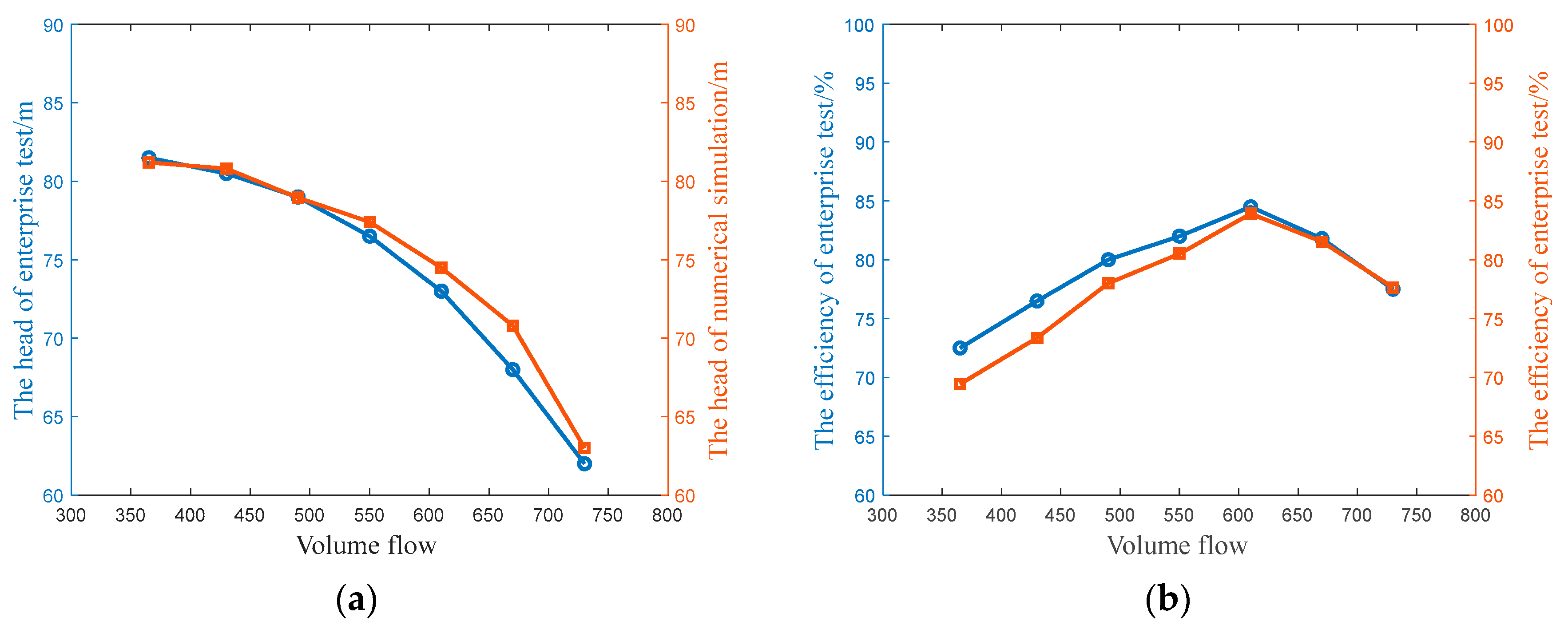
2.3. Model Validation

In order to verify the accuracy of the numerical simulation, the external performances of the centrifugal pump are measured experimentally. The test is carried out on the experimental pump platform of Xi’an Pump and Valve plant Co Ltd. The experimental platform includes the pressure supply pump, flow regulating valve, cavitation suppression tank, flow stabilizing tank and measuring instrument and other components. Figure 3 compares the experimental results and numerical values of the external performances of the centrifugal pump. At the operating point, the relative errors between the numerical calculation and the test results are 0.6% and 0.8%, respectively. In the range of calculated flow operating conditions, the relative errors of efficiency and head are less than 3.0%, which is within a reasonable range. Therefore, the numerical model established in this paper can accurately predict the hydraulic performance of the centrifugal pump and has good reliability.

3. Results and Discussion

3.1. Analysis of Numerical Simulation Results of External Performances

Figure 4 shows the change of the inducer head and the impeller head at different axial spaces. The head of the impeller is reduced compared with the design head. The head of the inducer is increased compared with the design head. With the increase of the axial space, the head of the inducer decreases rapidly at first and then remains basically unchanged. The installation of the inducer produces positive pre-rotation at the inlet of the impeller, and the impeller head decreases. The impeller has a positive effect on the inducer head, but this effect is weakened by an increase in the axial space.
Figure 5 shows the change of the inducer head and the impeller head at different circumferential deflections. With the increase of the circumferential deflection, the inducer head is basically unchanged, and the impeller head shows a trend of first decreasing and then increasing. It can be seen from Figure 4 and Figure 5 that for the impeller head, the circumferential deflection has a greater influence than the axial space. However, for the inducer head, the effect of axial space is greater.

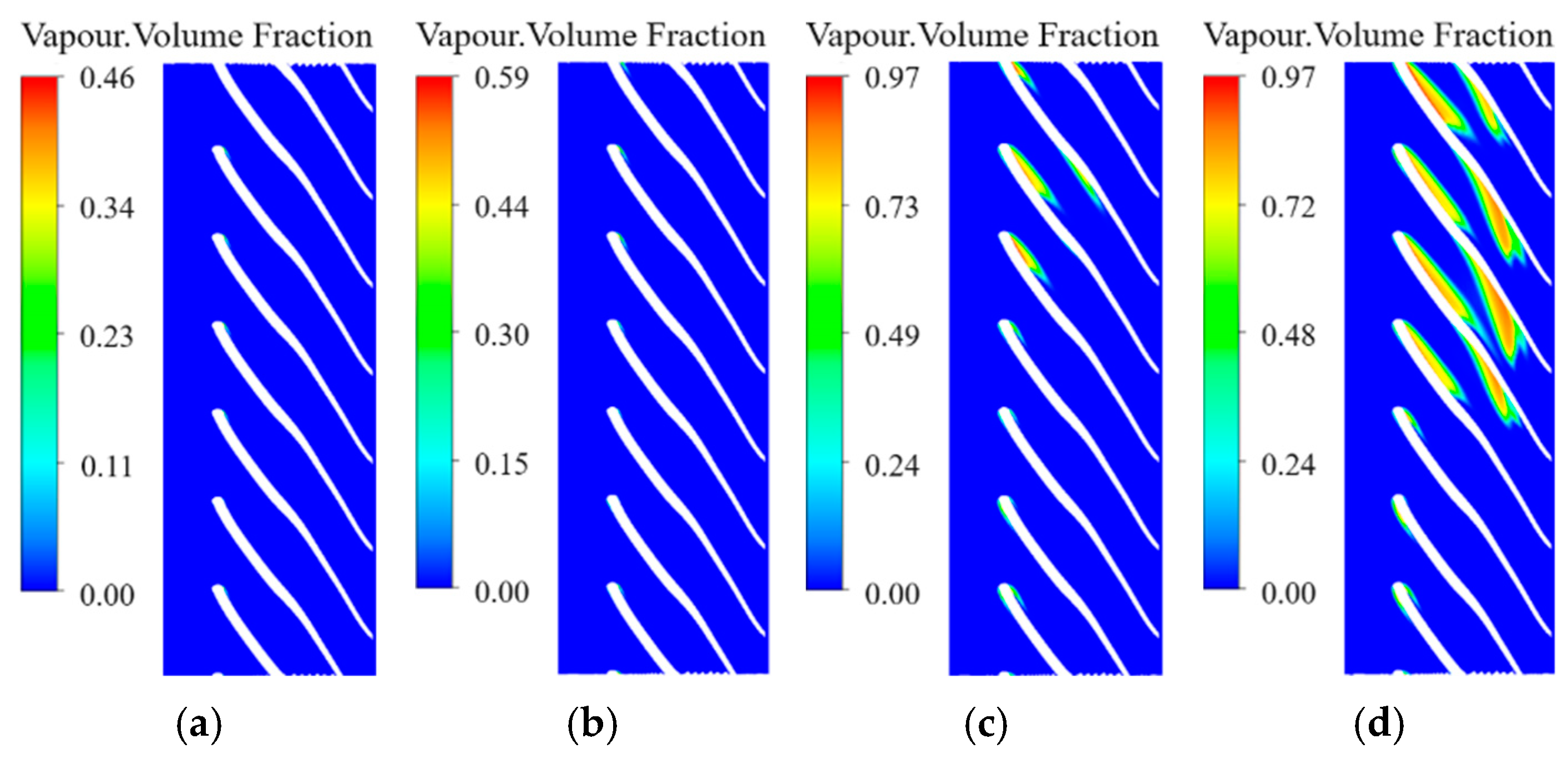
3.2. The Effect of the Inducer on Incipient Cavitation

Figure 6 and Figure 7 compare the water vapor bubble distribution in the impeller before and after installing the inducer. After installing the inducer, with the same net positive suction head available (NPSHa), the bubble volume was significantly smaller than before installing the inducer. The incipient cavitation performance at the inlet of the impeller was significantly improved by installing the inducer.

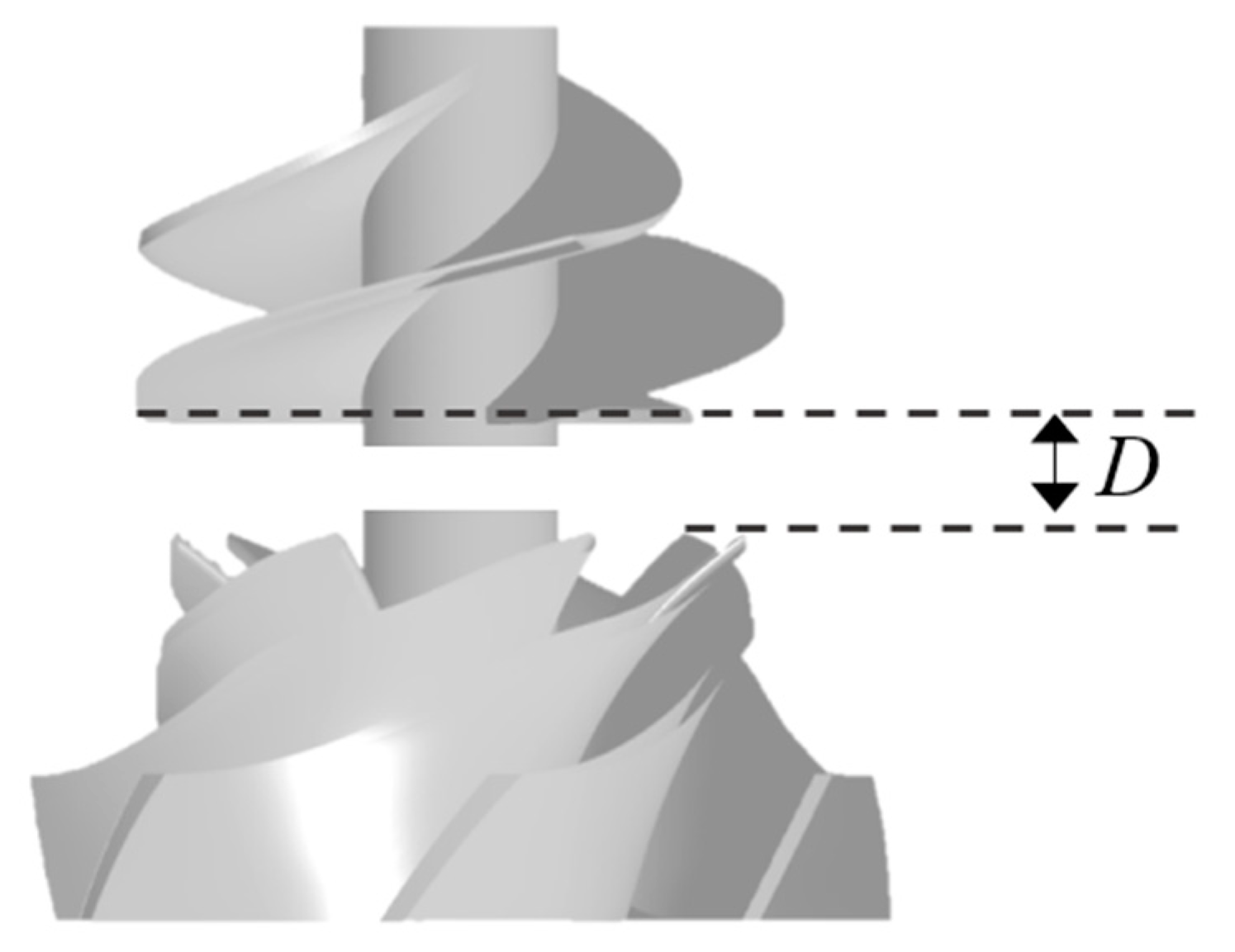
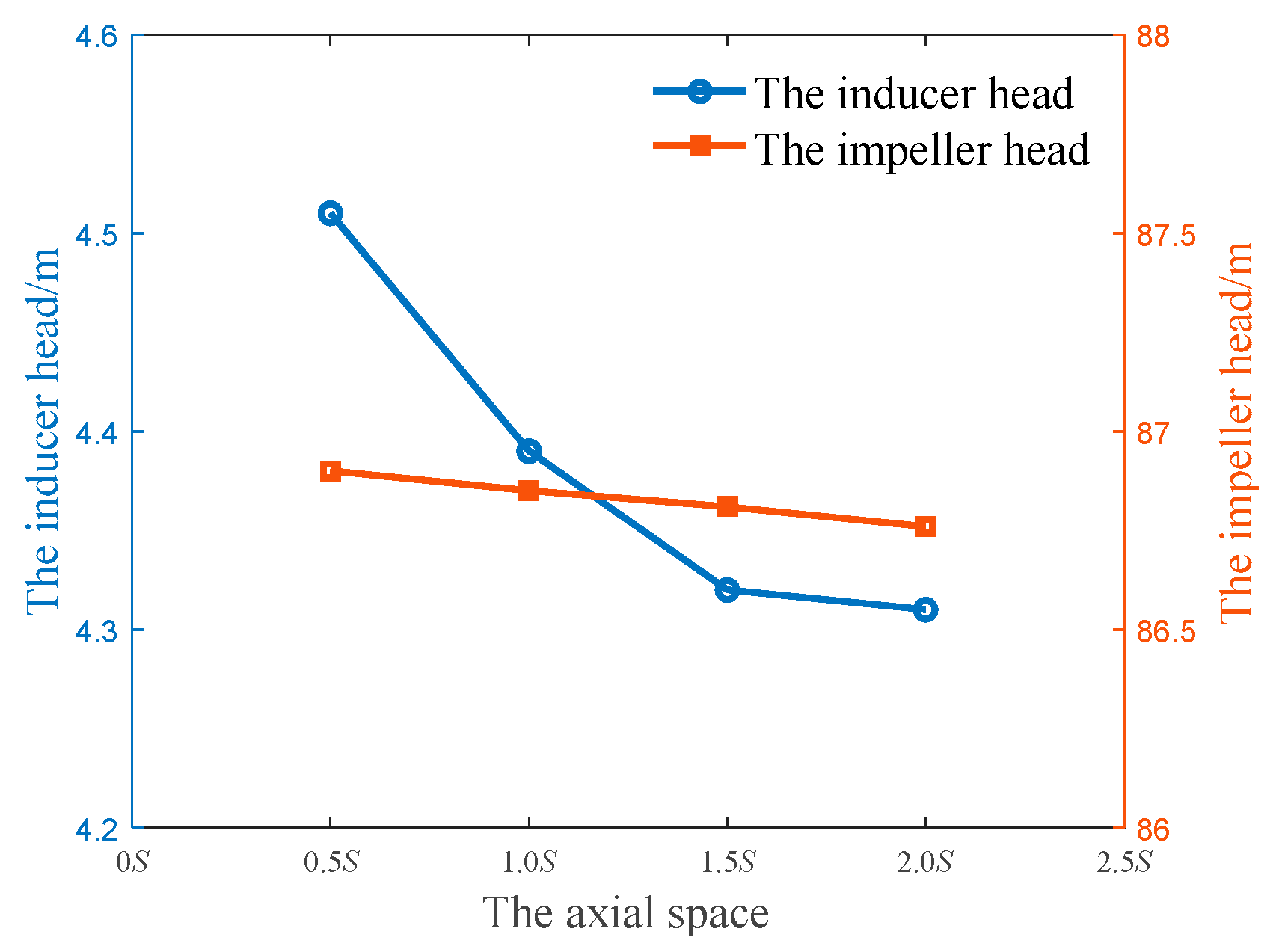
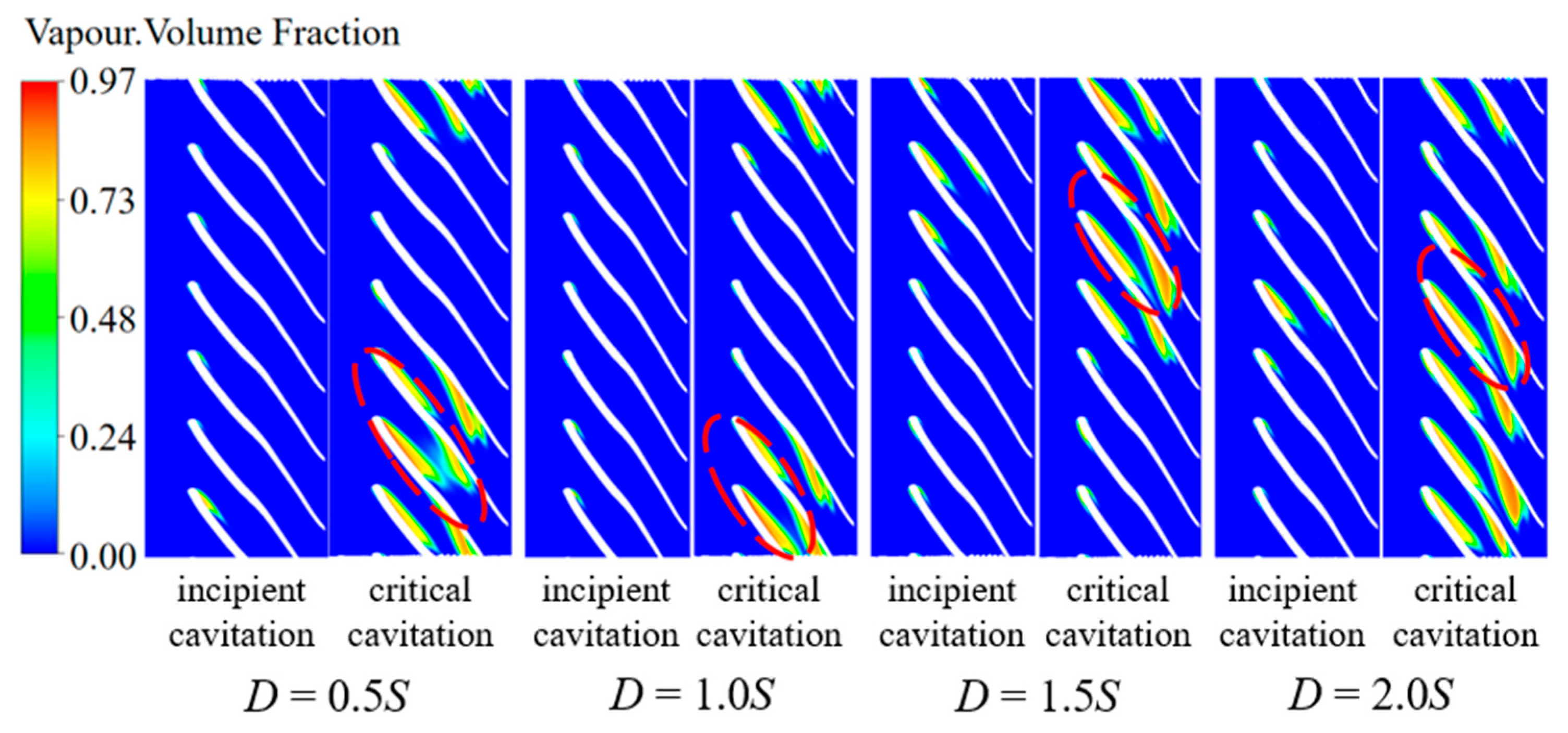
3.3. The Effect of the Axial Space on Cavitation Development

Figure 8 shows the change of the head of the centrifugal pump with different NPSHa under each axial space, and Figure 9 shows the change of the suction-specific speed with the axial space. With the increase of the axial space, the suction-specific speed increases, and the cavitation performance is obviously improved.
Figure 10, Figure 11, Figure 12 and Figure 13 show the water vapor bubble distribution in the impeller under different NPSHa when the axial spaces are 0.5S, 1.0S, 1.5S and 2.0S. As the NPSHa decreases, cavitation occurs at the inlet of the impeller suction surface, and the volume of bubbles increases. The appearance of bubbles changes the inlet shape of the flow channel and then changes the flow angle of the fluid in the flow channel. With the further decrease of NPSHa, bubbles appear in the middle of the pressure surface, the flow passage is blocked, and the impeller cannot work normally.
Figure 14 compares the velocity distribution at each position before and after the installation of the inducer. The area where the velocity is higher than 20 m/s is hereinafter referred to as the high-speed area. As can be seen from Figure 14d, the inlet velocity of the impeller is periodically distributed in the circumferential direction when there is no inducer. Considering the problems of pressure pulsation and vibration noise, the number of inducer blades and impeller blades are mutual prime. The number of inducer blades is 3, and the number of impeller blades is 7 in this paper. Figure 14a–c shows the velocity distribution from the inducer outlet to the impeller inlet. Due to the combined effect of sliding in the inducer and the suction of the impeller, the inlet velocity of each flow channel no longer presents periodic distribution after the inducer is installed. The velocity distribution at the inlet of the impeller changes after the inducer installation, and the rotational symmetry of velocity distribution at the inlet of the impeller is destroyed.
In this paper, it is considered that there are two main reasons limiting the cavitation performance of the pump: inlet pressure and inlet velocity distribution. When any flow channel is blocked because of the generation of bubbles, the blockage phenomenon rapidly develops at the adjacent flow channel; the pump performance is greatly reduced. Therefore, when studying the critical cavitation performance of a centrifugal impeller, it is necessary to pay attention to the flow channel with the most serious cavitation phenomenon.
Figure 15 shows the velocity distribution at different positions with different axial spaces. With the increase of axial space, the influence of the inducer on the velocity distribution of the impeller inlet is gradually weakened, the maximum velocity of the impeller inlet decreases, the difference of maximum velocity of each flow channel decreases, and the periodicity of flow velocity at the impeller inlet is improved.
Figure 16 compares the development process of cavitation in the impeller with different axial spaces. The red oval box marks the flow channel with the worst cavitation. Because of the uneven distribution of the inlet velocity, cavitation of the impeller first occurs in a part of the flow channels. With the increase of axial space, although the number of cavitation channels increases, the distribution of bubbles in each channel becomes more uniform, and the cavitation degree of the most serious cavitation phenomenon decreases. The inlet pressure of the impeller gradually becomes the main reason affecting the cavitation performance of the pump. The cavitation performance is improved.

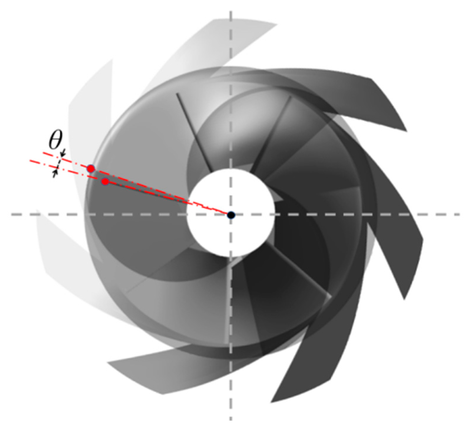
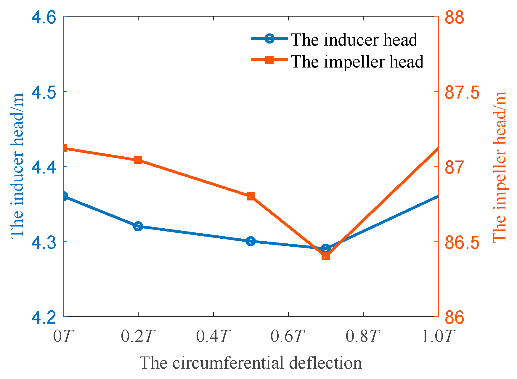
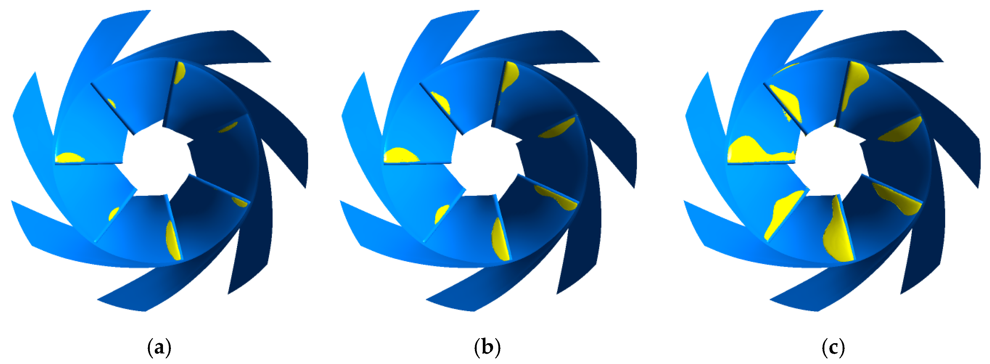
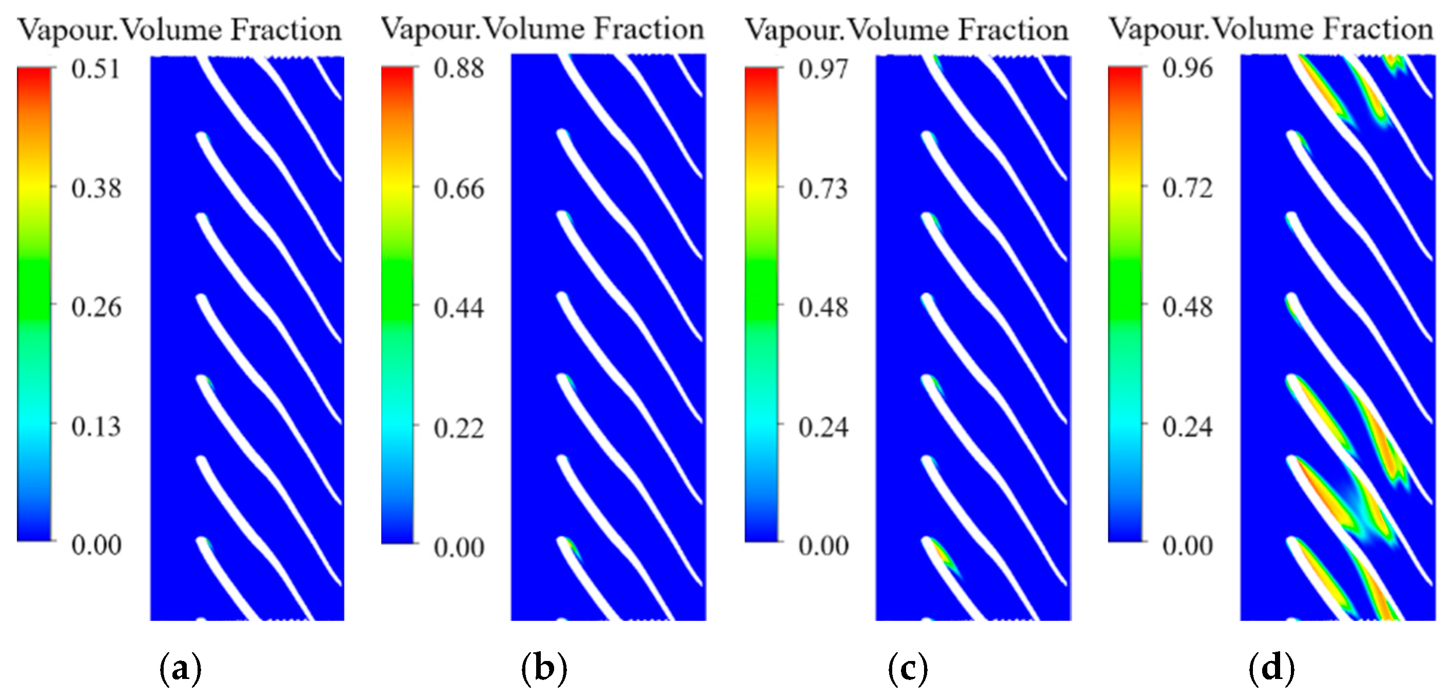
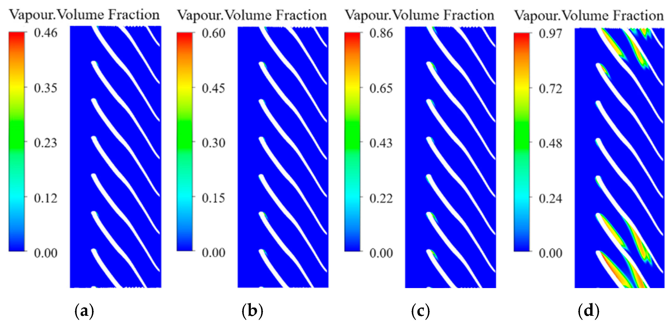
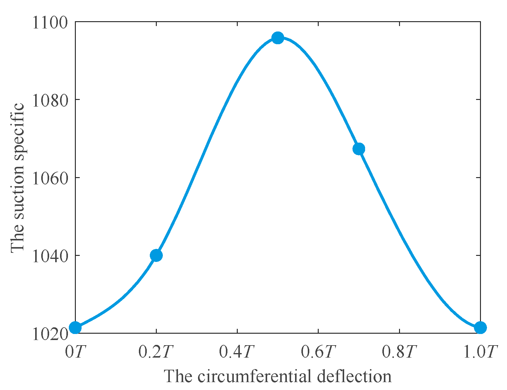
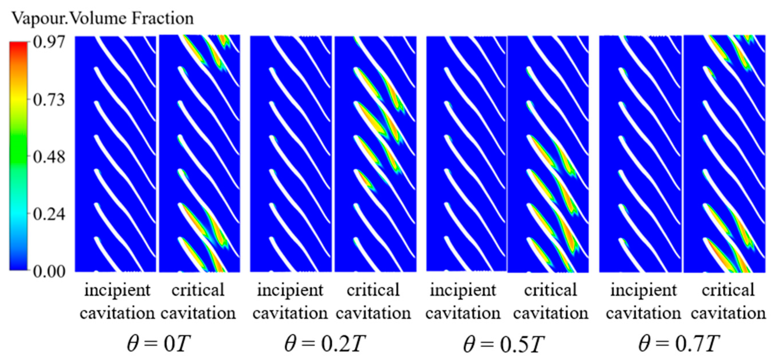
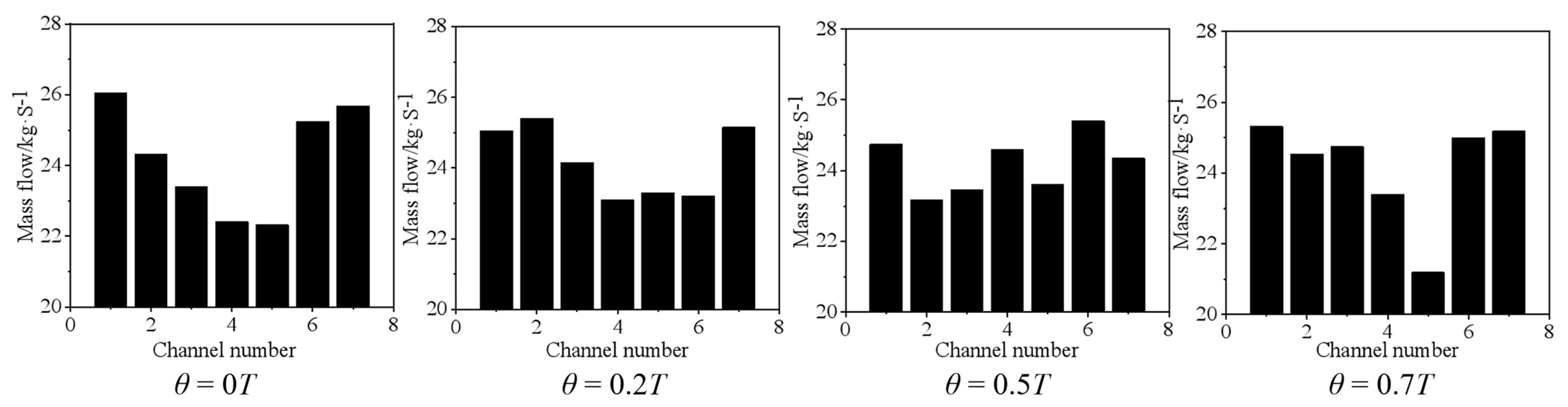
3.4. The Effect of the Circumferential Deflection on Cavitation Development

Figure 17 shows the change of the head of the centrifugal pump with different NPSHa under each circumferential deflection, and Figure 18 shows the change of the suction-specific speed with the circumferential deflection. With the increase of the circumferential deflection, the suction-specific speed increases first and then decreases, and there is an optimal value of the circumferential deflection that maximizes the cavitation-specific speed. By comparing Figure 18 with Figure 9, the circumferential deflection has less effect on the cavitation performance of the pump than the axial space.
Figure 19 compares the development of cavitation in different circumferential deflection cases. In different circumferential deflection cases, the number of flow channels with incipient cavitation in the impeller is basically the same, and the degrees of the flow channel with the most serious cavitation degree are basically the same. Therefore, the effect of circumferential deflection on the incipient cavitation is less than that of the axial space.
Figure 20, Figure 21 and Figure 22 show the distribution of velocity, the angle of attack distribution at the height of the 0.5 blade and the flow distribution of each flow channel under different circumferential deflection cases. When the angle of attack is large, the fluid pressure rises, and the velocity decreases. Under the premise of constant flow, the flow velocity of the adjacent flow channel increases, and the pressure decreases. Once the pressure is lower than the vaporization pressure at the temperature, the liquid vaporizes to produce air masses, and cavitation occurs. There is an optimal circumferential deflection to avoid the large high-speed area, reduce the occurrence of cavitation phenomenon, and improve the cavitation performance of the pump.

4. Conclusions

In this paper, numerical simulations are employed to study the effects of matching, specifically, the axial space and the circumferential deflection between the inducer and the impeller, on the cavitation performance. By analyzing the flow field characteristics, we draw the following conclusions.
  • Generally, it is believed that the inducer would maintain the propulsion performance and suppress the cavitation damage. In fact, the inducer does have an inhibition effect on the incipient cavitation, but whether the critical cavitation performance can be improved is closely related to the matching between the inducer and the impeller. This is because the inducer destroys the rotational symmetry of the flow at the impeller inlet, making the cavitation of some channels more serious than other channels. Once a channel is blocked due to cavitation, the adjacent channel will also be blocked. These channels under serious cavitation will limit the overall cavitation performance. Therefore, even if the inducer provides the flow with energy, it still may not improve the critical cavitation performance.
  • A numerical simulation of a centrifugal pump with a critical cavitation ratio of 1024 was carried out. Under the premise of maintaining the same circumferential deflection, the suction-specific speed is increased by about 300 by adjusting the axial space. Under the premise of maintaining the same axial space, the suction-specific speed is increased by nearly 100 by adjusting the circumferential deflection.
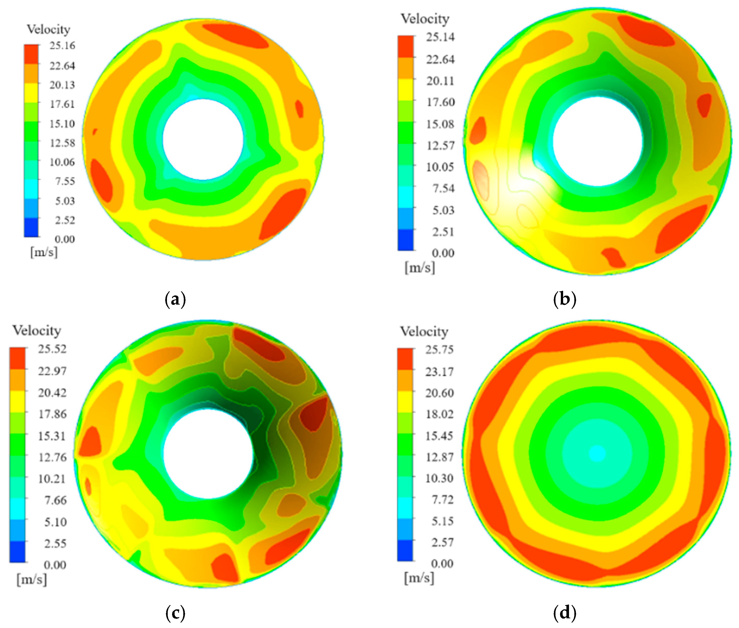
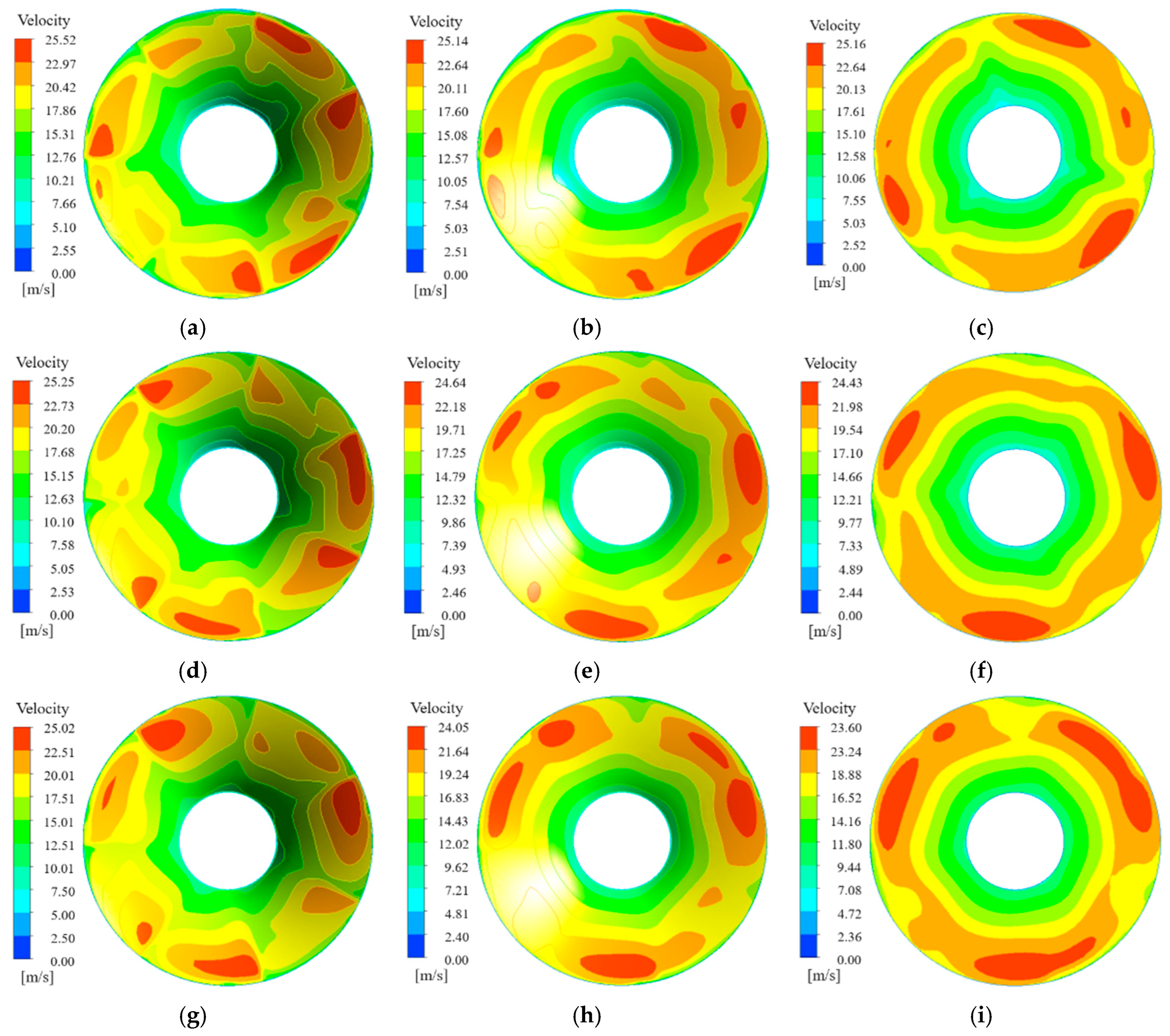
  • With the increase of axial space, the distribution of bubbles in each flow channel under the same NPSHa becomes more uniform. The flow in the channel with the most serious cavitation phenomenon is improved, and the cavitation performance of the pump becomes better. Meanwhile, for circumferential deflection, when the angle of attack is large, the flow velocity of the adjacent flow channel increases, and the pressure decreases. There is an optimal value of circumferential deflection to avoid large high-speed areas, which has the best cavitation performance. The axial space has a greater effect than the circumferential deflection on the cavitation performance of the pump.

Author Contributions

Conceptualization, D.W. and Y.C.; methodology, D.W., Y.C. and L.L. (Lei Liu); software, L.L. (Lijun Liu); validation, B.G. and Q.W.; formal analysis, D.W. and Y.C.; investigation, D.W. and Y.C.; resources, B.G. and Q.W.; writing—original draft preparation, D.W.; writing—review and editing, D.W., J.L. and L.L. (Lijun Liu); visualization, D.W., Y.C. and Y.P.; project administration, L.L. (Lijun Liu), Q.W., J.L., B.G. and D.W.; funding acquisition, B.G. and Q.W. All authors have read and agreed to the published version of the manuscript.

Funding

This work is supported by the National Key R&D Program of China (no. 2018YFB0606104) and the joint research project (no. 202106198) between Xi’an Jiaotong University and Xi’an Pump and Valve plant Co., Ltd. (Xi’an, China).

Institutional Review Board Statement

Not applicable.

Informed Consent Statement

Not applicable.

Data Availability Statement

Not applicable.

Conflicts of Interest

The authors declare no conflict of interest.

References

  1. Ge, M.; Petkovšek, M.; Zhang, G.; Jacobs, D.; Coutier-Delgosha, O. Cavitation dynamics and thermodynamic effects at elevated temperatures in a small Venturi channel. Int. J. Heat Mass Transf. 2021, 170, 120970. [Google Scholar] [CrossRef]
  2. Ge, M.; Manikkam, P.; Ghossein, J.; Subramanian, R.K.; Coutier-Delgosha, O.; Zhang, G. Dynamic mode decomposition to classify cavitating flow regimes induced by thermodynamic effects. Energy 2022, 254, 124426. [Google Scholar] [CrossRef]
  3. Fan, Y.; Chen, T.; Liang, W.; Wang, G.; Huang, B. Numerical and theoretical investigations of the cavitation performance and instability for the cryogenic inducer. Renew. Energy 2022, 184, 291–305. [Google Scholar] [CrossRef]
  4. Kim, H.; Kim, C. A physics-based cavitation model ranging from inertial to thermal regimes. Int. J. Heat Mass Transf. 2021, 181, 121991. [Google Scholar] [CrossRef]
  5. Hou, X.Y.; Hu, J.; Yu, Y. Numerical Simulation and Evaluation of Attached Cavitation with Different Cavitation Models. Acta Armamentarii 2020, 41, 91–96. [Google Scholar]
  6. Hu, J.; Hou, X.Y.; Yu, Y. Improvement and Application of Zwart-Gerbera-Belamri CavitationModel with Local Flow Properties. Trans. Beijing Inst. Technol. 2021, 41, 388–394. [Google Scholar]
  7. Zhang, G.; Zhang, D.; Ge, M.; Shi, W. Experimental validation to Reboud empirical correction model of cavitation. J. Huazhong Univ. Sci. Technol. (Nat. Sci. Ed.) 2022, 1–6. [Google Scholar] [CrossRef]
  8. Bakir, F.; Kouidri, S.; Noguera, R.; Rey, R. Experimental analysis of an axial inducer influence of the shape of the blade leading edge on the performance in cavitating regime. J. Fluids Eng. 2003, 125, 293–301. [Google Scholar] [CrossRef]
  9. Saha, S.L.; Kurokawa, J.; Matsui, J.; Imamura, H. Passive control of rotating stall in a parallel wall vaned diffuser by J-grooves. J. Fluids Eng. 2000, 122, 90–96. [Google Scholar] [CrossRef]
  10. Benoît, P.; Regiane, F.P.; Jean-Luc, R.; Pierre-Alain, L. Numerical analysis of cavitation instabilities in inducer blade cascade. J. Fluids Eng. 2008, 130, 1441–1448. [Google Scholar]
  11. Cui, B.L.; Zhu, Z.C.; Lin, Y.G. Numerical simulation of inner flow in equal-pitch inducer. J. Agric. Eng. 2010, 46, 158–163. [Google Scholar] [CrossRef]
  12. Qiu, N.; Wang, L.Q.; Kong, F.Y. Research on cavitation characteristic of inducer. IOP Conf. Ser. Mater. Sci. Eng. 2013, 52, 668–672. [Google Scholar] [CrossRef] [Green Version]
  13. Guo, X.M.; Li, Y.; Cui, B.L.; Zhu, Z.C. Research on the rotation cavitation performance of high-speed rotation centrifugal pump with different pre-positioned inducers. Acta Aeronaut. Astronaut. Sin. 2013, 34, 1572–1581. [Google Scholar]
  14. Kang, D.; Yokota, K. Analytical study of cavitation surge in a hydraulic system. J. Fluids Eng. 2014, 136, 1011031–10110310. [Google Scholar] [CrossRef]
  15. Zhang, A. Effect of the Geometric Parameters at Inlet of Inducer and Itself on Cavitation Characteristics of Centrifugal Pump. Master’s Thesis, Lanzhou University of Technology, Lanzhou, China.
  16. Chen, X.; Yang, D.; Liu, J. Influence of annular groove position on cavitation performance of high-speed inducer. J. Drain. Irrig. Mach. Eng. 2021, 39, 548–554. [Google Scholar]
  17. Lu, X. Research on the effect of front-end flow stabilizer devices on high-speed inducer cavitation characteristics. Master’s Thesis, Lanzhou University of Technology, Lanzhou, China.
  18. Wang, R. Study on optimization design and cavitation characteristics high-speed centrifugal pump with inducer. Master’s Thesis, Jiangsu University, Zhenjiang, China.
  19. Leng, H.F.; Yao, Z.F.; Tang, Y.; Wang, C.Y.; Zhao, H.R. Matching characteristics of axial distance between inducer and impeller of micro-centrifugal pump. Trans. Chin. Soc. Agric. Eng. 2020, 36, 47–53. (In Chinese) [Google Scholar]
  20. Li, R.N.; Bi, Z.; Li, Y.B.; Xiao, L.Q. Effect of inducer deflection angle on impeller cavitation performance in centrifugal pump. J. Drain. Irrig. Mach. Eng. 2016, 34, 461–469. [Google Scholar]
  21. Sun, Q.Q.; Jiang, J.; Zhang, S.S. Effects of variable pitch inducer on cavitation performance of high-speed centrifugal pumps. J. Drain. Irrig. Mach. Eng. 2017, 35, 856–862. [Google Scholar]
  22. Wang, W.T.; Chen, H.; Li, Y.P.; Du, Y. Matching research of inducer and impeller of high-speed centrifugal pump. J. Drain. Irrig. Mach. Eng. 2015, 33, 301–305. [Google Scholar]
  23. Lu, J.L.; Deng, J.; Xu, Y.R.; Feng, J.; Luo, X. Study on axial spacings between inducer and impeller of centrifugal pump. J. Hydroelectr. Eng. 2015, 34, 91–96. [Google Scholar]
  24. Cheng, X.; Liu, H.; Wu, C.; Wei, Y. Influence of matching of blade number of inducer with impeller on cavitation performance of pump. J. Lanzhou Univ. Technol. 2019, 45, 53–58. [Google Scholar]
  25. Liu, H. Research on the Matching Characteristics of Inducer and Impeller of Centrifugal Pump. Master’s Thesis, Lanzhou University of Technology, Lanzhou, China.
  26. Guan, X.F. Morden Pumps Theory and Design, 1st ed.; Zhong Guo Yu Hang Chu Ban She: Beijing, China, 2011; pp. 455–470. [Google Scholar]
  27. Wang, F.J. Research progress of computational model for rotating turbulent flow in fluid machinery. Trans. Chin. Soc. Agric. Mach. 2016, 47, 1–14. [Google Scholar]
  28. Zhang, X.X.; Zhang, Z.T.; Zhang, W.F.; Chen, Z. Comparison of five eddy viscosity turbulence models in numerical simulation of flow over a two-dimensional square cylinder. Acta Aerodyn. Sin. 2018, 36, 339–349. [Google Scholar]
  29. Ren, Y.; Wu, D.; Mou, Y.; Li, X. Modification for Turbulence Model Considering Rotation and Curvature with Applications. J. Xi’an Jiaotong Univ. 2016, 50, 25–30. [Google Scholar]
  30. Patankar, S.V.; Spalding, D.B. A calculation pressure for heat, mass and momentum transfer in three-dimensional parabolic flows. In Numerical Prediction of Flow, Heat Transfer, Turbulence and Combustion; Pergamon: Oxford, England, 1983; pp. 54–73. [Google Scholar]
  31. Van Doormaal, J.P.; Raithby, G.D. Enhancement of the SIMPLE method for predicting incompressible fluid flows. Numer. Heat Transf. 1984, 7, 147–163. [Google Scholar] [CrossRef]
Figure 1. The definition of the axial space.
Machines 11 00142 g001
Figure 2. The definition of circumferential deflection.
Machines 11 00142 g002
Figure 3. Comparison between experimental results and numerical simulation results: (a) The comparison of the head; (b) The comparison of the efficiency.
Machines 11 00142 g003
Figure 4. The change of the inducer head and the impeller head at different axial spaces.
Machines 11 00142 g004
Figure 5. The change of the inducer head and the impeller head at different circumferential deflections.
Machines 11 00142 g005
Figure 6. Isosurface distribution of bubble volume fraction of 10% in the impeller channel without the inducer: (a) NPSHa = 16 m; (b) NPSHa = 13 m; (c) NPSHa = 10 m.
Machines 11 00142 g006
Figure 7. Isosurface distribution of bubble volume fraction of 10% in the impeller channel with the inducer: (a) NPSHa = 16 m; (b) NPSHa = 13 m; (c) NPSHa = 10 m.
Machines 11 00142 g007
Figure 8. The change of the head with different NPSHa under each axial space.
Machines 11 00142 g008
Figure 9. The change of the suction-specific speed with the axial space.
Machines 11 00142 g009
Figure 10. Bubble distribution in the impeller with different NPSHa with the axial space of 0.5S: (a) NPSHa = 19 m; (b) NPSHa = 16 m; (c) NPSHa = 13 m; (d) NPSHa = 11 m.
Machines 11 00142 g010
Figure 11. Bubble distribution in the impeller with different NPSHa with the axial space of 1.0S: (a) NPSHa = 19 m; (b) NPSHa = 16 m; (c) NPSHa = 13 m; (d) NPSHa = 12 m.
Machines 11 00142 g011
Figure 12. Bubble distribution in the impeller with different NPSHa with the axial space of 1.5S: (a) NPSHa = 19 m; (b) NPSHa = 16 m; (c) NPSHa = 10 m; (d) NPSHa = 9 m.
Machines 11 00142 g012
Figure 13. Bubble distribution in the impeller with different NPSHa with the axial space of 2.0S: (a) NPSHa = 19 m; (b) NPSHa = 16 m; (c) NPSHa = 10 m; (d) NPSHa = 8 m.
Machines 11 00142 g013
Figure 14. The velocity distribution at each position before and after the installation of the inducer: (a) The velocity distribution at the position 20 mm away from the impeller after the installation of the inducer; (b) The velocity distribution at the position 10 mm away from the impeller after the installation of the inducer; (c) The velocity distribution at the impeller inlet after the installation of the inducer; (d) The velocity distribution at the impeller inlet before the installation of the inducer.
Machines 11 00142 g014
Figure 15. The velocity distribution at each position with different axial spaces: (a) The velocity distribution at the impeller inlet when D = 0.5S; (b) The velocity distribution at the position 10 mm away from the impeller when D = 0.5S; (c) The velocity distribution at the position 20 mm away from the impeller when D = 0.5S; (d) The velocity distribution at the impeller inlet when D = 1.0S; (e) The velocity distribution at the position 10 mm away from the impeller when D = 1.0S; (f) The velocity distribution at the position 20 mm away from the impeller when D = 1.0S; (g) The velocity distribution at the impeller inlet when D = 2.0S; (h) The velocity distribution at the position 10 mm away from the impeller when D = 2.0S; (i) The velocity distribution at the position 20 mm away from the impeller when D = 2.0S.
Machines 11 00142 g015
Figure 16. The development process of cavitation in the impeller in different axial space cases, in which red oval boxes mark the flow channel with the worst cavitation.
Machines 11 00142 g016
Figure 17. The change of the head with different NPSHa under each circumferential deflection.
Machines 11 00142 g017
Figure 18. The change of the suction-specific speed with the circumferential deflection.
Machines 11 00142 g018
Figure 19. The development process of cavitation in the impeller in different circumferential deflection cases.
Machines 11 00142 g019
Figure 20. Velocity distribution in different circumferential deflection cases: (a) θ = 0T; (b) θ = 0.2T; (c) θ = 0.5T; (d) θ = 0.7T.
Machines 11 00142 g020
Figure 21. The angle of attack distribution at the height of the 0.5 blade in different circumferential deflection cases.
Machines 11 00142 g021
Figure 22. The flow distribution in different circumferential deflection cases.
Machines 11 00142 g022
Disclaimer/Publisher’s Note: The statements, opinions and data contained in all publications are solely those of the individual author(s) and contributor(s) and not of MDPI and/or the editor(s). MDPI and/or the editor(s) disclaim responsibility for any injury to people or property resulting from any ideas, methods, instructions or products referred to in the content.

