Article

An Adaptive Control Method for the Distribution Valve of a Digital Pump

1
Energy and Power Engineering College, Lanzhou University of Technology, Lanzhou 730050, China
2
School of Mechanical Science and Engineering, Huazhong University of Science and Technology, Wuhan 430074, China
3
Taiyuan Research Institute, China Coal Technology and Engineering Group, Taiyuan 030006, China
*
Author to whom correspondence should be addressed.
Machines 2023, 11(2), 148; https://doi.org/10.3390/machines11020148
Submission received: 7 December 2022 / Revised: 12 January 2023 / Accepted: 19 January 2023 / Published: 21 January 2023
(This article belongs to the Special Issue Mechatronic Systems: Developments and Applications)

Abstract

:
Perfect flow distribution is extremely important and essential for digital pumps. However, the fluctuation of motor speed and the change of valve dynamic characteristics cause the flow distribution flaw, which generates the backflow of the oil in the piston chamber and the decrease in pump volumetric efficiency. Based on the three-dimensional and mathematical modeling of the digital pump, the perfect distribution state of the digital pump is analyzed. Then, the adverse effects of the variations in motor speed and valve dynamic characteristics on the flow distribution of the digital pump were simulated and investigated by the software AMESim. To overcome the aforementioned problems, we proposed an adaptive control method for the flow distribution valve of a digital pump, which was realized by adopting the axis rotation angle and the pressure difference between the inlet and outlet of the flow distribution valve. The results show that the control signal of the flow distribution valve can be regulated automatically along with the motor speed and the valve dynamic characteristics, achieving the ideal flow distribution of the digital pump designed in this paper. The study can be used as a reference for the optimal design and prototype manufacturing of the digital pump.

1. Introduction

Digital hydraulics technology has been rapidly developed and researched for applications in recent years. Its core is the discrete control of flow through the active and intelligent control of digital valves [1]. Digital hydraulic pumps adopt the above solution, and the chamber is independently controlled by using two digital valves. The chamber that is used is activated, and the ones not operated are banned. As a result, more intelligent control and less energy loss are realized [2]. However, the efficiency is affected by the response speed and the timing of the flow distribution valve (FDV). To further improve the operating characteristics and efficiency of the digital pump, improving the response times of the FDV is an effective and convenient manner.
With respect to the dynamic response of FDV, Zhao et al. investigated the effect of control current and voltage on the dynamic characteristics of FDV. Finite element analysis found that there was a balance between energy consumption and improvement of response speed [3,4]. Because the FDV is affected by different supply pressure, carrier frequencies, and coil temperatures, Su et al. proposed a dual voltage adaptive switching method, which can change adaptively according to the oil supply pressure and control port pressure [5]. Gao et al. put forward an adaptive PWM control method consisting of four PWM signals for FDV, the rising time of the pressure was reduced by 84.6%, and the temperature of the coil shell declined by 61.5 % [6]. Zhong et al. proposed a method for FDV which can adaptively select among multiple driving voltage sources when the oil supply pressure changes [7]. Zhong et al. also presented an FDV control method with adaptive switching among five drive voltages, which reduced the open delay time by 66.7%, and lowered the close delay time by 87.5% [8]. Chapple et al. proposed a new type of poppet valve as FDV, and it is applied to high torque and low-speed systems to obtain higher efficiency and displacement control performance, but there are challenges with start-stop, valve timing, overpressure protection, and valve actuators [9]. The solenoid screw-in cartridge valves (SCV) are seen as having the potential to be applied to digital pumps. To improve the dynamic response of SCV and make it meet the flow distribution requirement of digital pumps. Yue et al. adopted positive and negative pulse voltage control for the solenoid coil, and the dynamic response characteristics are significantly enhanced by 56.67% compared to the conventional method [10]. Liu et al. proposed a new hybrid voltage control method consisting of preload voltage, positive pulse voltage, hold voltage, and negative pulse voltage, which reduced the open delay time by 74.24% and reduced the close delay time by 92.06% [11].
In the matter of flow distribution characteristics and control strategies for a digital pump, Pan et al. simulated the flow distribution characteristics of the FDV groups under clockwise and counterclockwise strokes of the motor, the steering variation process of the motor, and the effect of the switching valve frequency on the hydraulic motor [12]. Pederson et al. proposed continuous, discrete, hybrid dynamic approximate methods for digital pumps/motors, but there are still many challenges to be solved [13,14,15,16]. Based on the three pistons pump/motor, Breidi proposed a prediction for valve response delay time and mode switching algorithm using pressure fluctuations in high and low pressure lines, realizing an automatic selection of the most efficient control strategy among different displacement control strategies [17,18]. Nordas et al. detailed a simulation of the transient and steady-state response of digital displacement motors with full-stroke, partial-stroke, or sequential partial-stroke [19].
However, due to the changes in oil and coil temperature, the dynamic characteristics of the FDV can not always hold a constant in the operation of digital pumps [20,21]. In addition, the motor speed suffers from variations in the power grid. The above changes result in a flow distribution flaw in the digital pump, failing to achieve the expected flow distribution, which is manifested by fluid backflow and loss of volumetric efficiency during digital pump operation.
Therefore, an adaptive flow distribution control strategy of the digital pump is proposed to deal with the issue. The word “adaptive” refers to the ability of the proposed control method to maintain the perfect flow distribution of the FDV under the above variation. Firstly, we performed three-dimensional and mathematical modeling of the digital pump in Section 2. Secondly, in Section 3 and Section 4, we analyzed the working characteristics of the digital pump with a perfect distribution and conducted a model-based simulation to investigate the impact of the changes in the motor speed and the dynamic characteristics of the FDV on a digital pump. Then, in Section 5, the principle of the proposed method is explained and verified. Finally, it was concluded that the adaptive control strategy could eliminate flow distribution error and keep the best efficiency, which not only improves the robustness and stability of the digital pump but also promotes the development of digital hydraulic technology.

2. Working Principle and Mathematical Model of the Digital Pump

2.1. Structure and Working Principles of the Digital Pump

A five-piston constant-speed digital pump with auxiliary check valves is shown in Figure 1. The motor converts electrical energy into mechanical energy, which drives the pump shaft and the eccentric cam to rotate. The piston is forced by the eccentric cam to make a sinusoidal motion and achieve fluid output. When the eccentric cam rotates from 0° to 360°, the piston moves from the top dead center (TDC) to the bottom dead center (BDC) and then returns to the initial TDC position; thus, the volume of the piston chamber completes a continuous variation. The piston and eccentric cam do not detach due to the return spring. When the piston moves from TDC to BDC, the piston chamber volume becomes larger, and the pump enters the suction stage, the FDV, known as the high-speed on/off valve, is actively open. If there is an insufficient oil suction, oil replenishment can be completed through the auxiliary check valve. When the piston moves from BDC to TDC, the volume becomes smaller, and the pump switches to the pumping stage in which the high-pressure valve (HPV) is passively open.

2.2. Mathematical Modeling

The overall structure of the digital pump is divided into two parts, one is the flow distribution valve part, and the other is the piston part. The mathematical modeling of the two parts is as follows.

2.2.1. Force Balance and Response Characteristics of the FDV

The force balance of the spool of the FDV can be expressed as:
m x ¨ s = F e F s s F f F f f
On expression, m   represents the total quality of the spool and the armature. X s is the displacement of the spool,   F e   depicts the electromagnetic force of the electromagnetic coil,   F s s   is spring compression force, F f   demonstrates the total friction force of the spool and the armature, and F f f is the flow force of the spool. Among them, the spring force acting on the spool can be expressed as:
F s s = K x 0 + x s
In the above expression, K represents the stiffness coefficient of the spring, and   x 0   represents the initial compression displacement of the spring. The flow force acting F f f can be divided into steady-state flow force and transient flow force. Steady-state flow force and transient flow force can be expressed as:
F s = 2 C d C v A v cos α p
F t = C d w l 2 ρ Δ p x ˙ s
where F s   and F t   are the steady-state and transient hydraulic forces of the spool; C d   and C v   represent the flow coefficient and velocity coefficient of the valve port, respectively; A v   is the flow area of the valve; α and Δ p represent the conical spool jet angle and the pressure difference between the inlet and outlet of the valve; w is the area gradient; l is the damping length; and ρ is the density of the oil.
For the convenience of modeling, this paper reduces the transient response of the FDV to a first-order inertia part and a delay part.
The time-domain response expression of the first-order inertial part is:
h FDV = 1 e 1 T   ·   τ FDV
where τ FDV   is the on/off valve time constant, h FDV   is the spool displacement.

2.2.2. Piston Motion Characteristics

Because the five pistons are identical, all five pistons can be described by modeling a single piston. The displacement of the piston is as follows:
x = L 2 1 cos θ
where L is the effective length of plunger. The relationship between angular displacement and angular velocity of the shaft is as follows:
θ = ω t
In Equation (7), ω is the angular velocity of pump shaft rotation. By substituting Equation (7) into Equation (6), we can obtain the following:
x = L 2 1 cos ω t
By differentiating Equation (9), the piston velocity equation is achieved as follows:
  x ˙ = L 2 ω sin ω t
The variation in pressure in the piston chamber is as follows:
d P d t = β V q H q L d V d t
where P is the pressure in the piston chamber, β is the elastic modulus of oil, V is the volume in the piston chamber, q H is the flow out through HPV, and q L is the flow through the FDV.

2.2.3. Piston Volume Variation Characteristics

With no consideration of the plunger volume leakage, the change in the volume of the plunger chamber can be expressed as:
V = V 0 + x 2 1 cos ω t
where V 0 is the volume of the piston at the initial moment. The derivative of the piston volume is:
d V d t = x 2 ω sin ω t
Instantaneous angle of piston:
θ k = θ 0 + 2 · π n c y l           k ϵ 1 , 2 , , n c y l
Flow through the inlet and outlet of the single FDV:
Q F D V ,   k = C d A 2 · P ρ
The total flow of FDVs:
Q i n = k = 1 n cyl Q F D V , k

3. The Perfect Flow Distribution on Digital Pumps

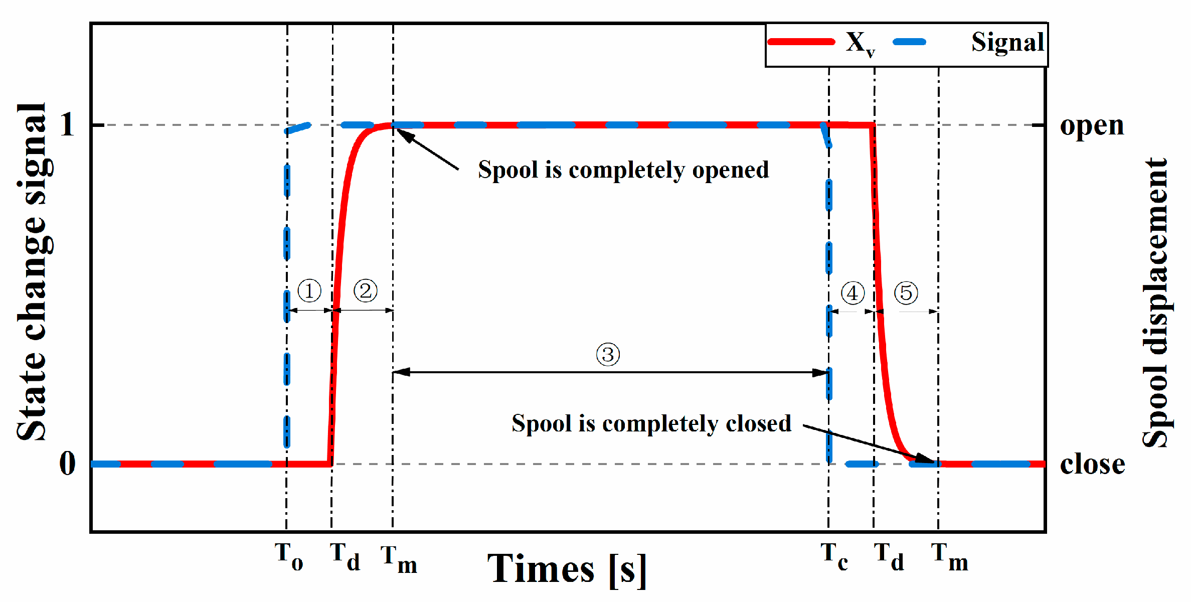
The displacement of the digital pump is permitted to be controlled by different control strategies, and the most common and simple operation is the full-stroke control strategy (FSCS) that is adopted in this paper. In the whole pumping stage, the HPV is passively opening, and the FDV is actively closing. The oil in the piston chamber is compressed into the high-pressure circuit. In the entire suction stage, the FDV is actively opening, and the HPV is passively closing so that the digital pump sucks oil from the tank. Another type of control is the partial stroke control strategy (PSCS). Compared to FSCS, the active control of the FDV in the PSCS is strengthened. Whether the PSCS or FSCS of the digital pump, they both achieve the flow distribution depending on the precise opening and closing of the FDV; consequently, the perfect flow distribution of the digital pump has to consider the dynamic response of the FDV. The dynamic response of the opening and closing process of the FDV is shown in Figure 2. When the FDV receives the opening/closing control signal, the FDV goes through the opening/closing delay stage/ T d   and the spool opening/closing moving stage/ T m   until the response of the FDV is finished.
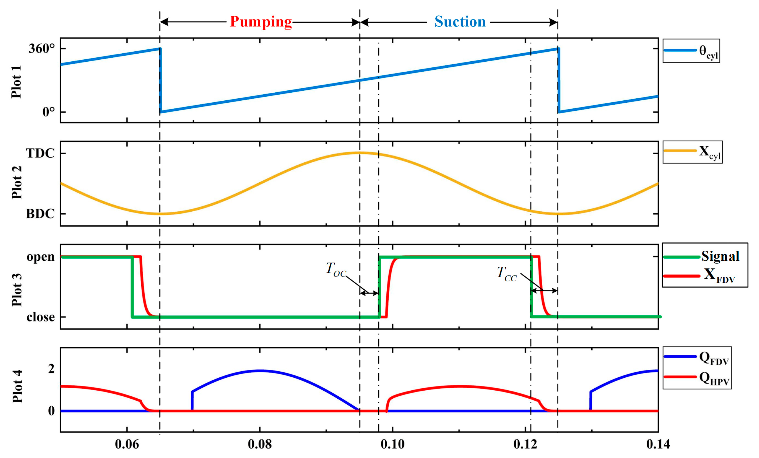
The operating characteristic curve of the digital pump at the perfect flow distribution condition is shown in Figure 3. It can be seen from plot 3 that the signal to open the FDV is made at this point, which is T o c behind the TDC. The decision to close it is made at the moment where T c c is ahead of the BDC. The T o c is added to decompress the piston chamber in advance and make the pressure difference of the FDV equal to zero, which avoids the flow backward of the oil in the piston chamber. The value of T o c is subject to the decompression time of the piston chamber and the spool opening delay stage of the FDV. The T c c is created to ensure that the FDV has been closed completely when the piston reaches the BDC. The settings of T o c must be decided by the sum of the closing delay stage and closing moving stage of the spool. Hence, it is obvious that the T o c and T c c is vital to the perfect flow distribution of the digital pump. From the flow curves of FDV shown in plot 4, it can be seen that the backflow does not occur with the appropriate T o c and T c c that brings the digital pump to the perfect flow distribution.

4. Simulation Modeling and Investigation

4.1. Digital Pump Simulation Model

According to the structure and working principle of the digital pump, it can be seen that the modeling of the digital pump involves multidisciplinary, such as mechanics, hydraulic transmission, electrical control, etc.; therefore, the multi-physics coupling modeling and analysis software AMESim is selected as tools to make study convenient.
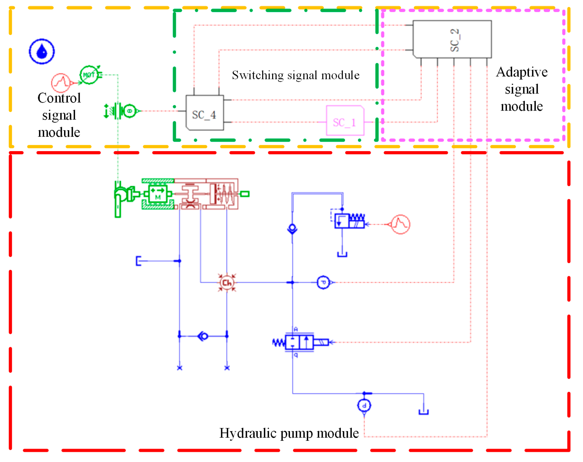
As shown in Figure 4, the digital pump model with one piston is mainly composed of the hydraulic pump module and the control signal module. The control signal module is composed of the switch control signal module (SC_4) (SC_1) and the FDV adaptive signal module (SC_2). The main parameters of the model have been listed in Table 1. During the investigation of the flow distribution error stage, the adaptive signal control module is not involved in the control work. The correctness of the simulation model is verified by comparing the output flow of FDV and HPV, the backflow in simulation, and experiment results from the literature [14,16,17,22].

4.2. Effects of Flow Distribution Error on Digital Pumps

The fluctuation of motor speed and the change in the dynamic characteristics of the FDV both make the FDV open and close at an inappropriate time; in other words, the FDV is activated too early or too late. To facilitate the analysis of the effect of incorrect FDV control on the digital pump, the T o c is selected as −4, −2, 0, 2, and 4 ms, and the T c c is −2, −1, 0, 1, and 2 ms. The greater the T o c is, the later the FDV opens. The maximum T c c means that the FDV first begins to close.

4.2.1. Effects of the Toc on the Digital Pump

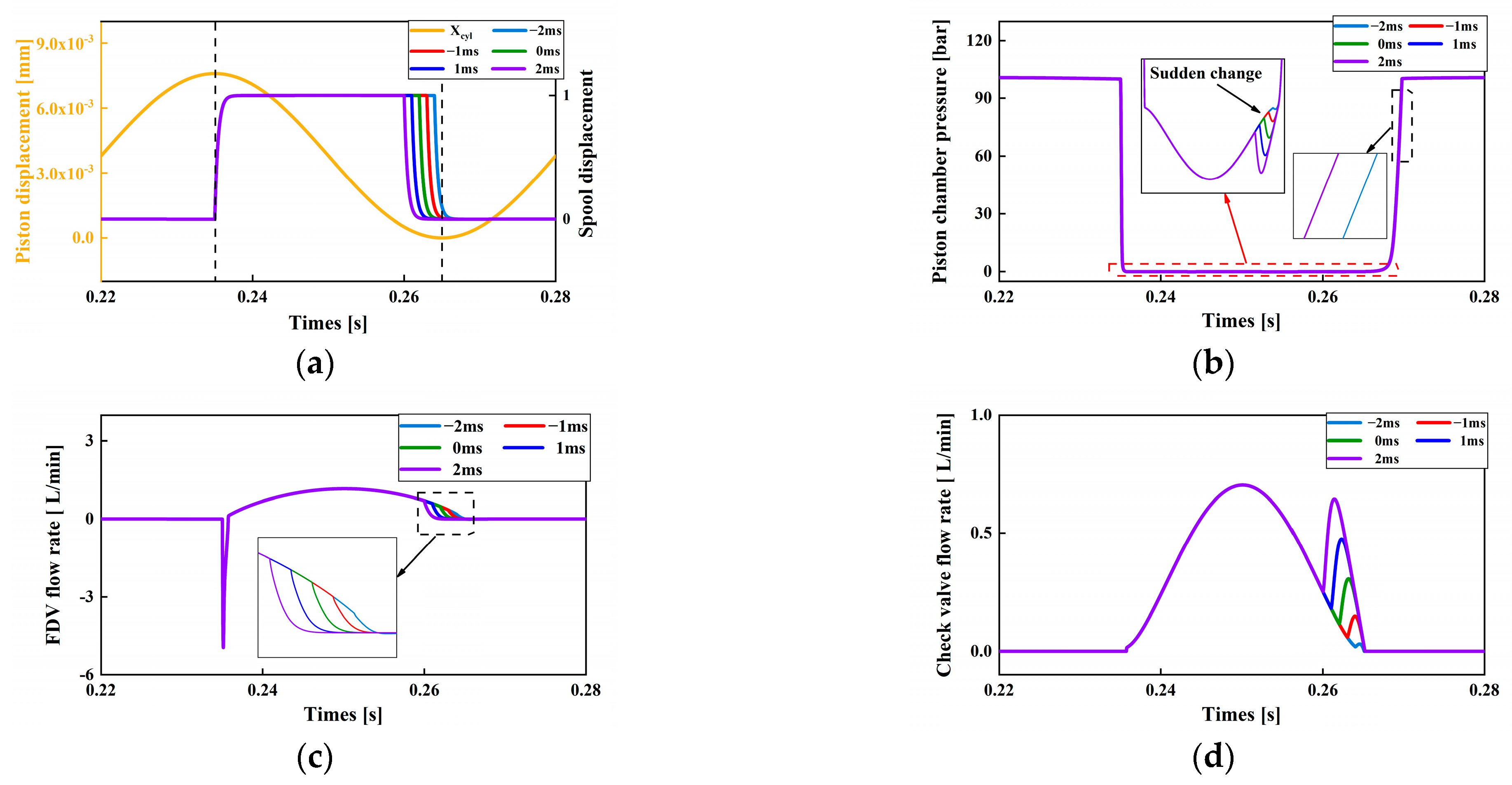
Figure 5 shows the main performance curves of the digital pump with T o c increasing.
From picture (a), as the T o c increases, the opening time of the FDV spool is transferred from the pumping stage to the suction stage. When T o c is −2 ms, the spool starts moving just at the TDC. It can be seen from picture (b) that the pressure of the piston chamber will fall to zero during at pumping stage with −4 ms, which reduces the output flow of the digital pump. On the contrary, when T o c is equal to 4 ms, the pressure of the piston chamber becomes negative because of the late opening of the FDV. According to the picture (c) and (d), the backflow amplitude gradually becomes smaller with the increase in the T o c . When T o c is greater than 2 ms, no backflow occurs. It can also be apparent that oversized T o c forces the FDV to open too late, which results in the sucking oil having to be executed by the auxiliary check valve.

4.2.2. Effects of the Tcc on the FDV

As shown in Figure 6a, the FDV began to close at different piston displacements with various T c c . When T c c is set to 2 ms, the FDV has been closed before the piston travels to the BDC. It can be found from pictures (c) and (d) that the FDV flow descends to zero at the last of the suction stage, and the flow through the auxiliary check valve is the highest correspondingly. Picture (b) shows that there is a sudden pressure reduction in the piston chamber due to the too-early closing of the FDV. The reason for this appearance is that the pressure difference with only the auxiliary check valve working is greater than the one of the simultaneous operation of the two valves. Moreover, we can see that the pressure rise of the piston chamber with T c c being −2ms lags behind the other. The pressure variation in the piston chamber is identical except for −2 ms because the auxiliary check valve can compensate for the shutting off of the FDV.

5. Adaptive Control of the FDV

5.1. Control Principle of Adaptive Control of the FDV

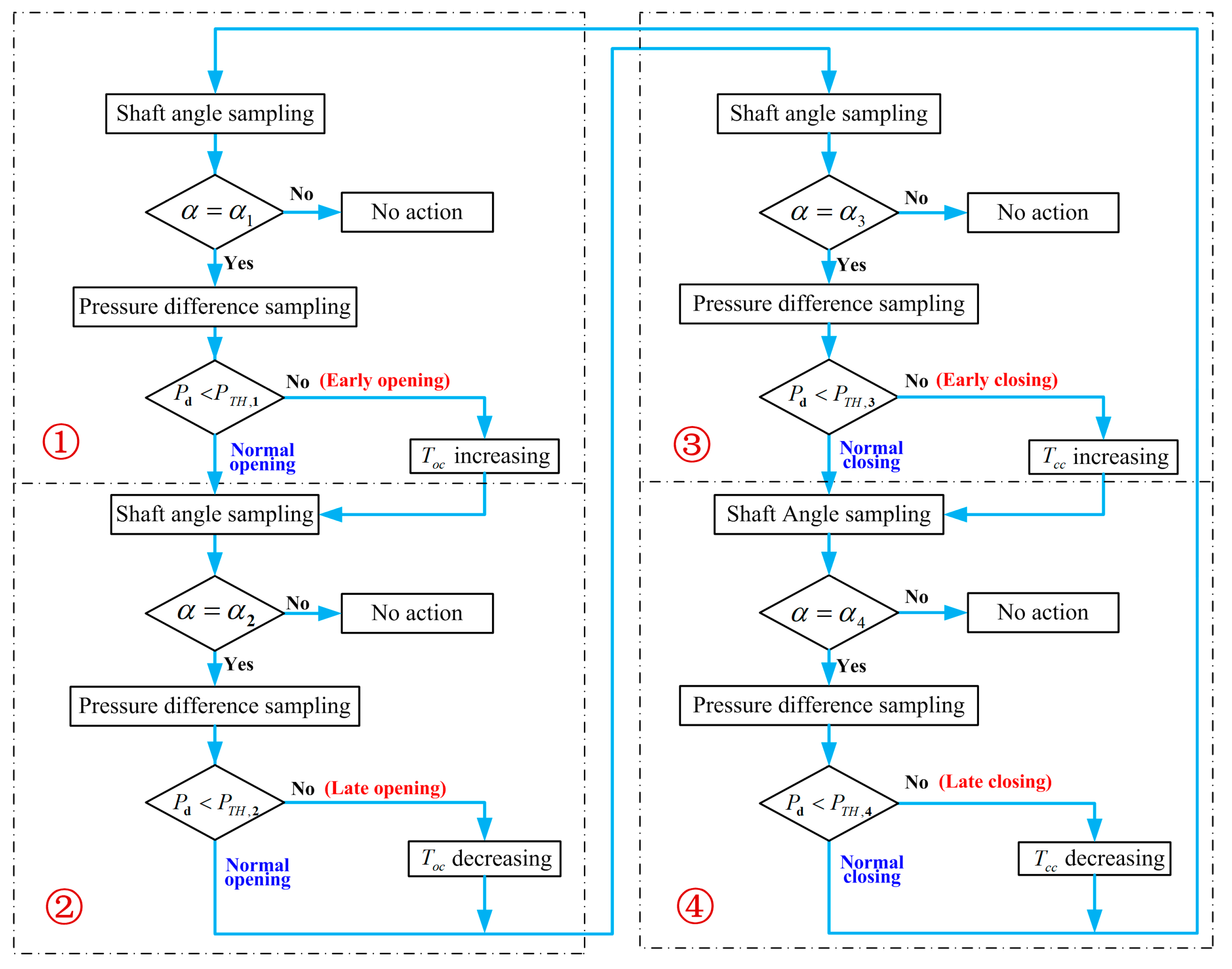
From the viewpoint of the producing mechanism of the backflow and the volumetric efficiency decrease, we propose an adaptive control method for the FDV of a digital pump, which detects the rotation angle of the digital pump shaft and the pressure difference between the inlet and outlet of the FDV. The flowchart of the adaptive control method is demonstrated in Figure 7.
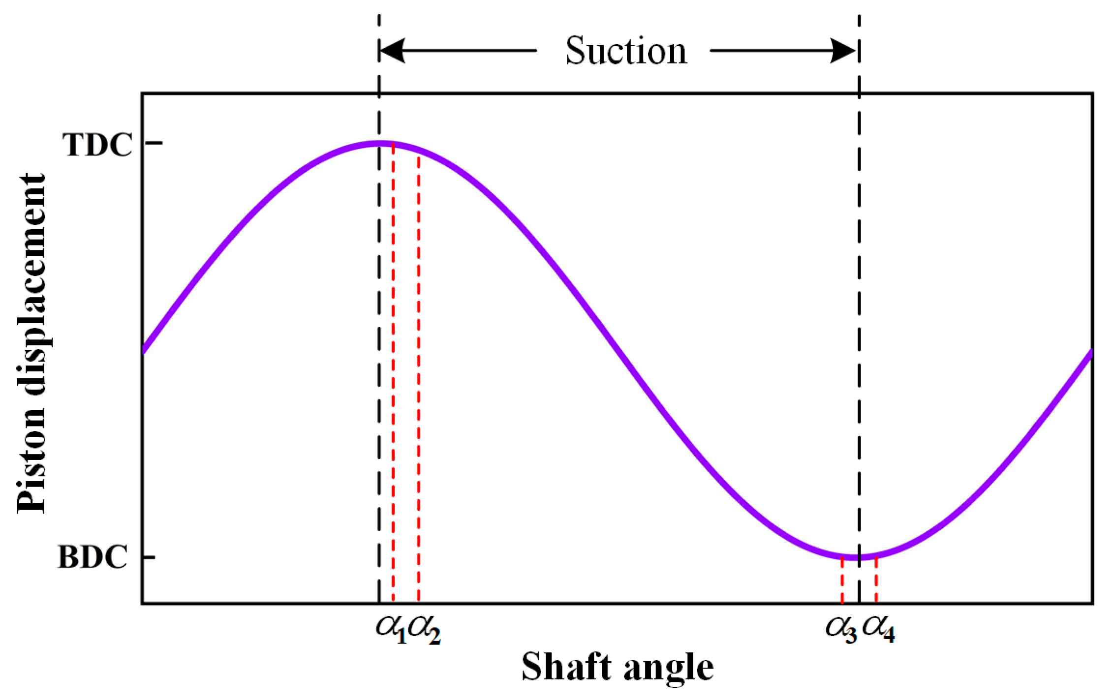
As can be seen from Figure 7, the whole adaptive control of the FDV is divided into four parts that are as follows: ① early opening handling module, ② late opening handling module, ③ early closing handling module, and ④ late closing handling module. These four modules are executed once in order when the pump shaft rotates by 360 degrees, which keeps the adaptive control operation of the FDV running and achieves the adaptive adjustment of the T o c and T c c . The adaptive control of the FDV has four important shaft angles α 1   , α 2 , α 3 , and α 4 , at which the early opening, late opening, early closing, and late closing are inspected, respectively. The locations of these four critical angles are represented in Figure 8.
The detailed control strategy of adaptive control of the FDV is described as follows.
  • In the early opening handling module, when the shaft angle collected by the rotary encoder is not equal to the early opening assessment angle α1. Nothing special has to be performed. Conversely, the pressure difference between the inlet and outlet of the FDV is sampled and compared with the set threshold PTH,1. If the pressure difference is greater than the threshold, the FDV is opening too early and the Toc is raised. According to Figure 5b, when the FDV is opening in advance, the pressure of the piston chamber is not as great as expected because the high-pressure oil in the piston chamber will be discharged through the FDV; on the contrary, the control of the FDV is normal, and the next module is subsequently called.
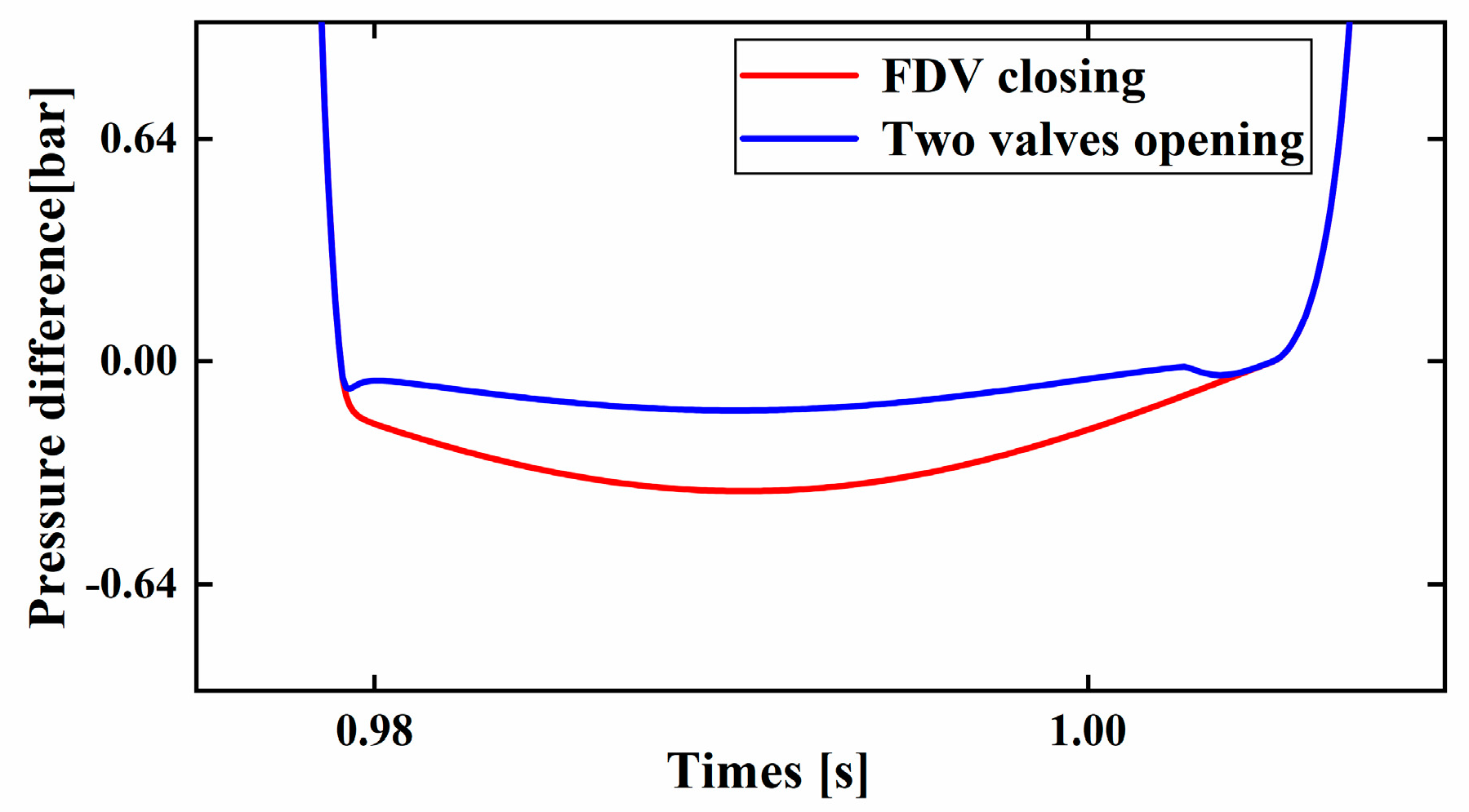
  • When the shaft of the digital pump is late opening assessment angle α2, the late opening of the FDV is detected and treated. If the FDV is not activated at α2, the oil enters the piston chamber only via the auxiliary check valve, and the pressure difference of the FDV is smaller than the one of the two valves opening. The pressure difference comparison of the FDV closing and the two valves opening is displayed in Figure 9. If the late opening of the FDV is perceived, the decrease in Toc is implemented.
  • The operating principle of adaptive control of the FDV early closing is similar to the late opening; the Tcc decreases when the FDV is prematurely deactivated. The comparison between Pd and PTH,3 and Tcc adjustment are both carried out with the shaft angle equaling to α3.
  • The solution to the late closing of the FDV is entirely consistent with the early opening handling module. If the FDV is not closed in time, the piston chamber is connected to the tank, and the pressure of the piston chamber can not rise to the threshold PTH,4 at the shaft angle α4. In this case, the Tcc is gradually increased to the early opening of the FDV.

5.2. Simulation Analysis of Adaptive Control of the FDV

5.2.1. The Results with Motor Speed Changes

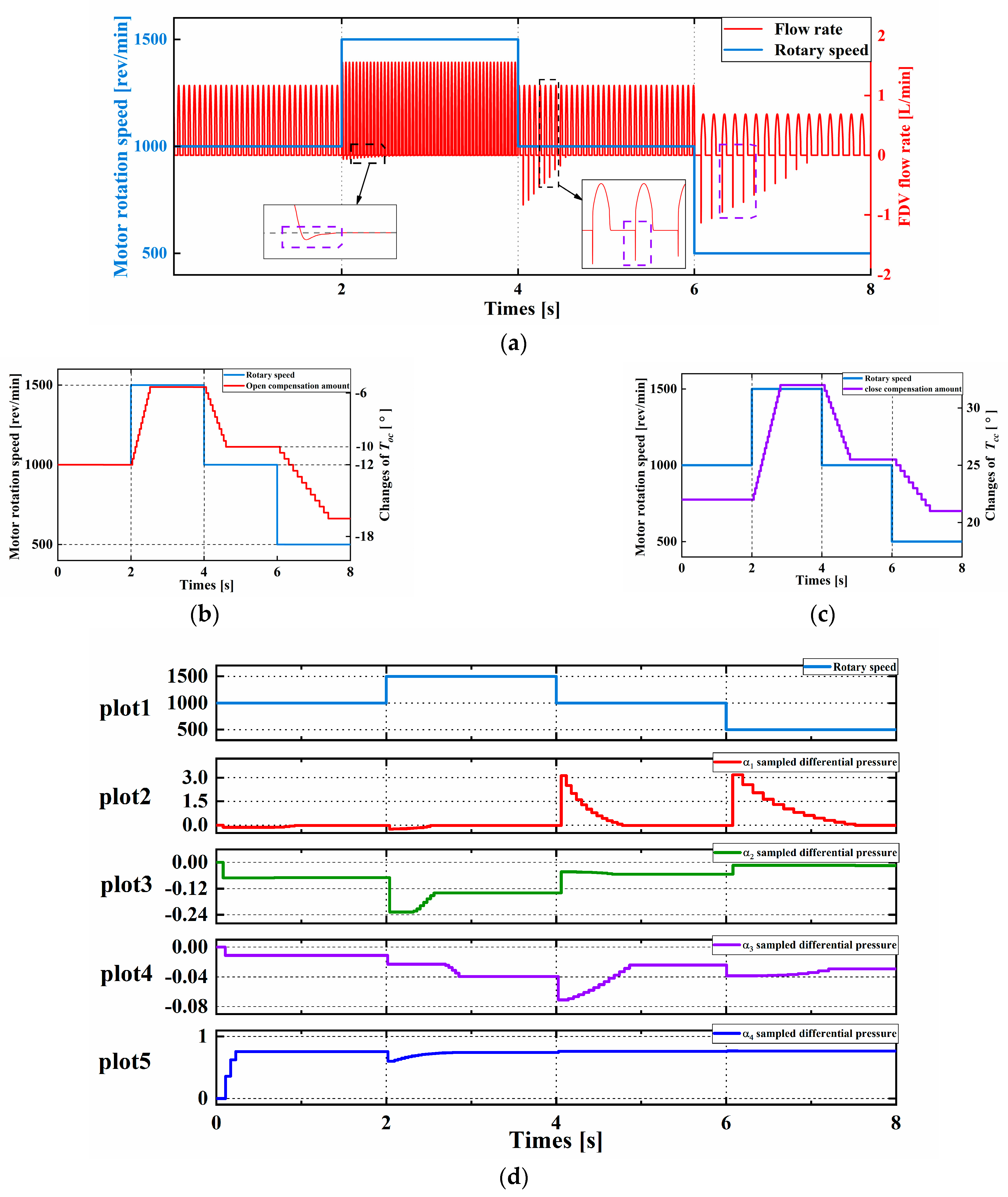
The step changes in moto speed are used to analyze and verify the effectiveness of the adaptive control method proposed in this paper. The flow rate of the FDV is shown in Figure 10a with motor speed fluctuations. It can be seen that the flow rate of the FDV is proportional to the motor speed, but the backflow of the FDV emerges after the motor speed variation. This phenomenon is weak when the motor speed step increases but stronger when the speed step decreases. The increase in motor speed means that the activation and inactivation of the FDV are performed; hence, there is a small amount of backflow at the moment of the FDV closing after 2 s. From pictures (b), (c), and (d), the T o c and T c c are automatically elevated from −12 to −6 and from −22 to −32 under adaptive control and kept in the optimum values related to the motor speed.
When the motor speed reduces by 500 r/min at 4 and 6 ms, a violent flow backward appears in the opening process of the FDV. In the timeline, the moment of action of the FDV does not change, but the movement of the plunger was delayed. It is obvious that the sudden reduction in the motor speed is equivalent to the early opening and closing of the FDV. According to the module 1 and 3 in Figure 7, the T o c and T c c should be diminished with the premature motion of the FDV, which can be proved by the curves reducing from −6 to −16 and from −32 to −21 between 4 and 8 ms in Figure 10b,c. Additionally, it can be seen from Figure 10d that this method can improve the situation of excessive pressure difference during FDV action. As a result, the adaptive control approach is better able to cope with the motor speed change, and the backflow phenomenon is eliminated.

5.2.2. The Results with the Different Dynamic Responses of the FDV

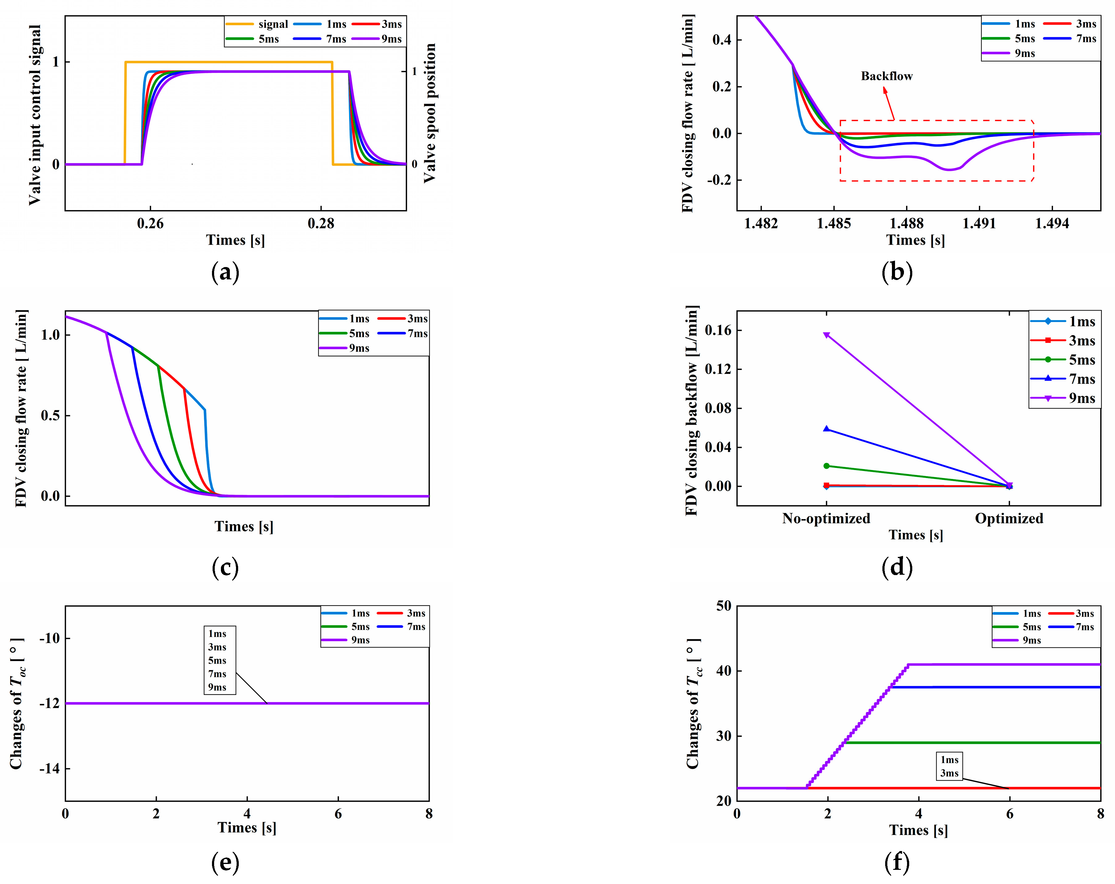
It is found from Figure 2 that the dynamic response of the FDV contains the delay and spool moving two parts. In this paper, the spool moving time of the FDV is altered to ascertain the availability of the adaptive control, the motor speed is set to 1000 rpm, and the delay time of the FDV is still held at the primitive value 2 ms. As shown in Figure 11a, the time spent by the spool moving varies from 1 ms to 9 ms. The initial phase is set so that the FDV is already in a perfect flow distribution when the spool starts moving in the opening stage. The time the spool starts to open and close has no change because the delay time and control signal of the FDV is invariant, which prevents the early or late opening of the FDV from happening. Hence, the value of T o c shown in Figure 11e is equivalent. The longer spool moving time may cause the complete closing of the FDV at the pumping stage of the digital pump, making more backflow, which can be observed in Figure 11b. Figure 11c shows the flow of the FDV closing process utilizing the adaptive control, and the backflow is completely removed. The backflow contrast curves of the FDV before and after optimization are unlocked in Figure 11d. When the closing moving time of the FDV is greater than 3 ms, the late closing trouble takes place and is solved by means of increasing T c c , which can be confirmed by the increase, respectively, from 22 to 29, 38, and 42 in Figure 11f.

6. Conclusions

In this paper, the self-adaption flow distribution of the digital pump with FDV and an auxiliary check valve is studied. Inappropriate control signal T o c and T c c generated by the changes in the FDV dynamic properties and motor speed will bring the early or late working of the FDV and lead to the backflow of oil in the piston chamber and more volumetric efficiency losses. As a consequence, T o c and T c c of the FDV must be corrected in real-time to avoid flow distribution errors.
A new adaptive control method for the FDV is proposed to automatically adjust the T o c and T c c and compensate for the inevitable undulation of the motor speed and the variation in FDV response. The approach suggested is completed by conducting four compares between the pressure difference sampled at the shaft angle α1, α2, α3, α4 with the pre-set thresholds.
The simulation results reveal that when the adaptive control is implemented, the T o c and T c c can be autonomously revised with the aforementioned changes, and the undesired backflow is cleaned up. The work in the future is the test rig development of the digital pump by utilizing the semi-physical simulation system in our laboratory and validating the availability of this solution through the experiment.

Author Contributions

Conceptualization, Y.L. and L.W.; methodology, L.W.; software, D.Y. and X.Z.; validation, D.Y., X.Z. and Z.L.; formal analysis, Y.L. and L.W.; investigation, Z.L. and Y.Z.; resources, L.W.; data curation, D.Y. and X.Z.; writing—original draft preparation, D.Y. and X.Z.; writing—review and editing, L.W. and Z.L.; visualization, X.Z.; supervision, Z.L.; project administration, Z.L.; funding acquisition, L.W. and D.Y. All authors have read and agreed to the published version of the manuscript.

Funding

This research was funded by the National Key R&D Program of China (Grant No. 2020YFB2009803).

Data Availability Statement

Not applicable.

Conflicts of Interest

The authors declared no potential conflict of interest with respect to the research, authorship, and publication of this article.

References

  1. Zhang, Q.W.; Kong, X.D.; Yu, B.; Ba, K.X.; Jin, Z.G.; Kang, Y. Review and Development Trend of Digital Hydraulic Technology. Appl. Sci. 2020, 10, 579. [Google Scholar] [CrossRef] [Green Version]
  2. Danfoss. Data Sheet-Digital Displacement® Pump DDP096 and DPC12. 2022. Available online: https://www.bibus.sk/fileadmin/editors/countries/bibsk/Suppliers/Danfoss/documents/displacement-pumps/danfoss-DOC332065464017.pdf (accessed on 30 December 2019).
  3. Zhao, J.; Wang, M.; Wang, Z.; Grekhov, L.; Qiu, T.; Ma, X.J.A.T.E. Different boost voltage effects on the dynamic response and energy losses of high-speed solenoid valves. Appl. Therm. Eng. 2017, 123, 1494–1503. [Google Scholar] [CrossRef]
  4. Zhao, J.; Yue, P.; Grekhov, L.; Ma, X.J.A.T.E. Hold current effects on the power losses of high-speed solenoid valve for common-rail injector. Appl. Therm. Eng. 2018, 128, 1579–1587. [Google Scholar] [CrossRef]
  5. Su, M. Investigation on Control Characteristics and Method of Solenoid High Speed on/off Valve. Ph.D. Thesis, Guizhou University, Guiyang, China, 2010. [Google Scholar]
  6. Gao, Q.; Zhu, Y.; Luo, Z.; Bruno, N. Investigation on adaptive pulse width modulation control for high speed on/off valve. J. Mech. Sci. Technol. 2020, 34, 1711–1722. [Google Scholar] [CrossRef]
  7. Zhong, Q. Research on Control Algorithm for High-speed on/off Valves that Adaptive to Supply Pressure Changes. J. Mech. Eng. 2021, 57, 224–235. [Google Scholar]
  8. Zhong, Q. Performance Analysis of High Speed on/off Valve by Multi-voltages Compound Excitation. J. Mech. Eng. 2021, 57, 191–201. [Google Scholar]
  9. Chapple, P.; Lindholdt, P.N.; Larsen, H.B. An Approach to Digital Distributor Valves in Low Speed Pumps and Motors. In Proceedings of the ASME/BATH 2014 Symposium on Fluid Power and Motion Control, Bath, United Kingdom, 10–12 September 2014. [Google Scholar]
  10. Yue, D.; Li, L.; Wei, L.; Liu, Z.; Liu, C.; Zuo, X. Effects of Pulse Voltage Duration on Open–Close Dynamic Characteristics of Solenoid Screw-In Cartridge Valves. Processes 2021, 9, 1722. [Google Scholar] [CrossRef]
  11. Liu, Z.; Li, L.; Yue, D.; Wei, L.; Liu, C.; Zuo, X. Dynamic Performance Improvement of Solenoid Screw-In Cartridge Valve Using a New Hybrid Voltage Control. Machines 2022, 10, 106. [Google Scholar] [CrossRef]
  12. Pan, J.; Shi, G. Distribution Characteristics of Hydraulic Motor with Digital Distribution. Trans. Chin. Soc. Agric. Mach. 2011, 42, 203–208. [Google Scholar]
  13. Pedersen, N.H.; Johansen, P.; Andersen, T.O. Feedback Control of Pulse-Density-Modulated Digital Displacement Transmission Using a Continuous Approximation. IEEE/ASME Trans. Mechatron. 2020, 25, 2472–2482. [Google Scholar] [CrossRef]
  14. Pedersen, N.H.; Johansen, P.; Andersen, T.O. Four Quadrant Hybrid Control Oriented Dynamical System Model of Digital Displacement (R) Units. In Fluid Power Systems Technology; American Society of Mechanical Engineers: New York, NY, USA, 2018. [Google Scholar]
  15. Pedersen, N.H.; Johansen, P.; Andersen, T.O. Model Predictive Control and Discrete Analysis of Partial Stroke Operated Digital Displacement Unit. In 2018 Global Fluid Power Society Phd Symposium (Gfps); IEEE: Piscataway, NJ, USA, 2018. [Google Scholar]
  16. Pedersen, N.H.; Johansen, P.; Andersen, T.O. Event-Driven Control of a Speed Varying Digital Displacement Machine. In Proceedings of the Asme/Bath Symposium on Fluid Power and Motion Control, Sarasota, FL, USA, 16–19 October 2017. [Google Scholar]
  17. El-Breidi, F. Investigation of Digital Pump/Motor Control Strategies; Purdue University: West Lafayette, Indiana, 2016. [Google Scholar]
  18. Breidi, F.; Garrity, J.; Lumkes, J., Jr. Investigation of a Real-Time Pressure Based Valve Timing Correction Algorithm. In Proceedings of the ASME/BATH 2017 Symposium on Fluid Power and Motion Control, Sarasota, FL, USA, 16–19 October 2017. [Google Scholar]
  19. Nordas, S.; Beck, M.M.; Ebbesen, M.K.; Andersen, T.O. Dynamic Response of a Digital Displacement Motor Operating with Various Displacement Strategies. Energies 2019, 12, 1737. [Google Scholar] [CrossRef] [Green Version]
  20. Tian, H.; Li, P.Y.; Van de Ven, J.D. Valve Timing Control for a Digital Displacement Hydraulic Motor Using an Angle-Domain Repetitive Controller. IEEE/ASME Trans. Mechatron. 2019, 24, 1306–1315. [Google Scholar] [CrossRef]
  21. Darnet, J.; Bideaux, É. State-of-the-art of Variable Displacement Technologies for Radial Piston Hydraulic Machines. In Proceedings of the Asme/Bath Symposium on Fluid Power and Motion Control, Bath, UK, 14–16 September 2022. [Google Scholar]
  22. Pedersen, N.H.; Johansen, P.; Andersen, T.O. Lqr Feedback Control Development for Wind Turbines Featuring a Digital Fluid Power Transmission System. In Proceedings of the 9th Fpni Ph.D Symposium on Fluid Power, Florianópolis, SC, Brazil, 26–28 October 2016. [Google Scholar]
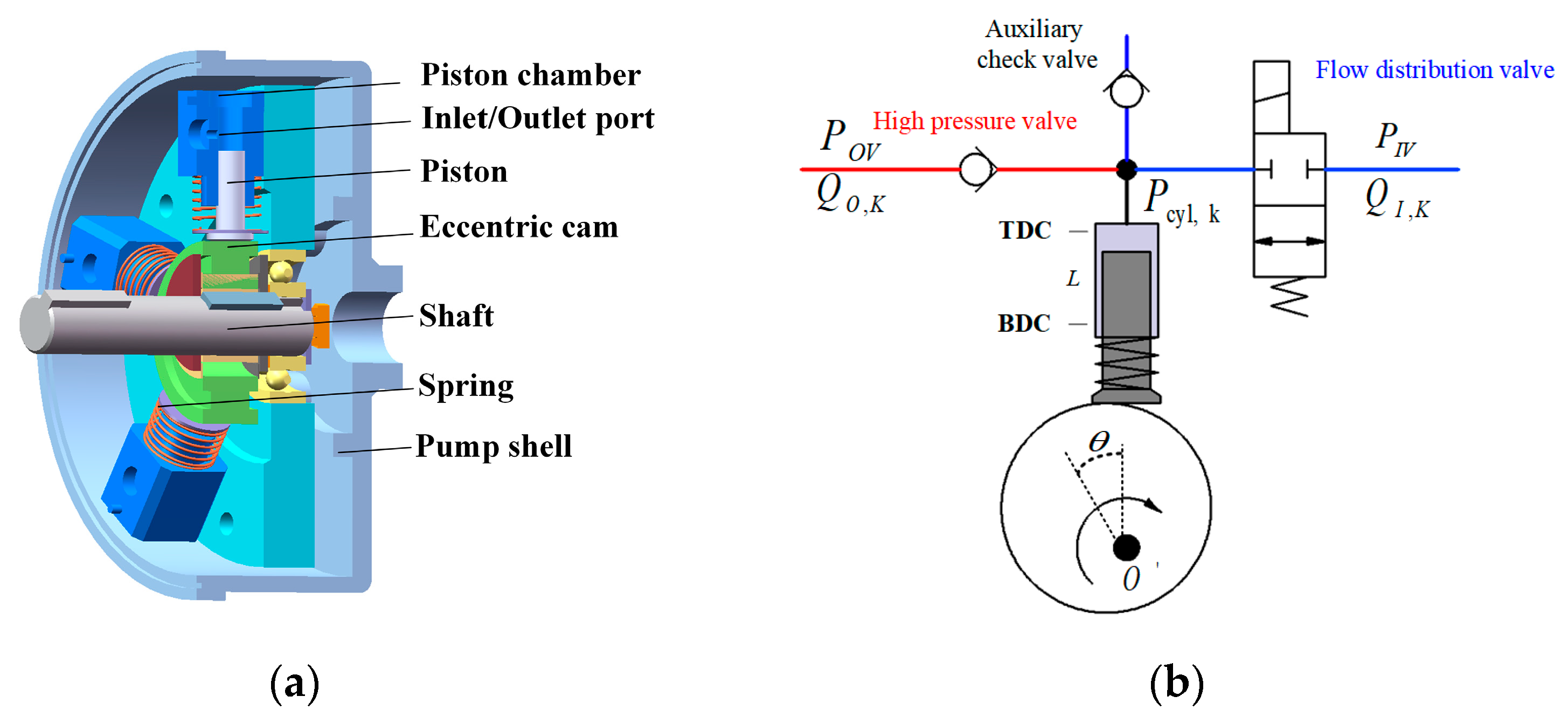
Figure 1. Structure and working principle: (a) Structural section drawing; (b) flow distribution principle.
Machines 11 00148 g001
Figure 2. FDV dynamics response characteristic: ①: the spool opening delay stage; ②: the spool opening moving stage; ③: holding opening stage; ④: the spool closing delay stage; ⑤: the spool closing moving stage.
Machines 11 00148 g002
Figure 3. Perfect flow distribution state: plot 1: rotational angle; plot 2: Piston displacement; plot 3: The spool position and control signal; plot 4: FDV and HPV flow rate.
Machines 11 00148 g003
Figure 4. Simulation model of the digital pump.
Machines 11 00148 g004
Figure 5. Characteristics with different Toc: (a) spool displacement; (b) piston chamber pressure; (c) FDV flow rate; (d) auxiliary check valve flow rate.
Machines 11 00148 g005
Figure 6. Characteristics with different Tcc: (a) spool displacement; (b) piston chamber pressure; (c) FDV flow rate; (d) auxiliary check valve flow rate.
Machines 11 00148 g006
Figure 7. The flow chart for adaptive control of the FDV.
Machines 11 00148 g007
Figure 8. The diagram of the inspection angles of flow distribution.
Machines 11 00148 g008
Figure 9. Pressure difference comparison of FDV closing and two valves opening.
Machines 11 00148 g009
Figure 10. The results with different motor speeds: (a) flow rate of FDV; (b) Toc curve; (c) Tcc curve; (d) plot 1: Motor speed; plot 2–4: differential pressure at α1, α2, α3, α4.
Machines 11 00148 g010
Figure 11. The results of different dynamic characteristics of FDV: (a) spool displacement; (b) flow rate before optimization; (c) optimized flow rate; (d) comparison backflow of FDV closing process; (e) Toc curve; (f) Tcc curve.
Machines 11 00148 g011
Table 1. Main performance parameters.
ParameterValueUnit
Pump angular speed1000rpm
The radius of the eccentric31mm
Piston diameter10mm
Eccentricity3.8mm
Flow coefficient0.7
Dead volume of piston0.08mm3
Chamber length 25.1mm
FDV dynamic response5ms
Toc2ms
Tcc5ms
Disclaimer/Publisher’s Note: The statements, opinions and data contained in all publications are solely those of the individual author(s) and contributor(s) and not of MDPI and/or the editor(s). MDPI and/or the editor(s) disclaim responsibility for any injury to people or property resulting from any ideas, methods, instructions or products referred to in the content.