Abstract
The application of C/C composites in finger seals can effectively solve the problem of seal wear due to its excellent tribological and mechanical behaviors. However, the designable characteristics of composites, such as the density and orientation of fabric on the friction plane, have a very important influence on the tribological properties and service life of sealing materials. In order to obtain a better material design scheme for the C/C composite on the finger seal, it is necessary to conduct research on the tribological properties and wear mechanism of the C/C composite based on the working conditions of the finger seal. Therefore, a reciprocating tribo-tester was used to conduct the test by abrading the C/C composite disk with a pin made of 1045,080M46. The effects of material density, fabric orientation, and load and sliding velocity on the tribological properties and wear mechanism of the C/C composite were studied. The results show that the friction coefficient and wear rate of the composite with a perpendicular orientation (non-woven cloth perpendicular to the friction plane) were lower than those with a parallel orientation (non-woven cloth parallel to the friction plane). The tribological properties with higher density are better than those of material with a lower density. The friction coefficient of low-density material increases with the load, whereas it decreases gradually with high-density material. The wear rate increases with the load for two-density materials. With the increase in the sliding velocity, the friction coefficient decreases. The wear rate of low-density material decreases significantly, whereas it changes little with high-density material. The influence of the sliding velocity on the friction and wear properties of the C/C composite is greater than that of the load. This study provides a feasible material design idea for effectively alleviating the wear of finger seals.
1. Introduction
The finger seal was developed as an advanced sealing technique after labyrinth and brush seals, and it has the potential application prospect in gas sealing and bearing chamber sealing in aeroengines [1,2]. The seal and the rotor contact each other, and the sealing interface that is formed limits the fluid percolation through the gap between the two contacting solids. Seal leakage is a critical characteristic of the seal apparatus as well as the aero-engine, which is affected by the contact topology and surface roughness characteristics [3,4,5]. For finger seals, increasing the contact pressure of the seal interface by increasing the seal stiffness can effectively reduce leakage, but at the same time, it will increase seal wear and reduce service life. When the seal configuration is designed reasonably, the performance of the friction pair components formed by the seal and the rotor is an important factor in affecting the reliability of the seal. Among them, the characteristics of the sealing material become one of the decisive factors for the finger seal system to achieve the expected goals. Finger seals that are now available are mainly made of cobalt-base alloys, and the sealing performance is improved in a limited range due to the restriction of the design space of the finger structure [6,7]. Therefore, it is a worthwhile way to explore and improve sealing performance from the perspective of seal material design.
Carbon fiber has good mechanical and tribological properties, which is of great significance for increasing wear resistance and improving the mechanical properties of materials [8]. Kaya [9] investigated the effects of the fabric orientation on the tribological behavior of carbon fiber-reinforced epoxy composite and discovered that the anti-parallel and parallel direction-oriented fiber specimens gave lower friction coefficient values.
In many carbon fiber reinforced composites, C/C (carbon fiber reinforced carbon matrix) composites have become the preferred solution for the braking materials of aircraft, high-speed trains, etc, due to their low density, high strength, and excellent thermal and friction and wear properties [10]. Li [11] studied the wear behavior of C/C composites under braking conditions and obtained that the wear rate of the material decreased with the increasing initial braking speed. Shpenev [12] pointed out that the material based on graphite fibers has double wear resistance, and this can be used to increase the service life of aircraft brakes. Wang [13] investigated the friction and wear properties of the two C/C composites under varied braking conditions. Carbon brake discs with high performance can be obtained by controlling the process parameters, including the carbon fiber performance, densification process, high-temperature treatment process, etc. [14].
In addition to the braking field, C/C composites have also been widely used in other engineering fields due to their excellent tribological and mechanical behaviors, such as seals [15]. In order to apply C/C composites to the finger seal, it is very important to correctly and systematically understand the tribological properties and wear mechanism of C/C composites under sealing environments. The tribological test is the most direct and reliable method. However, researchers have carried out many tribological tests on C/C composites, most of which are based on the background of brake discs [16,17]. It is shown that the type of preform, the type of matrix carbon, fabric orientation, and working environment conditions (humidity, speed, load) of C/C composites have a great impact on the friction and wear properties of the materials [18,19,20]. Fu [21] tested the C/C composites under different lubricating conditions and found that a complete and smooth wear debris film could be formed, and material loss was minimum under dry conditions compared with the results under water and oil situations.
Most works now available focus on the heavy load conditions based on the brake disc application, and the experimental research on the C/C composite with light load application conditions for the finger seal is less. Zhang [22] tested the pins with two different materials and discs with two different coatings and found that the C/C-Cr3C2 pair had the greatest friction characteristics and least wear loss for finger seal application. Su [23] carried out a pin-on-disk high-temperature friction and wear test to study the tribological behavior between the pair of C/C composites and 40CrNiMoA under different working conditions. Additionally, the relationship between the wear rate and working conditions was described mathematically.
In the existing works, the load conditions of the C/C composite tribological test for finger seal application were designed by the average pressure between the finger seal and the rotor extracted from structural finite element analysis. However, the finger seal actually contacts locally with the rotor and the wear is also local and uneven on the actual friction surface, so it is more effective to consider the actual contact pressure between the finger seal, and the rotor [24,25]. In order to meet the needs of finger seal application, friction and wear tests of the C/C composites were carried out to analyze the effects of material density, fabric orientation, working load, and sliding velocity on the friction coefficient and wear rate of the composite. The wear mechanism was revealed by adopting scanning electron microscopy (SEM). This study could provide a feasible material design idea and technical support for the selection and design of C/C composites applied in the finger seal.
2. Experimental Details
2.1. Geometric Structure of Finger Seal
The finger seal structure is illustrated in Figure 1. One finger sheet element (Figure 1a) is machined by a circular annular sheet, which comprises a series of flexible curved finger sticks. There are gaps between the adjacent finger sticks to make the flexible finger sticks follow the rotor’s motion better. Several finger sheet elements are sandwiched (Figure 1b) by rotating one finger sheet element relative to its adjacent element in order to make each finger stick cover the gap of its adjacent element. Finger elements are clamped by the forward plate and back plate and fixed with rivets at the solid annulus.
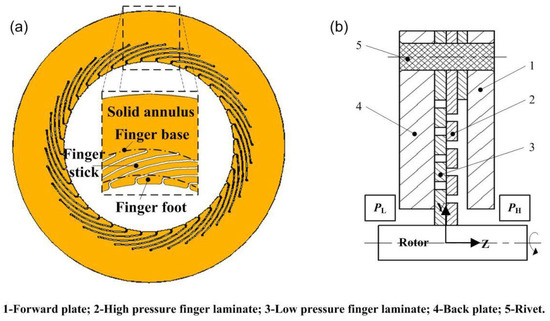
Figure 1.
Geometric structure of finger seal.
During operation, the rotor has a radial runout due to centrifugal action, and the finger foot of the seal is in contact with the rotor to limit the flow and leakage of high-pressure gas (high-pressure PH) to the low-pressure chamber (low-pressure PL). Therefore, there is a pressure differential from the high to the low-pressure chamber in the axial direction of the seal. Because the rotor contacts and slides with the seal, the problem of friction and wear are inevitable. The finger seal involved in this study adopts the C/C composite. In order to simulate the friction and wear properties and mechanism of C/C composites under finger seal conditions, it is necessary to conduct a tribological test of C/C composites in the following work.
2.2. Materials
The C/C composite disk sliding against the steel pin was used in the tribological test. The preparation process of the C/C composite is as follows (Figure 2) [26]. PAN-based carbon fiber (T700) was used, with each yarn containing 12,000 filaments. The C/C composite preform was manufactured and prepared by laminating the 0° carbon non-woven cloth (unidirectional carbon fabric), 90° carbon non-woven cloth, and the carbon felt (short fibers) and then needling in the laminated direction. Each carbon fiber unit (carbon non-woven cloth and carbon felt) had a thickness of about 0.5~0.8 mm. This kind of preform matches the good in-plane properties of 2D composites and the high delamination resistance of multidirectional composites. The preform was densified to 1.5–1.6 g/cm3 by chemical vapor deposition and then densified to the required densities (1.80–1.85 g/cm3) by liquid phase furan resin impregnation and carbonization. The prepared C/C composite was then cut to form a disk sample with a friction surface size of 30 mm × 20 mm, with a thickness of 3 mm. The counterpart material is a pin (Φ2 mm × 8 mm) made of 1045,080M46 (ASTM standards).
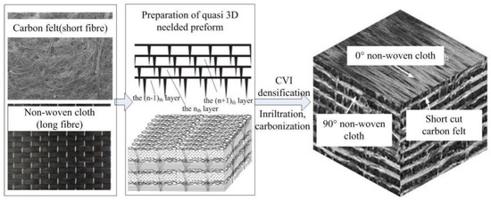
Figure 2.
Schematic of preparation for C/C composites.
The relationship between the fabric orientation of the C/C composite, the friction plane, and the sliding direction is described as follows (Figure 3). According to the structural characteristics of C/C composite preforms, the friction plane is designed as two arrangements. One is that the friction plane is perpendicular to the non-woven cloth, called perpendicular orientation. The other is that the friction plane is parallel to the non-woven cloth, called parallel orientation.
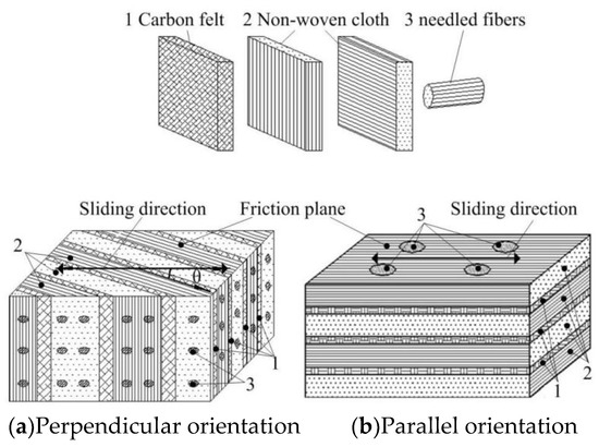
Figure 3.
Schematic of the fabric orientation with respect to sliding direction.
It was noted that the connection strength between the non-woven cloths of the C/C composite was low. In addition, the finger seal generally worked under a certain axial gas pressure differential, and the sliding direction between the finger seal and the rotor was perpendicular to the axial direction of the seal [26]. This made the friction and wear tests of the C/C composite based on the application background of the finger seal require that the friction plane be perpendicular to the non-woven cloth in order to avoid the risk of delamination, as shown in Figure 3a. Therefore, this orientation design is used to simulate the abrading interaction between finger seal laminates and the rotor under different working conditions in machinery. The orientation angle between the sliding direction and the non-woven cloth is expressed by θ (0~π/2).
2.3. Experimental Methods
Based on the ASTM G99-04 test method of the pin-on-disk friction test, a reciprocating tribological tester was used to conduct the sliding friction and wear test, as shown in Figure 4. The testing machine consists of the main frame, upper sample motion unit, upper sample fixture, lower sample motor unit, and the force sensor. Before the test, the friction surface of the C/C composite disk was polished by using 800# waterproof abrasive paper, and the steel pin was also processed by pre-grinding against the abrasive paper for 5 min. The contact surface roughness of the C/C composite disk and steel pin was 3.2 μm. The samples were de-greased with acetone to calibrate their initial state. Then, the C/C composite disk sample adhered to the lower sample table. After the tester was started, the loading parameters and motion parameters were set through the computer software control panel. The servo mechanical system drives the upper sample module and completes loading, and controls the reciprocating motion of the lower sample drive module. The test was performed for 3600 s. During the test, the steel pin sample was fixed, and the C/C composite disk sample moved linearly with a reciprocating distance of 12 mm.
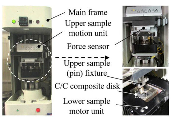
Figure 4.
Reciprocating pin-on-disk tribological tester.
The single-factor experiment was conducted as follows. The sliding velocity of test v ranged from 48 to 192 mm/s (the frequency is 4~16 Hz). Based on the finite element method in reference [27], the actual contact pressure between the finger seal and the rotor was obtained, and the load range of the pin-on-disk was determined from 10 to 70 N. It was aimed to study samples with densities of 1.80 and 1.85 g/cm3. The friction coefficient and wear rate under different fabric orientations, loads, and sliding velocities were measured, respectively. The friction coefficient is the ratio of the friction force to the normal pressure measured by the force sensor on the tester. The wear rate refers to the material wear volume under the unit sliding distance and unit load, and the unit is mm3/(Nm). For the C/C composite disk sample, the volume of the wear scar was measured by the profile method. A three-dimensional surface profiler (Surf Nanofocus AG) was used to measure the profile at three positions on the wear scar, and the profile was integrated to obtain the average cross-sectional area of the three points. Additionally, the wear volume was then calculated. After the test, the wear scar was observed by scanning electron microscope (SEM), and the friction and wear mechanism was analyzed.
3. Results
3.1. Effect of Material Density and Fabric Orientation on Friction and Wear Properties
Figure 5 and Figure 6 show the friction coefficient and wear rate of the C/C composite under varied fabric orientations with the material density held at 1.80 g/cm3 and 1.85 g/cm3, respectively. The samples with different fabric orientations in the test are marked and described as follows. When the non-woven cloth is parallel to the friction plane, it is marked as a 1# orientation. When the non-woven cloth is perpendicular to the friction plane, and the angles with the sliding direction are 0, π/4, and π/2, they are marked as 2#, 3#, and 4# orientations, respectively.
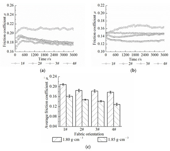
Figure 5.
Effect of material density and fabric orientation on friction coefficient. (a) 1.80 g·cm−3; (b) 1.85 g·cm−3; (c) Average friction coefficient.
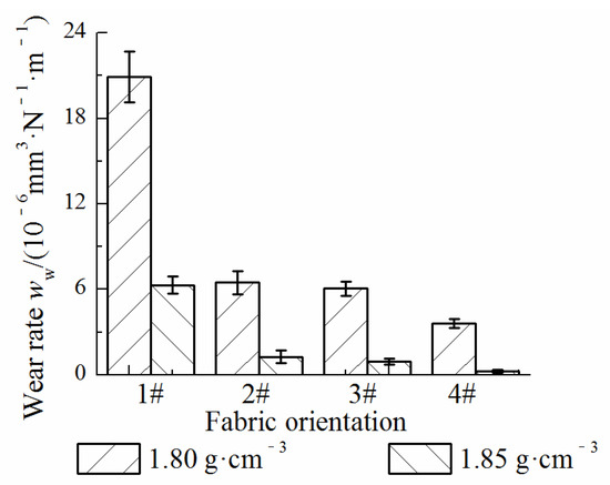
Figure 6.
Effect of material density and fabric orientation on wear rate.
When the material density is 1.80 g/cm3, the friction coefficient with a 1# orientation fluctuates slightly and has the largest value, while the initial value of the friction coefficient with 2#, 3#, and 4# orientations is larger and then gradually decreases and tends to be stable, and the difference also gradually decreases. For the higher material density (1.85 g/cm3), the friction coefficient with a 1# orientation fluctuates greatly and has the largest value, and it changes slightly and is lower with 2#, 3#, and 4# orientations. In addition, the friction coefficient with a 4# orientation is lower than that of materials with 2# and 3# orientations. It can be seen that the average friction coefficient of the material with a higher density is lower than that of the material with a lower density. The wear rates of materials with different orientations are in the order of 1# > 2# > 3# > 4#, among which the wear rates of materials with 2#, 3#, and 4# orientations are similar. Under the same fabric orientation, the wear rate of the material with a density of 1.85 g/cm3 was lower than that of the material with a density of 1.80 g/cm3.
Since the non-woven cloth of material with a 1# orientation was parallel to the friction plane, the overlapping of fibers meant that it was easy to form uneven rough surfaces and pores. During the friction process, the micro convex peaks are embedded into each other, which leads to an increase in the friction force, and the friction coefficient is larger than that of 2#, 3#, and 4# oriented materials. For the perpendicular orientations (2#, 3#, and 4#), non-woven cloth that is perpendicular to the friction plane plays a major role in bearing the load. The toughness and longitudinal strength of the fiber are higher, which makes it more difficult to shear fracture. The wear resistance of the fiber is better than that of the 1# oriented material. However, when the non-woven cloth is perpendicular to the friction plane, with the increase in the fabric orientation angle, the 4# orientation (θ = π/2) has the lowest wear rate, and the 2# orientation (θ = 0) has the highest wear rate. Although the direction of the non-woven cloth of the 2# oriented material is the same as the sliding direction, it is theoretically more conducive to increasing the wear resistance than the 4# oriented material. The opposite trend of the test results was due to the following reasons. The material with a 4# fabric orientation first appeared as a fiber fracture and generated more wear debris, which passivated the wear particles and alleviated wear. In addition, the C/C composite with a higher density was easier to form a complete transfer film with and had good friction and wear properties because of the higher connection strength between the fiber and matrix, a smaller number of pores, and a smoother surface.
3.2. Effect of Working Condition on Friction and Wear Properties
Considering that the 2#, 3#, and 4# oriented materials have similar friction and wear properties and based on the application background of the C/C composite in the finger seal, the effect of the load and sliding velocity on tribological properties of the material with a 2# orientation is analyzed.
The effects of the load on the dynamic friction coefficient, average friction coefficient, and wear rate of the material are shown in Figure 7 and Figure 8. It shows that the dynamic friction coefficient of the material with a density of 1.80 g/cm3 (Figure 7a) increased greatly under 10 N, while the coefficient tended to be stable and fluctuated slightly under 30 N, 50 N, and 70 N. When the load was low, the size of the wear debris formed by the deformation and fracture of the micro convex peak was large, resulting in furrows on the friction surface. This led to an increase in the friction force. In addition, the wear debris could not be fully compressed to form a complete friction film with the self-lubricating effect under low load conditions so that the friction coefficient could gradually increase with time. When the material density was 1.85 g/cm3(Figure 7b), the dynamic friction coefficient under 10 N rose and then reached stability. The friction coefficient under other load conditions had little difference compared with that of the material with low-density conditions. Because the surface of the material with a higher density was relatively flat and the pores were small, the fluctuation amplitude of the friction coefficient with time under low load conditions was small. It can be seen from Figure 7c that the influence of the load on the friction coefficient of a material with different densities is not the same. It is shown that the friction coefficient of low-density material increases with the load and fluctuates with an amplitude, while the friction coefficient of high-density material decreases gradually. It can be noted that the wear rates of materials under the two densities increase with the load, and this trend is more significant for low-density materials.
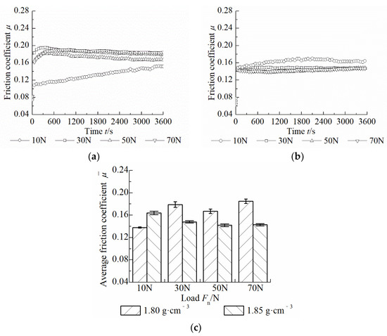
Figure 7.
Effect of load on friction coefficient. (a) 1.80 g·cm−3; (b) 1.85 g·cm−3; (c) Average friction coefficient.
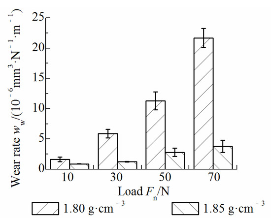
Figure 8.
Effect of load on wear rate.
Due to the large porosity and poor flatness of the material surface with a low density and the increase in the load, the friction surface asperities are embedded deeper, and the actual contact area increases. The friction force also increases, and the friction shear effect is enhanced, so the friction coefficient increases and the material wear is more serious. In contrast, the friction surface of the high-density material is more flat and dense, and the micro convex peaks are embedded shallowly. However, when the load is 10 N, the friction coefficient of the high-density material is higher than that of the low-density material. This is because neither of the two materials has suffered extensive wear and damage. The friction surface of the low-density material is easy to peel off and be compressed to form a transfer film. The film plays a self-lubricating role and makes the friction coefficient smaller than that of the high-density material.
The effects of the sliding velocity on the friction coefficient and wear rate of C/C composites with two densities are shown in Figure 9 and Figure 10. The dynamic friction coefficients of materials with two densities are the highest at the sliding velocity of 48 mm/s. At 96 mm/s, 144 mm/s, and 192 mm/s, the dynamic friction coefficient of the material with a low density (1.80 g/cm3) gradually decreases with time and tends to be stable, and decreases with the increase in the sliding velocity. The dynamic friction coefficient of the material with a high density (1.85 g/cm3) fluctuates slightly with time and tends to be consistent with the velocity varied from 96 mm/s to 192 mm/s. Figure 9c shows that the friction coefficient decreases with the increase in the sliding velocity. It can be seen from Figure 10 that the wear rate of the low-density material decreases significantly, while the wear rate of the high-density material decreases first and then tends to be stable. Compared with the effect of the load on the wear rate of the material, the effect of sliding velocity on the wear rate is much smaller.
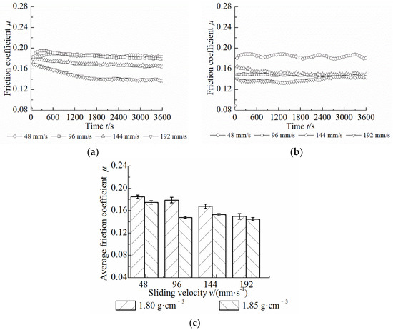
Figure 9.
Effect of sliding velocity on friction coefficient. (a) 1.80 g·cm−3; (b) 1.85 g·cm−3; (c) Average friction coefficient.
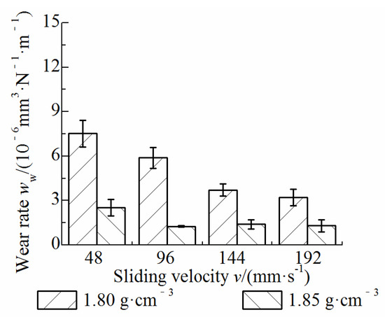
Figure 10.
Effect of sliding velocity on wear rate.
4. Discussion
Compared with 1# orientation, 2#, 3#, and 4# orientated materials have similar tribological properties. Thus, the friction and wear mechanisms of 1# and 2# oriented materials are analyzed according to the SEM photos shown in Figure 11. For the material with a density of 1.80 g/cm3, the non-woven cloth of the 1# orientated material is parallel to the friction plane, so the destruction of the transfer film leads to the exposure and consumption of a large number of fibers, which aggravates the wear (Figure 11a). However, the friction film formed by the 2# oriented material is relatively flat, with less wear (Figure 11b). For the 1# oriented material, because a large number of fibers parallel to the friction plane are sheared under the action of the friction force to form large particles of wear debris, which cause abrasive wear on the surface with poor surface smoothness and an obvious furrow effect, the friction coefficient and wear rate are large. However, the 2# oriented material has a higher carbon fiber content in the direction perpendicular to the friction plane than the 1# oriented material, and the fiber layer perpendicular to the friction plane plays a major role in bearing and has strong toughness. It is more difficult to shear fracture under the action of the sliding friction shear stress, with less consumption of fibers, and has good wear resistance. In addition, cracks occur between the fiber and the matrix under the action of friction and shear. The initial friction coefficient may be higher due to the increased friction resistance. However, since the matrix carbon debris is compressed to form a transfer film, and the fiber end is wrapped in a large area, the friction coefficient is then reduced to a certain extent. Therefore, the friction coefficient of the material with a perpendicular orientation is large at first, then gradually decreases and tends to be stable. From Figure 11c,d, it can be seen that when the material density is higher (1.85 g/cm3), the wear surface is smoother, and the wear loss is smaller. There are some pits on the wear surface (1# orientation), and the formation of the friction film reduces the plowing effect. In contrast, the plowing effect of the 2# oriented material is more significant. However, because the fiber bearing capacity of the perpendicular orientation is larger, there is an insufficient contact area between the furrows on the material surface, which reduces the material wear.
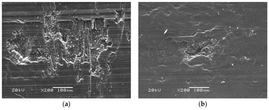
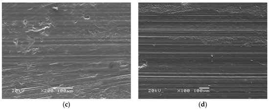
Figure 11.
SEM images of C/C composite under different material densities and orientations. (a) 1.80 g·cm−3, 1# orientation; (b) 1.80 g·cm−3, 2# orientation; (c) 1.85 g·cm−3, 1# orientation; (d) 1.85 g·cm−3, 2# orientation.
The tribological properties of the two density materials show different trends with the load, and this can be further analyzed and explained from the SEM images of the wear surface, as shown in Figure 12. For the sample with a density of 1.80 g/cm3, when the load is low, the brittle fracture occurs first because of the low strength and toughness of the carbon matrix. Fine granular wear debris is formed and compressed to form a transfer film with cracks (Figure 12a). With the increase in the load, the micro peaks on the friction surface are embedded into each other. Under the combined action of shear stress and compressive stress, the micro peaks break off and peel off (Figure 12b), and the wear debris is rapidly compressed and forms a transfer film on the friction surface. Cracks are formed at the positions where the material is weak or has defects. With the further expansion of the cracks, large transfer films are squeezed out from the friction surface and peeled off. Exposed fibers break under the reciprocating sliding shear action. At the same time, the stress concentration at the fiber end and the debonding between the fiber and the matrix occur, resulting in obvious warping. The broken fiber debris enters the friction surface, which increases the friction resistance and friction coefficient. The fiber debris is gradually crushed, compressed, and coated on the exposed and damaged surface, again forming a sub-friction layer. This self-repairing function plays a lubricating role and reduces the friction coefficient of the material. Under the influence of the above comprehensive factors, for a low-density sample, the friction coefficient fluctuates with the increase in the load, and the wear rate rises sharply. The material with a higher density (Figure 12c,d) has a relatively flat wear surface and higher connection strength between the fiber and matrix, so the friction coefficient and wear rate are low. With the increase in the load, the contact area of rough asperities increases, and the wear debris generated by the plowing action form a transfer film. Under this condition, adhesion has a greater influence on the friction properties of material compared with the deformation and fracture effects of asperities, and the wear rate increases slowly (see Figure 12d). Under the action of the friction shear stress, the transfer film is squeezed out of the friction surface again as lamellar or scaly wear debris, and the wear of the material under different loads has little difference.
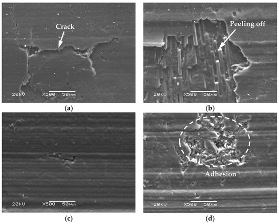
Figure 12.
SEM images of C/C composite under different loads. (a) 1.80 g·cm−3, 30 N, 96 mm·s−1; (b) 1.80 g·cm−3, 50 N, 96 mm·s−1; (c) 1.85 g·cm−3, 30 N, 96 mm·s−1; (d) 1.85 g·cm−3, 50 N, 96 mm·s−1.
The temperature of the friction surface increases with the increase in the sliding velocity, which leads to the decrease in the micro convex peak’s shear strength and the alleviation of wear. At the same time, it is easier to form a complete and continuous transfer film under high-temperature conditions, thus reducing the friction coefficient. It is noted that the material with a higher density is more likely and rapidly to form transfer films with an increasing sliding velocity. The transfer film layers move with the reciprocating sliding and friction action without a large amount of transfer films peeling off. As a result, the wear rate has little change. By comparing Figure 12a,c and Figure 13a,b, it can be seen that the materials with a low-density form transfer the film slowly at low sliding velocities (Figure 13a). The thin transfer film covers and wraps the fiber, and there are small cracks and more furrows on the surface under the plowing action of the abrasive particles. At this time, because the friction surface temperature is low, the shear strength of the micro convex peak is high, and the incomplete and discontinuous transfer film generated by the extrusion of the wear debris makes the friction coefficient larger and aggravates the material wear. When the sliding velocity is low (Figure 13b), although the material with high-density forms transfers the film slowly and the thin film is partially peeled off, the tight arrangement and less fracture of the fiber bundles alleviate the friction and wear. This makes the wear less than that of the material with a low density. For the material with high density, under high sliding velocity (Figure 12c), the surface of the material is flat, and the wear degree is relatively small.
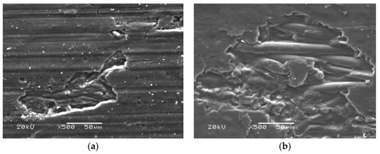
Figure 13.
SEM images of C/C composite under 30 N, 48 mm·s−1. (a) 1.80 g·cm−3, 30 N, 48 mm·s−1; (b) 1.85 g·cm−3, 30 N, 48 mm·s−1.
5. Conclusions
According to the application background of the finger seal, the friction and wear test of the C/C composite was carried out on a reciprocating tribo-tester. The effects of material density, fabric orientation, load, and sliding velocity on the friction coefficient and wear rate of C/C composites were studied. The friction and wear mechanism was analyzed by scanning electron microscope (SEM). The main conclusions are as follows.
- The friction coefficient and wear rate of materials with a perpendicular orientation are lower than those of materials with a parallel orientation, and the fluctuation amplitude is smaller when the material density is higher. Compared with low-density materials, high-density materials have a lower wear rate. The material surface with a parallel orientation has an abrasive wear and furrow effect, which is more significant when the material density is lower, and the friction surface is more seriously damaged. The material with a perpendicular orientation has a high fiber content in the non-woven cloth layer perpendicular to the friction plane and has a large bearing capacity, which alleviates wear.
- The change in the load has different effects on the friction and wear properties of materials with different densities. The friction coefficient of the low-density material increases with the increase in the load and fluctuates greatly, while that of the high-density material decreases with the load. The wear rate of the material shows a nonlinear increasing trend with the load, and the change is more significant under low-density conditions. With the increase in the load, the self-lubricating and self-healing characteristics of C/C composite are more obvious, especially when the material density is high. The adhesive wear behavior greatly alleviates the consumption of friction surfaces.
- The friction coefficient and wear rate of the low-density material decrease with the increase in the sliding velocity. The friction coefficient of high-density materials also decreases, but the wear rate decreases at first and then tends to be stable. Compared with the effect of the load, the effect of the sliding velocity on the wear properties of the C/C composite is much smaller. At a low sliding velocity, the friction surface is mainly abrasive wear, and the furrow effect is significant. With the increase in the velocity, it is easier to form a complete self-lubricating transfer film on the friction surface due to the temperature rise, which alleviates the wear.
Author Contributions
F.L.: writing—original draft preparation, methodology; L.L.; conceptualization, visualization; J.L.: formal analysis, supervision; X.P.; resources, investigation; C.S.; review and editing. All authors have read and agreed to the published version of the manuscript.
Funding
This work was supported by the National Natural Science Foundation of China under grants 52105183 and 52005160.
Data Availability Statement
Not applicable.
Conflicts of Interest
The authors declare no conflict of interest. The funders had no role in the design of the study; in the collection, analyses, or interpretation of data; in the writing of the manuscript; or in the decision to publish the results.
References
- Delgado, I.R.; Proctor, M.P. Continued investigation of leakage and power loss test results for competing turbine engine seals. In Proceedings of the 42th AIAA/ASME/SAE/ASEE Joint Propulsion Conference & Exhibit, Sacramento, CA, USA, 9–12 July 2006. [Google Scholar]
- Prcotor, M.P.; Kumar, A.; Delgdo, I.R. High-speed, high-temperature finger seal test result. J. Propuls. Power 2004, 20, 312–318. [Google Scholar] [CrossRef]
- Wang, A.L.; Muser, M.H. Percolation and Reynolds flow in elastic contacts of isotropic and anisotropic, randomly rough surfaces. Tribol. Lett. 2021, 69, 1. [Google Scholar] [CrossRef]
- Vlădescu, S.C.; Putignano, C.; Marx, N.; Keppens, T.; Reddyhoff, T.; Dini, D. The percolation of liquid through a compliant seal—An experimental and theoretical study. J. Fluids Eng. 2019, 141, 031101. [Google Scholar] [CrossRef]
- Pérez-Ràfols, F.; Larsson, R.; Almqvist, A. Modelling of leakage on metal-to-metal seals. Tribol. Int. 2016, 94, 421–427. [Google Scholar] [CrossRef]
- Zong, Z.K.; Su, H. Geometric feature and structure optimization of arc finger seal. Acta Aeronaut. Astronaut. Sin. 2010, 31, 393–399. [Google Scholar]
- Zhang, Y.C.; Chen, G.D. Applying nash equilibrium theory to achieving better design of finger seal. J. Northwestern Polytech. Univ. 2008, 26, 35–40. [Google Scholar]
- Vasilev, A.P.; Struchkova, T.S.; Nikiforov, L.A.; Okhlopkova, A.A.; Grakovich, P.N.; Shim, E.L.; Cho, J.H. Mechanical and Tribological Properties of Polytetrafluoroethylene Composites with Carbon Fiber and Layered Silicate Fillers. Molecules 2019, 24, 224. [Google Scholar] [CrossRef]
- Kaya, I.; Parlar, Z. The investigation of tribological behavior of carbon fiber-reinforced composite materials. Ind. Lubr. Tribol. 2018, 72, 211–216. [Google Scholar] [CrossRef]
- Cheng, H.; Xue, N.J.; Hou, W.Q. The application and development of carbon/carbon composites in aircraft and high-speed train braking systems. Carbon 2020, 184, 30–33. [Google Scholar]
- Li, G.; Yan, Q. Comparison of Friction and Wear Behavior Between C/C, C/C-SiC and Metallic Composite Materials. Tribol. Lett. 2015, 60, 15. [Google Scholar] [CrossRef]
- Shpenev, A.G.; Muravyeva, T.I.; Shkalei, I.V. Surface Change of Carbon–Carbon Composite Materials under Friction. J. Frict. Wear 2021, 42, 327–334. [Google Scholar] [CrossRef]
- Wang, L.Y.; Luo, R.Y.; Shang, H.D. Mechanical and friction-wear properties of two C/C composites using pre-oxidized polyacrylonitrile fibers and carbon fibers as the reinforcements. New Carbon Mater. 2020, 35, 26–33. [Google Scholar] [CrossRef]
- Li, Q.; Li, R.; Zhao, D.M. Effect of various technological parameters on friction and wear properties of aircraft carbon brake discs. Carbon 2022, 191, 23–27. [Google Scholar]
- Huang, L.H.; Li, H.J.; Liu, H.; Huang, F.P. Analysis of sealing characteristics of carbon/carbon composites. J. Mater. Sci. Eng. 2006, 24, 826–829. [Google Scholar]
- Zhao, J.G.; Li, K.Z.; Li, H.J. Effects of heat treatment temperature on the friction performance of C/C composites. Mater. Sci. Technol. 2007, 15, 606–609. [Google Scholar]
- Xiong, X.; Huang, B.Y.; Li, J.H.; Xu, H.J. Friction behaviours of carbon/carbon composites with different pyrolytic carbon textures. Carbon 2006, 44, 463–467. [Google Scholar] [CrossRef]
- Hutton, T.J.; David, J.; Brian, M. Effect of fibre orientation on the tribology of a model carbon carbon composite. Wear 2001, 249, 647–655. [Google Scholar] [CrossRef]
- Abdo, J.; Shamseldin, E.A. Comparative study of friction and wear of two generation of CVI C-C composite. Emir. J. Eng. Res. 2007, 12, 57–67. [Google Scholar]
- Kasem, H.; Bonnamy, S.; Berthier, Y.; Jacquemard, P. Fiber-matrix unbonding and plastic deformation in C/C composites under tribological loading. Wear 2010, 269, 104–111. [Google Scholar] [CrossRef]
- Fu, H.S.; Yang, M.; Ren, M.S. Tribology properties of C/C composites under different conditions. J. Shanghai Univ. 2018, 24, 947–954. [Google Scholar]
- Zhang, Y.C.; Zhou, R.M.; Yin, M.-H.; Zhang, Y.-T.; Hu, H.-T.; Cui, Y.-H. Experimental Investigation on Friction and Wear Performance of C/C Composite Finger Seal. J. Tribol. 2022, 144, 021701. [Google Scholar]
- Su, H.; Zhang, C.; Sun, S. Research on the wear model of carbon/carbon composite finger seal. Wear 2021, 476, 203682. [Google Scholar] [CrossRef]
- Lu, F.; Liu, J.; Pang, X.; Song, C.; Xu, Z. Wear modelling and sealing performance prediction of C/C composite finger seal. Proc. Inst. Mech. Eng. Part J J. Eng. Tribol. 2022. [Google Scholar] [CrossRef]
- Lu, F.; Liu, J.; Lu, H.Y. Experimental study on leakage and wear characteristics of C/C composite finger seal. Ind. Lubr. Tribol. 2020, 72, 1133–1138. [Google Scholar] [CrossRef]
- Lu, F.; Liu, J. Experimental and numerical investigation on wear behavior of carbon-fiber-reinforced carbon matrix composite used in rotary gas seals. Proc. Inst. Mech. Eng. Part J J. Eng. Tribol. 2021, 235, 575–587. [Google Scholar] [CrossRef]
- Lu, F.; Chen, G.D.; Su, H. Analysis of dynamic performance for 2.5D carbon-carbon composite finger seals. Acta Aeronaut. Astronaut. Sin. 2013, 34, 2616–2625. [Google Scholar]


Disclaimer/Publisher’s Note: The statements, opinions and data contained in all publications are solely those of the individual author(s) and contributor(s) and not of MDPI and/or the editor(s). MDPI and/or the editor(s) disclaim responsibility for any injury to people or property resulting from any ideas, methods, instructions or products referred to in the content. |
© 2023 by the authors. Licensee MDPI, Basel, Switzerland. This article is an open access article distributed under the terms and conditions of the Creative Commons Attribution (CC BY) license (https://creativecommons.org/licenses/by/4.0/).