Article

Adaptive Backlash Compensation for CNC Machining Applications

1
School of Mechanical and Electronics Engineering, Suzhou University, Suzhou 234000, China
2
School of Engineering, RMIT University, Melbourne VIC 3001, Australia
*
Author to whom correspondence should be addressed.
Machines 2023, 11(2), 193; https://doi.org/10.3390/machines11020193
Submission received: 10 January 2023 / Revised: 26 January 2023 / Accepted: 28 January 2023 / Published: 1 February 2023
(This article belongs to the Special Issue Recent Trends in Robot Motion Planning and Control)

Abstract

:
The mechanical transmission employed inside the computer numerical control (CNC) machine electromechanical system usually has an inherent backlash. As a position-controlled system is commonly used for the electromechanical system, the backlash limits the performance of the motion control system due to its nonlinearity and discontinuity. This paper proposes an effective method to adaptively detect and compensate for the backlash effect in real time, in which the end-effect load position of the CNC machine is estimated and controlled by the position-controlled servo system, in order to eliminate the influence of backlash on the contour path performance. The simulation results obtained from the model of a realistic CNC machine show the successful elimination of the error between the reference and the end-effector position and a significant improvement in the control system performance.

1. Introduction

CNC machines play an important role in manufacturing industries across different application areas, such as grinding, milling, lathes, and profile cuttings machines. The CNC software and the motion control systems have similar architectures for different applications, but their motion control performance requirements may vary from application to application [1].
The study of the motion control systems in CNC machines has two main aspects: trajectory generation and the feedback control system [2]. The former aspect aims to generate the position command of each contouring axis at every sampling instance, with the optimization of the cycle time as well as the consideration of the vibration suppression [3,4,5,6]. On the other hand, to increase the CNC machine productivity while maintaining the required control performance, the feedback control system must deal with the mechanical load dynamics inside the machine design. Because the mechanical dynamics can be nonlinear and discontinuous due to the transmission characteristics, the problem of backlash naturally occurs in CNC machine control [7,8].
Backlash, also called the dead zone, is induced in the mechanical transmissions, such as the gearbox, ball screw, and rack and pinion, which are generally required in the axis design of CNC machines. The existence of backlash limits the motion control performance in CNC machining accuracy. Many backlash compensation methods have been introduced. Kao demonstrated an early study and compensation approach to backlash in CNC lathes application [9], which proposed a simple strategy to compensate for the backlash distance in the reverse direction, while the backlash distance was first experimentally approximated. Tarng extended a similar approach to different CNC machine applications [10]. Jukić illustrated three different backlash compensation methods for the position feedback control system, with advantages and disadvantages, such as additional torque sensors or noise sensitivity [11]. In [12], a two-step identification method was proposed to estimate the backlash distance, but the measurement of the load speed was required as one of the identification signals. However, additional sensors are not usually available in many CNC machine applications during normal operation. Moosavian introduced a backlash detection method based on the frequency response result from the vibration experiment [13].
Backlash compensation is also essential in other applications of motion control. Chen compensated for backlash by employing the backlash parameter estimation together with an adaptive control design for the active vibration isolation system [14]. There are several observer-based backlash compensation approaches as well; for example, a disturbance observer design was introduced for a humanoid robot joint [15,16]. Yang demonstrated the suppression of the mechanical vibration caused by resonance and backlash in a two-mass system using the torque disturbance observer [17]. Recently, Zou proposed the transmission backlash compensation for a surgery robot, based on the tension and displacement model of a cable–pulley system [18]. Xu demonstrated a new control method to eliminate the backlash error of the pneumatic control valve by employing a self-calibration PID control method as well as the physical model of the system process [19]. In [20], Li presented a lifting motion control method of hydraulic manipulators considering the system nonlinearities, uncertainties, and the valve backlash compensation.
The mechanical backlash discussed in this paper refers to the innate gap inside the transmission of the electromechanical system, which causes the discontinuity between the electrical motor and its load. To achieve high precision in CNC machines, there are other factors that will influence the final contour control performance even though the servo position control performance is ideal. A compensation method was proposed to eliminate the machine error caused by the thermal distortion in the machine tools with large scale [21]. Another type of machine error that propagated during the assembly of multiaxis was discussed in [22], as well as the development of an assessment method for geometrical accuracy. The deflection and deformation of the mechanical structure during the contact machining process would also cause uncontrolled position error in the contour path; hence, the study of system stiffness and the deflection induced by the cutting force was investigated in [23], and another study in [24] described an approach to monitor the tool wear condition by using acoustic emission and vibration signals for high-value parts and tools. Therefore, it is important to distinguish these machine uncertainties from the mechanical backlash discussed in this paper; this work focuses on compensating the backlash gap inside the transmission while assuming that the mechanical damping and stiffness values are consistent or changing more slowly than the estimation process, and the deflection and deformation are not included in this study.
This paper aims to compensate the backlash inside the mechanical transmission of the CNC machine, by utilizing the common measurement inside the servo drive system, as well as the benefit of a smooth trajectory command signal generated from the CNC. The proposed method identifies and detects the backlash in real time; thus, the prior information of the backlash distance is not required. The paper is organized as follows: Section 2 introduces an overall description of the motion control system in CNC machines, followed by illustrating the single axis servo control system, the load mechanical model with backlash dynamics, and its impact. In Section 3, the proposed backlash compensation method is introduced and discussed, where the estimation of the system parameters is proposed. Based on the real-time estimation algorithm, the adaptive compensation method follows. Finally, Section 4 demonstrates the efficacy of the proposed approach through simulation studies, and the results are compared with an existing method. The paper is concluded in Section 5.

2. System Description

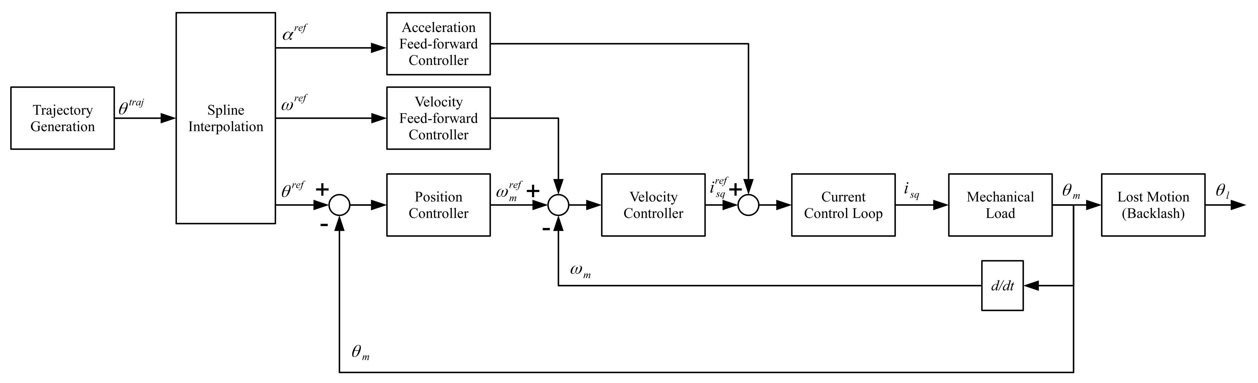
2.1. Overall Description
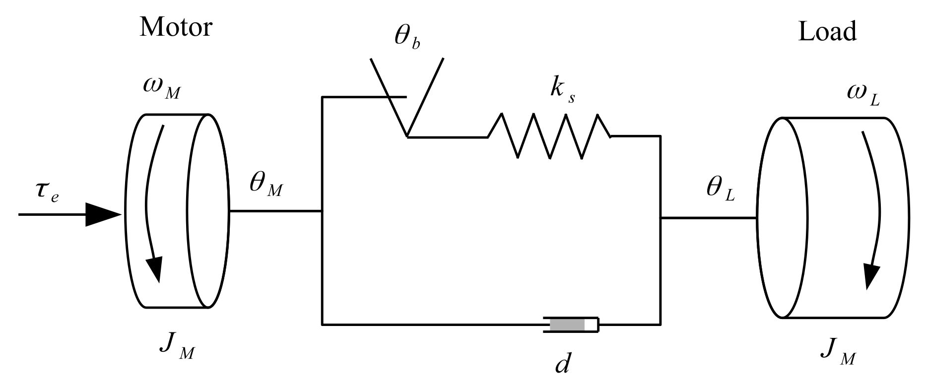
In CNC machines, the users design the manufacturing shapes and profiles in the CAD (Computer-Aided Design) and CAM (Computer-Aided Manufacturing) software systems, which generate the corresponding machine codes in the part-program language. The CNC operates the machine components by using the machine codes to fulfill the application requirements [1]. In terms of motion control, the manufacturing shapes are converted to a combination of line and arc motions in the path space; then, the CNC converts these lines and arcs to trajectory commands with a time stamp to each contouring axis via inverse kinematics. As a result, the CNC computer guarantees that the position commands of each axis are sent to its servo drive via a real-time communication protocol, and the servo drive achieves the feedback position control for its best performance.
A simplified block diagram of the existing servo control system in the CNC machining application is shown in Figure 1. In this figure, for simplicity, the motor electrical dynamics and its control loops are lumped into the Current Control Loop block, which has been tuned to have a sufficiently high bandwidth with critical damping in order to minimize its impact on the outer servo control loops. The current control systems typically use the classic Field-Oriented Control (FOC) method, where the flux-generated current i s d is controlled to 0, and the i s q current is controlled to generate the motor electromagnetic torque.
Since the motion path and trajectory are generated by the CNC, the position reference signal is received at the joint servo drive at each communication sample, and the communication sampling time is generally found to be slower than the servo drive control loops. Thus, an interpolation method is required to fit the position reference between the communication updates in order to avoid the discontinuity of the position reference to the servo control loops.
By employing the spline interpolation method, the reference value of the position, velocity, and acceleration signals are estimated at each servo loop sampling interval. While the position reference signal θ r e f is used as the position control loop command, the velocity ω r e f and acceleration α r e f reference signals are utilized for the feed-forward controllers.
Because the system architecture decouples the computer level trajectory planning and the servo drive level feedback position control, the productivity of the CNC machines is generally limited by the servo drive control performance of the contouring axes, where the servo drive control performance is again limited by the load mechanical conditions.
Among the mechanical dynamics, backlash plays a significant role in the servo drive position control performance. The rest of the section will illustrate the effect of backlash on servo control performance.

2.2. System Model

The mechanical load and motor shaft are firstly assumed to be one rigid body. Under this assumption, the dynamic model of the motion is described as:
τ e ( t ) = J T θ ¨ M ( t ) + b v θ ˙ M ( t ) + τ d ( t ) ,
where τ e ( t ) is the electromagnetic torque generated by the servo motor, θ M ( t ) represents the motor shaft position, τ d ( t ) includes the load torque, and the disturbance torque of the system, such as the Coulomb friction, gravity force, and so on. The model parameter J T = J M + J L is the total inertia moved by the motor shaft, and b v is equivalent to the viscous friction of the motion. Since τ d ( t ) in (1) is generally constant or piece-wise constant during normal operations, it can be rejected by the integral controller in the feedback control system.
In CNC machines, the dominant mechanical compliance loaded on the motor shaft can be described by the two mass-spring damping model, which has the following transfer function model:
θ M ( s ) I s q ( s ) = K t J T s 2 + b v s J L s 2 + d s + k s J M J L J T s 2 + d s + k s .
Figure 2 illustrates the backlash in the mechanical transmission within the two mass-spring damping models, where the abrasives are described in Table 1.
Due to the discontinuity of the backlash, the actual inertia moved by the motor shaft is discontinuous, and the dynamic model in (2) becomes
θ M ( s ) I s q ( s ) = K t J T s 2 + b v s J L s 2 + d s + k s J M J L J T s 2 + d s + k s , | θ b |   b K t J M s 2 + b v s , | θ b |   < b ,
where the backlash angle θ b = θ M θ L and initially starts from the middle of the total backlash angle.
The simulation result in Figure 3 illustrates the servo position control outcomes at the motor shaft as well as the end-effector positions. The simulation model had a backlash distance of 0.1 rad; the existing cascaded control system in the servo drive, as shown in Figure 2, can achieve precise and stable position control outcome based on the motor position feedback but not the position at the end-effector. It deteriorates the final machine outcome on the workpiece, especially for high-precision applications, such as grinding machines.

3. Proposed Compensation Method

This section proposes a backlash compensation method, which eliminates the effect of the backlash at the end-effector position, without introducing any additional hardware changes to the system. The proposed method aims to adaptively compensate for the impact of the backlash dynamics on the final position control result.
The concept of the proposed approach is illustrated in Figure 4, which contains two blocks where the actual load inertia carried by the motor shaft is firstly estimated in real time, and the compensation scheme is tailored with tunable threshold condition so that the real-time backlash distance is estimated. As a result, the end-effector position is estimated and utilized for position feedback control.

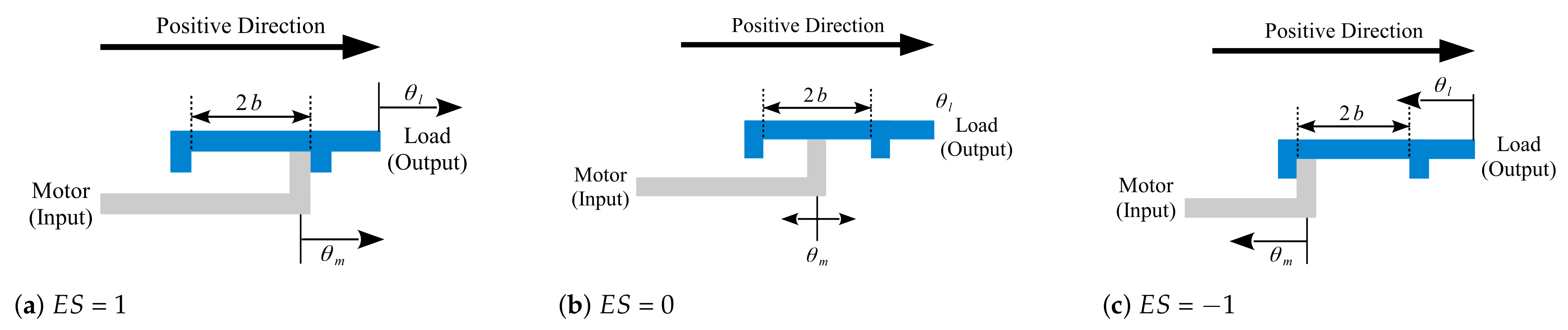
3.1. Mechanical Engagement Status

Prior to compensating for the backlash, the term E S is introduced to describe the backlash based on the mechanical engagement status. The engagement status E S ( k ) at sampling instance k is defined as:
E S ( k ) = 1 , θ b b 0 , | θ b |   < b 1 , θ b b ,
where the initial condition is assumed as E S ( 0 ) = 0 .
As shown in Figure 5, the mechanical engagement status E S is defined as 1 when the motor input is engaged to the load in the positive direction and as E S = 1 when the motor input is engaged in the negative direction; in both scenarios, the motor shaft carries the full load inertia. On the other hand, when the motor input is located or moving within the total backlash angle 2 b , the engagement status is defined as 0, and the motor shaft no longer carries the load inertia.

3.2. Recursive Least Square Regulation Estimation

The first step in the proposed backlash compensation method is to estimate the status of the mechanical engagement. From (3), the change in the E S ( k ) value obeys the condition of the load dynamics. Hence, E S ( k ) can be estimated by identifying the mechanical load inertia that is actually carried by the motor shaft.
The recursive least squares method is employed to estimate the moment of inertia that is carried by the motor shaft. The model transfer function (2) is discretized by using the first-order approximation of the derivatives of the continuous-time system to obtain:
θ M ( k ) + a 1 θ M ( k 1 ) + a 2 θ M ( k 2 ) = b 0 i s q ( k ) ,
where k denotes the sampling instant k, T s is the sampling interval, and the rest of the parameters are b 0 = k t T s 2 J T + b v T s , a 1 = 2 J T + b v T s J T + b v T s , and a 2 = J T J T + b v T s .
Upon obtaining the discrete time model, the parameter vector is chosen as θ = [ a 1 a 2 b 0 ] T , and the regression vector is ϕ ( k ) = [ θ M ( k 1 ) θ M ( k 2 ) i s q ( k ) ] T . The recursive least squares algorithm is used to estimate the parameter vector θ in real time. The algorithm consists of the following two steps.
  • At the sampling instant k, we calculate the estimated parameter vector θ ^ ( k )
    θ ^ ( k ) = θ ^ ( k 1 ) + P ( k 1 ) ϕ ( k ) θ M ( k ) ϕ ( k ) θ ^ ( k 1 ) .
  • We update the covariance matrix P ( k ) using
    P ( k ) = P ( k 1 ) P ( k 1 ) T ϕ ( k ) ϕ ( k ) T P ( k 1 ) 1 + ϕ ( k ) T P ( k 1 ) ϕ ( k ) .
    To accurately capture the abrupt parameter change, the recursive computation requires continuous excitation; hence, the matrix P ( k ) in the least square algorithm is reset to P ( 0 ) at the instance when the acceleration reference α r e f becomes a nonzero value. As a result, the computation of matrix P ( k ) becomes:
    P ( k ) = P 0 , if | α r e f ( k ) | > 0 a n d | α r e f ( k 1 ) | = 0 P ( k 1 ) P ( k 1 ) T ϕ ( k ) ϕ ( k ) T P ( k 1 ) 1 + ϕ ( k ) T P ( k 1 ) ϕ ( k ) , otherwise ,
    where P 0 is the initial condition of the P matrix.
The initialization of the adaptive backlash compensation is suggested with the following definitions:
J ^ T ( 0 ) = J M b ^ v ( 0 ) = 0 P ( 0 ) = P 0 E S ( 0 ) = 0 θ ^ b ( 0 ) = 0 θ ^ L ( 0 ) = θ M ( 0 ) ,
where J ^ T ( 0 ) and b ^ v ( 0 ) are used to compute the initial value of vector θ ( t k ) , whereas the motor torque constant k t , the motor inertia J M , and the sampling interval T s are assumed to be known.
As a result, at the sampling instant k, the real-time load inertia carried by the motor shaft is estimated as follows.
J ^ T ( k ) = max a ^ 2 ( k ) k t T s 2 b ^ 0 ( k ) , ( a ^ 1 ( k ) 1 ) k t T s 2 b ^ 0 ( k ) .

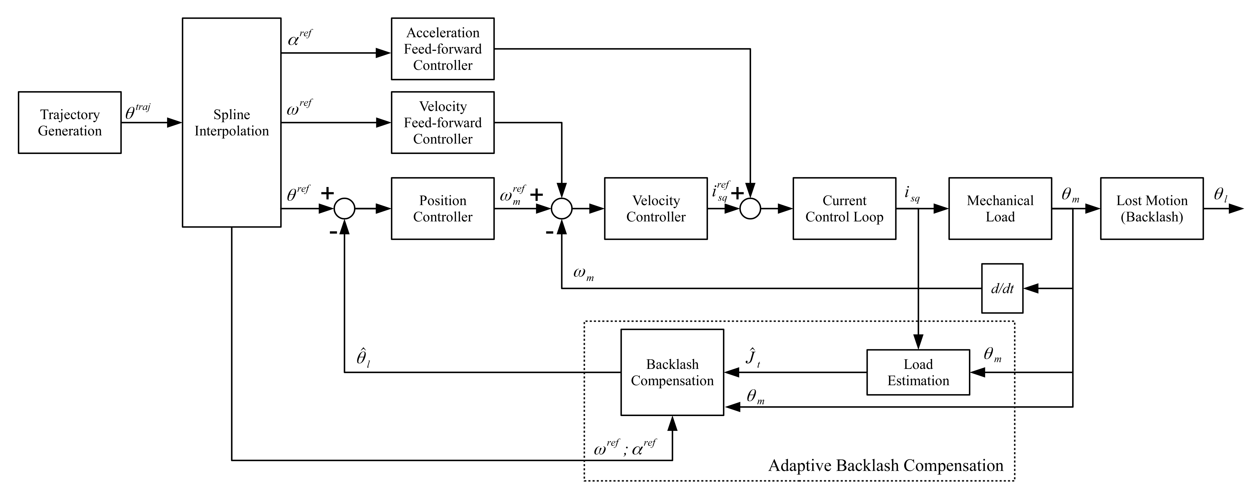
3.3. Adaptive Backlash Compensation

The backlash transition or E S ( k ) value change will occur whenever the direction of motion acceleration alters; the acceleration reference signal α r e f from the spline interpolation is employed as one condition of the E S ( k ) estimation. Given that the reference signal α r e f is normally noise free and ahead in time, its status is utilized to reset the parameter estimation in the previous subsection as well as to determine the value after the backlash transition occurs.
Thus, the estimation of the mechanical engagement status E S ^ ( k ) is computed using the following form:
E S ^ ( k ) = sign ( α r e f ) , if J ^ T ( k ) > J m i n a n d E S ^ ( k 1 ) = 0 0 , if | J ^ T ( k ) | J m i n a n d E S ^ ( k 1 ) = sign ( α r e f ) E S ^ ( k 1 ) , otherwise ,
where J m i n is the condition threshold of the estimated inertia parameter. Since the moment of inertia of the motor rotor J M is provided in the document from the motor manufacturer, J m i n can be defined as: J m i n = 1 1 λ J M , where 0 < λ < 1 . The estimation of backlash angle θ ^ b ( k ) is computed at each sample instance k, based on the estimation of the load inertia and the mechanical engagment status in (10) and (11).
θ ^ b ( k ) = θ ^ b ( k 1 ) + Δ θ M ( k ) Δ θ c , if | J ^ T ( k ) | J m i n a n d f E S ^ ( k 1 ) = 0 θ ^ b ( k 1 ) , otherwise ,
where Δ θ M ( k ) = θ M ( k ) θ M ( k 1 ) , and Δ θ c is the latched motor velocity Δ θ M ( k ) , which is captured at the instance when the E S ^ ( k ) = 0 condition is fulfilled.
As a result, the estimated backlash is subtracted from the measured motor position to estimate the load position θ ^ L at the end-effector,
θ ^ L ( k ) = θ M ( k ) θ ^ b ( k ) .
The estimated load position is then fed to the position control loop for the servo control to achieve the backlash compensation.

4. Simulation Results

4.1. Simulation Setup

The simulation model was implemented based on an example of an industrial CNC machine servo axis. To demonstrate the proposed compensation method, a rotary axis was simulated with a pre-generated motion profile. The rotary axis was composed of an industrial servo PMSM motor and a mechanical load with backlash. The motor and the mechanical load parameters are shown in Table 2; note that the load parameters are defined and reflected in the motor side.
The example motion profile of a point-to-point jerk-limited motion, as displayed in Figure 6, was generated as the command position signal θ r e f for the simulation. The motion profile was generated from the CNC at a sampling or communication rate of 1 ms; then, the received position command was interpolated to 250 μs before reaching the servo control loops. Thus, both the position and velocity loops were sampled at a 250 μs rate, and the inner current control loop was sampled at 50 μs to form the cascaded control structure.
Since the main contribution of this paper focuses on the backlash compensation method, the control system followed the common structure used in the industrial servo drive, with PID controllers. To fairly compare the control performance before and after compensation, the PID controllers of the current, velocity, and position control loops were tuned with identical parameter values, as designed in Table 3.

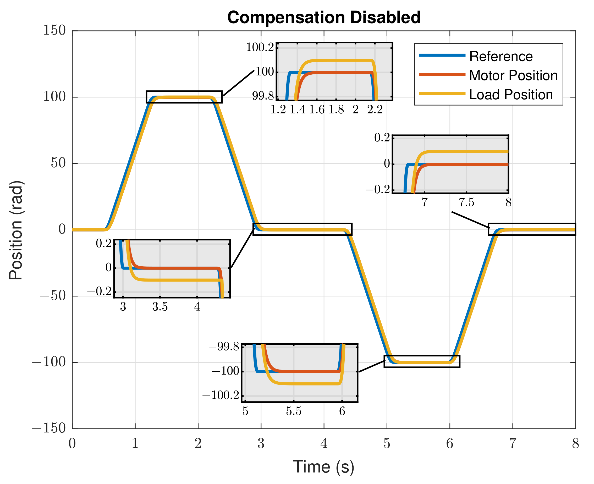
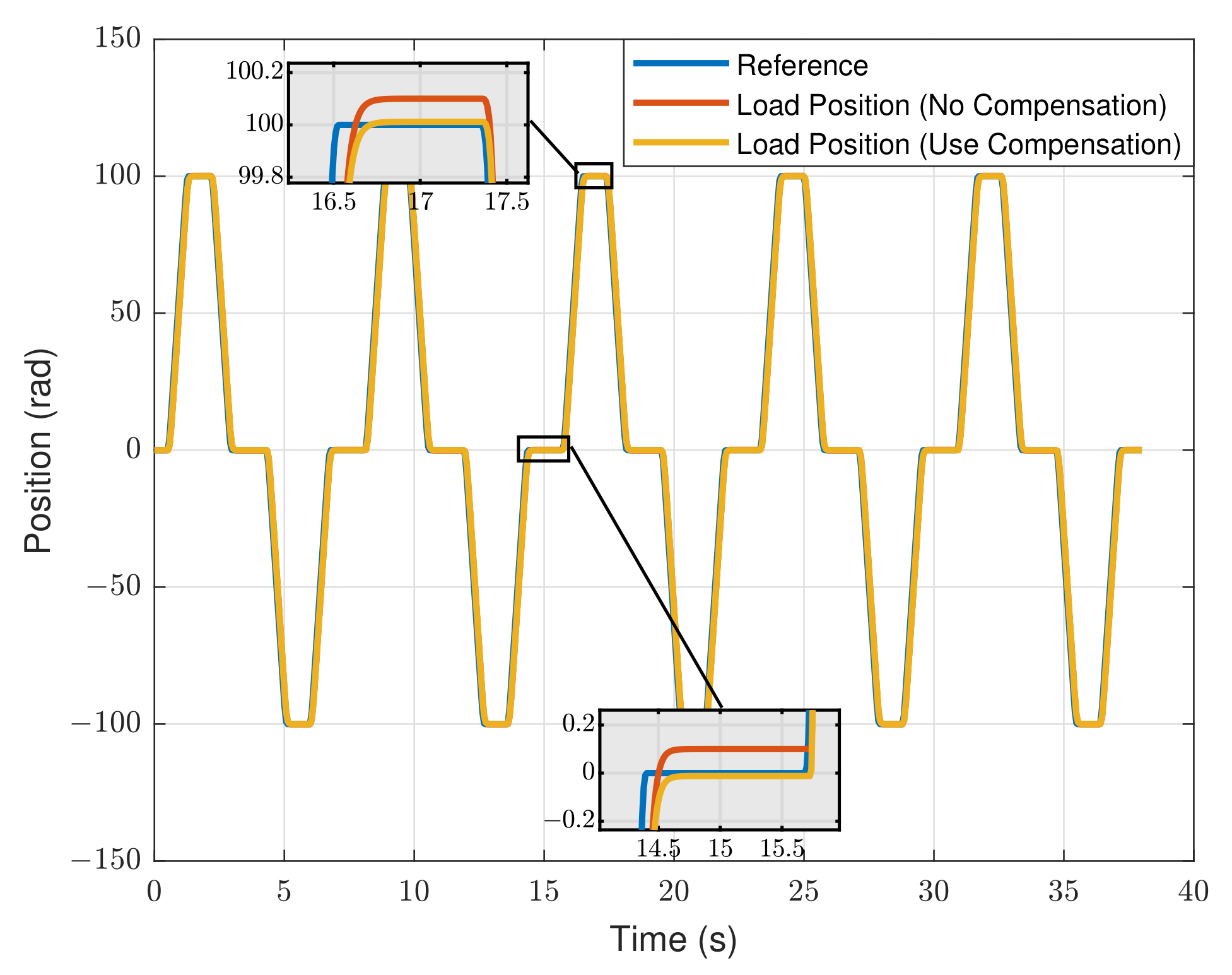
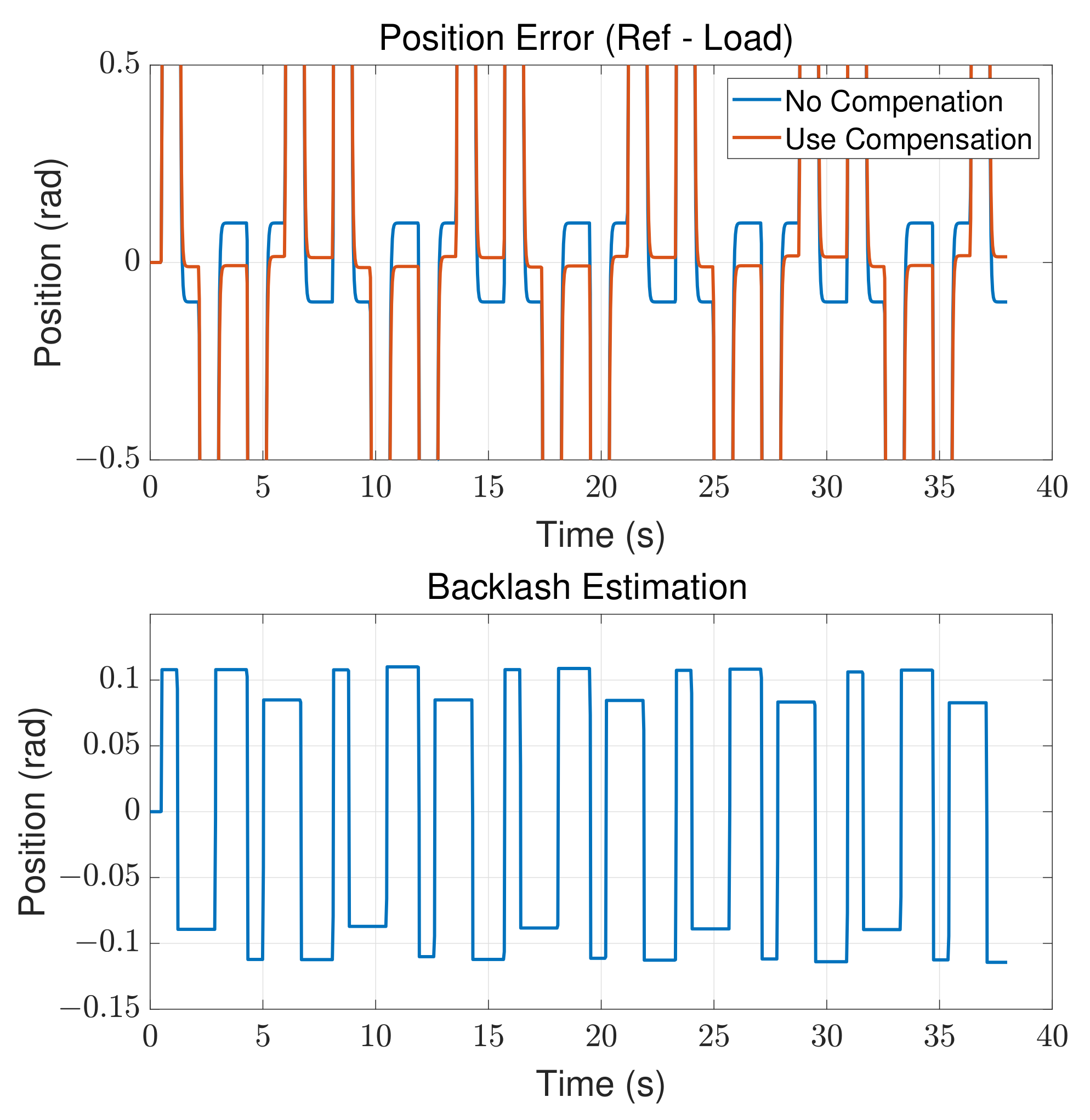
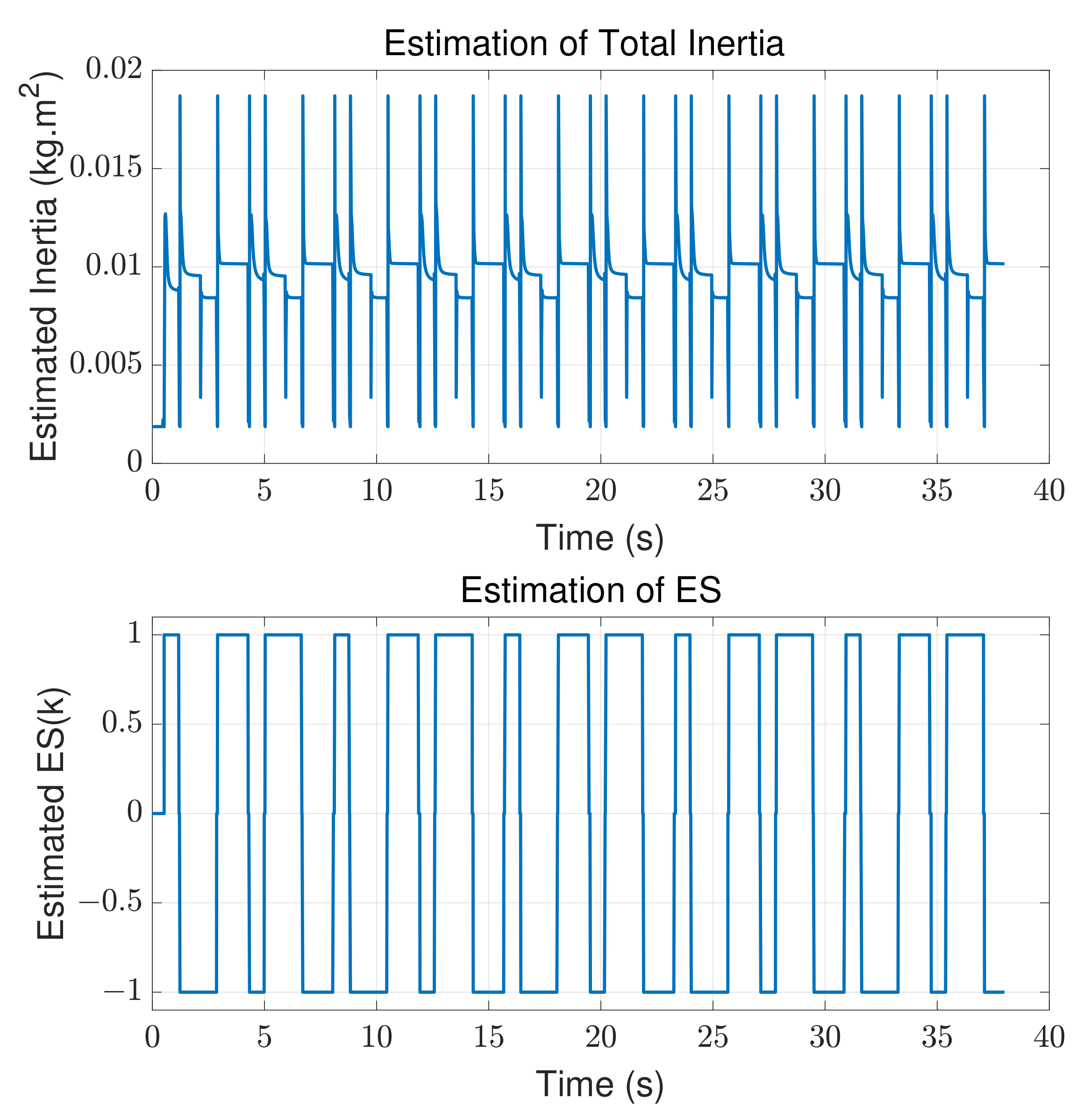
4.2. Result Analysis

The simulation results of the motion control without the backlash compensation are displayed in Figure 7, whereas the results with backlash compensation enabled are shown in Figure 8. In both figures, the position control results are shown in the upper subplot, the velocity control results are in the middle subplot, and the DQ current measurement is in the bottom subplot, to demonstrate the full motion control states during the simulation.
Figure 9 illustrates the zoom-in view for the comparison of the position control results at the load side, between the backlash compensation method disabled and enabled cases. The backlash compensation method successfully eliminated the backlash effect at the load position and reduced the influence of the transmission backlash on the end-effector during the CNC machining processing.
Figure 10 plots the zoom-in view of the position error between the reference and load position signal at the top; since the proportional controller is normally used in the position control loop, the position tracking error is nonzero whenever the velocity is nonzero. Given that the total backlash distance was defined as 0.2 rad, as shown in Table 2, the lower plot displays the online estimation of the backlash distance, which had an amplitude within ±0.1 rad with an error less than 15%. Hence, the contour position error when applying the compensation method, as shown in the upper graph, was less than 15% of the error before applying the compensation. As a result, the compensation method adaptively rejected the estimated backlash distance at the final position control result. To demonstrate the estimation result during the compensation, Figure 11 shows the simulation results of the estimation of the total inertia value and the estimation of the mechanical engagement status E S ^ ( k ) . The estimated total inertia carried by the motor shaft converged rapidly to its stable value; then, together with the conditions and thresholds which were proposed in (11), the mechanical engagement status was estimated and plotted.

5. Conclusions

This paper proposed a backlash compensation method that adaptively and continuously estimated and compensated the backlash effect at the position feedback signal; the feedback control system achieved the contour path goal at the end-effect position. Hence, the contour error at the end-effector became less than 15 percent of the error without applying the compensation method. The proposed method is reliable and stable, as the compensation scheme employs the conditions from the command signal stream. The simulation results showed that the method could be quickly implemented and adopted by the existing servo control system in the CNC machines. Moreover, such a method has a strong potential to be extended to other motion control applications that suffer from backlash issues. The potential future works are listed as follows:
  • The proposed method will be validated with experimental devices. The experiment can start with a test bench of back-to-back motors, which has a coupler connecting the motor shafts with known stiffness and configurable backlash. Then, the experiment can be conducted on a single axis on a CNC machine, where the axis employs a mechanical transmission with a noticeable backlash that influences the contour performance. Finally, the experiment can be extended to the multiaxis contour control performance verification.
  • Another extension of this work is to adaptively detect the stiffness and damping factor in the estimation, which will bring more variables into the picture; hence, it would be able to achieve more robust and accurate performance for these applications that require high precision. On the other hand, the real-time estimation of mechanical dynamics can also contribute to the study of deflection and deformation issues.
  • Accumulating the knowledge from the works in the previous two points, the outcomes would potentially promote the proposed approach to applications other than CNC machines, such as robot joints.

Author Contributions

Conceptualization, L.G.; Methodology, L.G.; Software, L.G.; Validation, L.W.; Investigation, L.G.; Writing—original draft, L.G.; Writing—review and editing, L.W.; Project administration, F.H. All authors have read and agreed to the published version of the manuscript.

Funding

The Doctoral Research Initiation Project of Suzhou University under Grant 2020BS005.

Data Availability Statement

Not applicable.

Conflicts of Interest

The authors declare no conflict of interest.

References

  1. Yeung, C.H.; Altintas, Y.; Erkorkmaz, K. Virtual CNC system. Part I. System architecture. Int. J. Mach. Tools Manuf. 2006, 46, 1107–1123. [Google Scholar] [CrossRef]
  2. Altintas, Y. Manufacturing Automation: Metal CuttingMechanics, Machine Tool Vibrations, and CNC Design; Cambridge University Press: Cambridge, UK, 2000. [Google Scholar]
  3. Heng, M. Smooth and Time-Optimal Trajectory Generation for High Speed Machine Tools. Master’s Thesis, University of Waterloo, Waterloo, ON, Canada, 2008. [Google Scholar]
  4. Erkorkmaz, K.; Yeung, C.H.; Altintas, Y. Virtual CNC system. Part II. High speed contouring application. Int. J. Mach. Tools Manuf. 2006, 46, 1124–1138. [Google Scholar] [CrossRef]
  5. Sencer, B. Smooth Trajectory Generation and Precision Control of 5-Axis CNC Machine Tools. Ph.D. Thesis, University of British Columbia, Vancouver, BC, Canada, 2009. [Google Scholar]
  6. Erkorkmaz, K.; Altintas, Y. High speed CNC system design. Part I: Jerk limited trajectory generation and quintic spline interpolation. Int. J. Mach. Tools Manuf. 2001, 41, 1323–1345. [Google Scholar] [CrossRef]
  7. Ackermann, J.; Müller, P. Dynamical Behaviour of Nonlinear Multibody Systems Due to Coulomb Friction and Backlash. In Proceedings of the IFAC/IFIP/IMACS Symposium on Theory of Robots, Vienna, Austria, 3–5 December 1986; Volume 19, pp. 193–198. [Google Scholar] [CrossRef]
  8. Erkorkmaz, K.; Altintas, Y. High speed CNC system design. Part III: High speed tracking and contouring control of feed drives. Int. J. Mach. Tools Manuf. 2001, 41, 1637–1658. [Google Scholar] [CrossRef]
  9. Kao, J.; Yeh, Z.; Tarng, Y.; Lin, Y. A study of backlash on the motion accuracy of CNC lathes. Int. J. Mach. Tools Manuf. 1996, 36, 539–550. [Google Scholar] [CrossRef]
  10. Tarng, Y.S.; Kao, J.Y.; Lin, Y.S. Identification of and compensation for backlash on the contouring accuracy of CNC machining centres. Int. J. Adv. Manuf. Technol. 1997, 13, 77–85. [Google Scholar] [CrossRef]
  11. Jukić, T.; Perić, N. A comparative study of backlash compensation methods. In Proceedings of the 2003 European Control Conference (ECC), Cambridge, UK, 1–4 September 2003; pp. 3261–3266. [Google Scholar] [CrossRef]
  12. Ravanbod-Shirazi, L.; Besançon-Voda, A. Backlash Identification: A Two Step Approach. In Proceedings of the 15th IFAC World Congress, Barcelona, Spain, 21–26 July 2002; Volume 35, pp. 85–90. [Google Scholar] [CrossRef]
  13. Moosavian, S.A.A.; MohammadiAsl, E. Backlash Detection in CNC Machines Based on Experimental Vibration Analysis. In Proceedings of the 2008 IEEE Conference on Robotics, Automation and Mechatronics, Chengdu, China, 21–24 September 2008; pp. 393–398. [Google Scholar] [CrossRef]
  14. Chen, C.; Liu, Z.; Zhang, Y.; Chen, C.L.P.; Xie, S. Actuator Backlash Compensation and Accurate Parameter Estimation for Active Vibration Isolation System. IEEE Trans. Ind. Electron. 2016, 63, 1643–1654. [Google Scholar] [CrossRef]
  15. Kang, M.J.; Park, J.H.; Kim, J.H.; Huh, U.Y. A disturbance observer design for backlash compensation. Int. J. Control. Autom. Syst. 2011, 9, 742. [Google Scholar] [CrossRef]
  16. Jung, B.J.; Kong, J.S.; Lee, B.H.; Ahn, S.M.; Kim, J.G. Backlash compensation for a humanoid robot using disturbance observer. In Proceedings of the 30th Annual Conference of IEEE Industrial Electronics Society, 2004. IECON 2004, Busan, Republic of Korea, 2–6 November 2004; Volume 3, pp. 2142–2147. [Google Scholar] [CrossRef]
  17. Yang, M.; Zheng, W.; Yang, K.; Xu, D. Suppression of mechanical resonance using torque disturbance observer for two-inertia system with backlash. In Proceedings of the 2015 9th International Conference on Power Electronics and ECCE Asia (ICPE-ECCE Asia), Seoul, Republic of Korea, 1–5 June 2015; pp. 1860–1866. [Google Scholar] [CrossRef]
  18. Zou, S.; Li, G.; Huang, Y. Transmission Backlash Compensation and Grasping Force Estimation of Surgical Instruments for the Laparoscopic Minimally Invasive Surgery Robot. Appl. Sci. 2022, 12, 12126. [Google Scholar] [CrossRef]
  19. Xu, H.; Li, Y.; Zhang, L. A New Control Method for Backlash Error Elimination of Pneumatic Control Valve. Processes 2021, 9, 1378. [Google Scholar] [CrossRef]
  20. Li, L.; Lin, Z.; Jiang, Y.; Yu, C.; Yao, J. Valve Deadzone/Backlash Compensation for Lifting Motion Control of Hydraulic Manipulators. Machines 2021, 9, 57. [Google Scholar] [CrossRef]
  21. Gomez-Acedo, E.; Olarra, A.; Orive, J.; Lopez de la Calle, L.N. Methodology for the design of a thermal distortion compensation for large machine tools based in state-space representation with Kalman filter. Int. J. Mach. Tools Manuf. 2013, 75, 100–108. [Google Scholar] [CrossRef]
  22. Díaz-Tena, E.; Ugalde, U.; López de Lacalle, L.N.; de la Iglesia, A.; Calleja, A.; Campa, F.J. Propagation of assembly errors in multitasking machines by the homogenous matrix method. Int. J. Adv. Manuf. Technol. 2013, 68, 149–164. [Google Scholar] [CrossRef]
  23. Salgado, M.; López de Lacalle, L.; Lamikiz, A.; Muñoa, J.; Sánchez, J. Evaluation of the stiffness chain on the deflection of end-mills under cutting forces. Int. J. Mach. Tools Manuf. 2005, 45, 727–739. [Google Scholar] [CrossRef]
  24. Barreiro, J.; Fernández-Abia, A.; González-Laguna, A.; Pereira, O. TCM system in contour milling of very thick-very large steel plates based on vibration and AE signals. J. Mater. Process. Technol. 2017, 246, 144–157. [Google Scholar] [CrossRef]
Figure 1. Block diagram of a common servo control system in the CNC machine applications.
Machines 11 00193 g001
Figure 2. Illustration of the mechanical backlash model for two rotary masses.
Machines 11 00193 g002
Figure 3. Effectof the mechanical backlash on the servo control.
Machines 11 00193 g003
Figure 4. A block diagram of the proposed servo control system in the CNC machine applications.
Machines 11 00193 g004
Figure 5. Illustration of the engagment status E S .
Machines 11 00193 g005
Figure 6. Point-to-pointmotion profile.
Machines 11 00193 g006
Figure 7. Controlperformance without the backlash compensation.
Machines 11 00193 g007
Figure 8. Controlperformance with the backlash compensation.
Machines 11 00193 g008
Figure 9. Position control comparison with and without backlash compensation.
Machines 11 00193 g009
Figure 10. Upper: position error comparison. Lower: backlash distance estimation.
Machines 11 00193 g010
Figure 11. Upper: estimation of the total inertia carried by the motor shaft. Lower: estimation of the mechanical engagement status E S .
Machines 11 00193 g011
Table 1. Table of Abbreviations.
SymbolNameSI Unit
τ e Motor electromagetic torqueNm
ω M Motor angular velocityrad/s
ω L Load angular velocityrad/s
θ M Motor inertia anglerad
θ L Load inertia angularrad
θ b Real-time backlash anglerad
bHalf of total backlash anglerad
J M Motor inertia kg · m 2
J L Load inertia kg · m 2
k s Mechanical stiffnessNm/rad
dMechanical dampingNm/(rad/s)
Table 2. System Parameters.
a PMSM Motor Parameters
Motor ParametersValueUnit
Line to line resistance 0.42 Ω
Line to line inductance 0.0045 H
Number of poles10
Rotor inertia 0.00189 kg · m 2
Torque constant 1.08 Nm
Voltage constant296V/krpm
b Mechanical Load Parameters
Load ParametersValueUnit
Load inertia 0.0065 kg · m 2
Viscous friction coefficient 0.01 Nm · s / rad
Spring damping factor 0.8 Nm · s / rad
Spring stiffness coefficient2000Nm/rad
Gear ratio (In:Out)5:1
Total backlash distance 0.2 rad
Table 3. Plant Parameters.
Controller ParameterValue
Current proportional gain15
Current integral time 0.00185
Velocity proportional gain 1.74
Velocity integral time 0.0086
Position proportional gain25
Disclaimer/Publisher’s Note: The statements, opinions and data contained in all publications are solely those of the individual author(s) and contributor(s) and not of MDPI and/or the editor(s). MDPI and/or the editor(s) disclaim responsibility for any injury to people or property resulting from any ideas, methods, instructions or products referred to in the content.

