Article

Smartphone-Based Indoor Floor Plan Construction via Acoustic Ranging and Inertial Tracking †

School of Software Engineering, Beijing Jiaotong University, Beijing 100044, China
*
Author to whom correspondence should be addressed.
This paper is an extended version of our paper published in Chuize Meng, Shan Jiang, et al, “BatMapper-Plus: Smartphone-Based Multi-level Indoor Floor Plan Construction via Acoustic Ranging and Inertial Sensing”, 17th International Conference on Wireless Algorithms, Systems, and Applications (WASA 2022), Dalian, China, 24–26 November 2022.
Machines 2023, 11(2), 205; https://doi.org/10.3390/machines11020205
Submission received: 28 December 2022 / Revised: 26 January 2023 / Accepted: 30 January 2023 / Published: 1 February 2023
(This article belongs to the Section Robotics, Mechatronics and Intelligent Machines)

Abstract

:
The lack of indoor floor plans is one of the major obstacles to ubiquitous indoor location-based services. Dedicated mobile robots with high-precision sensors can measure and produce accurate indoor maps, but the deployment remains low for the public. Computer vision techniques are adopted by some existing smartphone-based methods to build the 3D point cloud, which have the cost of a quantity of the efforts of image collection and the risk of privacy issues. In this paper, we propose BatMapper-Plus which adopt acoustic ranging and inertial tracking to construct precise and complete indoor floor plans on smartphones. It emits acoustic signals to measure the distance from the smartphone to a neighbouring wall segment, and produces accessible areas by surrounding the building during walking. It also refines the constructed indoor floor plan to eliminate scattered segments, and identifies connection areas, including stairs and elevators among different floors. In addition, we propose an LSTM-based dead-reckoning model which is trained by outdoor IMU readings and GPS records, and use it to infer the step length during indoor walking, thereby improving the floor plan quality. We also elaborate how to use the constructed map for indoor navigation, i.e., a Dynamic Time Warping algorithm which automatically matches current inertial readings and historical sensory data during map construction to produce fine-grained walking guidance. To show our effectiveness compared with the state-of-the-art, we carry out extensive experiments in a teaching building and a residential building. It proves that our method is efficient without any privacy concerns and texture/illumination limitations.

1. Introduction

Indoor location-based services (LBS) enable great convenience to our modern lives, especially in multi-level shopping malls, large-scale hospitals, and underground parking lots. However, its deployment is still ubiquitous, and one of its main obstacles is the lack of floor plans for indoor localization [1] and navigation [2] systems.
Existing dedicated mapping systems [3] currently rely on mobile robots with cameras and other high-precision sensors to construct precise indoor maps. Such systems, however, are always expansive in cost and not widely distributed at large scales. Along with smartphones, some virtual reality applications are adopting computer vision techniques [4] to construct 3D point clouds for indoor objects, but the images are affected by the ambient light condition and pose a risk of privacy disclosure. Therefore, indoor floor plans should be constructed with few environmental limitations and privacy concerns.
In a recent work [5], we have proposed BatMapper [6] which uses acoustic signals to measure the distance for floor plan construction in doors. In particular, it employs a bilateral acoustic ranging mechanism that is effective in constructing narrow corridors. SAMS [7] adopts FMCW-based distance measurement for higher accuracy. However, BatMapper is unable to generate a satisfactory complete floor plan in a wide area, such as rooms and lobbies.
In this paper, we propose BatMapper-Plus which is a smartphone-only indoor floor plan construction system through acoustic ranging and inertial tracking. It adopts a unilateral ranging mechanism that measures the accurate distance to a neighbouring wall segment, and produces the reachable area during walking. It also refines scattered wall segments, identify areas of connection to produce a multilevel floor plan. Note that our system does not require images/videos, thus it is not affected by lighting conditions, and does not cause privacy issues. Finally, we demonstrate how to use the constructed map for indoor navigation.
In particular, our main contributions in this work are as follows:
  • We explore a novel unilateral acoustic ranging method on a commodity smartphone. It transmits acoustic signals to the side walls for distance measurements, so users can simply surround the building, constructing its wall structure with lightweight manpower.
  • We propose a map refinement algorithm to produce precise and complete multi-level floor plans by smartphones. It automatically adjusts and merges the scattered wall segments, and identifies connection areas (e.g., stairs and elevators) on the map.
  • We propose an indoor navigation method based on Dynamic Time Warping (DTW). It automatically matches the reference sequence collected when constructing the map with the user’s real-time walking sequence, thus provides the user with fine-grained navigation.
  • We develop a prototype and conduct extensive experiments in a teaching building and a residential building. Results have shown our improvements with around 2.8% on F-score compared to BatMapper, and the distance error of indoor navigation is less than 1.5 m.

2. Overview

In this section, we introduce the operating principle of BatMapper, analyze its limitations in the actual deployment process, and describe the overview of BatMapper-Plus.

2.1. Background on BatMapper

BatMapper [5] designs a two-pulse signals with linear frequency increasing sine waves and Hanning window reshaping for bilateral ranging on smartphones.
Limitations in BatMapper. (1) BatMapper applies bilateral acoustic ranging, which requires wall on both sides, so it is only suitable for narrow corridors, not for spacious spaces. (2) The coarse floor plan of BatMapper is produced up of scattered points that do not match the actual floor plan of line segments. (3) BatMapper can only represent single level indoor structure, and can not represent multi-level indoor structure with various connection areas.

2.2. BatMapper-Plus Overview

As shown in Figure 1, BatMapper-Plus adopts acoustic signals and inertial readings as inputs. We use the Frequency Modulated Continuous Wave (FMCW) as the speaker’s output signal, adopt two microphones (top/bottom) to receive the echo signal reflected from the side walls, and calculate the distance between the wall and the smartphone. Additionally, we collect smartphone’s inertial data to track the user and identify connection areas (e.g., stairs and elevators). Finally, we fuse distance measurements, walking trajectories and connection areas to construct and refine the multi-level indoor floor plan. When used for indoor navigation, the IMU records collected during mapping are further used as the reference sequence to generate fine-grained walking guidance.

3. Indoor Floor Plan Construction

In this section, we describe the detailed design of BatMapper-Plus, which consists of three modules: unilateral acoustic ranging, inertial tracking, and map construction and refinement.

3.1. Unilateral Acoustic Ranging

3.1.1. Acoustic Signal Design

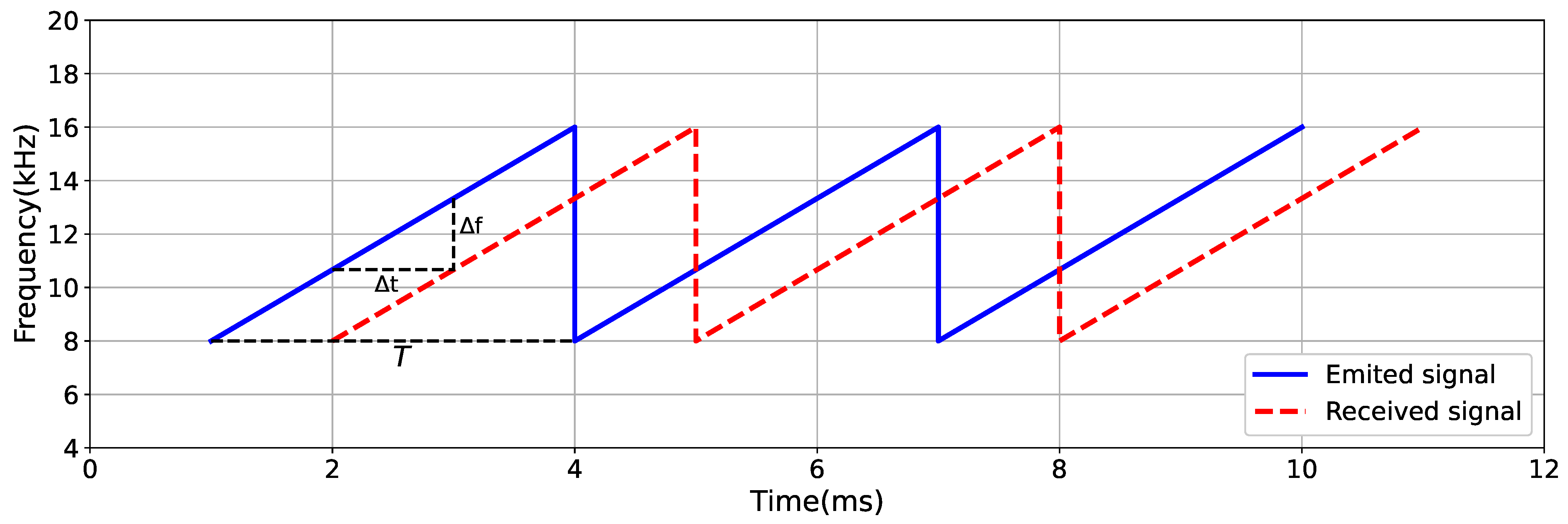
We adopt the Frequency Modulated Continuous Wave (FMCW) to generate signals (blue line in Figure 2). The frequency of acoustic signal should balance the physical capabilities of smartphones with background noises. The sound frequency of smartphone is usually between 110 Hz∼20 KHz, while the frequency of human voice is always less than 1 KHz. Experimental proof that the wider frequency range, the more pronounced the echo peak. In addition, low-frequency sounds travel further than high-frequency sounds under the same emission energy. Therefore, we generate the duration of acoustic signal as 3 ms and its frequency range is 8 KHz∼16 KHz.

3.1.2. Delay of Echo Signal

When the emitted acoustic signal meets the wall, its echo signal is reflected back and received via the smartphone’s microphone. At this time, the waveform of the received signal and the emitted signal are consistent, with a time delay of Δ t , as shown in Figure 2. In particular, the time delay Δ t is calculated as:
Δ t = Δ f · T f m a x f m i n
where f m i n represents the minimum frequency of the emitted signal, f m a x represents the maximum frequency of the emitted signal, and T represents the duration of the emitted signal.

3.1.3. Distance to Wall

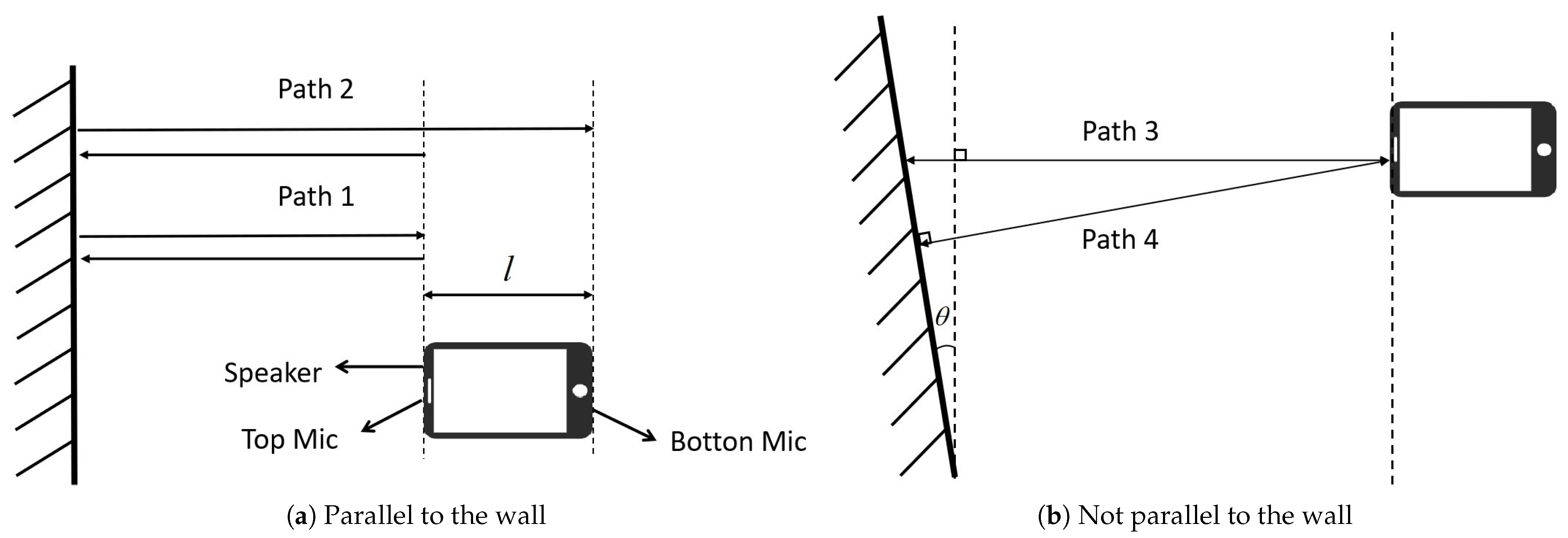
Figure 3a shows that when a user holds the smartphone horizontally while walking, Path 1 represents the transmission path of the signal received by the top microphone, and Path 2 represents the transmission path of the signal received by the bottom microphone. The difference in transmission distance of received signals between the two microphones is the length l of the smartphone. Thus, when the distance difference between the side-wall measured by two microphones is near 1 2 l , the signal received is probably the echo reflected from the wall.
The distance d from the wall to the smartphone (by its top microphone in Figure 3a) is expressed as:
d = 1 2 Δ t · v s o u n d
where v s o u n d is the sound propagation speed.
When the smartphone is not parallel to the wall, the distance detected is the vertical distance between the top microphone and the wall (Path 4 in Figure 3b), instead of the distance to the top of the smartphone (Path 3 in Figure 3b). Therefore, the exact distance can also be measured when the smartphone is not parallel to the wall.
When the acoustic wave encounters an obstacle, it will return and be received by the smartphone. When the volume of the obstacle is relatively small, it will be eliminated as an outlier during map refinement; When the obstacle is extremely large, it will be regarded as an indoor inaccessible area. Thus, the impact of nlos issues in acoustic ranging is reduced by our map refinement algorithm.

3.2. Inertial Tracking

In order to generate the trajectory, we devise an LSTM-based dead-reckoning method to track walking users in real time.

3.2.1. Step Counting

Step count is computed by detecting the peak and valley values of vertical accelerations. On the basis of our experiments, we set the peak-valley difference threshold to be 3 m/s 2 , and set the interval time between two steps to be 400 ms to avoid errors caused by hand-shaking.

3.2.2. Step Length Inference

We gather outdoor walking trajectories to train the step length for each user, with GPS records as the ground truth. First, we gather outdoor walking trajectories to train the step length for each user, with GPS records as the ground truth. We calculate the eigenvalues of each step along the 3-axis accelerometer and gyroscope including time and frequency domain features. Time domain features are composed of maximum, minimum, mean, and standard deviation. The frequency features are obtained by the fast Fourier transform, including the mean, standard deviation, information entropy, energy, skewness, and kurtosis.
Second, we propose an LSTM model for dead-reckoning (Figure 4). (1) The embedding layer aims to extract and fuse motion features of accelerometer and gyroscope. In particular, it adopts a two-layer fully connected network, with the dimensions of hidden layer and output layer as 64 and 128, respectively. We also stack a symmetric two-layer fully connected network, with the dimensions of hidden layer and output layer as 64 and 32, to further fuse accelerometer and gyroscope features, respectively. (2) The representation layer uses the cyclic neural network LSTM, with hidden layer of 128 dimensions. (3) The regression layer takes the output of the representation layer and the starting speed of each step as inputs, and adopts a full connected network with three layers to produce the length of this step. The dimension of each hidden layer is 64, 32, and 16, respectively.
In addition, each user trains a customized model to predict his/her individual step length when walking indoors.

3.2.3. Heading Orientation Estimation

To remove gyroscope drift and magnetometer noise, we compute the smartphone’s orientation by g a m e r v API for robustness purposes.

3.3. Map Construction and Refinement

3.3.1. Floor Plan Refinement

The wall segment are represented by scattered points on the map, and distances are measured based on user’s trajectory. Such floor plan is inconsistent with the actual map and contains extreme outliers.
Intuitively, most of the walls consist of line segments, and their intersections could be identified by turning events of the walking user. Once the detected windows and doors are removed, we fit the rest points as line segments, i.e.,
f ( x ) = k x + b
where k represents the gradient and b is the offset. To minimize the errors between a wall segment and the scattered points, we construct the objective function as:
e = i n ( k x i + b y i )
where e is the sum of errors, n is the number of points on the wall, ( x i , y i ) represents the ordinate of the i t h point by distance measurement. To minimize e, we compute the partial derivatives of k and b, respectively:
e k = 2 ( i n ( k x i + b y i ) x i ) = 0
e b = 2 ( i n ( k x i + b y i ) ) = 0
thus
k = i n ( x i y i ) n xy ¯ i n ( x i ) 2 n x ¯ 2
b = y ¯ k x ¯
where x ¯ represents the mean value. We, therefore, refine the reconstructed floor plan with wall segments, doors/windows, and corners.

3.3.2. Door and Window Detection

We measure the presence of windows and doors by detecting the distance variation between the smartphone and the side walls. When the change exceeds the threshold of 20   cm , we consider the point as a door/window. When the length of door/window is shorter than 5   cm , we regard them as outliers and eliminate them.

3.3.3. Connection Area Detection

In order to show the stereoscopic structure of the multi-level modern buildings, we test the connection areas between different floors, including stairs and elevators.
Stair Detection. Instinctively, when we climb stairs, our acceleration always varies a lot. To eliminate the effect of smartphone’s attitude, we calculate the amplitude value of the smartphone by triaxial acceleration (Figure 5a). Then, we use a sliding window to dynamically detect the peaks and valleys along the acceleration sequence. In order to avoid errors caused by handshakes, we set the minimum time interval between peak and valleys to 400 ms. Because, when holding a smartphone, it can take a step in a second. At the same time, the acceleration change of descending stairs is greater than that of descending stairs. Therefore, users can be determined to enter a higher or lower floor by distinguishing ascending and descending stairs.
Elevator Detection. When taking the elevator, the acceleration in the direction of gravity of the smartphone will change significantly. Figure 5b,c shows that When the elevator descends, the vertical acceleration decreases, and when the elevator rises, the vertical acceleration increases. Therefore, it can be determined that the user has entered a higher or lower floor by distinguishing the up and down of the elevator. We adopt a sliding window of 3 s to detect its rising/sinking interval, and verify that the two periods are within a reasonable time interval of 30 s.

4. Indoor Navigation

Based the constructed indoor floor plan by Batmapper-Plus, we present our dynamic time warping (DTW) mechanism which produces real-time navigation guidance for new mobile users. Intuitively, the DTW is a dynamic programming algorithm which has been widely used for voice recognition [8,9].

4.1. Reference Sequence Construction

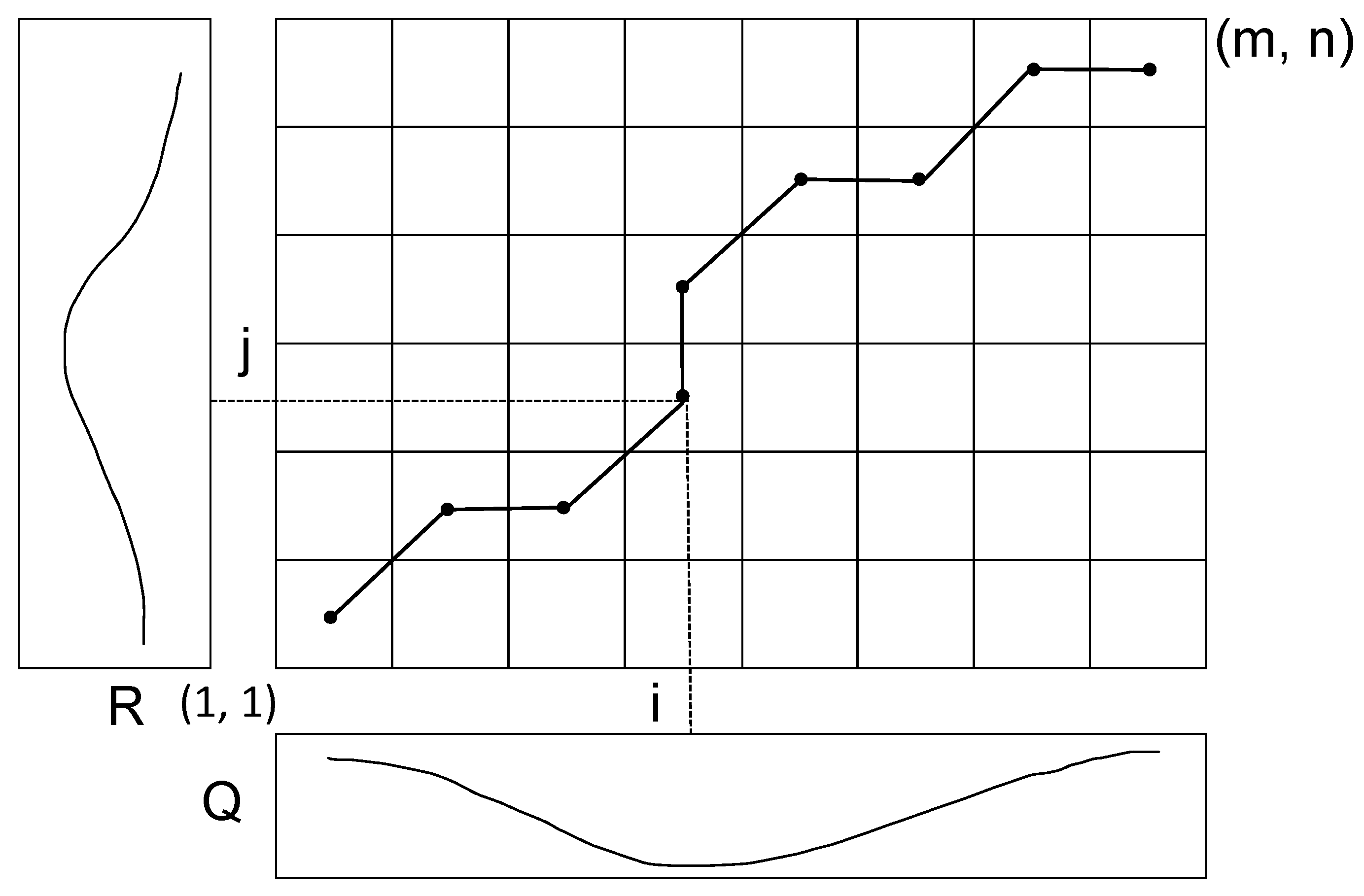
As shown in Figure 6, we suppose there are two time series, R and Q, with length m and n respectively. In order to match two sequences, a matrix is maintained in the algorithm, i.e., element ( i , j ) in the matrix is used to store the distance between point r i and point q j . Here, we compute the Euclidean distance, i.e.,
d ( i , j ) = ( r i q j ) 2
The purpose of our DTW algorithm is to find a path from ( 1 , 1 ) to ( m , n ) with the least cost. We define γ i , j as the minimum cumulative distance from point ( 1 , 1 ) to point ( i , j ) , thus
γ i , j = d ( r i , q j ) + m i n { γ i 1 , j , γ i , j 1 , γ i 1 , j 1 }
During the mapping process, the system automatically records the inertial readings during walking. We divide them by step counts, and construct the reference sequence R of DTW based on the mean value of three-axis gyroscope data in each step. In the navigation process, our system collects the user’s real-time IMU data as the query sequence Q, and matches it with the reference sequence R to find the corresponding forward direction at this moment. Note that the new user may walk into an incorrect fork from the navigation route, thus our system also records the wrong route as a reference sequence R b a c k to lead users back to the correct one.

4.2. DTW with Step Count Constraints

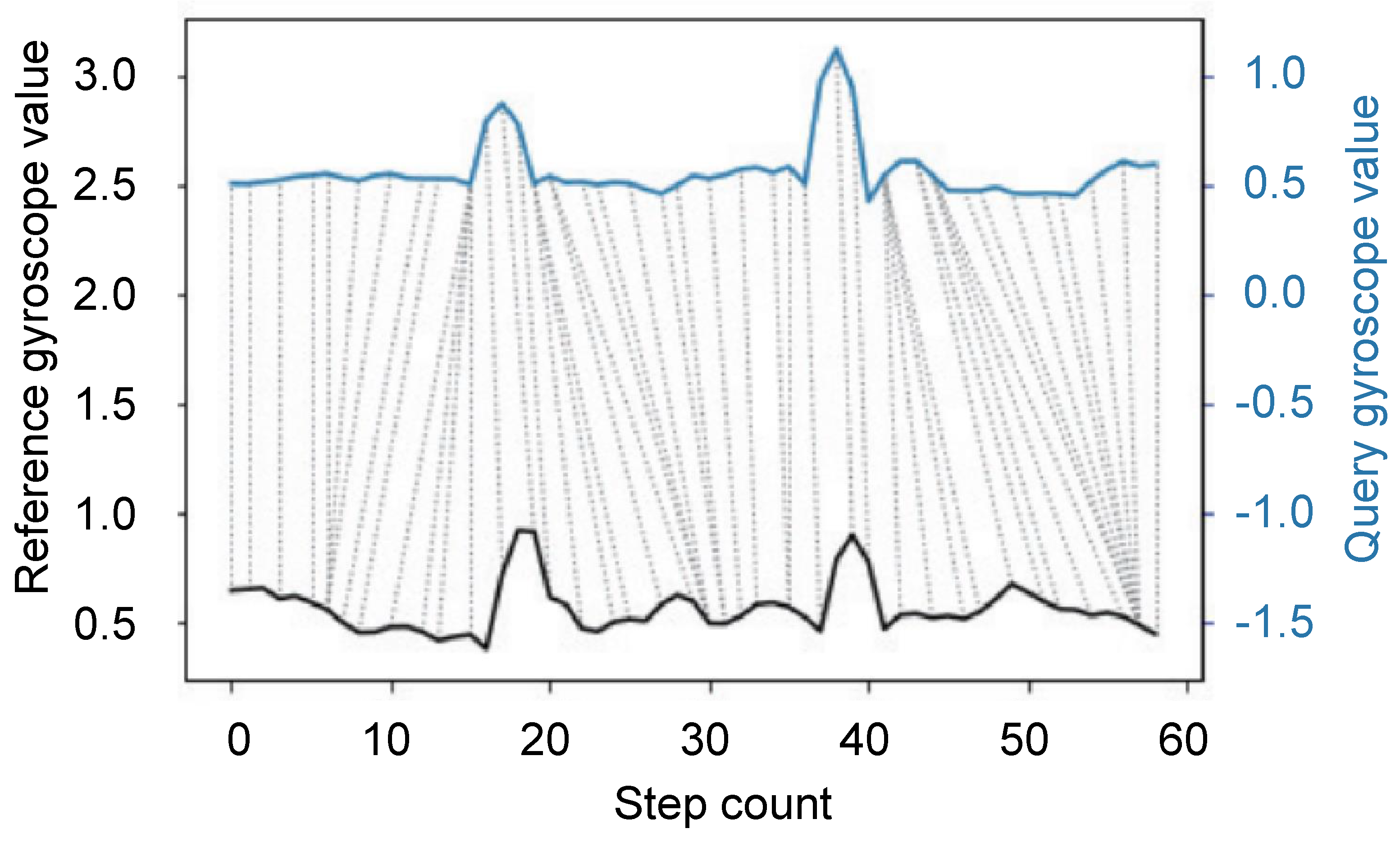
In order to navigate a newcome user, we aim to match his/her query sequence with the reference one. As shown in Figure 7, the upper and lower solid lines represent two step series, and the dotted lines between them show the associated points between two series. Both sequences are filtered by mean values to eliminate the influence of noise. DTW algorithm computes the sum of the normalized path distance between all these similar points to measure the similarity between two step series. To improve the matching accuracy, we use step counting to constrain the searching range in reference sequence. Since the step difference is generally no more than 5 steps along the same distance, we set the length of reference sequence L R as L Q + 5 , where L Q is the length of the query sequence. The user walks to update the query sequence in real time, and constantly matches similar points in the reference sequence. In addition, we use the forward orientation in reference sequence as the navigation guidance to users in real time. Our detailed DTW algorithm with step count constraints is shown in Algorithm 1.
Algorithm 1: DTW algorithm with step count constraints
Input: 
Reference gyroscope data g y r R [0...n-1], reference orientation data o r i R [0...n-1], query gyroscope data g y r Q [0...m-1]
Output: 
Navigation direction o r i n a v
1:
s t e p ← 0
2:
i n d e x ← 0
3:
while step % 2 = 0 do
4:
   Update g y r Q [0...m-1]
5:
    L Q = Len( g y r Q [0...m-1])
6:
    g y r R [0...n-1] = Reverse( g y r R [0...n-1])
7:
    o r i R [0...n-1] = Reverse( o r i R [0...n-1])
8:
    g y r R g y r R [0... L Q + 4 ] // Constrain reference sequence range
9:
   Calculate DTW cost matrix D by Equation 10 and record warping path
10:
   Calculate the first matching index i n d e x of o r i Q [ L Q 1 ] in warping path
11:
    o r i n a v = o r i R [ i n d e x ]
12:
   Output o r i n a v
13:
    s t e p = Pedometer() // Update step
14:
end while

4.3. Leading Back Incorrect Route

During navigation, the user may walk into a wrong fork from the navigation route. As shown in Figure 8, the user turns a corner at point B, resulting in a deviation from the correct route. In this case, the user’s walking sequence cannot match the reference sequence with accumulated errors. When the user deviates from the correct route for a certain distance, we judge it as a trajectory deviation and start leading back mechanism. Through experiments, we found that most of the deviations from the navigation route are greater than 10 m, so we set the threshold to 10 m in the system. The return guidance is still realized by a DTW algorithm, in which the incorrect route (from point B to point C) is used as the reference sequence for leading back. Thus, the user goes back to point B and continues to follow the navigation to reach the destination point D.

4.4. Trajectory Correction

As time goes by, the data of smartphone sensors will have large errors due to drift. To improve navigation trajectory accuracy, we propose a trajectory correction method based on linear fitting.
Usually the corner in the indoor navigation route is 90 degrees. The heading orientation changes gradually during turning, so we regard the position where the heading orientation changes more than 45 degrees in 2 s (to avoid noise impact) as a corner. We segment the trajectory according to the corner, then use the linear regression to fit the segmented trajectory. Calculate the heading orientation difference between the divided trajectory according to the slope of the fitting line. Finally, we rotate the trajectory around the starting point of the trajectory to obtain a more accurate trajectory. Figure 9 shows that the corrected trajectory is closer to the ground truth.

5. Results

The prototype of BatMapper-Plus was developed on Android and deployed on the MI 10S smartphone for the purpose of collecting data. We conducted experiments in a residential building and a teaching building, both of which are multi-level. A laser rangefinder was used to measure the true distance and floor plan. Our evaluation includes four aspects, i.e., unilateral acoustic ranging, floor plan construction, connection area detection, and indoor navigation.

5.1. Unilateral Acoustic Ranging

We evaluated acoustic ranging indoors for different user states and different distances to the wall.
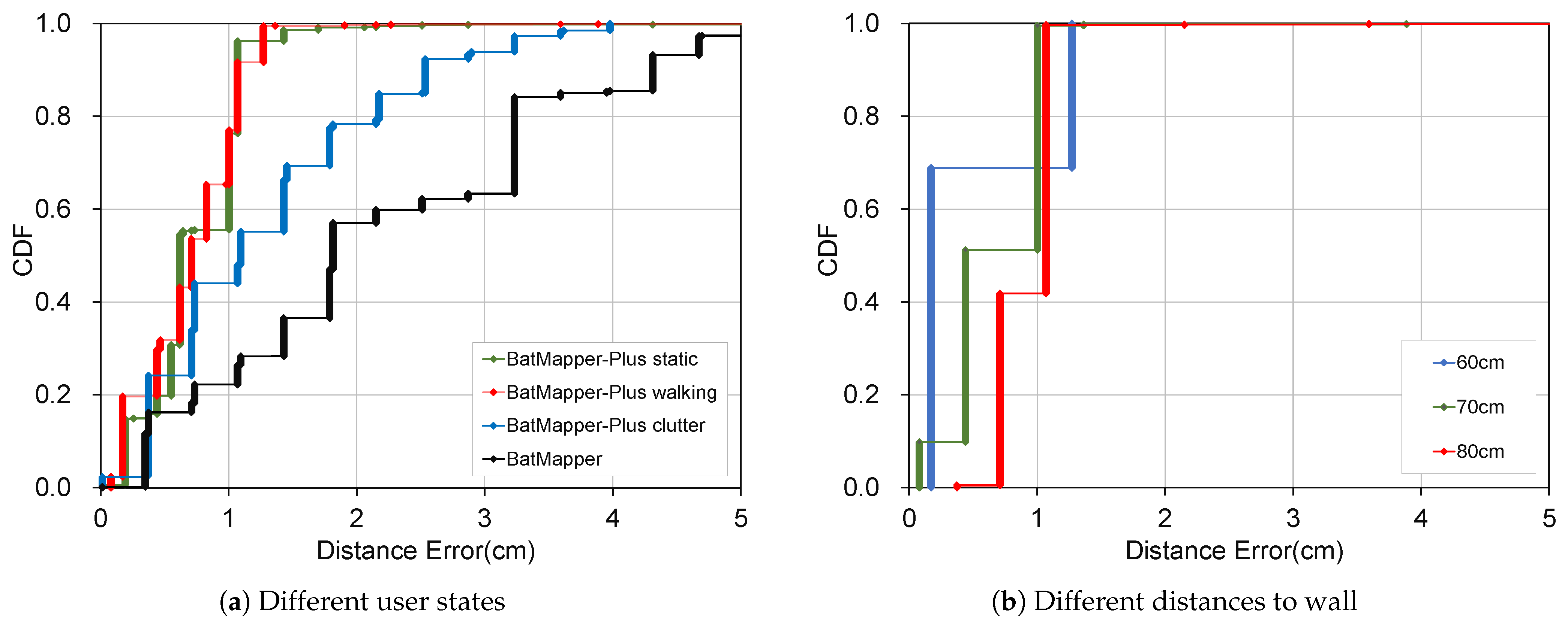
User states. In this paper, we test accuracy with static states, walking states, and a cluttered environment with many obstacles, and compare to BatMapper. Figure 10a shows that our distance measurement error in the static state is near that in walking state, with the median value around 0.7 cm and the maximum value less than 1.5 cm, both of which are obviously lower than the BatMapper. Accuracy drops slightly in a cluttered environment. These results demonstrate our effectiveness of unilateral ranging.
Distance to wall. Distances are tested at 60 cm, 70 cm, and 80 cm to the same wall. Figure 10b shows that all errors are less than 2 cm. Furthermore, the farther the distance, the greater the errors.

5.2. Floor Plan Construction

Construction effect. We illustrate the effects of floor plan construction in a classroom of 8.7 m × 6.3 m in teaching building, a living room of 7 m × 4.5 m, and a corridor of 6 m × 11 m in residential building, respectively. These three experimental scenarios contain multiple doors, windows, and blackboards/closets. The user holds the smartphone horizontally and walks along the boundary of the experimental scene to determines the location of the wall segments through acoustic ranging. Such scattered points are drawn on the map based on the walking trajectory (Figure 11b, Figure 12b and Figure 13b). Our refinement algorithm then improves the constructed floor plan (Figure 11c, Figure 12c and Figure 13c).
Quantitative results. To accurately assess the reconstructed floor plan, we overlay it on the ground truth in order to obtain the maximum overlap (Figure 14), and observe that the location errors of wall segments are all within 0.3 m. Then, we define the precision, recall, and F-score as follows:
P = S r e S g t S r e , R = S r e S g t S g t , F = 2 P · R P + R
where S r e represents the shape of reconstructed map, S g t represents the shape of the ground truth, and S r e S g t represents their overlap area.
Table 1 shows the quantitative results for the construction of the floor plan in the classroom, living room, and corridor. In comparison to BatMapper and CrowdInside [10], the recall and F-score of our BatMapper-Plus are significantly higher than that of the other methods, indicating that we are producing more accurate indoor maps. Since the floor plan of other methods is much smaller than the ground truth, their precision are higher.
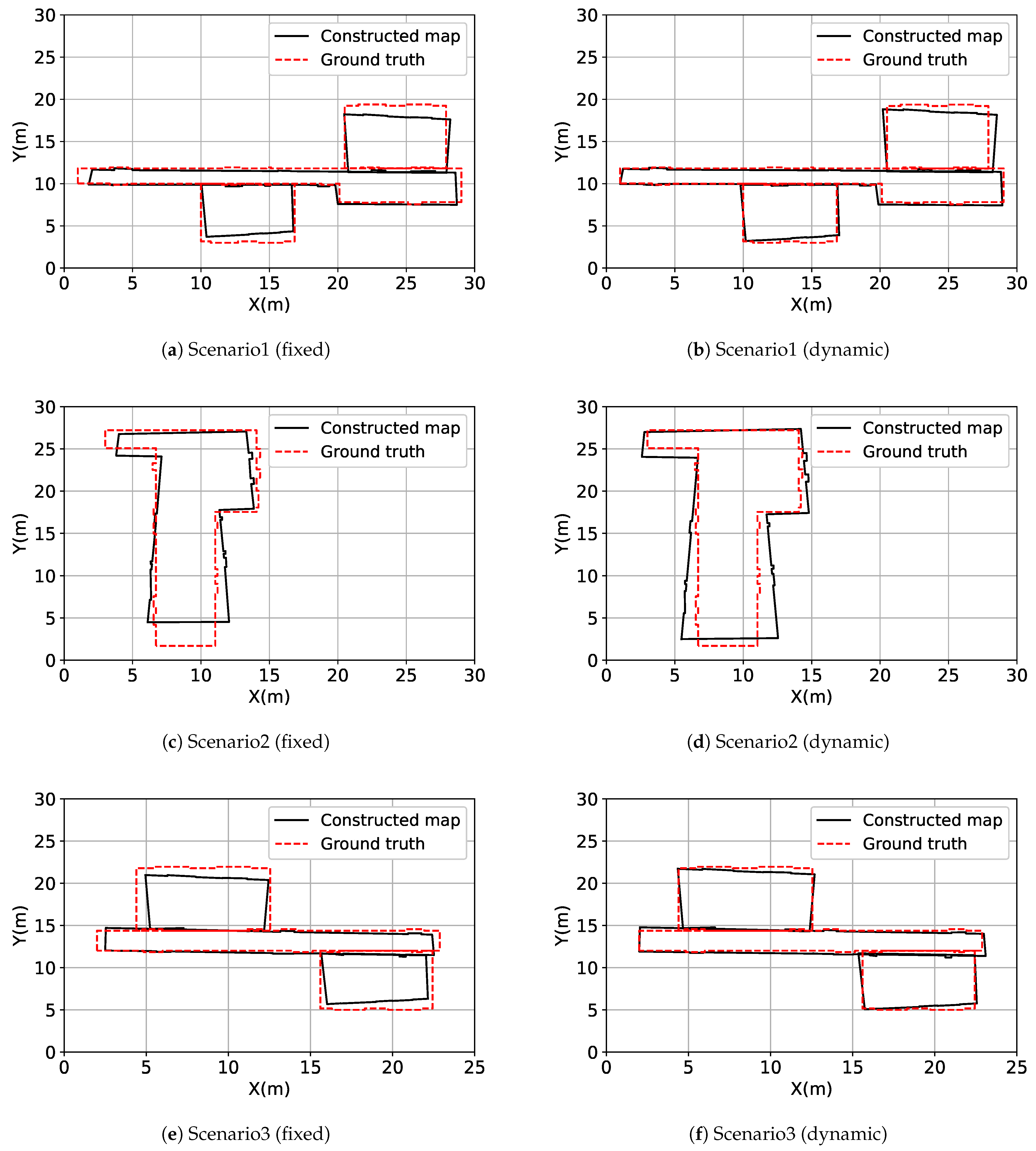
Step length inference. To evaluate the effectiveness of the dynamic step length mechanism, our evaluations include two items. (1) Map construction comparison between fix/dynamic step lengths. We have conducted experiments in three large-scale scenarios in a teaching building (Figure 15). In addition, Table 2 further shows that the dynamic step length has increased the average F-score values by 7.2%. (2) Step length inference accuracy. We have tested 10 trajectories, each around 40 m long, and the length errors of estimated trajectories are constantly less than 5 m (shown in Figure 16a).

5.3. Connection Area Detection

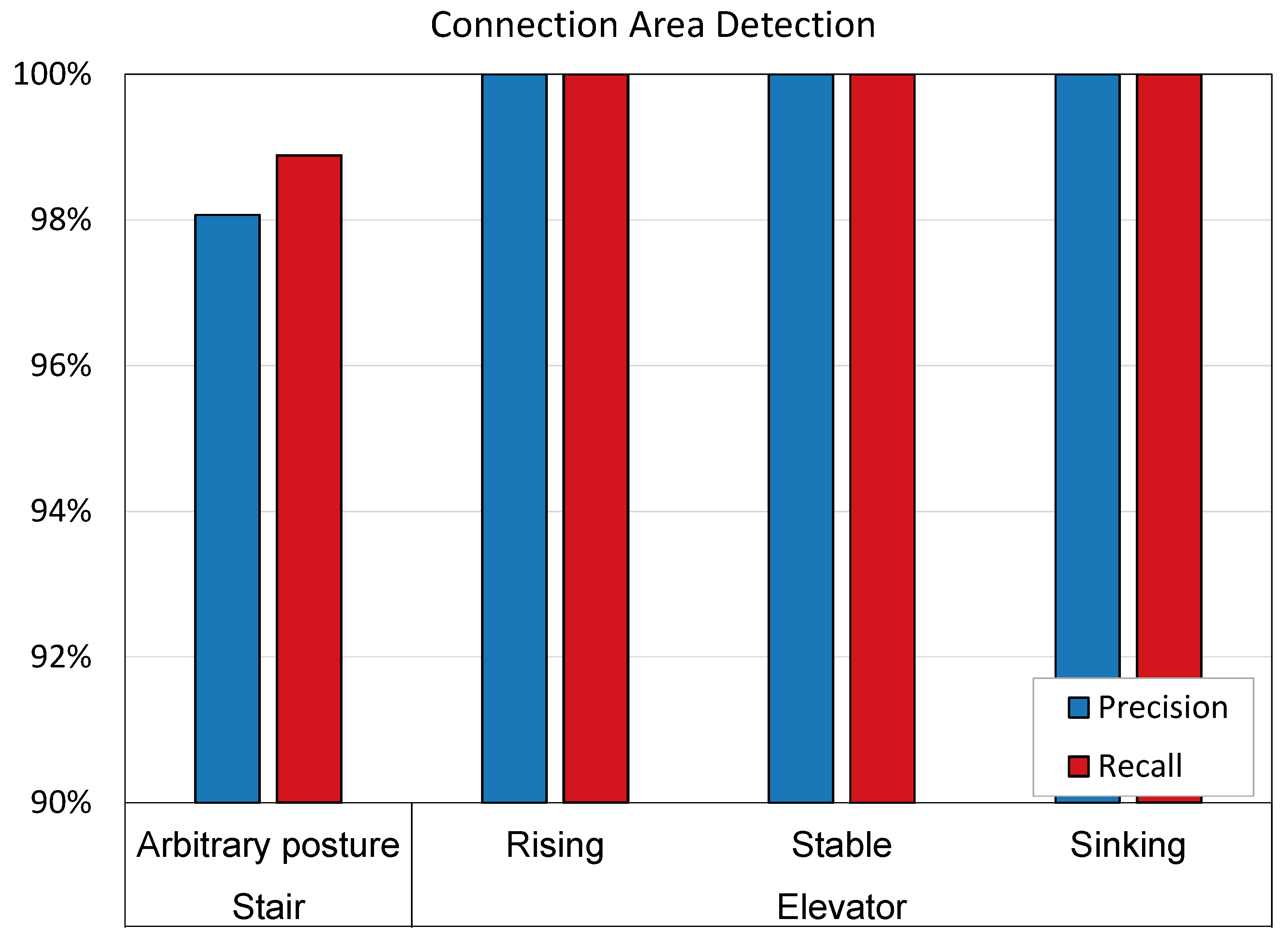
Stairs. To assess the accuracy of stair detection, we conduct several walkings which contain the ground and stairs with a length of 2 min, and we predict the location type for each walking step. Figure 17 shows that there are at most 6 incorrect steps in each walk, with a precision of 98% and a recall of 99%.
Elevator.Figure 17 shows that for a user standing statically, all states are correctly detected, so both the precision and the recall of the elevators detection are as high as 100%.

5.4. Consumption

We monitored the power consumption of BatMapper-Plus during many experiments in the teaching building. Many experiments have shown that the power consumption of BatMapper-Plus is less than 100 mAh/min, which is very small for smartphones. Therefore, this method has a low calculation cost.

5.5. Indoor Navigation

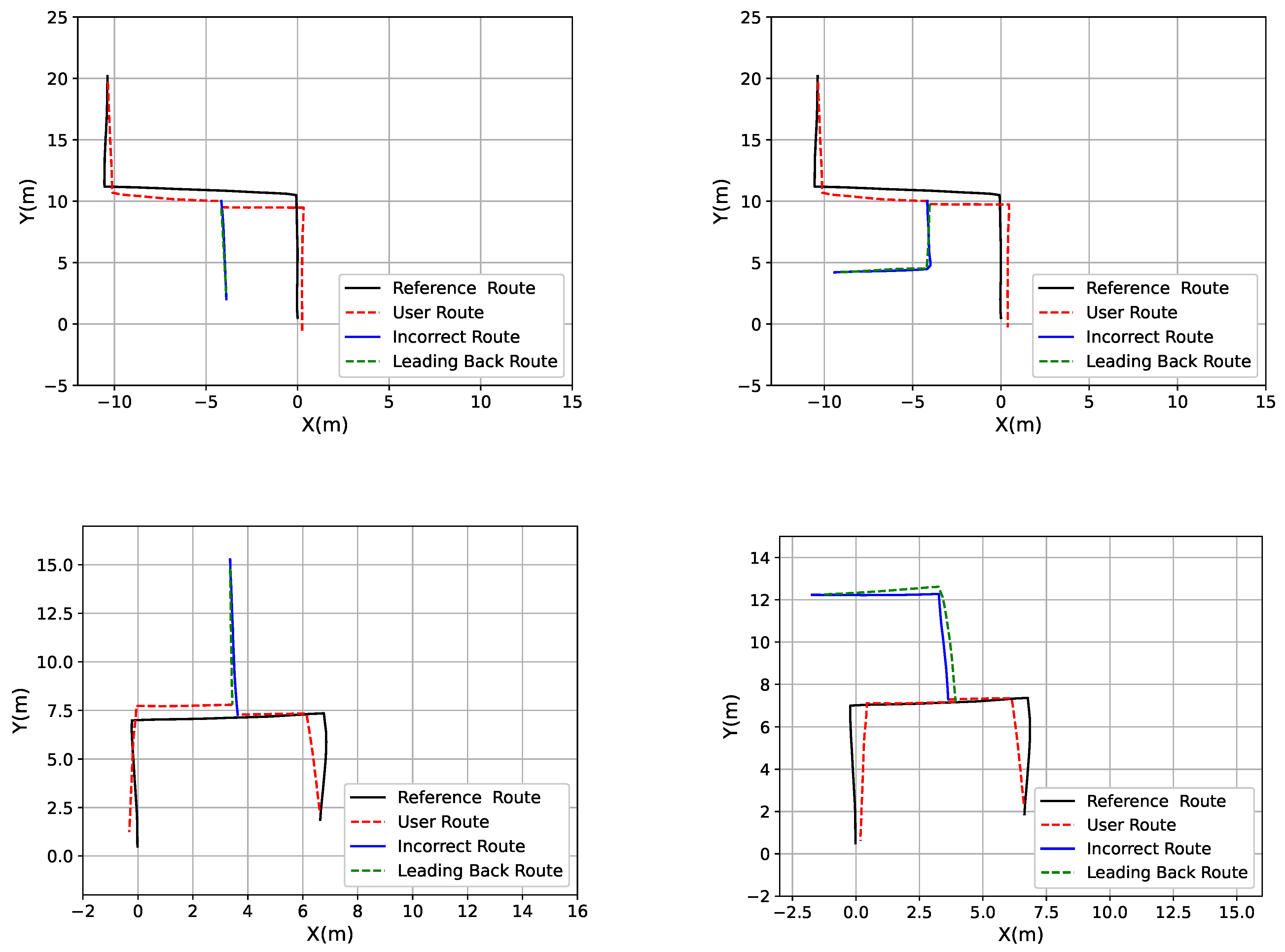
Based on the constructed floor plan by our BatMapper-Plus, we aim to demonstrate how to use the “new” map for indoor navigation. In particular, we have conducted navigation experiments in 15 indoor scenarios, and each scenario includes multiple straight lines and corners. In the navigation process, users walk into a deviated fork, then they are guided back to the correct route and finally reach the destination. Figure 16b shows location errors when users return the correct route, and Figure 16c shows location errors when users reach the terminal. All location errors are less than 1.5 m, and some example navigation paths with leading back routes are shown in Figure 18.

6. Discussion

The high-cost of high-precision instruments and the visual method is affected by the lighting conditions and has the risk of privacy leakage, making sound wave a better choice to restore the indoor structure.

6.1. Indoor Floor Plan Construction

We use the FMCW to replace the original acoustic wave of BatMapper. In various environments, the ranging accuracy has been significantly improved, as shown in Figure 10. We also propose a floor plan refinement algorithm to convert the scattered indoor floor plan into a complete one, which not only eliminates abnormal points and fills in missing information, but also makes the plan structure more consistent with the real plan structure. In order to represent the multi-level structure in the building, we propose a detection method for stairs and elevators, which increases the three-dimensional structure of the indoor floor plan.

6.2. Indoor Navigation

The indoor navigation method based on BatMapper-Plus plan proposed by us uses DTW algorithm to provide navigation for users. This method not only has low cost and high precision, but also provides the function of incorrect route leading back. To reduce the impact of sensor errors, we propose a trajectory correction method to make the trajectory more accurate.

7. Related Work

7.1. Indoor Floor Plan Construction

Currently, indoor floor plan construction is primarily achieved through the combination of image and inertial sensors. Jigsaw [4] uses image, inertial sensor data, user’s trajectory and the position of the captured image to construct the floor plan. Plansketcher [11] constructs the indoor floor plan by deep learning technology. Ref. [12] combines the magnetic fingerprint map and the trajectory of the user to construct the interior floor plan. IndoorCrowd2D [13] restores the building’s structure by using the image information and sensory data in crowdsourcing data. RTSDM [14] uses the UAV system to distinguish its location and environment, and then build a three-dimensional map.

7.2. Acoustic Ranging

Acoustic ranging is gradually applied to indoor positioning and navigation. DeepRange [15] employs a deep neural network for distance estimation. Ref. [16] maintains high ranging accuracy by an improved TOA estimation method.

7.3. Inertial Tracking

There is multitudinous related research about indoor tracking, primarily use image and inertial sensors. Walkie-Markie [17] uses Wi-Fi tags and inertial sensor data to construct the user’s trajectories. Zee [18] makes use of inertial sensors and Wi-Fi cues for tracking. VeTrack [19] makes use of the mobile phone’s inertial sensor to track the vehicle’s position in real-time. Ref. [20] uses inertial sensors and magnetometers to measure the step length and determine the heading direction to achieve pedestrian tracking. Ref. [21] proposes a model for signal interference identification and positioning error compensation, which solves the problem of UWB indoor positioning with signal interference.

7.4. Indoor Navigation

Nowadays, the mainstream indoor navigation methods mainly use image, inertial navigation system(INS), Wi-Fi, and Bluetooth for positioning and navigation. Ref. [22] uses the magnetic field fluctuations in the building to create a magnetic map for indoor positioning. Ref. [23] fuses PDR and Wi-Fi signal to correct the drift in navigation and achieve effective positioning and navigation. Ref. [24] proposes multiple neural networks which are customized to the user’s location, and achieves cost-effective indoor navigation with Bluetooth architecture. DLoc [25] is a wireless location algorithm based on deep learning, which overcomes the traditional limitations of RF-based location methods. Ref. [26] designs an asynchronous position measurement system which uses transmitter and receiver to calculate TOA for indoor positioning. Ref. [27] realizes indoor navigation through intelligent integration of inertial odometer, crowdsourcing Wi-Fi fingerprint and indoor map information. Ref. [28] uses smartphone cameras to detect signs on the ceiling of buildings to provide user navigation.

8. Conclusions

In this paper, we propose BatMapper-Plus which use unilateral acoustic ranging to construct multi-level indoor floor plans without the need for heavy human efforts and privacy/copyright concerns. Our unilateral ranging technique eliminates the limitation of bilateral ranging and realizes precise distance measurements with errors of less than 2 cm. To replace scattered points, we further refine the reconstructed map with line segments, and identify connection areas among different floors. In addition, we propose an indoor navigation mechanism which uses the constructed map to provide fine-grained navigation for indoor users. We build a prototype and conduct experiments in multiple buildings, and the results have shown our effectiveness.

Author Contributions

Conceptualization, C.M. and R.G.; methodology, C.M. and R.G.; software, C.M. and S.J.; validation, C.M., S.J. and M.W.; formal analysis, X.X.; investigation, M.W.; data curation, S.J.; writing—original draft preparation, R.G. and C.M.; writing—review and editing, R.G.; visualization, S.J.; supervision, D.T.; project administration, D.T.; funding acquisition, R.G. All authors have read and agreed to the published version of the manuscript.

Funding

This work was supported in part by NSFC under Grant 62072029 and Grant 61872027, DiDi Research Collaboration Plan, and OPPO Research Fund.

Data Availability Statement

Not applicable.

Conflicts of Interest

The authors declare no conflict of interest.

References

  1. Wang, X.; Marcotte, R.J.; Olson, E. GLFP: Global localization from a floor plan. In Proceedings of the IEEE/RSJ International Conference on Intelligent Robots and Systems (IROS), Venetian Macao, Macau, 3–8 November 2019; pp. 1627–1632. [Google Scholar]
  2. Anderson, R.; Curro, J. Indoor Navigation Using Convolutional Neural Networks and Floor Plans. In Proceedings of the ION GNSS+, Denver, CO, USA, 19–23 September 2021; pp. 2133–2150. [Google Scholar]
  3. Harithas, S.S.; Pardia, B. GenNav: A Generic Indoor Navigation System for Mobile Robots. In Proceedings of the IEEE I-SMAC, Palladam, India, 7–9 October 2020; pp. 182–187. [Google Scholar]
  4. Gao, R.; Zhao, M.; Ye, T.; Ye, F.; Luo, G.; Wang, Y.; Bian, K.; Wang, T.; Li, X. Multi-story indoor floor plan reconstruction via mobile crowdsensing. IEEE Trans. Mob. Comput. 2016, 15, 1427–1442. [Google Scholar] [CrossRef]
  5. Zhou, B.; Elbadry, M.; Gao, R.; Ye, F. BatMapper: Acoustic sensing based indoor floor plan construction using smartphones. In Proceedings of the ACM MobiSys, Niagara Falls, NY, USA, 19–23 June 2017; pp. 42–55. [Google Scholar]
  6. Meng, C.; Jiang, S.; Wu, M.; Xiao, X.; Tao, D.; Gao, R. BatMapper-Plus: Smartphone-Based Multi-level Indoor Floor Plan Construction via Acoustic Ranging and Inertial Sensing. In Proceedings of the International Conference on Wireless Algorithms, Systems, and Applications, Dalian, China, 24–26 November 2022; Springer: Cham, Switzerland; pp. 155–167. [Google Scholar]
  7. Pradhan, S.; Baig, G.; Mao, W.; Qiu, L.; Chen, G.; Yang, B. Smartphone-based acoustic indoor space mapping. Proc. ACM Interact. Mob. Wearable Ubiquitous Technol. 2018, 2, 1–26. [Google Scholar] [CrossRef]
  8. Keogh, E.; Ratanamahatana, C.A. Exact indexing of dynamic time warping. Knowl. Inf. Syst. 2005, 7, 358–386. [Google Scholar] [CrossRef]
  9. Plouffe, G.; Cretu, A.M. Static and dynamic hand gesture recognition in depth data using dynamic time warping. IEEE Trans. Instrum. Meas. 2015, 65, 305–316. [Google Scholar] [CrossRef]
  10. Alzantot, M.; Youssef, M. Crowdinside: Automatic construction of indoor floorplans. In Proceedings of the 20th International Conference on Advances in Geographic Information Systems, Redondo Beach, CA, USA, 6–9 November 2012; pp. 99–108. [Google Scholar]
  11. Peng, Z.; Gao, S.; Xiao, B.; Wei, G.; Guo, S.; Yang, Y. Indoor floor plan construction through sensing data collected from smartphones. IEEE Internet Things J. 2018, 5, 4351–4364. [Google Scholar] [CrossRef]
  12. Luo, H.; Zhao, F.; Jiang, M.; Ma, H.; Zhang, Y. Constructing an indoor floor plan using crowdsourcing based on magnetic fingerprinting. Sensors 2017, 17, 2678. [Google Scholar] [CrossRef] [PubMed]
  13. Chen, S.; Li, M.; Ren, K.; Fu, X.; Qiao, C. Rise of the indoor crowd: Reconstruction of building interior view via mobile crowdsourcing. In Proceedings of the ACM SenSys, Seoul, Republic of Korea, 1–4 November 2015; pp. 59–71. [Google Scholar]
  14. Li, Z.; Zhao, J.; Zhou, X.; Wei, S.; Li, P.; Shuang, F. RTSDM: A Real-Time Semantic Dense Mapping System for UAVs. Machines 2022, 10, 285. [Google Scholar] [CrossRef]
  15. Mao, W.; Sun, W.; Wang, M.; Qiu, L. DeepRange: Acoustic ranging via deep learning. Proc. ACM Interact. Mob. Wearable Ubiquitous Technol. 2020, 4, 1–23. [Google Scholar] [CrossRef]
  16. Liu, Z.; Chen, R.; Ye, F.; Guo, G.; Li, Z.; Qian, L. Improved TOA estimation method for acoustic ranging in a reverberant environment. IEEE Sens. J. 2020, 22, 4844–4852. [Google Scholar] [CrossRef]
  17. Shen, G.; Chen, Z.; Zhang, P.; Moscibroda, T.; Zhang, Y. {Walkie-Markie}: Indoor Pathway Mapping Made Easy. In Proceedings of the USENIX NSDI, Lombard, IL, USA, 2–5 April 2013; pp. 85–98. [Google Scholar]
  18. Rai, A.; Chintalapudi, K.K.; Padmanabhan, V.N.; Sen, R. Zee: Zero-effort crowdsourcing for indoor localization. In Proceedings of the ACM MobiCom, Istanbul, Turkey, 22–26 August 2012; pp. 293–304. [Google Scholar]
  19. Zhao, M.; Ye, T.; Gao, R.; Ye, F.; Wang, Y.; Luo, G. Vetrack: Real time vehicle tracking in uninstrumented indoor environments. In Proceedings of the ACM SenSys, Seoul, Republic of Korea, 1–4 November 2015; pp. 99–112. [Google Scholar]
  20. Zhang, Z.Q.; Meng, X. Use of an inertial/magnetic sensor module for pedestrian tracking during normal walking. IEEE Trans. Instrum. Meas. 2014, 64, 776–783. [Google Scholar] [CrossRef] [Green Version]
  21. Ma, J.; Duan, X.; Shang, C.; Ma, M.; Zhang, D. Improved Extreme Learning Machine Based UWB Positioning for Mobile Robots with Signal Interference. Machines 2022, 10, 218. [Google Scholar] [CrossRef]
  22. Gozick, B.; Subbu, K.P.; Dantu, R.; Maeshiro, T. Magnetic maps for indoor navigation. IEEE Trans. Instrum. Meas. 2011, 60, 3883–3891. [Google Scholar] [CrossRef]
  23. Evennou, F.; Marx, F. Advanced integration of WiFi and inertial navigation systems for indoor mobile positioning. EURASIP J. Adv. Signal Process. 2006, 2006, 1–11. [Google Scholar] [CrossRef]
  24. Altini, M.; Brunelli, D.; Farella, E.; Benini, L. Bluetooth indoor localization with multiple neural networks. In Proceedings of the IEEE 5th International Symposium on Wireless Pervasive Computing, Modena, Italy, 5–7 May 2010; pp. 295–300. [Google Scholar]
  25. Ayyalasomayajula, R.; Arun, A.; Wu, C.; Sharma, S.; Sethi, A.R.; Vasisht, D.; Bharadia, D. Deep learning based wireless localization for indoor navigation. In Proceedings of the 26th Annual International Conference on Mobile Computing and Networking, London, UK, 21–25 September 2020; pp. 1–14. [Google Scholar]
  26. Zhou, Y.; Law, C.L.; Guan, Y.L.; Chin, F. Indoor elliptical localization based on asynchronous UWB range measurement. IEEE Trans. Instrum. Meas. 2010, 60, 248–257. [Google Scholar] [CrossRef]
  27. Xu, C.; Liu, Z.; Li, Z. Robust visual-inertial navigation system for low precision sensors under indoor and outdoor environments. Remote Sens. 2021, 13, 772. [Google Scholar] [CrossRef]
  28. Khan, D.; Ullah, S.; Nabi, S. A generic approach toward indoor navigation and pathfinding with robust marker tracking. Remote Sens. 2019, 11, 3052. [Google Scholar] [CrossRef] [Green Version]
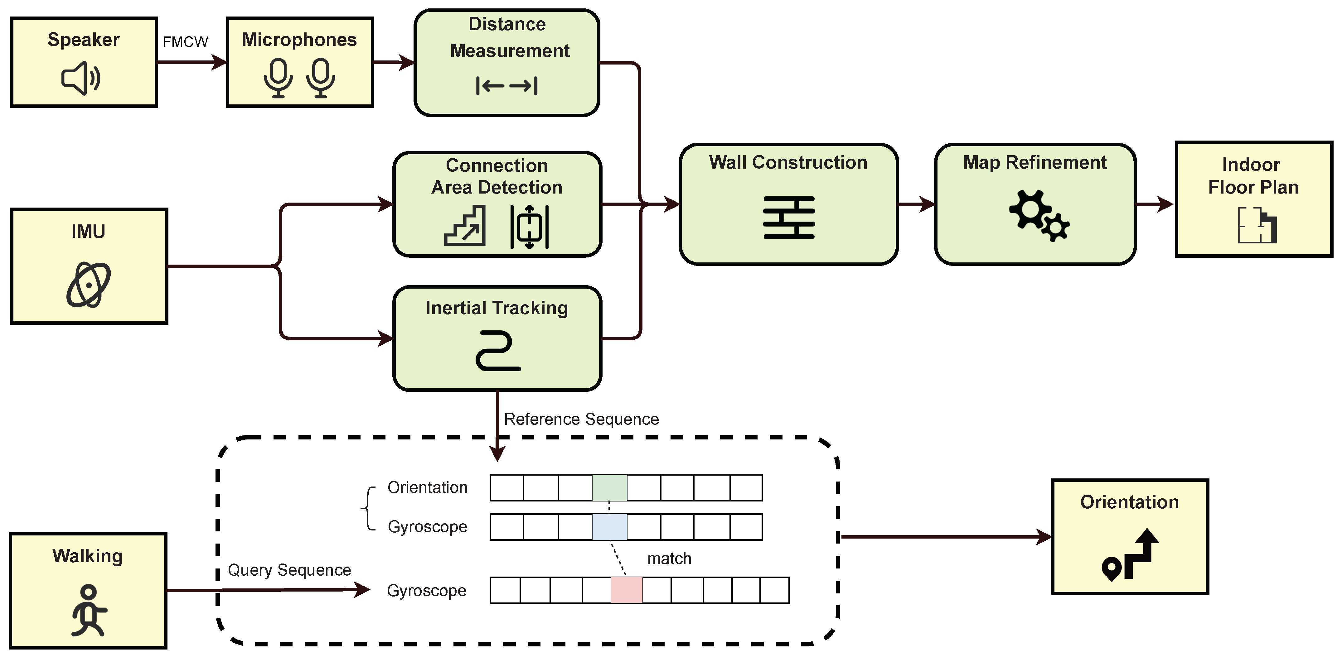
Figure 1. Overview of BatMapper-Plus. Distance measurement: we use smartphone’s speaker to emit FMCW sound signals, and use microphones to receive the signals returned by the side wall, then we calculate the distance between the smartphone and the wall according to the sound propagation time. Inertial tracking: we use IMU readings to estimate the user’s walking trajectory and detect connection areas among different levels. Sequence matching: the IMU record stored in the mapping process is used as the reference sequence, and we devise a DTW algorithm to match the reference sequence with new user’s walking sequence to provide fine-grained navigation guidance.
Machines 11 00205 g001
Figure 2. Emitted and received FMCW signals for distance calculation.
Machines 11 00205 g002
Figure 3. The position of the speaker and microphones, and the sound signal propagation path received by the microphone. (a) Sound signal propagation path when smartphone is parallel to the wall. (b) Sound signal propagation path when smartphone is not parallel to the wall.
Machines 11 00205 g003
Figure 4. LSTM-based dead-reckoning model structure. Its inputs include acceleration readings, gyroscope readings, and start speed at this step. Our model consists of three modules: the embedding layer, the representation layer, and the regression layer.
Machines 11 00205 g004
Figure 5. Variations of acceleration. (a) represents the change of acceleration data at the stair. (b) represents the change of acceleration data when an elevator rises. (c) represents the change of acceleration data when an elevator sinks.
Machines 11 00205 g005
Figure 6. Using the DTW algorithm to find the least-cost path in the cost matrix. R represents the reference sequence with a length of m, and Q represents the query sequence with a length of n.
Machines 11 00205 g006
Figure 7. Gyroscope data sequence matching. The blue line represents the reference sequence, the black line represents the query sequence, and the dotted line represents the similar points between two time series.
Machines 11 00205 g007
Figure 8. Incorrect route leading back. Path 1 and path 4 represent the correct navigation route, path 2 represents the incorrect route, and path 3 represents the leading back route.
Machines 11 00205 g008
Figure 9. Comparison with the ground truth and corrected trajectory.
Machines 11 00205 g009
Figure 10. Errors of unilateral acoustic ranging. (a) represents the ranging errors of the user in different states. (b) represents the ranging errors of the user in different environments.
Machines 11 00205 g010
Figure 11. Classroom construction process. (a) represents the real indoor plan. (b) represents the collected wall coordinate points. (c) represents the indoor plan constructed by the map refinement algorithm.
Machines 11 00205 g011
Figure 12. Living room construction process. (a) represents the real indoor plan. (b) represents the collected wall coordinate points. (c) represents the indoor plan constructed by the map refinement algorithm.
Machines 11 00205 g012
Figure 13. Corridor construction process. (a) represents the real indoor plan. (b) represents the collected wall coordinate points. (c) represents the indoor plan constructed by the map refinement algorithm.
Machines 11 00205 g013
Figure 14. Comparison between reconstructed indoor floor plans and the ground truth. The red dotted line represents the real indoor plan, and the black solid line represents the indoor floor plan we built.
Machines 11 00205 g014
Figure 15. Comparison of indoor floor plan construction effect between dynamic step length and fixed step length of three scenarios in teaching buildings. (a,c,e) adopt fixed step length; and (b,d,f) adopt dynamic step length. The red dotted line represents the real floor plan, and the black solid line represents the indoor floor plan we constructed.
Machines 11 00205 g015
Figure 16. (a) is the errors of trajectory length with dynamic step length. (b) is the errors of leading back. (c) is the errors of destination.
Machines 11 00205 g016
Figure 17. Recall and precision of stair and elevator detection.
Machines 11 00205 g017
Figure 18. Route map of indoor navigation with leading back. The black solid line represents the reference route, the red dotted line represents the navigation route, the blue solid line represents the incorrect route, and the dotted green line represents the leading back route.
Machines 11 00205 g018aMachines 11 00205 g018b
Table 1. Evaluation of floor plans.
ScenarioClassroomLiving RoomCorridor
CriterionR (%)P (%)F (%)R (%)P (%)F (%)R (%)P (%)F (%)
CrowInside77.2810087.1874.8010085.5858.8210074.07
BatMapper96.3699.6197.9697.4696.2196.5884.7194.1289.17
BatMapper-Plus97.8999.4898.6899.0598.4698.7597.6591.7694.61
Table 2. Effect evaluation of dynamic step length.
ScenarioScenario1Scenario2Scenario3
CriterionR (%)P (%)F (%)R (%)P (%)F (%)R (%)P (%)F (%)
Fixed83.9396.7989.9083.2389.3286.1780.6697.9988.48
Dynamic93.0795.6194.3297.0079.0987.1394.6596.0595.35
Disclaimer/Publisher’s Note: The statements, opinions and data contained in all publications are solely those of the individual author(s) and contributor(s) and not of MDPI and/or the editor(s). MDPI and/or the editor(s) disclaim responsibility for any injury to people or property resulting from any ideas, methods, instructions or products referred to in the content.