
Takagi–Sugeno Fuzzy Model-Based Control for Semi-Active Cab Suspension Equipped with an Electromagnetic Damper and an Air Spring

 and
and
Abstract
:1. Introduction
2. Quarter-Cab Car Suspension with A-EMD
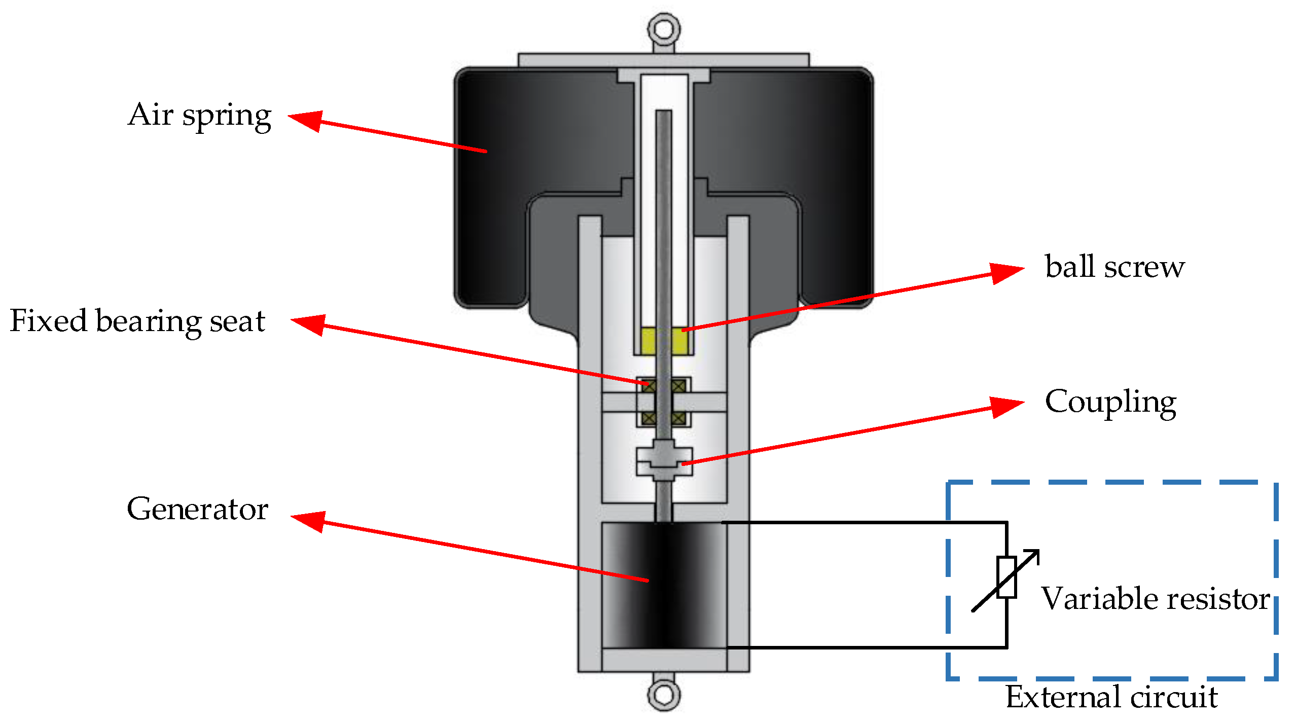
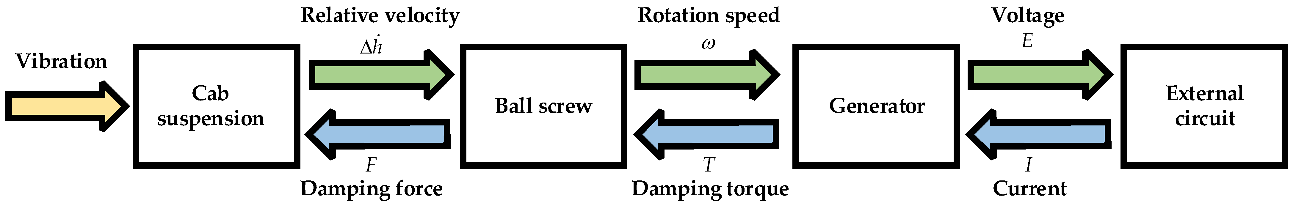
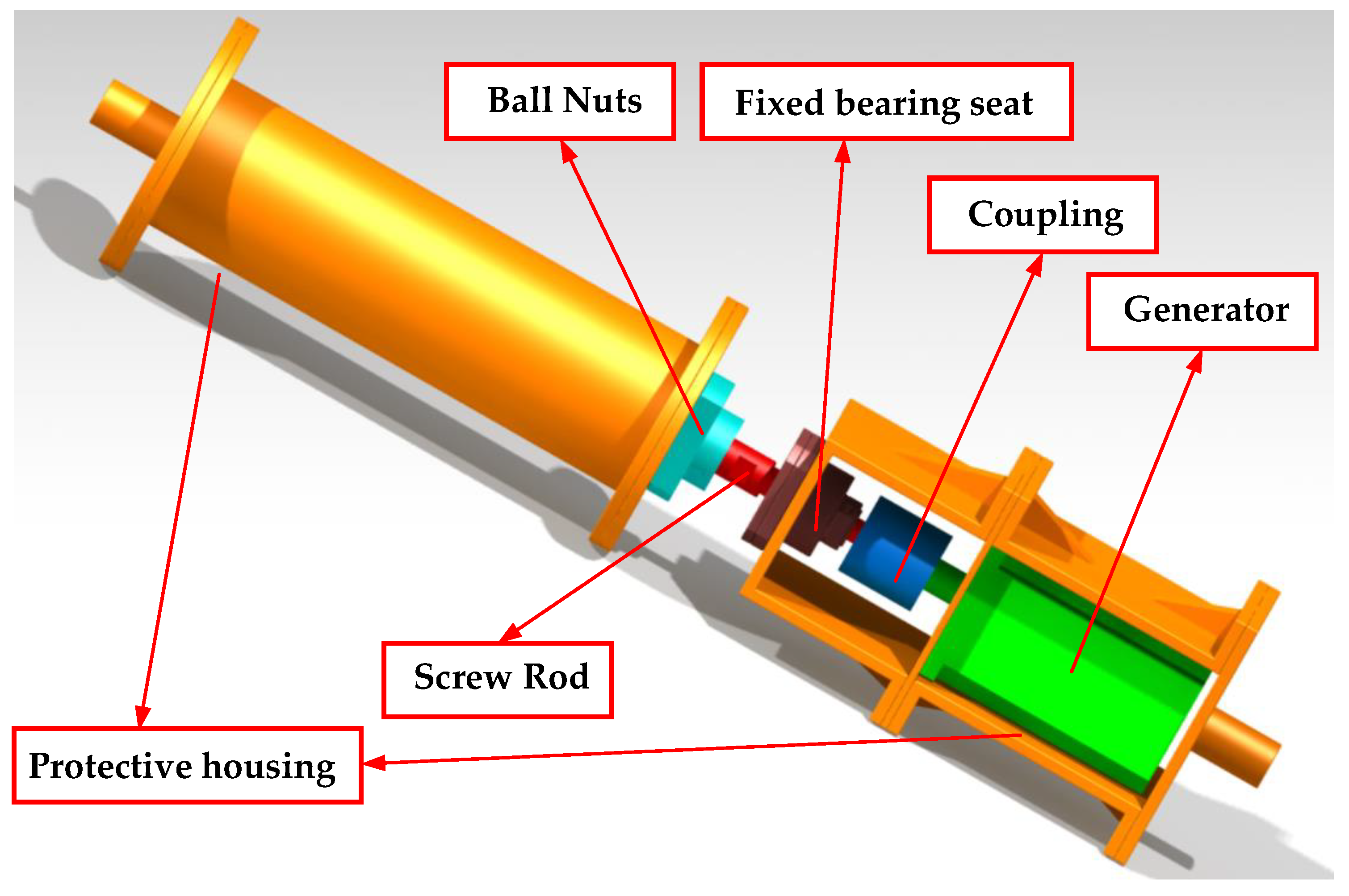
2.1. The Working Principle of A-EMD
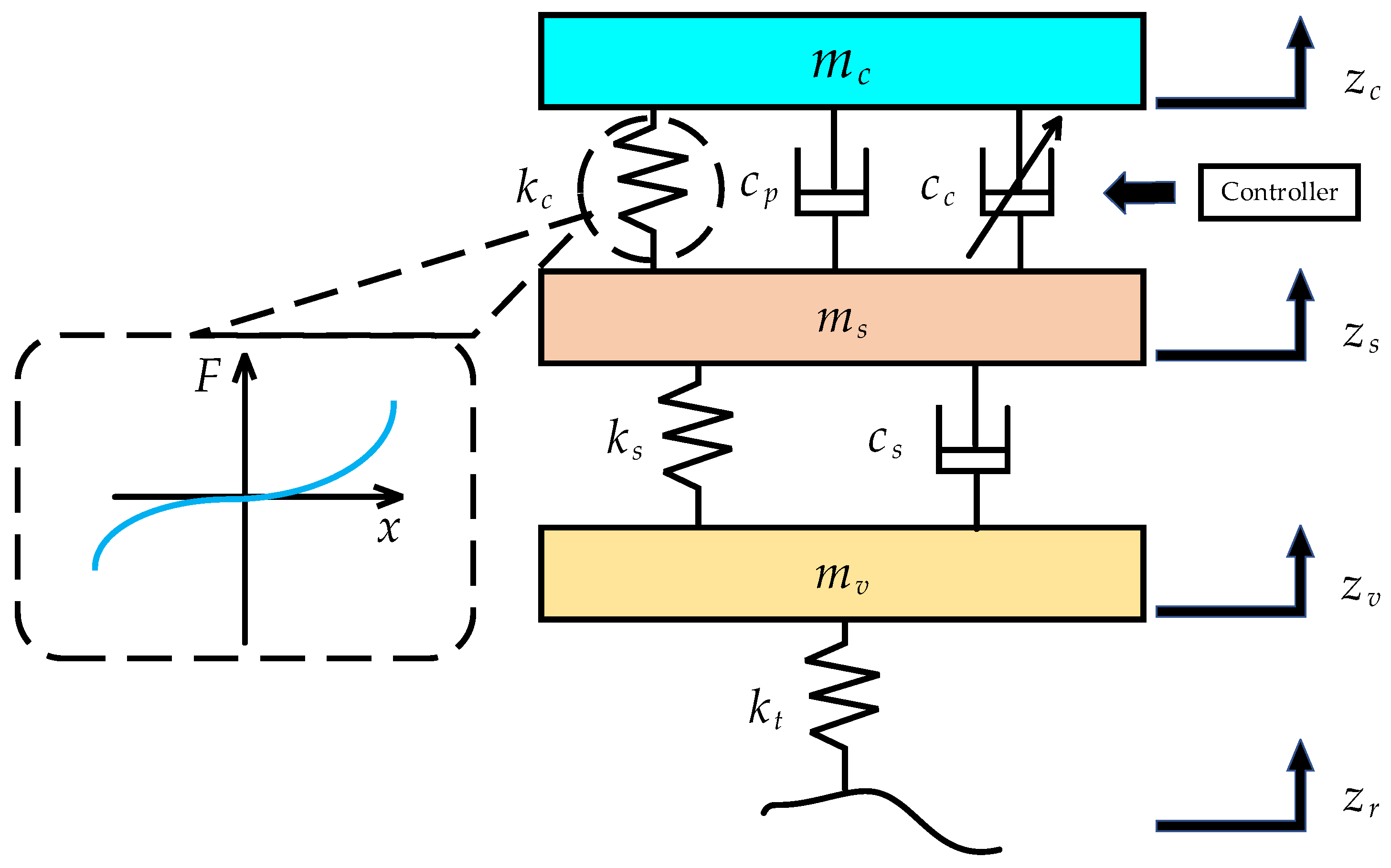
2.2. Quarter-Cab Car Suspension Model
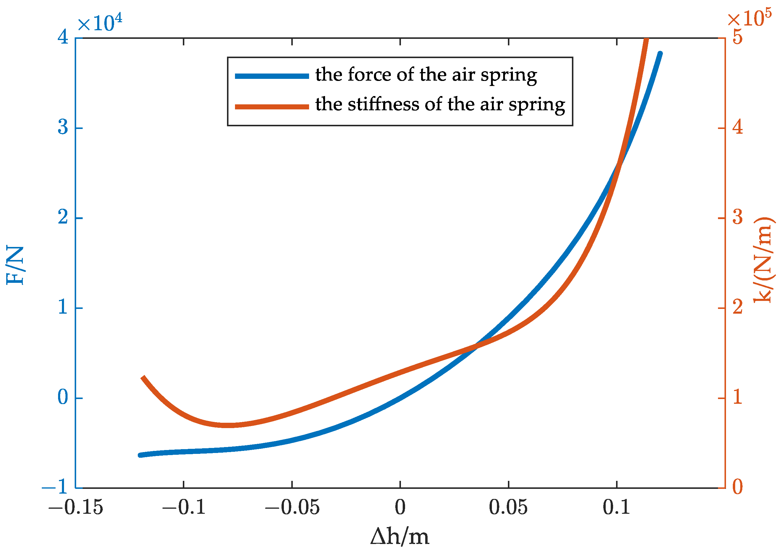
2.3. Mathematical Model of Air Spring
- The gas inside the airbag is regarded as ideal gas;
- The process of gas state change in the air spring is regarded as a quasi-static process;
- The air spring is not charged or deflated, but has an initial pressure and an initial volume .
2.4. Mathematical Model of Electromagnetic Damper
2.5. The Characteristic Experiment for the Electromagnetic Damper
3. Semi-Active Control Strategy for T-S Fuzzy Suspension Model
3.1. T-S Fuzzy Model of Suspension System
3.2. Luenberger State Observer Design
3.3. Robust H∞ Controller Design Based on State Observer
4. Numerical Simulations
4.1. Road Input Excitation Model
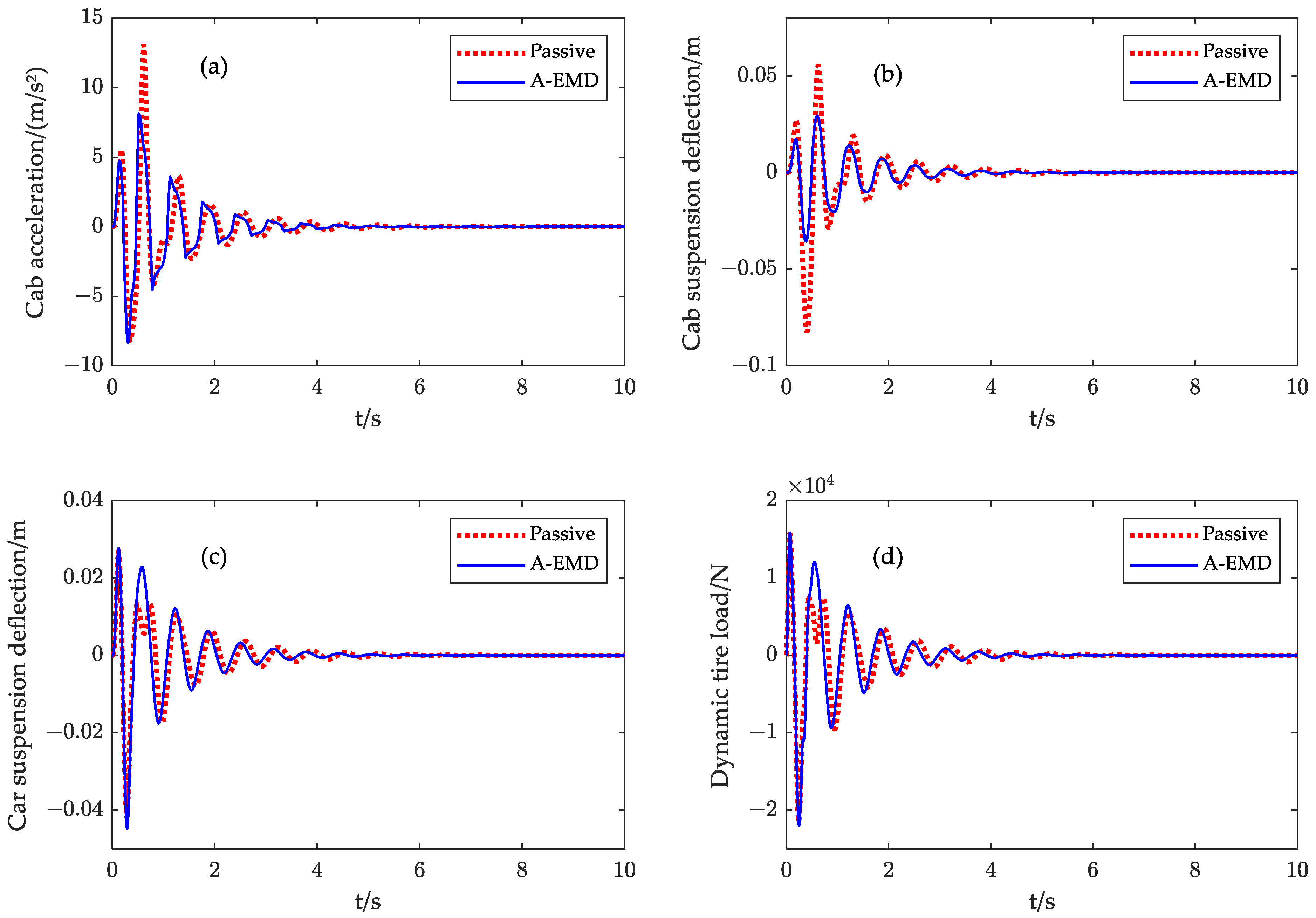
4.2. Performance Verification of the Novel Suspension −
5. Conclusions
Author Contributions
Funding
Data Availability Statement
Conflicts of Interest
Nomenclature
| the cab mass | the torque constant | ||
| the sprung mass | the voltage constant | ||
| the unsprung mass | the transmission ratio of the ball screw | ||
| the stiffness of the air spring | the internal resistance of the generator | ||
| the stiffness of the car suspension | the variable resistance | ||
| the tire stiffness | the maximum value of the variable resistance | ||
| the damping of the electromagnetic damper | the generator rotation speed | ||
| the fixed damping of cab suspension | the generated voltage | ||
| the damping of the car suspension | the current of generator external circuit | ||
| displacement of the cab mass | upper bound for the air spring stiffness | ||
| displacement of the sprung mass | upper bound for the air spring stiffness | ||
| displacement of the unsprung mass | , | the fuzzy membership functions | |
| the road displacement input | cab suspension limits travel | ||
| the force of the electromagnetic damper | car suspension limits travel | ||
| the initial pressure of the air spring | the performance index | ||
| the initial volume of the air spring | the cut-off frequency of road space | ||
| the initial height of the air spring | the standard spatial frequency | ||
| the atmospheric pressure | the height of the bump | ||
| the multivariate exponent | the length of the bump | ||
| the effective area of the air spring | the vehicle forward velocity | ||
| the air spring deformation | the state feedback gain matrices | ||
| the absolute pressure in the air spring | the observer matrices gain | ||
| the volume of the air spring |
References
- Tan, B.; Zhang, N.; Qi, H.; Zhang, B.; Wang, K.; Liu, J. Nonlinear dynamic analysis and experiments of a pressure self-regulating device for hydraulically interconnected suspension systems. Nonlinear Dyn. 2022, 111, 4173–4190. [Google Scholar] [CrossRef]
- Sim, K.; Lee, H.; Yoon, J.W.; Choi, C.; Hwang, S.-H. Effectiveness evaluation of hydro-pneumatic and semi-active cab suspension for the improvement of ride comfort of agricultural tractors. J. Terramech. 2017, 69, 23–32. [Google Scholar] [CrossRef]
- Tan, B.; Lin, X.; Zhang, B.; Zhang, N.; Qi, H.; Zheng, M. Nonlinear modeling and experimental characterization of hydraulically interconnected suspension with shim pack and gas-oil emulsion. Mech. Syst. Signal Process. 2023, 182, 109554–109571. [Google Scholar] [CrossRef]
- Soliman, A.M.A.; Kaldas, M.M.S. Semi-active suspension systems from research to mass-market–A review. J. Low Freq. Noise Vib. Act. Control. 2019, 40, 1005–1023. [Google Scholar] [CrossRef]
- Ma, R.; Do, C.M. Comfort-oriented Semi-active Matching Design with a Magneto-Rheological Air Suspension Mechanism. Iran. J. Sci. Technol. Trans. Mech. Eng. 2020, 45, 699–709. [Google Scholar] [CrossRef]
- Weber, F.; Spensberger, S.; Obholzer, F.; Distl, J.; Braun, C. Semi-Active Cable Damping to Compensate for Damping Losses Due to Reduced Cable Motion Close to Cable Anchor. Appl. Sci. 2022, 12, 1909–1926. [Google Scholar] [CrossRef]
- Yan, S.; Gu, Z.; Park, J.H.; Xie, X. Adaptive memory-event-triggered static output control of T–S fuzzy wind turbine systems. IEEE Trans. Fuzzy Syst. 2022, 30, 3894–3904. [Google Scholar] [CrossRef]
- Yan, S.; Gu, Z.; Park, J.H.; Xie, X. Sampled Memory-Event-Triggered Fuzzy Load Frequency Control for Wind Power Systems Subject to Outliers and Transmission Delays. IEEE Trans. Cybern. 2022, 1–11. [Google Scholar] [CrossRef]
- Yan, S.; Gu, Z.; Park, J.H.; Xie, X. Distributed-Delay-Dependent Stabilization for Networked Interval Type-2 Fuzzy Systems With Stochastic Delay and Actuator Saturation. IEEE Trans. Syst. Man Cybern. Syst. 2022, 1–11. [Google Scholar] [CrossRef]
- Güvenc, B.A.; Kural, E.; Keşli, B.; Gülbudak, K.; Güngor, S.; Kanbolat, A. Semi Active Suspension Control System Development for a Light Commercial Vehicle. IFAC Proc. Vol. 2006, 39, 391–396. [Google Scholar] [CrossRef]
- Qin, Y.; Zhao, F.; Wang, Z.; Gu, L.; Dong, M. Comprehensive Analysis for Influence of Controllable Damper Time Delay on Semi-Active Suspension Control Strategies. J. Vib. Acoust. 2017, 139, 031006. [Google Scholar] [CrossRef]
- Sun, S.; Tang, X.; Yang, J.; Ning, D.; Du, H.; Zhang, S.; Li, W. A New Generation of Magnetorheological Vehicle Suspension System With Tunable Stiffness and Damping Characteristics. IEEE Trans. Ind. Inform. 2019, 15, 4696–4708. [Google Scholar] [CrossRef]
- Yao, G.Z.; Yep, F.F.; Chen, G.; Li, W.H.; Yeo, S.H. MR damper and its application for semi-active control of vehicle suspension system. Mechatronics 2002, 12, 963–973. [Google Scholar] [CrossRef]
- Guo, D.L.; Hu, H.Y.; Yi, J.Q. Neural Network Control for a Semi-Active Vehicle Suspension with a Magnetorheological Damper. J. Vib. Control 2004, 10, 461–471. [Google Scholar] [CrossRef]
- Tang, X.; Du, H.; Sun, S.; Ning, D.; Xing, Z.; Li, W. Takagi–Sugeno Fuzzy Control for Semi-Active Vehicle Suspension With a Magnetorheological Damper and Experimental Validation. IEEE/ASME Trans. Mechatron. 2017, 22, 291–300. [Google Scholar] [CrossRef]
- Ning, D.; Du, H.; Sun, S.; Li, W.; Li, W. An Energy Saving Variable Damping Seat Suspension System With Regeneration Capability. IEEE Trans. Ind. Electron. 2018, 65, 8080–8091. [Google Scholar] [CrossRef]
- Wang, D. Study on Height Control of a Bus Equipped with HIS System and ECAS System. Master’s Thesis, Hunan University, Hunan, China, 2018. [Google Scholar]
- Marzbanrad, J.; Zahabi, N. H∞ active control of a vehicle suspension system exited by harmonic and random roads. Mech. Mech. Eng. 2017, 21, 171–180. [Google Scholar]
- Du, H.; Li, W.; Zhang, N. Integrated Seat and Suspension Control for a Quarter Car With Driver Model. IEEE Trans. Veh. Technol. 2012, 61, 3893–3908. [Google Scholar]
- Xia, X. Research on Vibration Control Algorithm of Seat Suspension Based on an Energy Saving Continually Controllable Electromagnetic Variable Damping System. Master’s Thesis, Hefei University of Technology, Anhui, China, 2020. [Google Scholar]
- Lo, J.C.; Lin, M.L. Observer-based robust H∞ control for fuzzy systems using two-step procedure. IEEE Trans. Fuzzy Syst. 2004, 12, 350–359. [Google Scholar] [CrossRef]
- Zhang, B.; Tan, C.A.; Dai, T. Ride comfort and energy dissipation of vehicle suspension system under non-stationary random road excitation. J. Sound Vib. 2021, 511, 116347–116364. [Google Scholar] [CrossRef]
- Du, H.; Lam, J.; Cheung, K.C.; Li, W.; Zhang, N. Direct voltage control of magnetorheological damper for vehicle suspensions. Smart Mater. Struct. 2013, 22, 105016–105029. [Google Scholar] [CrossRef]


| Symbol | Value |
|---|---|
| 794.5 kg | |
| 2364 kg | |
| 672 kg | |
| 492,400 N/m | |
| 1,728,000 N/m | |
| 2000 N·s/m | |
| 12,000 N·s/m |
| Symbol | Value |
|---|---|
| 0.7 MPa | |
| 9.5 L | |
| 0.252 m | |
| 0.1 MPa | |
| 1.381 |
| Symbol | Value |
|---|---|
| 0.454 Nm/A | |
| 0.454 Vs/rad | |
| 628.3 | |
| 7.625 Ω | |
| 120 Ω |
| Object | Passive | A-EMD |
|---|---|---|
| Cab acceleration (m/s2) | 2.5399 | 2.0207 |
| % | − | −20.44 |
| Cab suspension deflection (m) | 0.0153 | 0.0092 |
| % | − | −39.82 |
| Car suspension deflection (m) | 0.0106 | 0.0100 |
| % | − | −5.97 |
| Tire dynamic load (N) | 9097.8 | 8889.1 |
| % | − | −2.29 |
| Object | Passive | A-EMD |
|---|---|---|
| Cab acceleration (m/s2) | 21.3003 | 16.4479 |
| % | − | −22.78 |
| Cab suspension deflection (m) | 0.1382 | 0.0649 |
| % | − | −52.99 |
| Car suspension deflection (m) | 0.0690 | 0.0724 |
| % | − | 4.97 |
| Tire dynamic load (N) | 3736.9 | 3782.7 |
| % | − | 1.23 |
Disclaimer/Publisher’s Note: The statements, opinions and data contained in all publications are solely those of the individual author(s) and contributor(s) and not of MDPI and/or the editor(s). MDPI and/or the editor(s) disclaim responsibility for any injury to people or property resulting from any ideas, methods, instructions or products referred to in the content. |
© 2023 by the authors. Licensee MDPI, Basel, Switzerland. This article is an open access article distributed under the terms and conditions of the Creative Commons Attribution (CC BY) license (https://creativecommons.org/licenses/by/4.0/).
Share and Cite
Zhang, B.; Liu, M.; Wang, K.; Tan, B.; Deng, Y.; Qin, A.; Liu, J. Takagi–Sugeno Fuzzy Model-Based Control for Semi-Active Cab Suspension Equipped with an Electromagnetic Damper and an Air Spring. Machines 2023, 11, 226. https://doi.org/10.3390/machines11020226
Zhang B, Liu M, Wang K, Tan B, Deng Y, Qin A, Liu J. Takagi–Sugeno Fuzzy Model-Based Control for Semi-Active Cab Suspension Equipped with an Electromagnetic Damper and an Air Spring. Machines. 2023; 11(2):226. https://doi.org/10.3390/machines11020226
Chicago/Turabian StyleZhang, Bangji, Minyao Liu, Kunjun Wang, Bohuan Tan, Yuanwang Deng, An Qin, and Jingang Liu. 2023. "Takagi–Sugeno Fuzzy Model-Based Control for Semi-Active Cab Suspension Equipped with an Electromagnetic Damper and an Air Spring" Machines 11, no. 2: 226. https://doi.org/10.3390/machines11020226
APA StyleZhang, B., Liu, M., Wang, K., Tan, B., Deng, Y., Qin, A., & Liu, J. (2023). Takagi–Sugeno Fuzzy Model-Based Control for Semi-Active Cab Suspension Equipped with an Electromagnetic Damper and an Air Spring. Machines, 11(2), 226. https://doi.org/10.3390/machines11020226