Article

Experimental Study on Electro-Spark Additive/Subtractive Repair for Worn Cemented Carbide

1
School of Mechanical Engineering, Dalian Jiaotong University, Dalian 116028, China
2
School of Mechanical Engineering and Automation, Dalian Polytechnic University, Dalian 116034, China
*
Author to whom correspondence should be addressed.
Machines 2023, 11(3), 333; https://doi.org/10.3390/machines11030333
Submission received: 13 January 2023 / Revised: 22 February 2023 / Accepted: 26 February 2023 / Published: 28 February 2023
(This article belongs to the Section Material Processing Technology)

Abstract

:
Worn cemented carbide tool bits are often discarded because of the difficulty of their repair, resulting in a great deal of waste. Surface strengthening technology often extends the service life of worn tools. Electro-spark deposition (ESD) coating and matrix materials are metallurgically and closely bonded, and the approach has the characteristics of small heat input, a small heat-affected zone, and low repair cost, so it is suitable for strengthening the surface of cemented carbide tools. As the surface of cemented carbide tools is often not flat, which affects the uniformity of the deposited layer, the surface needs to be polished before ESD. Therefore, this paper proposed a method involving the electro-spark additive and subtractive repair of worn cemented carbide. Experiments involving the ultrasonic-assisted EDM grinding (UEDG) of cemented carbide were carried out. The effect of brass, 45 steel, and tungsten electrode materials on the removal rate, tool wear, and surface roughness were investigated. The results showed that the material removal rate of the tungsten electrode could reach 3.27 mm3/min, while the electrode loss was only 8.16%, and the average surface roughness was only 2.465 μm, which was better than the other two electrodes. Thus, the tungsten electrode exhibited a high material removal rate, low electrode loss, and good surface quality. The effects of the TiC, TiN, and TC4 electrodes on cemented carbide ESD were studied using optical 3D surface topography and other instruments, and the surface roughness, thickness, and hardness of the deposited layer were compared. The results showed that the surface roughness of the TC4 material reached 52.726 μm, which was better than that of the TiN and TiC materials. The thickness of the TiC deposition layer was 172.409 μm and the hardness value was 2231.9 HV; thus, the thickness and hardness of the TiC material’s sedimentary layer were better than those of the TiN and TC4 materials.

1. Introduction

Cemented carbide is widely used as a cutting tool due to its high corrosion resistance, wear resistance, heat resistance, excellent hardness, and strength [1,2,3]. However, when cemented carbide is worn, the machining accuracy and efficiency become poor [4]. At present, there are many technologies used for cemented carbide surface modification, which are mainly divided into mechanical, physical, and chemical methods according to their strengthening principles. The mechanical methods are mainly used to change the stress state and grain size of the surface layer of materials through various shot-peening techniques [5,6]. The physical methods mainly rely on heat energy, kinetic energy, and physical field to strengthen materials. Energetic beam remelting can significantly improve the wear resistance of components, with a fast processing time and high efficiency. It is suitable for strengthening components with simple structures; however, most high-energy beam remelting methods are limited by the size, shape, thickness, and other factors of the parts, and can cause a range of defects on the surface of the parts [7,8]. For this reason, they are unsuitable for the strengthening of parts with high requirements for surface integrity. The chemical methods cause chemical reactions on the surface of the cemented carbide. Appropriate technologies and treatment parameters must be selected based on the needs of different materials under specific working conditions. The strengthening effect of thermochemical treatment is affected by the composition of the surface layer, and the penetration process of elements is limited by solid solubility, lattice size, and other factors, meaning that the strengthening effect may be limited. However, if the matrix is uneven, this may also lead to an uneven strengthening layer [9,10,11]. The ESD coating and the matrix material are metallurgically and closely bonded, exhibiting the characteristics of small heat input, a small heat-affected zone, and low repair cost, and has gradually become a widely used process method in the field of surface strengthening. In addition, cemented carbide is expensive. Among the many methods available, electro-spark deposition is inexpensive and can be used to repair tools with a choice of deposition materials [12,13,14]; parts can be locally strengthened or repaired to make them reach or even exceed the original part quality and usage performance. With this in mind, an electro-spark additive/subtractive repair method that can effectively extend the life of cemented carbide tools and avoid uneven coating caused by uneven substrate surface has been developed.
The cutting of the surface of cemented carbide often forms a wear-damaged layer, so the use of the ESD method to repair carbide tools before subtractive treatment becomes necessary. Because cemented carbide has excellent hardness and strength, and electrical discharge machining (EDM) avoids the hardness and strength of the material and other attributes, ultrasonic assistance can improve the machining efficiency and surface quality, so ultrasonic-assisted EDM (UA-EDM) processing is considered the best choice for processing such materials. Scholars have conducted research in this area; Amir Abdullah et al. proved, through a large number of experiments, that the surface roughness of cemented carbide surfaces with UA-EDM is significantly better than traditional machining, and ultrasonic vibration can greatly improve the surface integrity of the cemented carbide (WC-Co10%) in EDM machining [15]. Kremer et al. showed that in EDM, the ultrasonic vibration of the electrode improves the machining process, and the large pressure changes in the gap lead to a more efficient discharge, thus improving the machining efficiency [16]. Hsue proposed an UA-EDM and rotary ultrasonic-assisted EDM (RU-EDM) spindle with an ultrasonic transducer for die sinking EDM and EDM milling processes. The experimental results revealed that RU-EDM is superior to conventional EDM in terms of the removal rate in both sinking and milling EDM [17]. In Zhang et al., the magnetic field-assisted electrical discharge machining (MF-EDM) of HVF-SiCp/Al was proposed to improve the sustainable machining performance. Based on the Taguchi method, a set of experiments were conducted and showed that pulse current is the major factor, and magnetic field-assisted technology significantly develops the surface integrity [18]. In order to prevent the failure of cemented carbide tools and prolong their service life, it is of great significance to use surface strengthening and damage repair for tools. Because electro-spark deposition has the characteristics of low overall cost, arbitrary selection of deposited materials, and firm combination of deposited coating and matrix, this type of technology is particularly suitable for the additive processing of cemented carbide tools. Zhang studied cemented carbide materials machined using ultrasonic vibration-assisted electrical discharge machining (UEDM) in a gas medium. Five types of cemented carbide material removal mechanisms, namely, melting or evaporation, spalling, oxidation, the force of high-pressure gas, and ultrasonic vibration affection, were discussed in detail [19]. Likewise, Wang studied the surface hardening of WC-8Co cemented carbide by integrating laser cladding and the ESD processes. Electro-spark coating was shown to possess a finer microstructure than laser coating [20]. Norbert Radek’s ESD process fully proved that the surface hardness of the material after deposition and the coefficient of friction of the coating is much higher than that of the undeposited material, and the corrosion resistance is also improved [21]. Burkov et al. studied the preparation of Ti-Al intermetallic coatings by ESD on Ti6Al4V alloys in a mixture of titanium and aluminum particles. It was found that with the increase in the aluminum concentration in the particle mixture, the corrosion resistance and oxidation resistance of the alloy improved. The wear rate of the coating decreased with the increase in the titanium concentration [22]. Wang et al. prepared a Mo coating on steel using an ESD process. The effects of the deposition parameters (deposition power, discharge frequency, and specific deposition time) on the roughness of the coating, thickness, and crack properties were investigated in detail; by comparing these properties, optimized deposition parameters were obtained. The results show that the Mo coating has better microhardness, wear resistance, and corrosion resistance than the substrate, which can significantly improve the service life of H13 steel [23].
ESD technology has the characteristics of low overall cost and arbitrary selection of deposited materials, which is one of the more important methods of additive manufacturing technology, but because cemented carbide materials often form a wear-damaged layer, resulting in the strong bond between the deposited coating and the matrix, this paper combines the advantages of UEDG and EDS technology to propose a repair method for Electro-spark Additive/Subtractive for cemented carbide. Previous researchers have made great progress in terms of ultrasonic-assisted EDM and ESD, but few have ever explored UEDG and the influencing factors in ESD. This paper studies the effect of the electro-spark additive and subtractive repair of cemented carbide. The EDM grinding workpiece makes it easier to combine the deposited material and the matrix material, so the workpiece is ground by selecting the optimal parameters obtained after UEDG, so as to carry out the ESD comparison experiment. The experimental results show that the EDM grinding and electro-spark deposition greatly improve the hardness, surface quality, and other properties of cemented carbide.

2. Electro-Spark Additive/Subtractive Repair Models

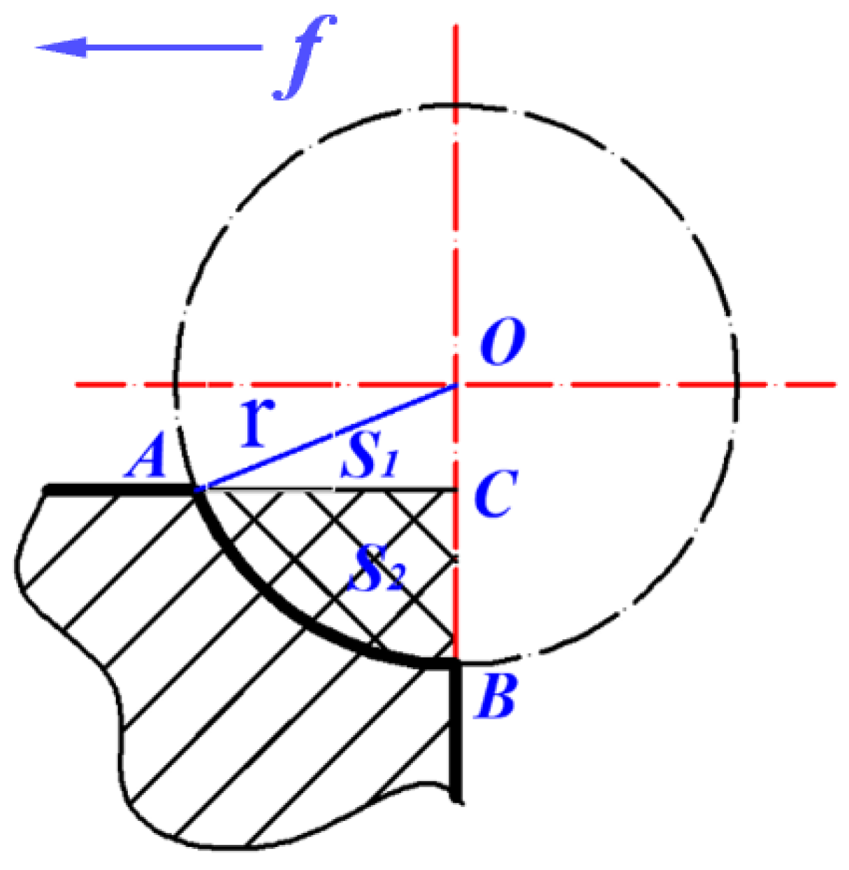
2.1. Ultrasonic-Assisted EDM Grinding Model

EDM grinding involves machining with the rotary motion of the electrode on the basis of conventional EDM. The electrode can not only be continuously fed under the control of the automatic feed control system, but can also be rotated around its axis, which is similar to traditional “grinding”. Figure 1 shows the schematic diagram of the EDM grinding process.
The advantage of EDM grinding is that the electrode continuously rotates during the machining, and a uniform loss occurs on the side of the electrode. The rotation of the electrode during the machining will drive the working fluid to flow at a high speed, and the debris will be washed away from the working fluid, improving the surface quality of the material and the next discharge environment.
UEDG changes the state of the discharge gap between the electrodes, making it easier to form the discharge channels; UEDG not only accelerates the movement speed of the electrodes, but also enhances the explosive force of the spark discharge and promotes the discharge of the electric erosion products. Due to the continuous rotation of the electrode during processing, the loss on the side of the electrode is uniform. Therefore, UEDG combines the advantages of traditional EDM, ultrasonic vibration, and rotating electrodes and is suitable for the processing of cemented carbide.

2.2. Electro-Spark Deposition Model

ESD is developed from traditional machining technology and is similar to the welding process. The process requirements for the workpiece are good electrical conductivity, and coatings containing various materials can be deposited onto the workpiece, as shown in Figure 2.
The power supply of the ESD process first needs to store more energy, and the two poles of the power supply are connected to the electrode and the cemented carbide, respectively. If the gap between the electrode and the cemented carbide reaches the discharge requirement, the energy stored in the power source will ionize the air to discharge, and the energy is released at high frequencies and produces sparks in the discharge channel.
The electro spark during deposition machining will only be generated in a small space, which will cause the cemented carbide to heat up around the discharge area, generating a high-temperature and high-pressure region. The temperature can reach 8000–25,000 °C. The high temperature can cause the electrode material to rapidly melt and deposit on the cemented carbide. The molten electrode material is combined with the cemented carbide to form an alloy. The surface of the cemented carbide after the ESD forms a highly wear-resistant and high-hardness deposit layer. The combination of the deposited layer and the cemented carbide belongs to the metallurgical bond and is very stable, which is beneficial to improve the machining performance of the cemented carbide and extend tool life [24].

3. Ultrasonic-Assisted EDM Grinding Experiments

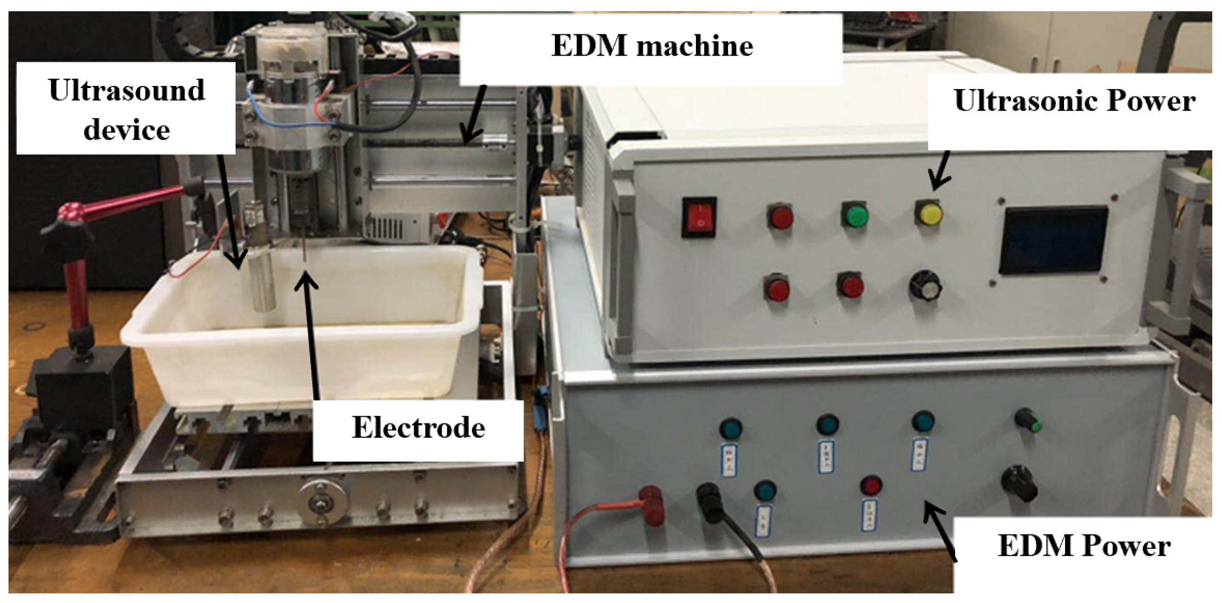
3.1. Experimental Setup of UEDG

The experimental setup is shown in Figure 3. It contains an EDM grinding machine and an ultrasonic generator. The EDM grinding machine is composed of an automatic feed control system and a power supply system. The tool is installed on the spindle. The spindle controls the rotation up and down movement of the electrode. The electrode is continuously moved closer to or away from the workpiece, and the size of the discharge gap is automatically controlled by a servo system. The ultrasonic generator is composed of ultrasonic power and an ultrasonic device, which can provide a vibration frequency of 20 kHz.
Since this experiment studies the influence of different materials’ electrodes on the material removal rate, electrode loss, and surface roughness of the machined surface of the UEDG process, it is necessary to control the factors that can affect the above findings including the maintenance voltage, pulse width, and peak current between the tool electrode and the workpiece, ensuring that the results of the study are only affected by the electrodes of different materials.
To be specific, because the cemented carbide insert is not easy to obtain and the cost is high, and the material properties of the cemented carbide block and the insert are exactly the same, the cemented carbide block is used instead of the insert for the investigation experiment. The working parameters are shown in Table 1.
The experiment uses an electronic scale to weigh the quality of the electrode before and after the experiment. The scale can change the unit of measurement. The experiment uses “gram” as the unit of measurement, and the measurement result is accurate to two decimal places.
The volume of the material to be measured and the surface roughness, etc., need to be measured by Alicona’s IFM G5 optical three-dimensional surface topography measuring instrument. From this machine, we can directly measure the value of the surface roughness, and the measurement of the length and volume of the etched part needs to be obtained by post-derivation calculation.
For the 45 steel, brass, and tungsten rod electrodes used in this experiment, the requirement for the electrode during EDM needs to have a higher melting point, better conductivity, and thermal conductivity. Table 2 gives the relevant physical parameter values for each material.

3.2. Experiment Results of UEDG

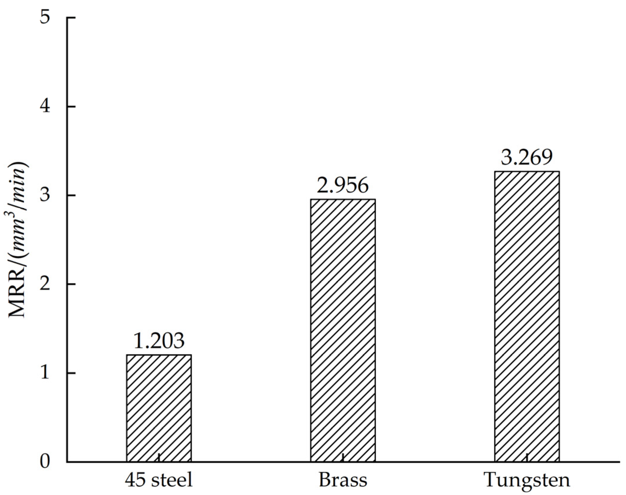
3.2.1. Effect of Different Electrode Materials on Material Removal Rate

The material removal rate (MRR) refers to the volume of the workpiece that is removed by the EDM in a unit of time. The MRR can directly reflect the speed of the electrode to remove the workpiece. The following is the calculation of the material removal rate:
v V = V V t
where v V is MRR, the unit is mm 3 / min ; V V is the removal volume of the workpiece, the unit is mm 3 ; t is the machining time, the unit is min.
Figure 4 shows the geometric model of EDM grinding. O is the center of the electrode and f is the feeding direction. The single section line part is the matrix of cemented carbide, and the double section line S2 is the part of cemented carbide that is etched during UEDG processing. S1 represents the area of the ΔAOC.
In the surface topography measuring instrument, the machining arc AB is fitted to a circle, the center of the circle is O, and the radius of the fitting circle is r. The OA and OB are connected, and OB intersects at point C on the surface of the original cemented carbide. The coordinates of the O, A, B, and C points can be read in the Cartesian coordinate system given by default in the instrument to calculate the area S2:
S 2 = a r c c o s   ( O C A C )   ×   π r 2 360 1 2   ×   A C   ×   O C
At this point, the area of the double section line area can be derived, and the thickness of the cemented carbide block can be obtained by multiplying by the thickness of the cemented carbide block. Table 3 shows the calculation of the data required for the determination and calculation of the erosion volume.
According to Table 3, the processing efficiency and material removal rate of different materials can be calculated. The feed rate v is calculated by Equation (3):
v = C B T p
where Tp is the processing time and CB is the feed length.
In this experiment, the EDM time was set to 5 min. The values of the machining results and MRR could be obtained by the surface topography measuring instrument, as shown in Figure 5.
In EDM, different electrical parameters lead to different processing efficiency, and the MRR of EDM is closely connected with the discharge energy per unit time [25]. However, in this experiment, the same electrode material with different electrical parameters will also lead to different processing efficiency. Figure 5 shows the comparison of the MRR for different electrode materials. It can be concluded that three different materials have a great influence on the material removal rate and machining efficiency. According to the data obtained by the experiments, the machining efficiency of the tungsten electrode is the highest and the 45 steel is the lowest, and the material absorption rate of the brass and tungsten electrodes is not much different. In addition, the MRR increases with the increase in the feed rate.
This is because the tungsten electrode is doped with some rare-earth oxides with low electronic work function, for example, cerium oxide, lanthanum oxide, zirconia, yttrium oxide and other rare earth oxides. The tungsten element electron escape work is 4.54 eV, due to the doping of rare earth oxides, so that the electron escape work of the tungsten electrode is lower than 4.54 eV—far lower than the other two materials, according to the Richardson–Dushman equation:
j e = A D ¯ T 2 e ϕ M / k T
where j e is the thermal emission current density, A is emission constant, D ¯ is electron transmission coefficient, k is Boltzmann’s constant, T is the absolute temperature, and ϕ M is the escape work.
This not only increases the recrystallisation temperature, but also activates electron emission, resulting in a discharge energy density greater than the other two materials and a large amount of energy used to remove the volume of carbide. The total energy used to remove the tungsten carbide is greater than the other two materials. In addition, due to the large electrode wear of brass and 45 steel, more discharge debris is produced. This discharge debris contains a large number of impurity particles that cause the discharge to become unstable, which can easily lead to harmful arcs, thus increasing the material removal rate and machining efficiency of the tungsten electrode material for the cemented carbide.

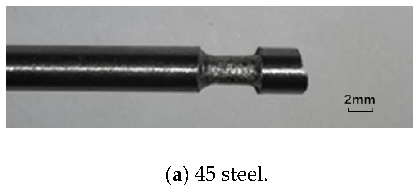
3.2.2. Effect of Different Electrode Materials on Electrode Wear

In UEDG, as the experiment progresses, the effect of the discharge energy causes wear in the mass, volume, and length of the electrode material. This loss directly affects the shape of the electrode, the amount of discharge energy and the state of discharge, which in turn affects the machining efficiency of EDM, the quality of the surface, and the machining accuracy [26]. Therefore, understanding the wear characteristics of electrode materials is the key to controlling electrode wear in EDM.
Figure 6 shows the loss of the three different electrodes under EDM grinding for 5 min. The electrode loss is evenly distributed on the side of the electrodes in EDM grinding.
The relative electrode wear is calculated as follows:
  θ = ( v E v M )   ×   100 %
where θ is the relative loss of the electrode; v E is the removal speed of the electrode, the unit is g/min; and v M is the removal speed of the workpiece, the unit is g/min, the value of which can be calculated by MRR and cemented carbide density as:
v M = v V   ×   ρ
The absolute loss rate of the electrode mass can be calculated by:
v E = M E / t
where M E is the absolute electrode wear, the unit is g; and t is the machining time, the unit is min.
It can be seen from Table 4 that the absolute loss of the tungsten electrode is much smaller than that of the other two materials, and the electrode of the 45 steel material is slightly smaller than the brass electrode.
The characteristics of electrode materials in EDM are important factors affecting electrode wear, and electrode materials with high electrical and high thermal conductivity are not easily corroded. According to the Wiedemann–Franz law, there is a positive correlation between electrical and thermal conductivity. In terms of the physical characteristics of the electrode, because tungsten electrodes have a strong ability to conduct current, they are more resistant to electrical corrosion and the amount of wear is small. Figure 7 shows the relationship between the relative tool wear and conductivity and thermal conductivity of different materials, and the relative tool wear increases as the conductivity and thermal conductivity decrease. In addition, the tungsten electrode has the lowest relative tool wear due to its high melting point. Because the corrosion resistance is strong, it is suitable for EDM machining. By comparing the thermal conductivity of the three electrode materials, it is found that the conductivity of the tungsten electrode is greater than the brass electrode and that of the brass electrode is greater than the 45 steel electrode. The better the thermal conductivity, the more heat diffuses to the surrounding environment, so less local heat is used to melt the electrode material; this is why the tool wear rate of the tungsten electrode is lower than that of the brass and 45 steel electrodes. In addition, the presence of carbon in the 45 steel increases the formation of a carbon black film on the surface of the positive workpiece, which hinders the removal of workpiece material, but increases the loss of the tool electrode. Thus, the 45 steel has the largest electrode loss and weakest corrosion resistance, and is therefore not suitable for EDM machining.

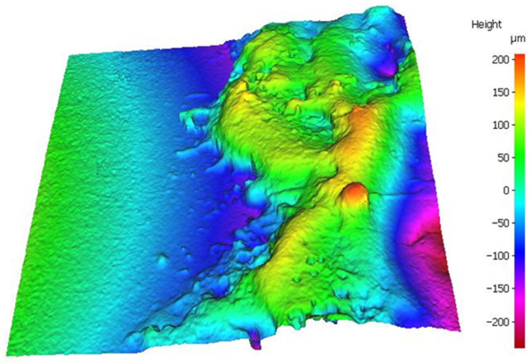
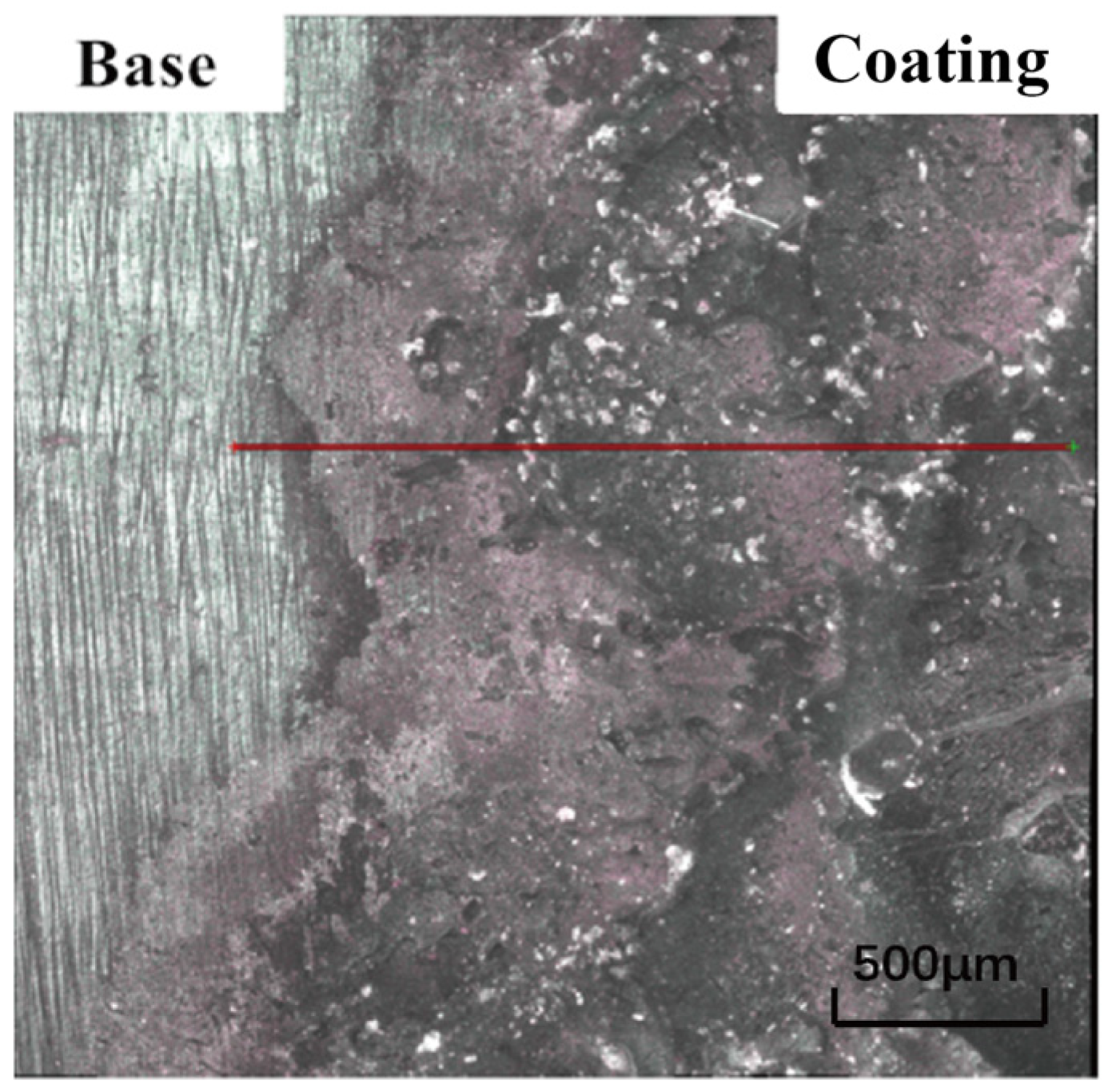
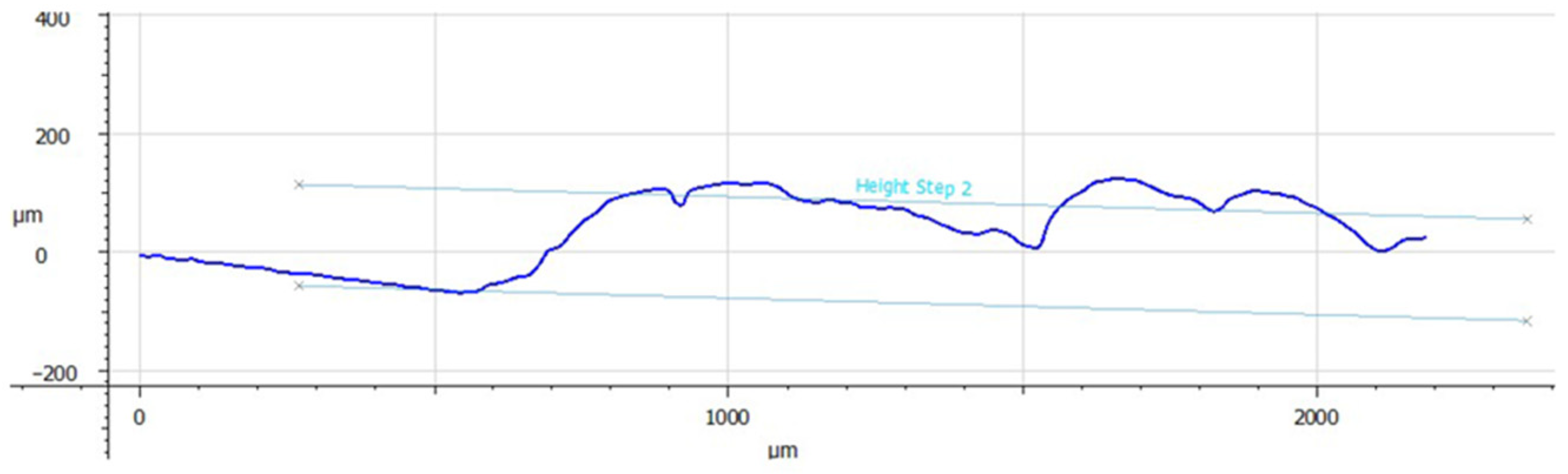
3.2.3. Distribution of Electrode Materials in the Molten Pool

The surface roughness of the different electrode materials was studied. The machining depth selected to be 2 mm. In Figure 8, the red line is the measurement position. In order to ensure the accuracy of the measurement results, three different locations on the red line are selected for measurement, and finally the average value is calculated. The measured surface roughness morphologies are shown in Figure 8a.
Figure 8b shows the surface roughness curve after machining with different electrodes. From Figure 5, we know that the material removal rate of the tungsten electrode is greater than that of the brass electrode and greater than that of the 45 steel electrode. Compared to the other two surfaces, the cemented carbide machined by tungsten shows a better surface roughness compared with the other two surfaces. This is because the tungsten electrode has good electrical and thermal conductivity. In this experiment, positive polarity processing is used to process the interpolar discharge because the tungsten electrode has a low electronic work function, it is easier for electrons to escape, the discharge energy density is relatively high, and the area eroded by the discharge is relatively large and flat. In addition, in the process of discharge removal, the tungsten electrode can easily form a bulge at the edge of the molten pool. Due to the greater electric field strength and discharge required to remove the bulge, the surface roughness of the tungsten electrode is relatively better. Brass electrodes have the worst surface roughness due to low material removal. As the material removal rate is the lowest for 45 steel, the molten pool formed during processing is the smallest, so the surface roughness is lower than that of the brass electrodes. Brass and 45 steel electrodes have a large relative loss and poor machining stability; moreover, arcing phenomena easily occur during the machining that worsen the value of the surface roughness. Figure 9 shows the average values of three different electrodes. The surface roughness of tungsten is 2.465 and the average value of the brass is 3.888.
Based on the above experimental results, compared to brass and 45 steel electrodes, UEDG processing with tungsten electrodes is more stable and has better surface roughness. Therefore, we chose tungsten electrodes and optimal electrical parameters for the removal of the workpiece surface for conducting comparative ESD.

4. Comparative Experiment of Electro-Spark Deposition Machining

4.1. Experimental Setup of ESD

The effects of different electrode materials on the deposition layer were studied. The electro-spark deposition machine used in this experiment is an electro-spark surface repair. The depositional experiment of cemented carbide coatings can be carried out using the surface strengthening function of this machine. Before the experiment, the deposited workpiece should be fixed with a vice, and the negative pole of the power supply should be connected to the vice. The positive pole of the power supply is connected to the handle. The ultrasonic device is connected to the workpiece, and the tool electrodes are connected to the spindle. The power of the machine and the argon valve are turned on.
The electrode materials were TiC, TiN, and TC4, the discharge voltage was 50 V, and the deposition time was 5 min. The experiment parameters are shown in Table 5.
Table 6 shows the values of the relevant physical parameters for each of the three electrode materials used in this experiment.

4.2. Experimental Results

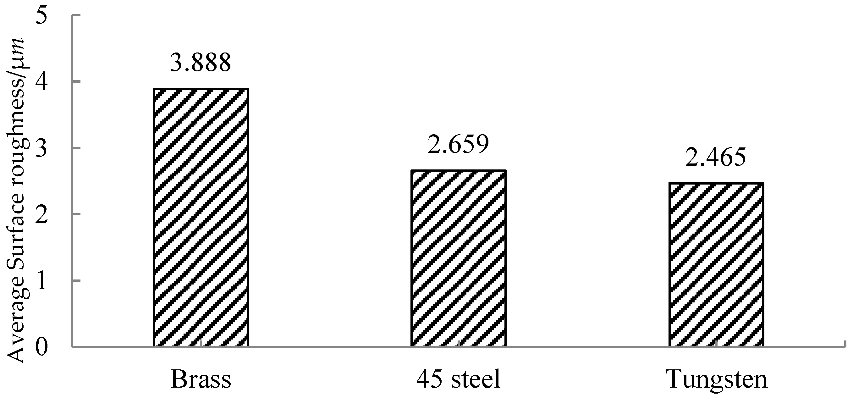
4.2.1. Effect of Different Electrode Materials on the Surface Roughness of the Deposited Layer

The cemented carbide that needs to be deposited is first processed in EDM. This not only meets the purpose of the additive and subtractive repair of the cemented carbide, but also removes impurities and oxide layers on the surface of the cemented carbide. ESD was carried out within the specified time, and measured using the optical three-dimensional surface topography measuring instrument shown in Figure 10. For each set of measurements, three areas of the same size ( 500   μ m   ×   500   μ m ) were selected and then the average values were calculated, as shown in Table 6.
In order to visually observe the influence of different electrodes on the surface roughness of the deposited layer, the experimental data are presented as a line figure. The arithmetic mean of multiple groups of experimental data was taken as the reference point, and the difference between the multi-group experimental data and the arithmetic mean was displayed in the form of error bars. As shown in Figure 11, the average value of TC4 is the smallest, indicating that the surface quality of the workpiece machined by the TC4 electrode is the best. The surface quality of the workpiece machined by TiC is 153.943, which is the worst among the three electrodes.
If we ignore errors due to operator proficiency, the main reason that the surface of the ESD layer is not the same and is not smooth is that when the deposition electrode is melted and combined with the substrate of the workpiece, the combination of the different electrodes and the substrate is different, and the generated substances are not the same. Porosity inevitably occurs between molecules, and the macroscopic appearance is the occurrence of pores or shallow pits on the surface, which affects the surface roughness value.
From the results obtained above, the surface quality of the TC4 material is the best under the same conditions; TiN is second; and TiC is the poorest. It can be said that the combination of TC4, TiN, and TiC materials and cemented carbides varies from good to bad. Comparing the resistivity, we find that, under the same conditions, the surface roughness of the deposited layer will decrease and the surface will be smooth as the resistivity of the material decreases. A black area appears on the surface of the deposited layer, which is caused by the overheating of the electrode material during the spark discharge.

4.2.2. Effect of Different Electrode Materials on the Thickness of the Deposited Layer

Since the thickness of the deposited layer is to be detected, the area of the deposited layer and the deposition time must be strictly controlled while minimizing the influence of the operator on the experiment. After the end of the experiment, the deposition thickness is directly measured without any treatment of the surface of the deposited layer. Considering the surface roughness of the deposited layer and determining the thickness of the deposit, the average value is taken after three measurements.
An optical three-dimensional surface topography measuring instrument is used to measure the deposited layer of each material at three different positions. In Figure 12, the red line is the measurement position. The height difference between the surface of the deposited layer and the original surface was measured as shown in Figure 13.
Figure 14 shows the measurement results of the deposited layer thickness. The TiC material has the largest deposit thickness, the TiN material is the second, and the TC4 material is the thinnest. The coating thickness of the ESD process is related to the electrode material. Therefore, it is necessary to select a better ductile electrode material to deposit the coating. This is because, as the thickness of the deposited layer increases, the ductile material deposit layer is more easily released, which is more suitable for ESD than the less ductile electrode material. Therefore, the ductility of TiC material is slightly higher than that of the TiN and TiC materials.

4.2.3. Effect of Different Electrode Materials on the Hardness of the Deposited Layer

Before starting to measure the hardness, it is necessary to use sandpaper polishing paste to polish the surface of the deposited layer. If the surface of the deposited layer is not polished, the image will not be clearly displayed or the measurement results will be inaccurate. In order to avoid errors in the results, three different points were chosen for measurement, and then the average values were calculated. The results of the hardness measurement of the deposited layer are shown in Figure 15.
As shown in Figure 15, we found that under the same experimental conditions, the hardness of TiC is the highest, TC4 is the second, and TiN is the lowest. This is mainly due to the fact that TiC has the highest hardness at roughly 3400 HV. The hardness value of TiC dropped from 3400 HV to 2231.9 HV, mainly because in the process of ESD, some TiC and workpiece materials underwent material transformation when the TiC electrode changed from melting to resolidification, which reduced its hardness value. In addition, the surface hardness strengthening effect of the deposited layer is closely related to the carbon content in this layer. The carbon in the electrode can compensate for the loss of carbon during the discharge process, and it can also be said that the higher the carbon content, the higher the surface hardness [27]. TiC materials have the highest carbon content, so the hardness of the deposited layer is the highest. The TC4 material also contains carbon and Ti is formed during deposition, so the hardness is also high. Therefore, the hardness of the deposited layers of TiC and TC4 materials is higher than for TiN.

5. Conclusions

This paper focuses on the EDM additive and subtractive repair of worn cemented carbide. The comparison experiments of different electrode materials on the UEDG of cemented carbide and the comparison experiments of different electrode materials on ESD are summarized. The conclusions are as follows:
(1)
In the experiment studying the influence of different electrode materials on ultrasonic-assisted EDM grinding, the material removal rate of the tungsten electrode reached 3.27 mm3/min. The tungsten electrode showed the highest material removal rate and machining efficiency, lowest electrode loss, and best surface quality. The material removal rate of the brass electrode was 2.96 mm3/min, which was higher than that of a 45 steel electrode of 1.2 mm3/min, and 45 steel electrodes have better surface quality than brass.
(2)
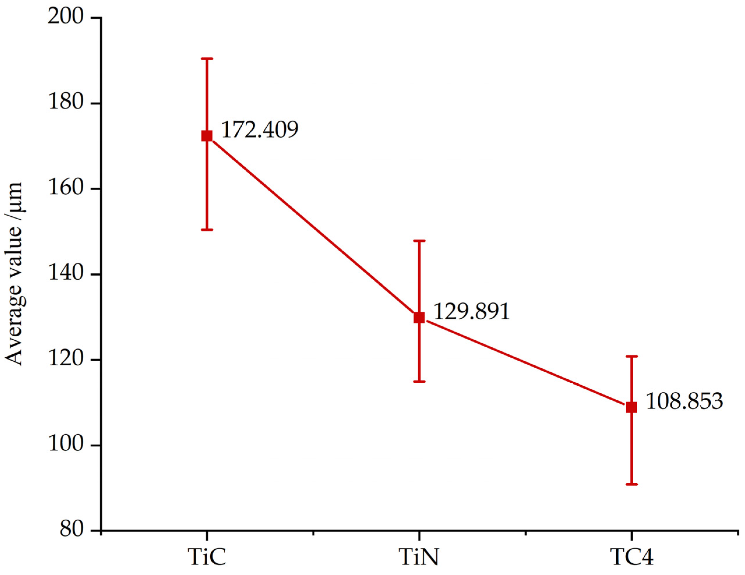
In the comparative experiment of ESD on cemented carbide, the effects of TiC, TiN, and TC4, which are commonly used as cemented carbide coatings, on the deposition effect were investigated. Under the same deposition conditions, the surface roughness of the TC4 material is better than that of the TiN and TiC materials. The hardness of the deposition layer of TiC is the greatest among the three materials, and the hardness value reaches 2231.9 HV, which is higher than the hardness value of 2104.5 HV and 2199.8 HV for TiN and TC4, respectively; thus, the thickness and hardness of the TiC material deposition layer are better than for TiN and TC4.

6. Innovation and Prospects for Future Research

In the UEDG process on cemented carbide, since the volume of the workpiece to be etched cannot be directly measured by the three-dimensional surface topography measuring instrument, the method of measuring the coordinates and then calculating the volume of the etching was indirectly used. The method is not limited to the trend of the research data, and the experimental data of the UEDG process and the ESD-cemented carbide are quantified.
Although this experiment can be used for improving the effect of the EDM additive and subtractive repairing of worn cemented carbide inserts in actual manufacturing, several shortcomings were identified in the experiment, as follows:
(1)
In the UEDG experiment, the oxide layer appears on the surface of the cemented carbide after processing. If the oxide layer is not treated, it will affect the later deposition processing effect. If methods and techniques for reducing or eliminating oxide layers can be developed, this will effectively improve the efficiency of EDM addition and reduction.
(2)
In the ESD experiment, the tester’s operation level is required to be high, and any carelessness on the part of the operator may adversely affect the spark deposition effect. Therefore, if the ESD process can achieve automatic control, the processing effect and efficiency will be significantly improved.

Author Contributions

Y.L. and J.Q. conceived the idea of this work; J.Q. and X.C. conducted the simulation; data curation, W.Z.; original draft preparation, J.Q.; review and editing, Y.L. and S.Z. All authors have read and agreed to the published version of the manuscript.

Funding

The financial support from the General Program of Natural Science Foundation of Liaoning Province under grant no. 2022-MS-340, Liaoning BaiQianWan Talents Program under grant no. 2021921025, and the Natural Science Basic Research Project of the Education Department of Liaoning Province under grant no. JDL2020009 is acknowledged.

Data Availability Statement

The data used to support the findings of this study are available from the corresponding author upon request.

Conflicts of Interest

The authors declare that there is no conflict of interest regarding the publication of this paper.

References

  1. Feng, H.; Xiang, D.; Wu, B.; Zhao, B. Ultrasonic vibration-assisted grinding of blind holes and internal threads in cemented carbides. Int. J. Adv. Manuf. Technol. 2019, 104, 1357–1367. [Google Scholar] [CrossRef]
  2. Holubets, V.M.; Pashechko, M.I.; Borc, J.; Tisov, O.V.; Shpuliar, Y.S. Wear resistance of electrospark-deposited coatings in dry sliding friction conditions. Powder Metall. Met. Ceram. 2021, 60, 90–96. [Google Scholar] [CrossRef]
  3. Enrique, P.D.; Peterkin, S.; Zhou, N.Y. Parametric Study of Automated Electrospark Deposition for Ni-Based Superalloys. Weld. J. 2021, 100, 239S–248S. [Google Scholar] [CrossRef]
  4. Li, Y.; Deng, J.; Chai, Y.; Fan, W. Surface textures on cemented carbide cutting tools by micro EDM assisted with high-frequency vibration. Int. J. Adv. Manuf. Technol. 2016, 82, 2157–2165. [Google Scholar] [CrossRef]
  5. Qutaba, S.; Asmelash, M.; Saptaji, K.; Azhari, A. A review on peening processes and its effect on surfaces. Int. J. Adv. Manuf. Technol. 2022, 120, 4233–4270. [Google Scholar] [CrossRef]
  6. Bagherifard, S. Enhancing the structural performance of lightweight metals by shot peening. Adv. Eng. Mater. 2019, 21, 1801140. [Google Scholar] [CrossRef]
  7. Dong, C.; Wu, A.M.; Hao, S.Z.; Zou, J.; Liu, Z.; Zhong, P.; Zhang, A.; Xu, T.; Chen, J.; Xu, J.; et al. Surface treatment by high current pulsed electron beam. Surf. Coat. Technol. 2003, 163, 620–624. [Google Scholar] [CrossRef]
  8. Brown, M.S.; Arnold, C.B. Fundamentals of Laser-Material Interaction and Application to Multiscale Surface Modification; Laser Precision Microfabrication: Berlin/Heidelberg, Germany; Springer: Berlin/Heidelberg, Germany, 2010; pp. 91–120. [Google Scholar]
  9. Rajan, T.S.; Sharma, C.P.; Sharma, A.K. Heat Treatment: Principles and Techniques; PHI Learning Pvt. Ltd.: New Delhi, India, 2011. [Google Scholar]
  10. Mittemeijer, E.J.; Somers, M.A. (Eds.) Thermochemical Surface Engineering of Steels; Woodhead Publishing: Cambridge, UK, 2014. [Google Scholar]
  11. Czerwinski, F. (Ed.) Heat Treatment: Conventional and Novel Applications; BoD–Books on Demand: Norderstedt, Germany, 2012. [Google Scholar]
  12. Sychev, A.P.; Kolesnikov, I.V.; Sycheva, M.A. Extending the life of frictional components in freight cars by hybrid electrospark deposition. Russ. Eng. Res. 2022, 42, 49–52. [Google Scholar] [CrossRef]
  13. Tarelnyk, V.B.; Gaponova, O.P.; Myslyvchenko, O.M.; Sarzhanov, B.O. Electrospark deposition of multilayer coatings. Powder Metall. Met. Ceram. 2020, 59, 76–88. [Google Scholar] [CrossRef]
  14. Senin, P.V.; Velichko, S.A.; Martynov, A.V.; Martynova, E.G. Increasing the wear resistance of forged tools by electrospark deposition. Russ. Eng. Res. 2020, 40, 427–430. [Google Scholar] [CrossRef]
  15. Abdullah, A.; Shabgard, M.R.; Ivanov, A.; Shervanyi-Tabar, M.T. Effect of Ultrasonic-assisted EDM on the Surface Integrity of Cemented Tungsten Carbide (WC-Co). Int. J. Adv. Manuf. Technol. 2009, 49, 268–280. [Google Scholar] [CrossRef]
  16. Kunieda, M.; Nishiwaki, X. Observation of Arc Column Movement during Mono-pulse Discharge in EDM. Ann. CIRP 1992, 14, 150–157. [Google Scholar]
  17. Hsue, A.W.J.; Hab, T.J.; Lin, T.M. Pulse efficiency and gap status of rotary ultrasonic assisted electrical discharge machining and EDM milling. Procedia CIRP 2018, 68, 783–788. [Google Scholar] [CrossRef]
  18. Zhang, Z.; Zhang, Y.; Lin, L.; Wu, J.; Yu, H.; Pan, X.; Li, G.; Wu, J.; Xue, T. Study on productivity and aerosol emissions of magnetic field-assisted EDM process of SiCp/Al composite with high volume fractions. J. Clean. Prod. 2021, 292, 126018. [Google Scholar] [CrossRef]
  19. Xu, M.G.; Zhang, J.H.; Li, Y.; Zhang, Q.H.; Ren, S.F. Material removal mechanisms of cemented carbides machined by ultrasonic vibration assisted EDM in gas medium. J. Mater. Process. Technol. 2009, 209, 1742–1746. [Google Scholar] [CrossRef]
  20. Wang, J.; Meng, H.; Yu, H.; Fan, Z.; Sun, D. Surface hardening of Fe-based alloy powders by Nd:YAG laser cladding followed by electrospark deposition with WC-Co cemented carbide. Rare Met. 2010, 29, 380–384. [Google Scholar] [CrossRef]
  21. Radek, N.; Bartkowiak, K. Laser Treatment of Cu-Mo Electro-spark Deposited Coatings. Phys. Procedia 2011, 32, 499–505. [Google Scholar] [CrossRef] [Green Version]
  22. Burkov, A.A.; Chigrin, P.G. Synthesis of Ti-Al intermetallic coatings via electrospark deposition in a mixture of Ti and Al granules technique. Surf. Coat. Technol. 2020, 387, 125550. [Google Scholar] [CrossRef]
  23. Wang, W.; Du, M.; Zhang, X.; Luan, C.; Tian, Y. Preparation and Properties of Mo Coating on H13 Steel by Electro Spark Deposition Process. Materials 2021, 14, 3700. [Google Scholar] [CrossRef]
  24. Guo, X. Research on Process of Electro-spark Surface Deposition. New Technol. New Process. 2012, 9, 96–98. (In Chinese) [Google Scholar]
  25. Guo, H.; Cao, M. Method and Experimental Study of EDM in Reducing Electrode Wear. Mod. Manuf. Eng. 2014, 9, 85–89. (In Chinese) [Google Scholar]
  26. Konyashin, I.Y. PVD/CVD technology for coating cemented carbides. Surf. Coat. Technol. 1995, 71, 277–283. [Google Scholar] [CrossRef]
  27. Gao, D.; Shen, D. Research on Improve the Hardness of Electro-spark Strength Layer. Mater. Mech. Eng. 2000, 24, 16–18. (In Chinese) [Google Scholar]
Figure 1. Diagram of EDM grinding machining.
Machines 11 00333 g001
Figure 2. Diagram of ESD machining.
Machines 11 00333 g002
Figure 3. Ultrasonic-assisted EDM grinding machine.
Machines 11 00333 g003
Figure 4. Geometric model of EDM grinding.
Machines 11 00333 g004
Figure 5. Comparison of feed rate and MRR for different electrode materials.
Machines 11 00333 g005
Figure 6. Absolute wear of three different electrode materials.
Machines 11 00333 g006aMachines 11 00333 g006b
Figure 7. Relative mass loss of three electrodes.
Machines 11 00333 g007
Figure 8. (a). Cemented carbide surface after machining (from left to right: brass, 45 steel, tungsten). (b). Surface roughness curve after machining with different electrodes (from left to right: brass, 45 steel, tungsten).
Machines 11 00333 g008aMachines 11 00333 g008b
Figure 9. Comparison of surface roughness of the three materials.
Machines 11 00333 g009
Figure 10. Three-dimensional surface topography of ESD.
Machines 11 00333 g010
Figure 11. Comparison of resistivity and deposition surface roughness of different materials.
Machines 11 00333 g011
Figure 12. Surface profile measurement.
Machines 11 00333 g012
Figure 13. Surface profile measurement (average height is measured in the section).
Machines 11 00333 g013
Figure 14. Deposition thickness measurement results.
Machines 11 00333 g014
Figure 15. Deposition layer hardness measurement results.
Machines 11 00333 g015
Table 1. Experimental parameters of EDM grinding.
ParametersDescriptions
Maintenance voltage70 V
Peak current10 A
Pulse width20 μs
Working fluidDeionized water
Tool electrode material45 steel, brass, tungsten
Tool sizeL = 70 mm, ∅ = 4 mm
Workpiece materialCemented carbide
Workpiece size40 mm × 41 mm × 5 mm
PolarityPositive
Machining depth2 mm
Ultrasonic frequency20 kHz
Measuring instrumentIFM G5 surface topography measuring instrument
Table 2. Physical parameters of electrodes of different materials.
Electrode MaterialMelting Point/°CConductivity/(S/m)Thermal Conductivity/(W/(m·K)Density/(g/cm3)
Brass H8096714.49108.98.7
45 steel14955.0050.27.85
Tungsten339018.6017419.35
Table 3. Calculation of the data required for the determination and calculation of the erosion volume.
Electrode Materialr/mmCoordinate Valueθ/°Area/mm2
Point OPoint APoint BPoint CS3S1S2
45 steel1.98358.769,
23.543
57.053,
22.549
58.769,
21.560
58.769,
22.549
59.9172.0560.8531.203
Brass H801.96896.189,
16.516
94.221,
16.472
96.189,
14.548
96.189,
16.472
88.7192.9990.0432.956
Tungsten2.0552.769,
58.182
0.715,
58.159
2.769,
56.127
2.769,
58.159
89.3593.2930.0243.269
Table 4. Comparison of relative mass loss of electrodes.
Electrode MaterialProcessing Time
t/min
Absolute Loss
ME/g
Absolute Loss Rate
vE/(g/min)
Workpiece Removal Speed
vM/(g/min)
Brass H8050.300.0600.018
45 steel50.210.0420.044
Tungsten50.020.0040.049
Table 5. ESD comparative experiment conditions.
ParametersDescription
Discharge voltage50 V
Deposition frequency400 Hz
Pulse width percentage20%
Deposition time5 min
Protective gasArgon
PolarityNegative
Electrode materialTiC, TiN, TC4(Ti-6Al-4V)
Electrode sizeL = 100 mm, ∅ = 2.5 mm
Coating area5 mm × 5 mm
Table 6. Physical parameters of electrodes of different materials.
Electrode MaterialMelting Point/°CResistivity/(μΩ/m)Thermal Conductivity/(W/(m·K))Density/(g/cm3)Hardness/HV1.0
TiC31605021.004.943400
TiN29502519.205.242300
TC416781.67.964.51310
Disclaimer/Publisher’s Note: The statements, opinions and data contained in all publications are solely those of the individual author(s) and contributor(s) and not of MDPI and/or the editor(s). MDPI and/or the editor(s) disclaim responsibility for any injury to people or property resulting from any ideas, methods, instructions or products referred to in the content.

