Article

Equivalent Dynamic Modeling for the Relative Rotation of Bolted Joint Interface Using Valanis Model of Hysteresis

College of Civil Engineering, Nanjing Forestry University, Nanjing 210037, China
*
Author to whom correspondence should be addressed.
Machines 2023, 11(3), 342; https://doi.org/10.3390/machines11030342
Submission received: 9 January 2023 / Revised: 19 February 2023 / Accepted: 22 February 2023 / Published: 2 March 2023
(This article belongs to the Section Machines Testing and Maintenance)

Abstract

:
Dynamic modeling of the joint interface is critical to the performance analysis of bolt-jointed structures. In this work, an equivalent modeling method was presented for modeling the relative rotation of the joint interface in bolt-jointed beam structures. As the transverse vibration of the studied structure is closely related to the rotation of the joint, which is different from previous studies that focused on the tangential slip of the joint interface, the Valanis model is used to model the relative rotation of the joint. In addition, the shear deformation and rotational inertia of the beam were considered in the modeling, using a finite element method that employed Timoshenko beam elements. The parameters of the Valanis model were determined by fitting a series of hysteresis loops obtained from the transient nonlinear analysis of a 3D FEM model. The results show that the proposed equivalent modeling method can accurately simulate the dynamic response and dissipation of the jointed beam structure with a significantly high computational efficiency. The maximum errors of the dynamic response amplitude and the energy dissipation are 5.5% and 8.3%.

1. Introduction

Engineering structures are often assembled using bolted joints and rely on the jointed interfaces to transfer loads. The nonlinear transfer behavior of frictional interfaces is the primary source of vibration damping, which plays an essential role in the dynamic behavior of assembled structures [1,2,3]. To accurately capture the energy dissipation, the modeling of jointed interfaces requires elements capable of describing micro-slip behavior, which may have a length scale of 10−5 m, while the length scale of a common jointed structure may be meters. Therefore, the established model must span several orders of magnitude, making the cost of direct numerical simulation (DNS) of assembled structures using a fine mesh very huge [4,5]. Currently, predicting the dynamic behaviors of an assembled structure using a reduced-order model is a research goal that needs more progress [6].
Earlier, the behavior of a jointed interface was described by linear damping models [7]. Though they perform well at some small amplitudes, these models can only capture the linearized state of a joint at partial levels and do not reflect the stiffness degradation of the friction interface, which is not sufficient for a comprehensive study of mechanical joints. Therefore, in addition to studies of numerous normal contact models [8,9,10,11], many researchers have proposed nonlinear phenomenological models to simulate the characteristic properties of jointed connections identified from experiments, such as the Iwan model [12], the Bouc–Wen model [13,14], and the Valanis model [15]. The Iwan model is a parallel system of Jenkins elements, assuming that the hysteresis system consists of a large number of elastoplastic elements with different yield levels. Segalman [16] applied the Iwan model to the simulation of bolted connections and proposed a four-parameter Iwan model to describe the dissipative behavior of the frictional interface, which used power functions followed by energy dissipation per cycle and forced amplitudes to identify the slider strength distribution. The Bouc–Wen model is another popular rate-independent hysteresis models for its straight-forward mathematical structure [17,18,19]. By adjusting multiple parameters in the differential equation, the size and shape of the hysteresis loop can be flexibly adjusted to reflect the contact properties [20]. However, the parameters of the Iwan model are determined by mathematical constants and may not be identified directly by experiments but require a combination of identification techniques and experiments [21] or the utilization of nonparametric methods [22]. To identify the parameters of the Bouc–Wen model, more effort is needed for its nonphysical aspect [23,24,25]. Moreover, the Bouc–Wen model suffers from a contradiction due to displacement drift and the non-closure of minor loops, which violates common assumptions about plasticity [26]. Therefore, some other models have been proposed and proved accurate and efficient in simulating nonlinear hysteresis behavior. Vaiana et al. [27] formulated a rate-independent hysteresis model with the benefits in terms of computational efficiency and implementation ease, and the model was extended in a subsequent study [28] for the simulation of complex asymmetric mechanical hysteresis phenomena. Jamia et al. [29] constructed an equivalent model consisting of beam elements and an appropriate joint model for assembled structures, which was compared with the hysteresis loops obtained from a 3-D FEM model to verify its accuracy. The Valanis model is an attractive choice for frictional interface modeling. Compared with the Iwan model and the Bouc–Wen model, the Valanis model can reflect the process of jointed interfaces from micro-slip to macro-slip while using relatively fewer model parameters and lower computational cost [30]. For systems with joints commonly used in engineering, an important research goal is to predict their dynamic response, energy dissipation, and joint stiffness while reproducing the characteristic properties of the jointed interfaces [31,32,33], and the Valanis model has shown great potential to achieve this goal with high efficiency. Pourahmadian et al. [34] investigated the dynamics of beams with frictional contact supports in the presence of nonlinear mechanisms at the contact interface. Based on the Valanis model, a new friction model was proposed, considering the effect of micro-shock on contact friction. Pesaresi et al. [35] proposed a modified Valanis model employing a 3D micro-slip element to describe the contact interface, which is capable of considering microscale energy dissipation and contact stiffness of the rough contact surface. In addition, the model is effective for calculating the amplitude of the nonlinear FRFs. Abad et al. [36] verified the applicability of the FEM model for reproducing the tangential friction characteristics of bolted structures and used the obtained hysteresis hoops to fit the parameters of the Valanis model. These parameters were used to investigate the effect of different preload levels on the model. Jalali et al. [37] proposed using the generalized asymmetric hysteresis line constructed by the Valanis model to simulate the contact surface degradation phenomenon under the sliding mechanism.
In addition, research on joint rotation has attracted much interest. The rotational stiffness of bolted joints has an important effect on the flexural capacity of the assembled structures, and additional rotation may be introduced by the variation of the clearance during the process of loading [38]. Moreover, the rotation of bolted joints influences the self-loosening behavior of the bolts, which is one of the most common reasons for the failure of dynamically loaded bolted joints [39,40]. McCarthy [41] developed a solid FEM model to study the effects of bolt hole clearance of a single-lap joint. The result showed that increased clearance leads to increased bolt rotation and decreased joint stiffness. Qin et al. [42] used the harmonic balance method (HBM) to calculate the steady-state response of a rotor with loosening bolts and used a FEM model to study the local stiffness change pattern of the joint interface. Mohamadi-Shoore [43] proposed an exponential model to describe the moment–rotation relationship of the bolted endplate connection under static load. Graves [44] proposed a model for simulating the joint interface of a cantilevered beam model using linear torsional and translational springs. The method proved to be effective in tuning the natural frequencies and simulating the joint interface movement. Many researchers have studied the assemblies used with no clearance or under press-fit conditions that the rotation was mainly influenced by the contact surfaces between bolt shank and bolt hole [38,39,40,41]. However, under conditions in which there is enough space between the bolt and the hole for a relative movement, which is common in many assembled systems [45,46], though many advances have been made in the studies of tangential slip of the bolted joints [47,48], modeling methods of bolted joints that consider the rotational behavior under dynamic transverse load have not been well investigated.
In this paper, in order to develop an accurate and highly efficient dynamic model for the transverse vibration analysis of the bolt-jointed beam structure that involves the rotation of the bolted joint, the Valanis model is adopted to simulate the relative rotation of the joint interface in the equivalent dynamic modeling of the bolt-jointed beam structures. The parameters of the Valanis model are determined by the contact mechanics analysis based on the solid FEM model. Furthermore, the shear deformation and rotational inertia of the beam component are considered by employing the Timoshenko beam element to calculate the transverse deformation and the bending rotation of the beam. The equivalent model considering component deformation and nonlinear mechanic behavior of the joint has the characteristic of predictability, making it applicable to practical loading conditions where the excitation forces are of different frequencies [29], which means that the model has great potential for applications of machine design and dynamic testing.

2. Equivalent Modeling of the Bolt-Jointed Beam Structure

2.1. Equivalent Dynamic Model of the Bolt-Jointed Beam

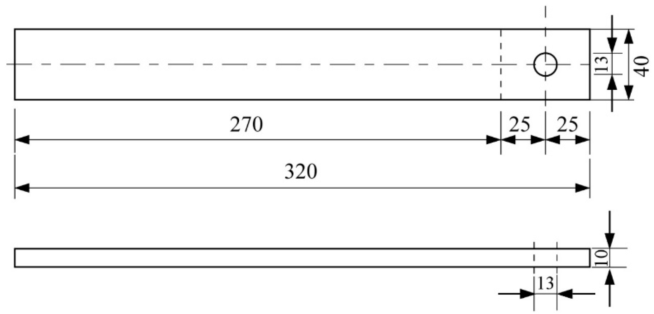
The bolt-jointed beam structure studied in this paper is shown in Figure 1, which consists of two perforated steel beams lapped together and connected by a bolt and nut. A steel washer with an outer diameter of 24 mm and an inner diameter of 12.5 mm was placed between the bolt and the steel beam, and another one was placed between the nut and the beam to provide a more uniform preload on the steel beam. The bolt is an engineering high-strength bolt with a diameter of 12 mm. The dimensions of the perforated steel plate are shown in Figure 2. When studying this type of structure, if the external load applied at the free end is parallel to the bolt axis, the beam is thin, and the modeling of the beam can use the Euler–Bernoulli beam model. However, if the external load is perpendicular to the bolt axis (transverse loading), the shear deformation and rotational inertia of the beam need to be considered, and the Timoshenko beam model should be adopted.
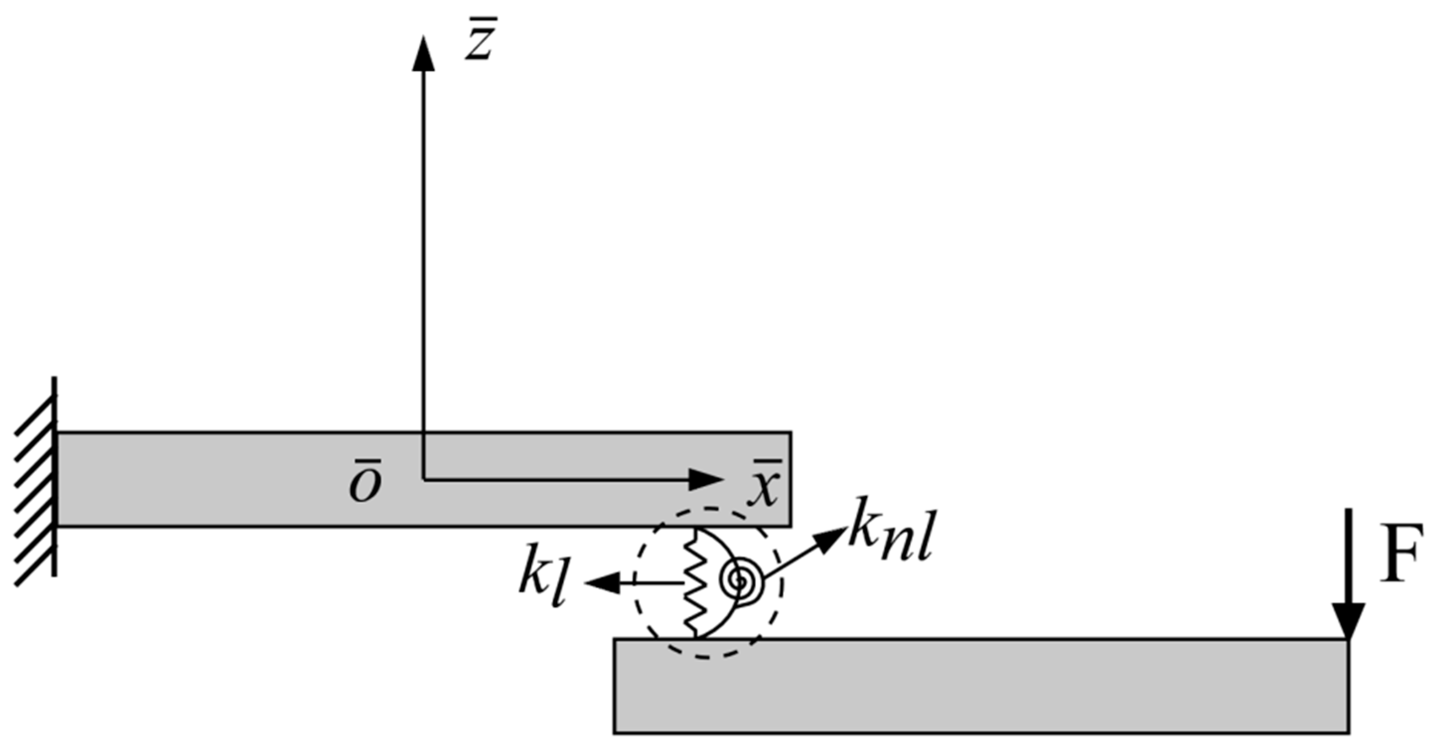
Abad [49] verified that the hysteresis loops in the tangential direction of a bolted lap joint could be well reproduced by direct numerical simulations using a FEM model with solid and contact elements. However, it is challenging to solve the problem of multi-scale modeling, and the enormous computational cost of the contact algorithm makes its application scenario very limited. Therefore, this section aims at the equivalent dynamic modeling of the bolt-jointed beam structures. Timoshenko beam elements were used for the beam components to simplify the solid elements. For the hysteresis characteristics of the jointed interfaces, a linear translational spring kl and a hysteretic rotational spring knl were used [44,50], as shown in Figure 3, where the force-displacement behavior of the hysteretic spring knl was based on the Valanis model.
The structure can be considered as two Timoshenko beams connected by nonlinear connecting elements whose differential equations of motion can be written as [51]:
M x ¨ ( t ) + C x ˙ ( t ) + K x ( t ) + F l ( x ( t ) ) + F n l ( x ( t ) , x ˙ ( t ) ) = F ( t )
where M is the global mass matrix, C is the Rayleigh damping matrix, K is the global stiffness matrix, Fl is the linear spring restoring force vector, Fnl is the nonlinear restoring force vector, and F(t) is the external load vector.
For an n-node structure with two degrees of freedom considered at each node, the nodal displacement vector x(t) has 2 ×  n elements, and the odd terms of the vector can be set to be the deflection of each node, whereas the even terms are the section angles. The external load vector has the same number of elements, and the odd term can be set to be the transverse load applied at the nodes, whereas the even term represents the applied bending moment. If a transverse load is applied at node q, then the external load vector F at this point can be expressed as:
F = [ 0 , , 0 , f ( t ) , 0 , , 0 2 n ] T ( 2 q 1 ) t h
Let the nodes connected by the linear and nonlinear springs of the bolted joint be node r and node l. The linear spring restoring force vector Fl can be expressed as:
F l = [ 0 , , 0 , f l ( w ( t ) ) , 0 , , 0 , f l ( w ( t ) ) , , 0 2 × n ] T ( 2 l 1 ) t h             ( 2 r 1 ) t h
where, w(t) is the relative transverse displacement at the joint of two steel beams, wl(t) and wr(t) represent the transverse displacement of node l and node r, respectively. The linear restoring force can be defined as:
f l = k l w ( t ) = k l ( w l ( t ) w r ( t ) ) = k l ( x 2 l 1 x 2 r 1 )
The relationship between the nonlinear restoring moment and the relative rotation of the joint is assumed to conform the differential equation of the Valanis model. Figure 4 shows a typical hysteresis curve for this model; the model is governed by the differential equation [30]:
M ˙ n l ( θ , θ ˙ ) = E 0 θ ˙ [ 1 + λ E 0 θ ˙ | θ ˙ | ( E t θ M n l ) ] 1 + κ λ E 0 θ ˙ | θ ˙ | ( E t θ M n l )
where Mnl is the nonlinear restoring moment, E0 represents the stiffness in the sticking regime, Et represents the stiffness in the macro-slip regime, the parameter κ controls the influence of micro-slip. The larger the value of κ, the closer the model is to the bilinear model. The parameter λ is defined by:
λ = E 0 σ 0 ( 1 κ E t E 0 )
where σ0 is the limit value of the sticking regime.
The nonlinear restoring force vector can be expressed as:
F n l = [ 0 , , 0 , M n l ( θ ( t ) , θ ˙ ( t ) ) , 0 , , 0 , M n l ( θ ( t ) , θ ˙ ( t ) ) , 0 , 0 ] ( 2 l ) t h                       ( 2 r ) t h  
where, θ ( t ) and θ ˙ ( t ) are the relative rotation and relative rotational velocity of the jointed interface. Let the angular displacements of node l and node r be θl(t) and θr(t), respectively, then θ ( t ) can be defined as:
θ ( t ) = θ l ( t ) θ r ( t ) = x 2 l x 2 r
To solve the differential equation of motion (1) in combination with the restoring force Equations (4) and (5), a state vector y is introduced as:
y = { x T x ˙ T M n l f l } T
Then, a first-order ordinary differential equation system can be obtained as:
dy dt = { x ˙ x ¨ M ˙ n l f ˙ l } = ( x ˙ M 1 ( F F l F n l C x ˙ K x ) E 0 θ ˙ ( t ) [ 1 + λ E 0 θ ˙ ( t ) | θ ˙ ( t ) | ( E t θ ( t ) M n l ) ] 1 + κ λ E 0 θ ˙ ( t ) | θ ˙ ( t ) | ( E t θ ( t ) M n l ) k l w ˙ ( t ) )
Equation (10) can be solved by the ODE45 solver in MATLAB software to obtain the dynamic response of the structure and the nonlinear restoring force of the bolted joint.

2.2. Calculation of the Beam Deformation Using Timoshenko Beam Elements

In order to simulate the deformation of the beam, the Timoshenko beam model considering shear deformation and rotational inertia is used in this paper, and the finite element method was used for modeling. The stiffness matrices and mass matrices of the Timoshenko beam elements are [52]:
K e = E I l 3 ( 1 + Φ ) [ 12 6 l 12 6 l ( 4 + Φ ) l 2 6 l ( 2 Φ ) l 2 12 6 l sym ( 4 + Φ ) l 2 ]
M v e = ρ A l 210 ( 1 + Φ ) 2 [ 78 + 147 Φ + 70 Φ 2 ( 44 + 77 Φ + 35 Φ 2 ) l 4 27 + 63 Φ + 35 Φ 2 ( 26 + 63 Φ + 35 Φ 2 ) l 4 ( 8 + 14 Φ + 7 Φ 2 ) l 2 4 ( 26 + 63 Φ + 35 Φ 2 ) l 4 ( 6 + 14 Φ + 7 Φ 2 ) l 2 4 78 + 147 Φ + 70 Φ 2 ( 44 + 77 Φ + 35 Φ 2 ) l 4 sym ( 8 + 14 Φ + 7 Φ 2 ) l 2 4 ]
M r e = ρ I 30 ( 1 + Φ ) 2 l [ 36 ( 3 15 Φ ) l 36 ( 3 15 Φ ) l ( 4 + 5 Φ + 10 Φ 2 ) l 2 ( 3 15 Φ ) l ( 1 + 5 Φ 5 Φ 2 ) l 2 36 ( 3 15 Φ ) l sym ( 4 + 5 Φ + 10 Φ 2 ) l 2 ]
where K e is the element stiffness matrices, M v e and M r e are the translational mass matrix and the rotational inertia mass matrix, respectively, l is the length of the beam, E is the elastic modulus, G is the shear modulus, ρ is the density, A is the cross-sectional area, I is the moment of inertia, k is the shear correction factor, Φ is the shear deformation parameter which can be calculated by:
Φ = 12 E I k G A l 2
By modeling the beam components in the equivalent model with Timoshenko beam elements, the global stiffness matrix K and mass matrix M in Equation (10) can be obtained as [53]:
K = e = 1 m K e
M = e = 1 m ( M v e + M r e )
In this paper, each beam component in the equivalent model was meshed with five Timoshenko beam elements, as shown in Figure 5, where the lengths of elements 4, 5, 6, and 7 are 0.25 m, and the lengths of the remaining elements are 0.9 m. The nodes at the bolt locations are connected by linear translational spring and nonlinear rotational spring.

3. FEM Contact Mechanics Analysis of the Bolted Joint

3.1. Solid FEM Model

In this section, the ANSYS software was used to build a 3D solid FEM model of the bolt-jointed beam structure, which has been proved accurate and effective in reproduction of the jointed surfaces [36,49,54,55] and can be used for validation [29,37]. The material parameters were set: elastic modulus E = 206 GPa, density ρ = 7850 kg/m3, and Poisson’s ratio ν = 0.3, and the beam and the joint components were meshed using SOLID185 elements. Before applying the excitation, a preload needs to be added, achieved by PRETS179 elements defined in the middle of the bolt shank. The simulation of contact surfaces between components was achieved by establishing contact pairs, and the contact surfaces and target surfaces are defined, as shown in Table 1. CONTA174 and TARGE170 elements were employed to simulate the surface-surface contact. The model used two types of contact modes: the standard unilateral contact and the “bonded” contact. When the contact mode is set to “bonded” contact, the contact between the bolt and the beam can be considered rigid connections, i.e., there is no normal separation or tangential slip, while the effect of the bolt mass is also taken into account. When the slip of the connection surface is considered, the contact is set to standard unilateral contact. In this type of contact, the normal pressure equals to zero if normal separation occurs. The contact mode of the contact surface between the bolt shank and the inner surface of the nut was set to “bonded”, and the rest of the contact surfaces were set to standard unilateral contact.
By setting the normal penalty stiffness factor kn and the tangent penalty stiffness factor kτ, it is available to control the contact and tangential stiffness values to aid in the convergence of the calculation while avoiding the penetration function and the elastic part of the slip being too large. The friction model adopts Coulomb type law, which assumes that the contact interface can withstand a certain amount of shear stress before the two contact surfaces slide against each other, and this is called sticking-type behavior. When the shear stress withstood reaches a limit value, the contact surfaces produce a sizeable relative sliding, and then sliding-type behavior is produced. The limit shear value follows [56]:
τ lim = μ P + b
here, μ is the friction coefficient, P is the contact pressure, and b is the contact cohesion. Parameter b can compensate for the ultimate shear stress without changing the contact pressure. Since the friction coefficient μ depends on the relative sliding velocity of the contact surface, the velocity-dependent exponential decay process of the friction coefficient is described by:
μ ( v ) = μ d + ( μ s μ d ) e c | v |
where μ d and μ s are the dynamic and static friction coefficients, respectively, c is the exponential coefficient decay, which controls the change from the static value to the dynamic value, v is the relative slip rate. The real constant settings used in this work adopt the parameters settings obtained from the quasi-static experimental fitting in the reference [49], as shown in Table 2, which have been used in the following mechanics analysis and the verification in Section 4. In this work, the diameters of the bolt holes of beams were 13 mm following DIN EN 20273 standard guidelines [57], which provided an adequate space for the slip of the joint. It is assumed that the displacement does not exceed the clearance between the bolt and the bolt hole of beams, which is common in many applications of civil engineering and machine design [36,45,46,58].

3.2. Influence of the Mesh Density

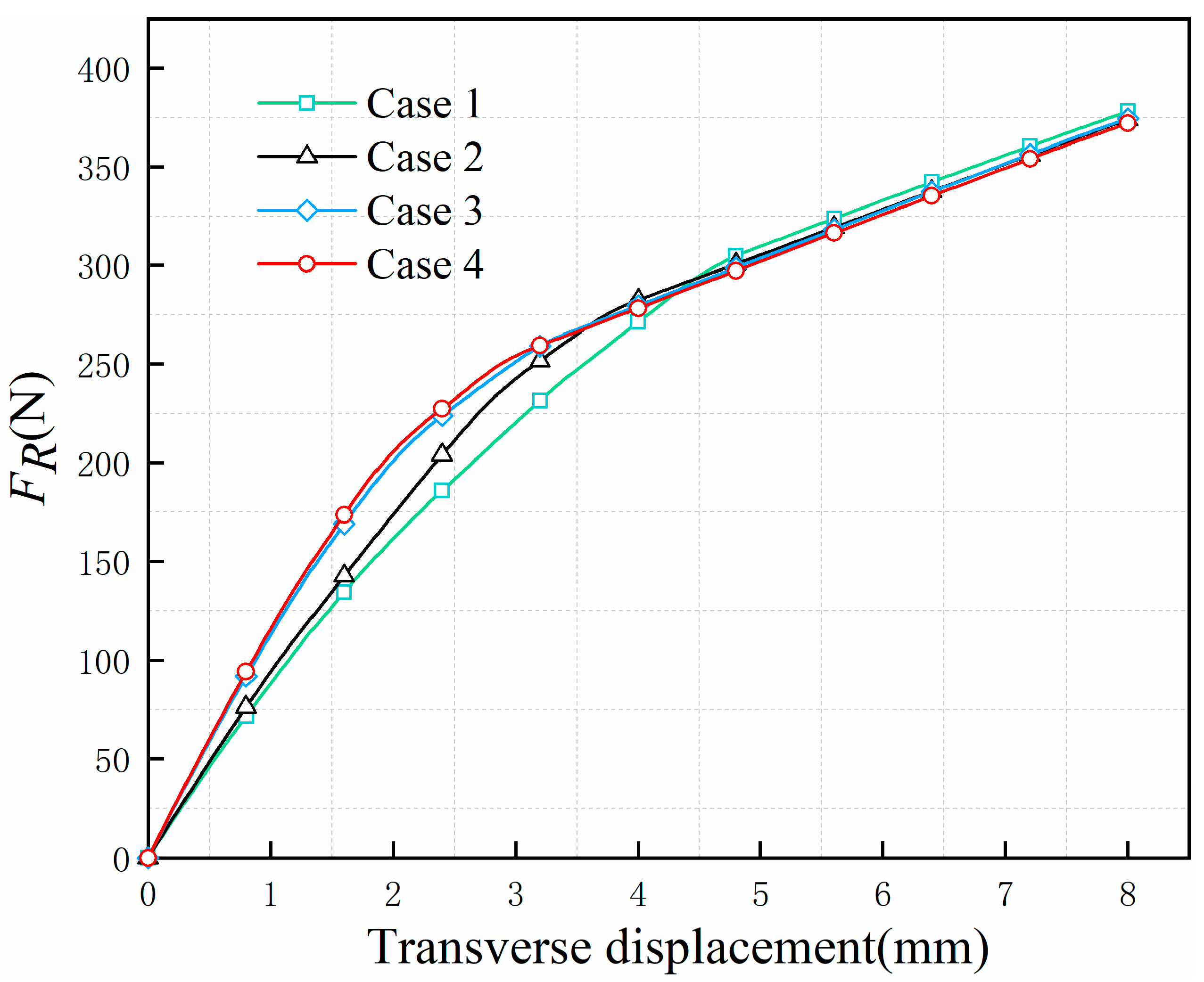
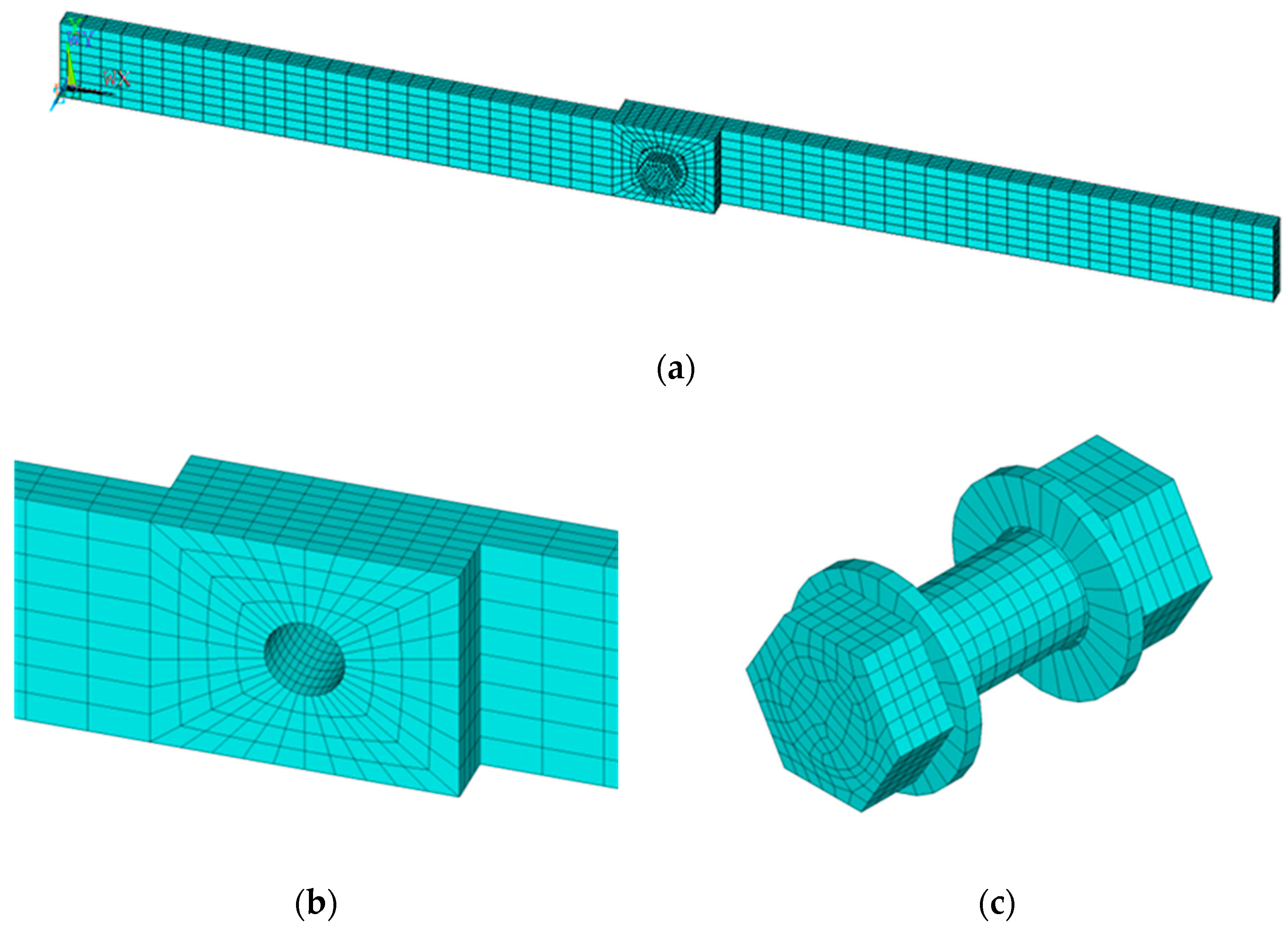
Though solid FEM models proved to be reliable in the reproduction of bolted joint behavior [54,55], analysis of assemblies with contact surfaces requires excessive computational CPU times when models are finely meshed, especially a transient dynamic analysis. Therefore, it is necessary to conduct a quasi-static experiment on the model to identify the mesh density that allows accurate simulation of the mechanical behavior of the jointed interfaces while reducing the computational cost. Four mesh densities were defined and a transverse displacement increasing linearly to 8 mm with time-steps was applied to the free end of the bolted joint beam model. The transverse reaction force FR at the free end of the beam was extracted, and the reaction force–displacement curves were plotted, as shown in Figure 6. The analysis was performed on a device consisting of Windows 10 64-bit, a 3.2 GHz AMD processor with 8 cores, and 16 Gb RAM (which was also used for the other sections that follow), Table 3 shows the running computation time for each mesh density. The results show that Case 3 can guarantee the accuracy of the calculation with the least computational cost, where the minimum mesh size is 2 mm. Figure 7 shows the mesh of the solid FEM model.

3.3. Static Analysis of the Solid FEM Model

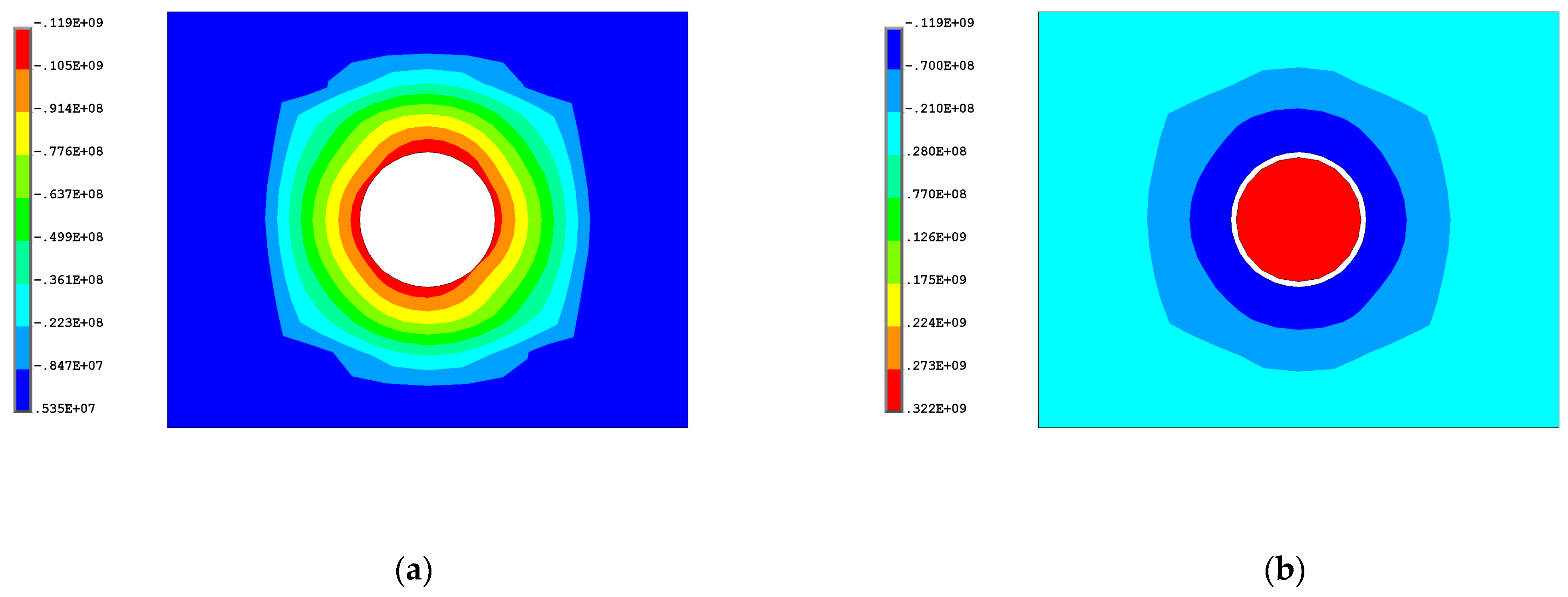
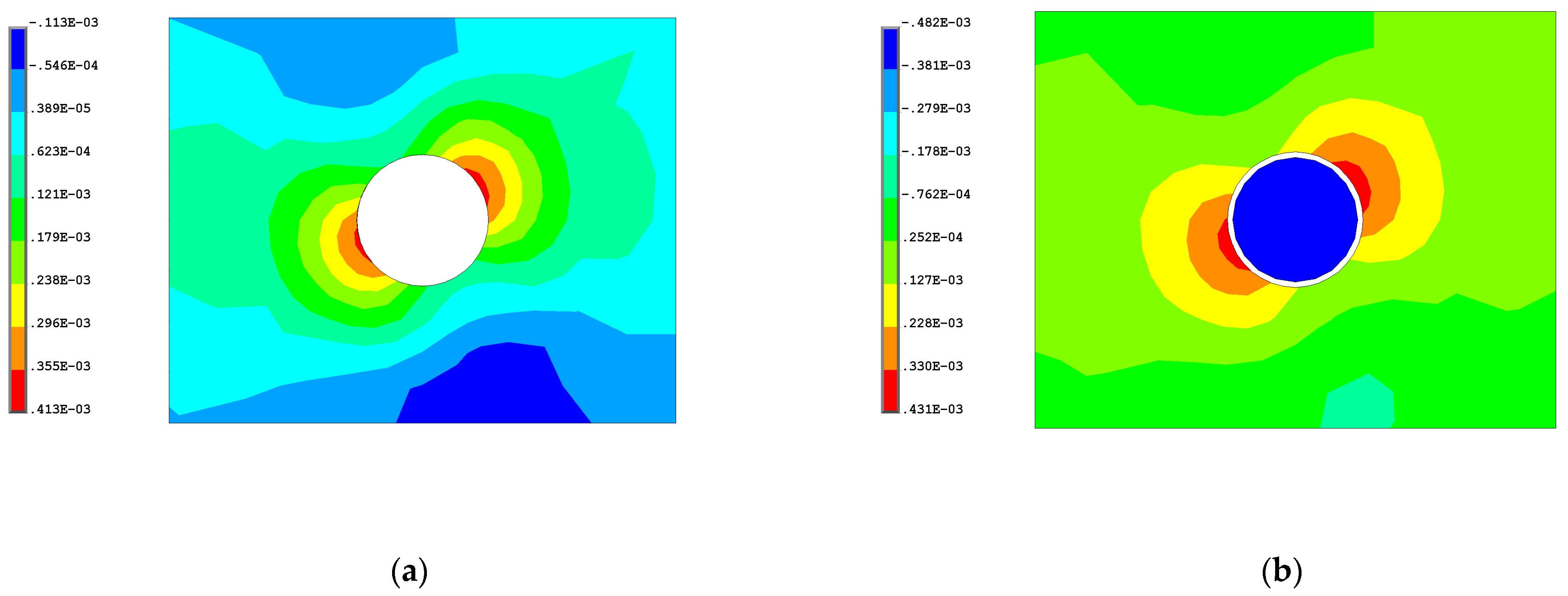
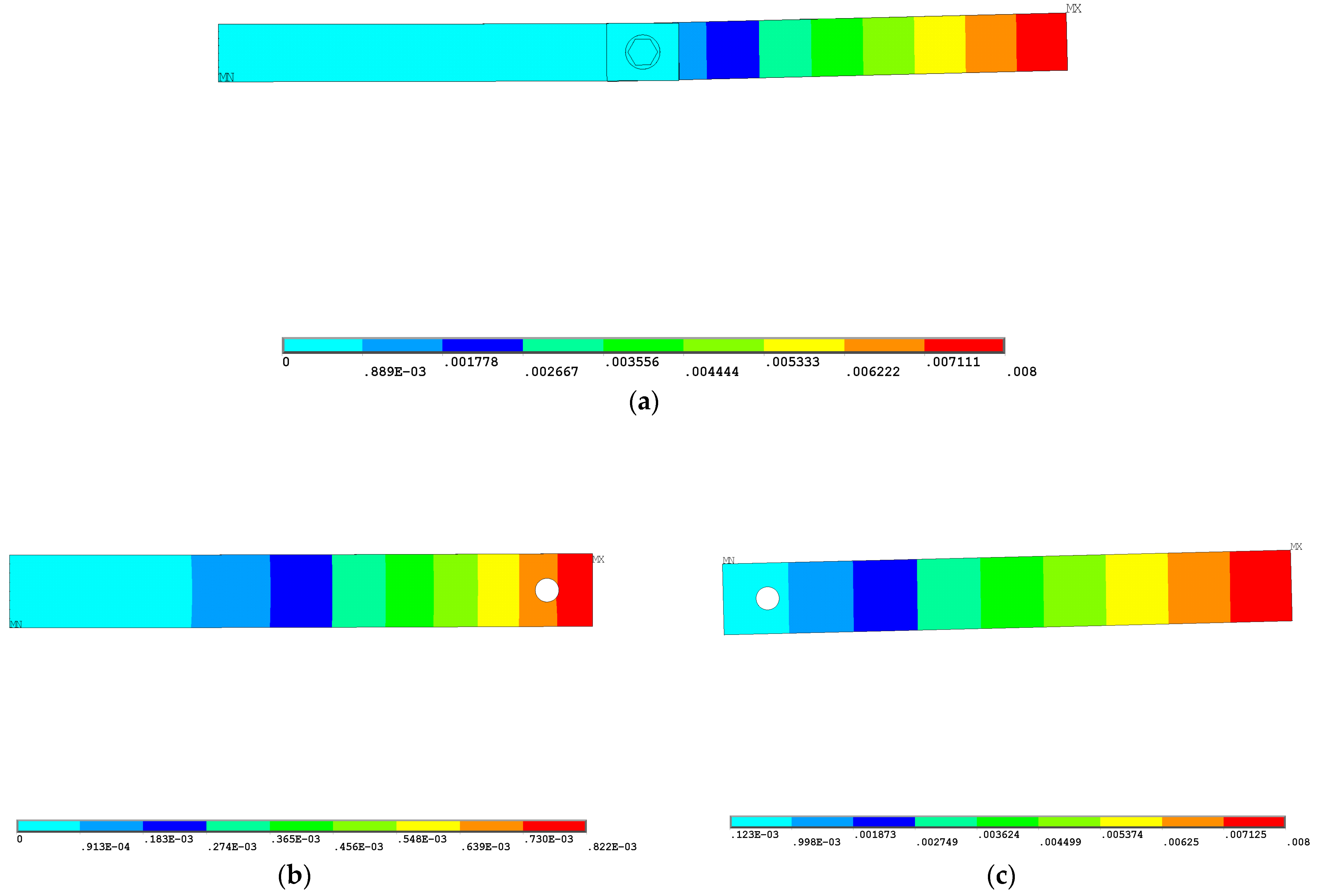
According to DIN-ISO 898 standard guidelines [59], the proof load for bolts with property class 8.8 and nuts with property class 8 that are widely used in assembled structures is 74.2 kN. Therefore, a range of 24.5 kN to 74.5 kN with an interval of 10 kN was chosen to be the preload level range. Setting the preload level equal to 34.5 kN, and the transverse displacement of the free end was 8 mm, the normal pressure distribution on the contact surface between beams is shown in Figure 8, which indicates that the preload was successfully applied to the bolt. Figure 9 shows the mechanical strain in the transverse direction, which presents the influence of the transverse displacement and friction force on strain. The transverse displacement of the assembled system has been shown in Figure 10, and it can be observed that the bolted beam has a rotation at the joint, which is consistent with the assumption of the equivalent model.
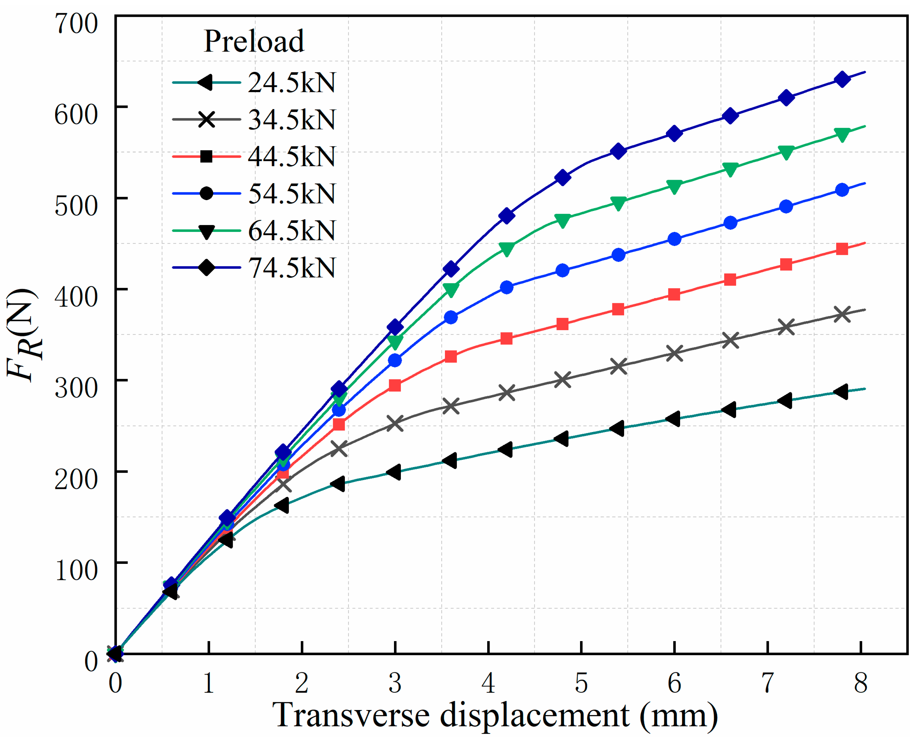
Then, the free end of the solid FEM model was loaded transversely by controlled displacement, which increased linearly with time steps, and the maximum transverse displacement was 8 mm. Figure 11 shows the reaction force–displacement curves under different preload levels.
It can be seen from Figure 11 that under the selected preload levels, the relationship between the reaction force FR and the displacement d of the cantilevered beam was nonlinear. When the bolted lap was in the sticking state, it behaved in a linear elastic mode, and the tangential contact stiffness was relatively large at this time, expressed by the parameter E0; when the tangential displacement keeps increasing, and the tolerable shear stress reached the limit value σ0, the stiffness gradually decreased and transitioned to the macro-slip regime, at which, the stiffness was the residual stiffness, expressed by the parameter Et.
However, the displacement of the hysteresis loop includes the deflection of the beam, which is very small and negligible when the steel beam is loaded axially, while quite different when the structure is excited transversely. By setting the contact mode of the solid FEM model to “bonded” and applying the chosen excitation to the free end, the stiffness of the beam kb under transverse load can be obtained. The stiffness of the beam in this example is kb = 164,488 N/m, which is a constant, indicating that the excitation amplitude is far from the yield strength of the steel. The relationship between the displacement db and the transverse reaction force obeys [60]:
d b = F R k b
If the tangential slip at the bolt was w, the relative rotation was θ , the restoring moment was Mnl, and the force arm from the free end to the bolt was Lb, then the following system of equations can be obtained:
{ d = d b + w + θ L b F R = f l = k l w M n l = F R L b = k n l θ
After obtaining the dynamic response d of the free end, the beam deflection db, the linear spring stiffness kl, and the linear tangential restoring force fl, the relationship between the nonlinear restoring moment Mnl and the relative rotation θ of the bolted lap joint can be obtained by solving the above system of equations, as shown in Figure 12. It can be concluded that the stiffness of the joint in the sticking regime was little influenced by the bolt preload level, and the corresponding parameter E0 can be seen as constant. The residual stiffness Et showed a slight increase with the increasing preload. The limit threshold of the sticking regime, which corresponds to σ0, increased significantly with a higher preload level. According to Equation (17), the threshold is also related to the friction coefficient of the friction surface, and increases with increasing friction coefficient μ.

4. Results and Discussion

4.1. Validation of the Deformation of the Timoshenko Beam Model

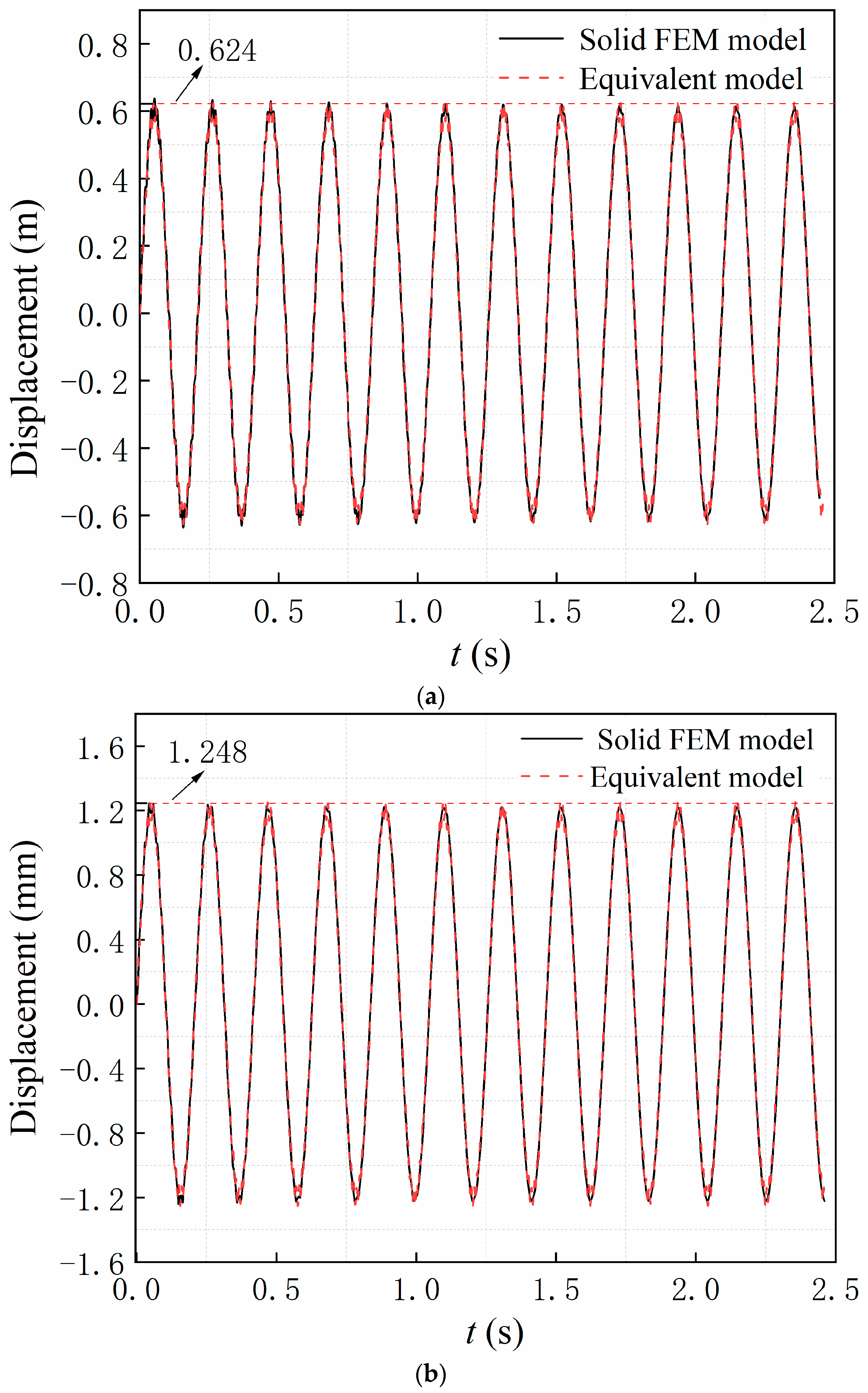
To verify the accuracy of using Timoshenko beam elements to simulate deflections resulting from beam deformation, the solid FEM model constructed in Section 3 using SOLID185 element and CONTA174 element was used for comparison. The contact mode of the solid FEM model was set to “bonded” contact, and the equivalent model was coupled in all degrees of freedom at the two nodes connected by springs. With the above preparation, no relative sliding and rotation will occur at the jointed interfaces of the equivalent and the FEM models, and the contact surfaces can be considered rigid. The transverse direction of the free end of the model was loaded twice, and the applied excitation is a harmonic load F = F0·sin(ω·t), where the amplitudes F0 of the two excitations were set to 100 N and 200 N, and the angular frequency ω is taken as 30 rad/s. The dynamic responses of the FEM model and the equivalent model are shown in Figure 13.
Figure 13 shows the displacement amplitudes of the FEM model and the equivalent model equal under the same excitation. The displacement amplitude is 0.624 mm for an excitation amplitude of 100 N and 1.248 mm for an excitation amplitude of 200 N. The excitation amplitude was proportional to the displacement amplitude, which is consistent with the characteristics of a linear structure. The results show that the finite element algorithm used in the equivalent model can accurately calculate the deflection generated by the deep beam under transverse excitation.

4.2. Validation of the Equivalent Model of the Bolt-Jointed Beam

In order to obtain the hysteresis loops through the solid FEM model, it is necessary to force the free end of the cantilevered beam to undergo transverse displacement and extract the restoring force. The amplitude d0 of the applied displacement is the steady-state response amplitude obtained by applying a transverse harmonic excitation F = F0·sin(ω·t) to the cantilevered beam, where F0 is the harmonic excitation amplitude, and ω is the angular frequency. F0 was set to be 240, 270, 285, and 300 N, respectively, and ω was set to 30, 50, 70, and 90 rad/s, respectively. A total of 16 tests were performed in four groups, which required over 20 h for each calculation.
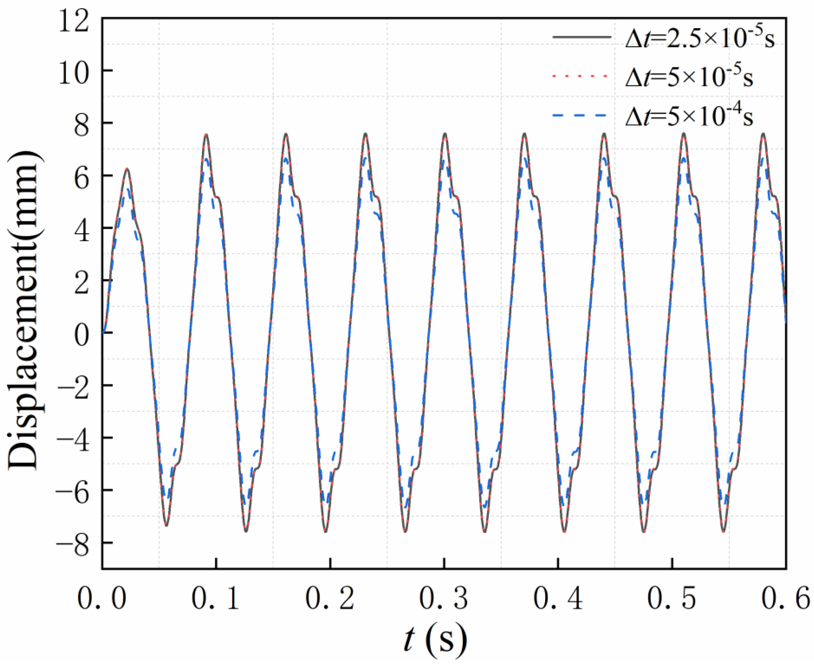
When the structure is excited, if the time step is too large, the steady-state amplitude obtained from the nonlinear transient dynamics analysis will be small. The time step used in these finite element tests was 0.00005 s, which was identified from a time step test, where F0 = 300 N, ω = 90 rad/s, and the time step Δt was set equal to 0.0005, 0.00005, and 0.000025 s. Figure 14 shows the result of the dynamic response comparison, which indicates that the time step was small enough to ensure an accurate dynamic response.
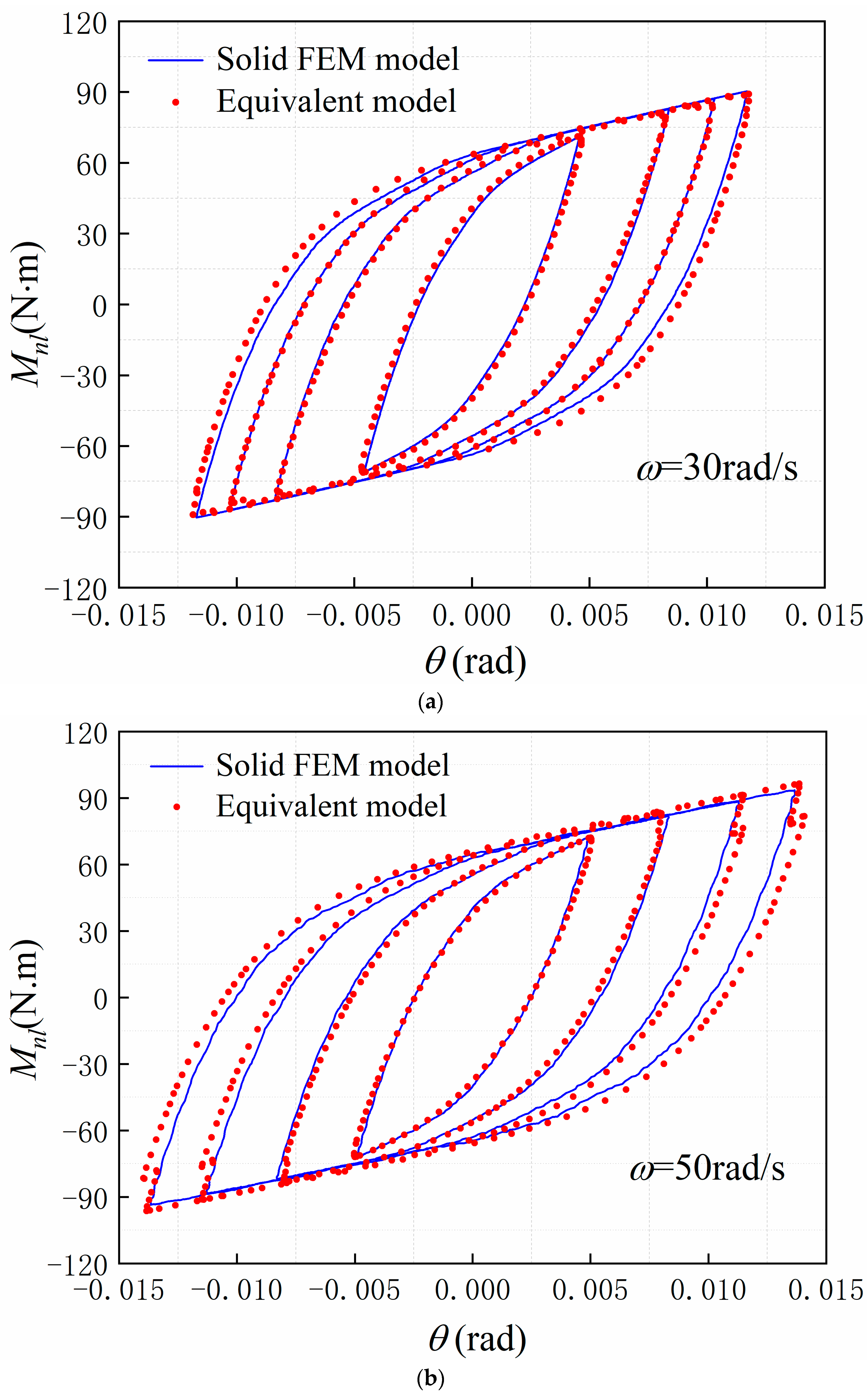
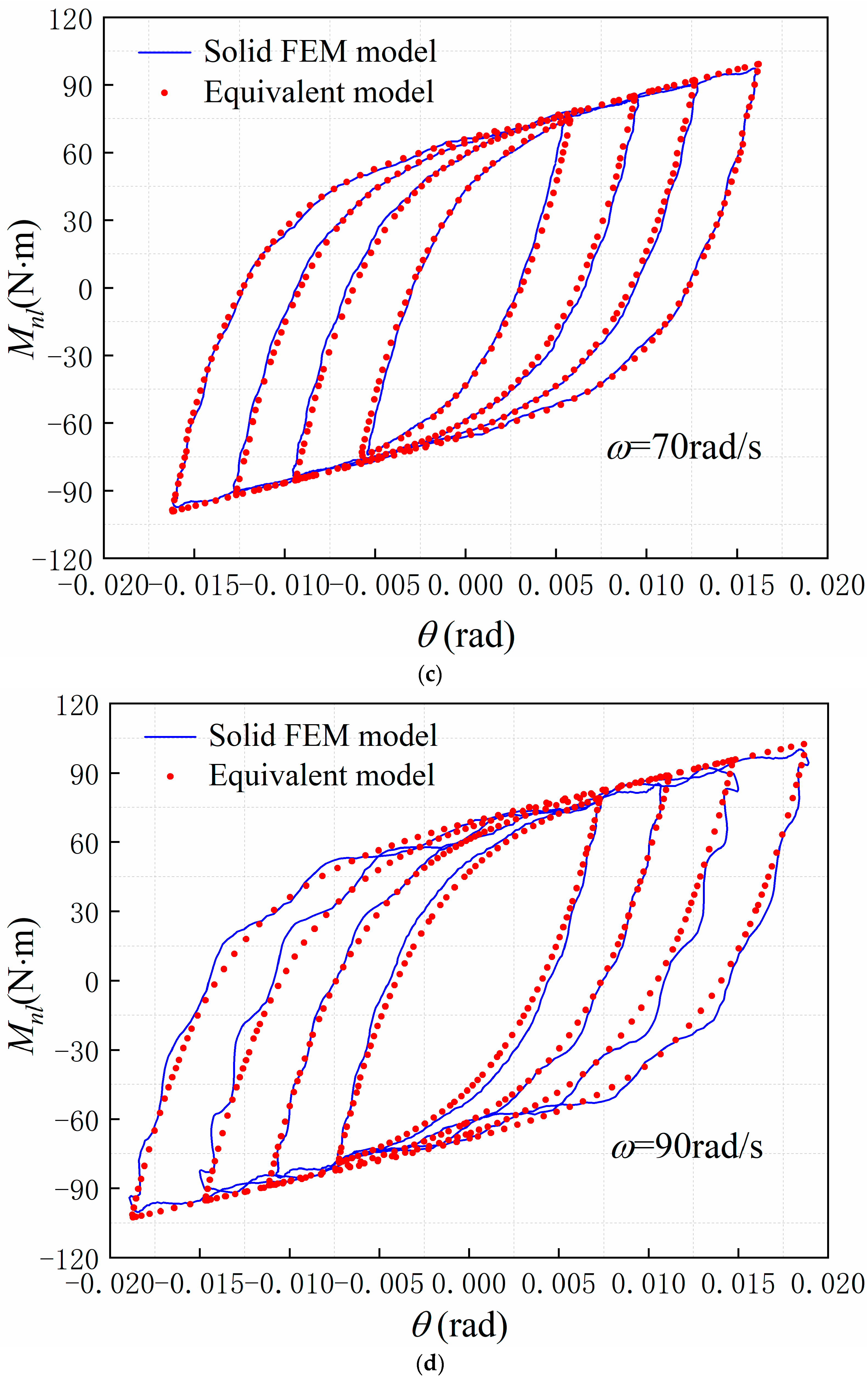
After obtaining the steady-state response for each calculation, the amplitude d0 of each harmonic excitation was used to control the free end displacement of the beam, and the forced displacement d follows d = d0·sin(ω·t). The moment–rotation curve was fitted using the Valanis model, and the results are shown in Figure 15. The parameters used in the equivalent model are shown in Table 4
As can be seen from Figure 15, the curves extracted by nonlinear transient analysis using the above method are smooth at the excitation frequency of 30, 50, and 70 rad/s. At the excitation frequency of 90 rad/s, the extracted hysteresis loops have a particular curvature, which indicates that the quality of the hysteresis loops extracted by the solid FEM model decreases to some extent with the increase of the excitation frequency.
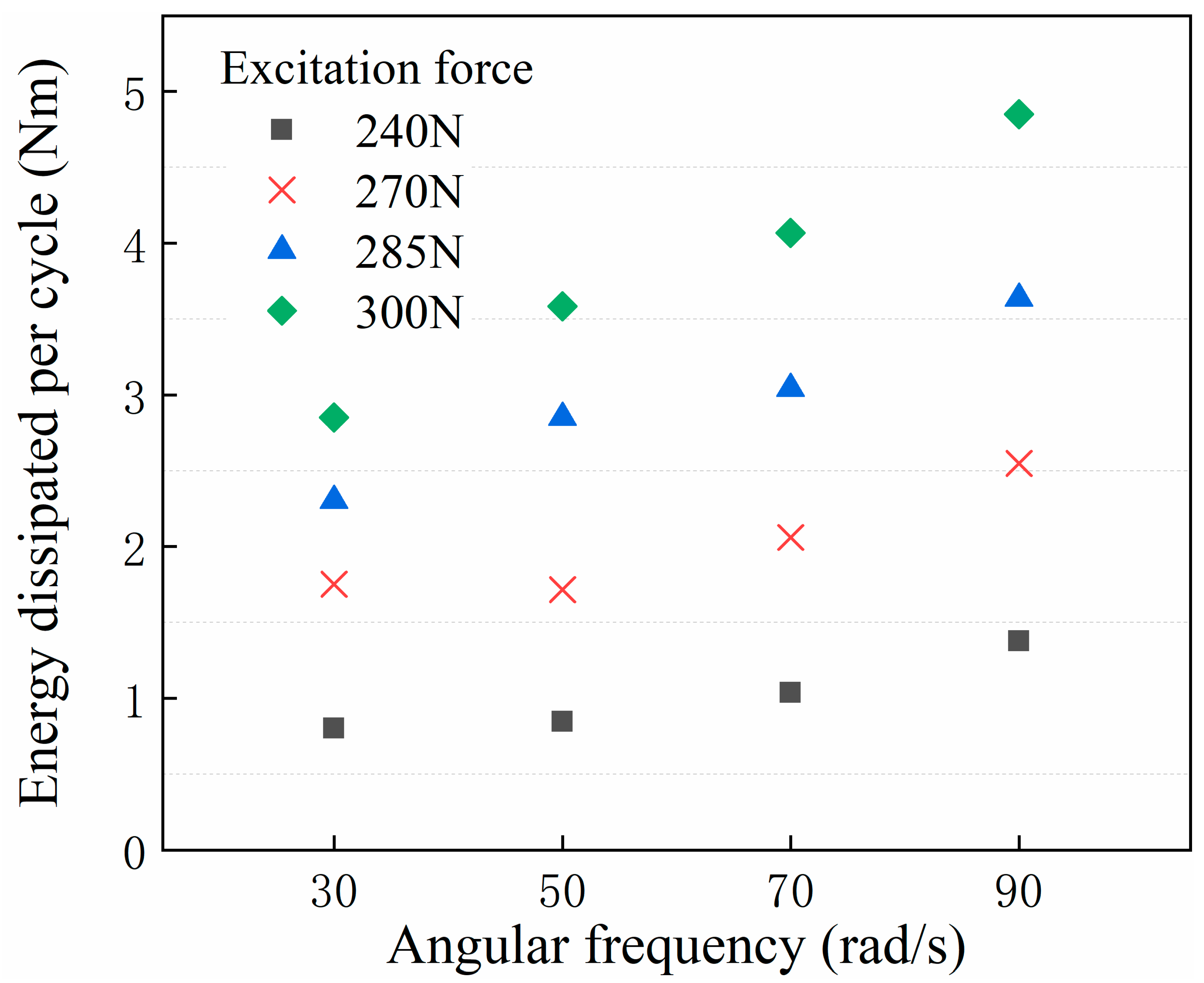
The area enclosed by the hysteresis loop, illustrated in Figure 15, represents the amount of external energy dissipated into internal energy thanks to the work done by friction forces [61] that have a non-conservative nature. The dissipations per cycle under different excitation frequencies and excitation amplitude are shown in Figure 16. In order to quantify the fitting effect, the correlation coefficient Ce was used, and the closer the Ce was to 1, the better the fitting effect:
C e = A e A o
where Ae is the single lag cycle area of the equivalent model, and Ao is the single lag cycle area obtained by nonlinear transient analysis of the FEM model. As shown in Figure 17, each fitted Ce was between 0.9 and 1.1, with a maximum value of 1.061 and a minimum value of 0.917. Most of the fitted Ce are between 0.95 and 1.05.
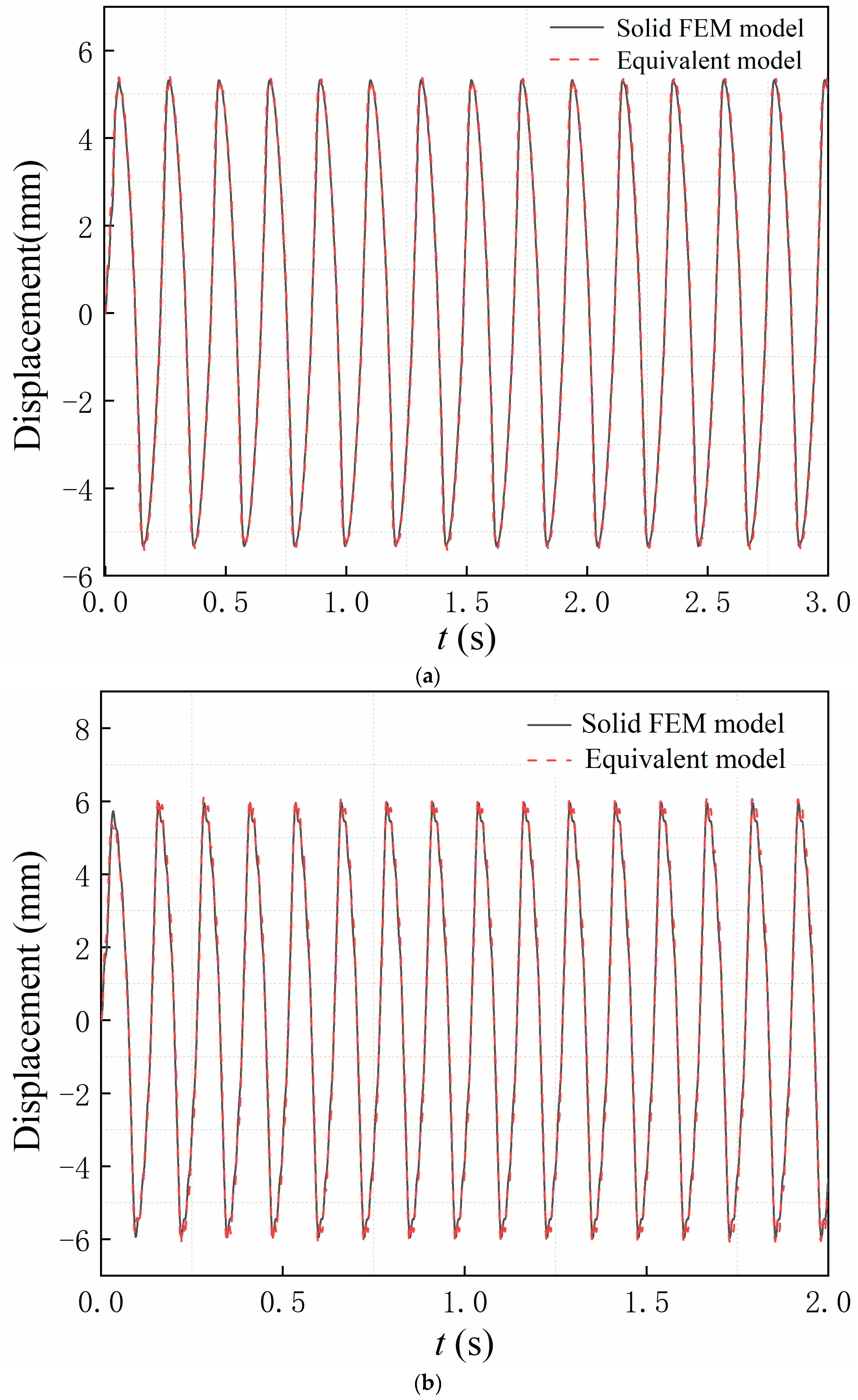
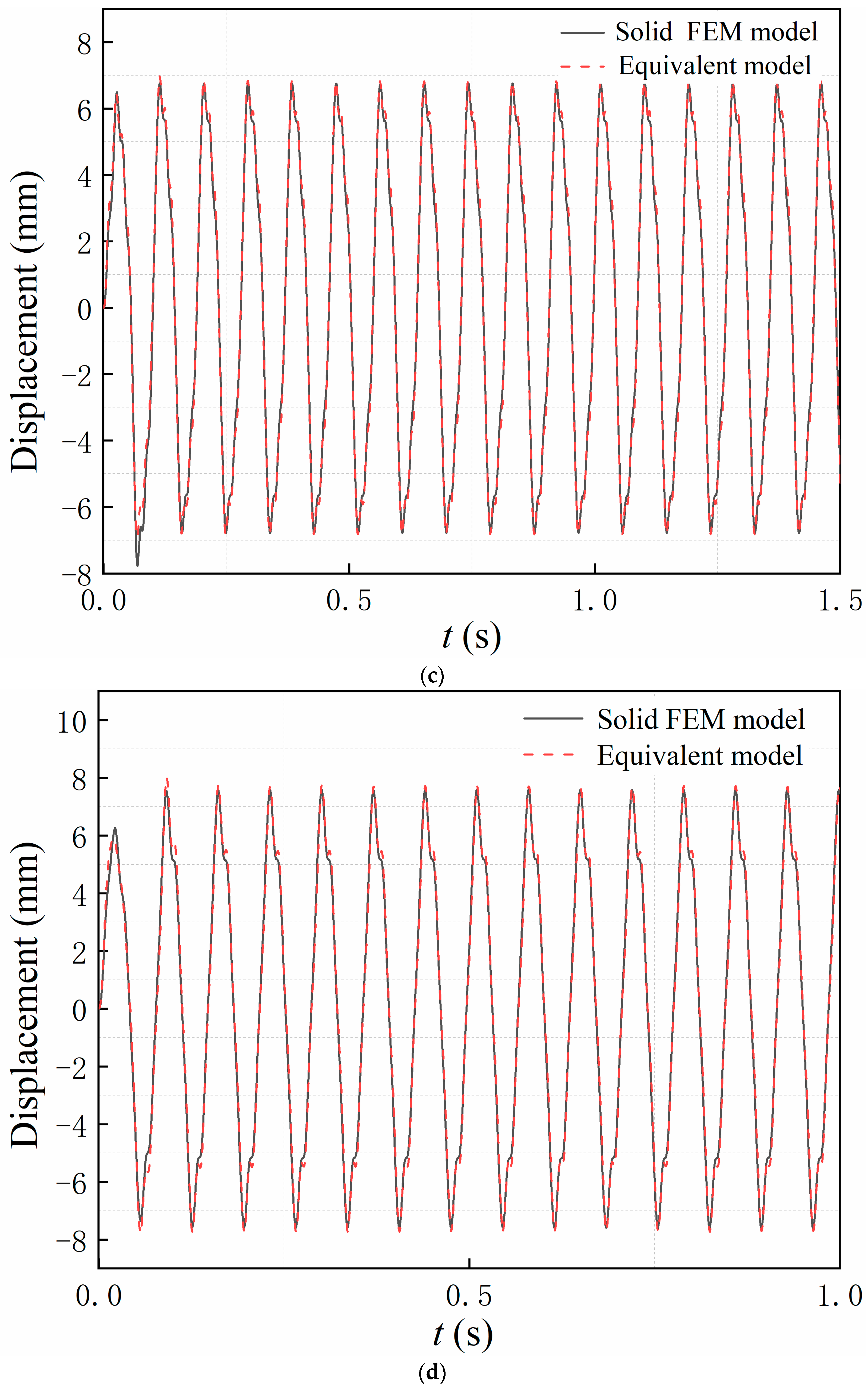
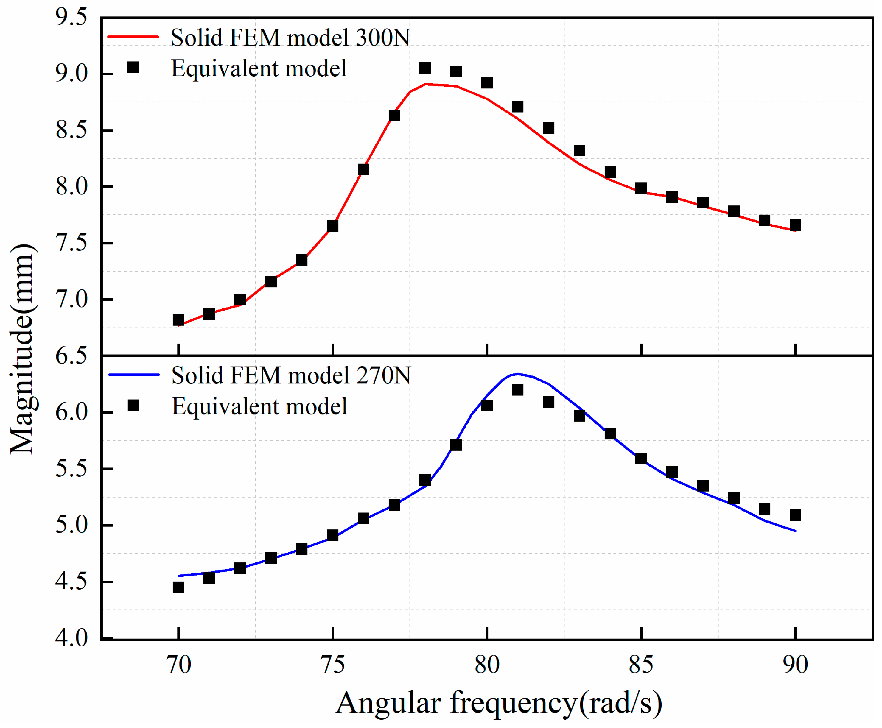
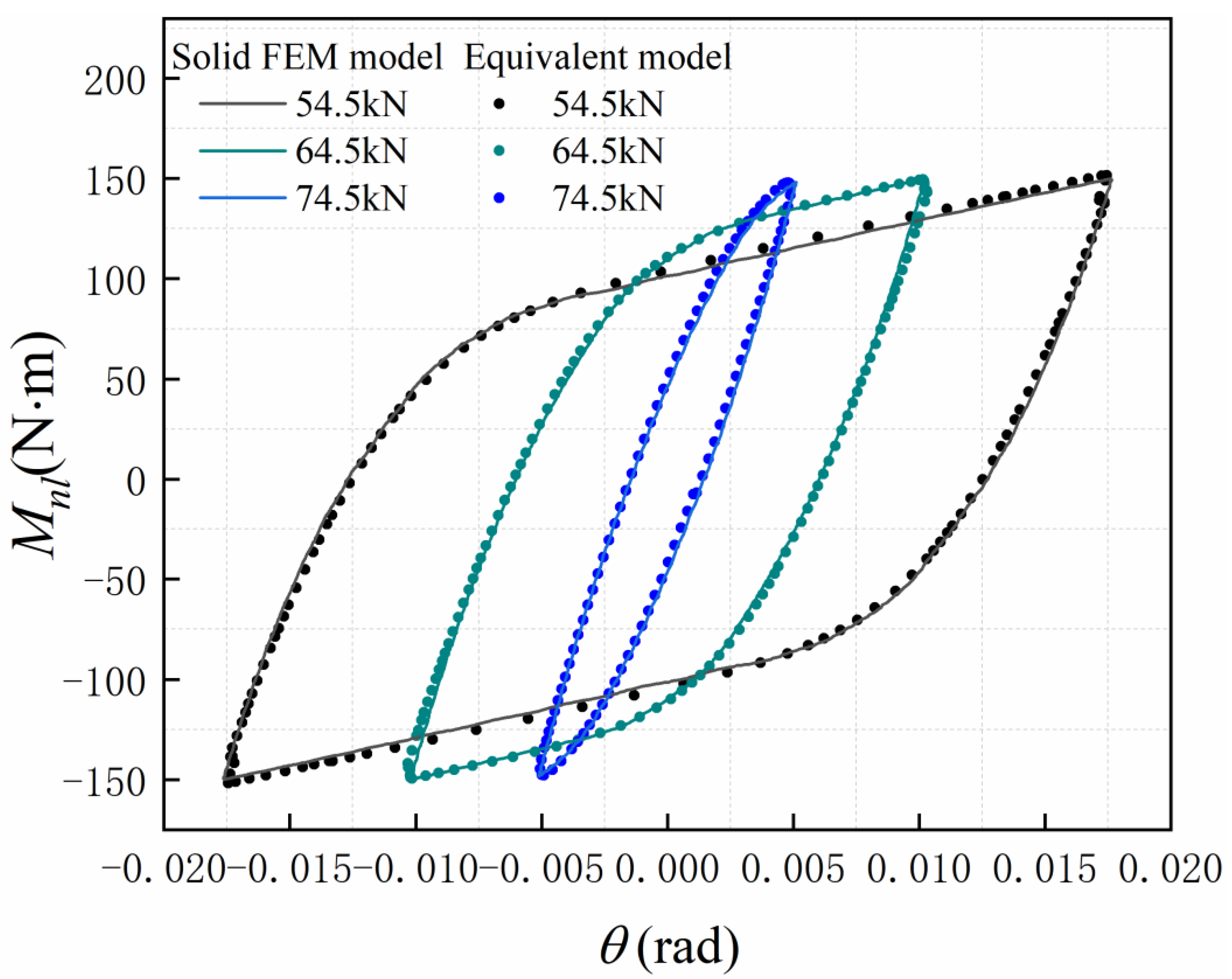
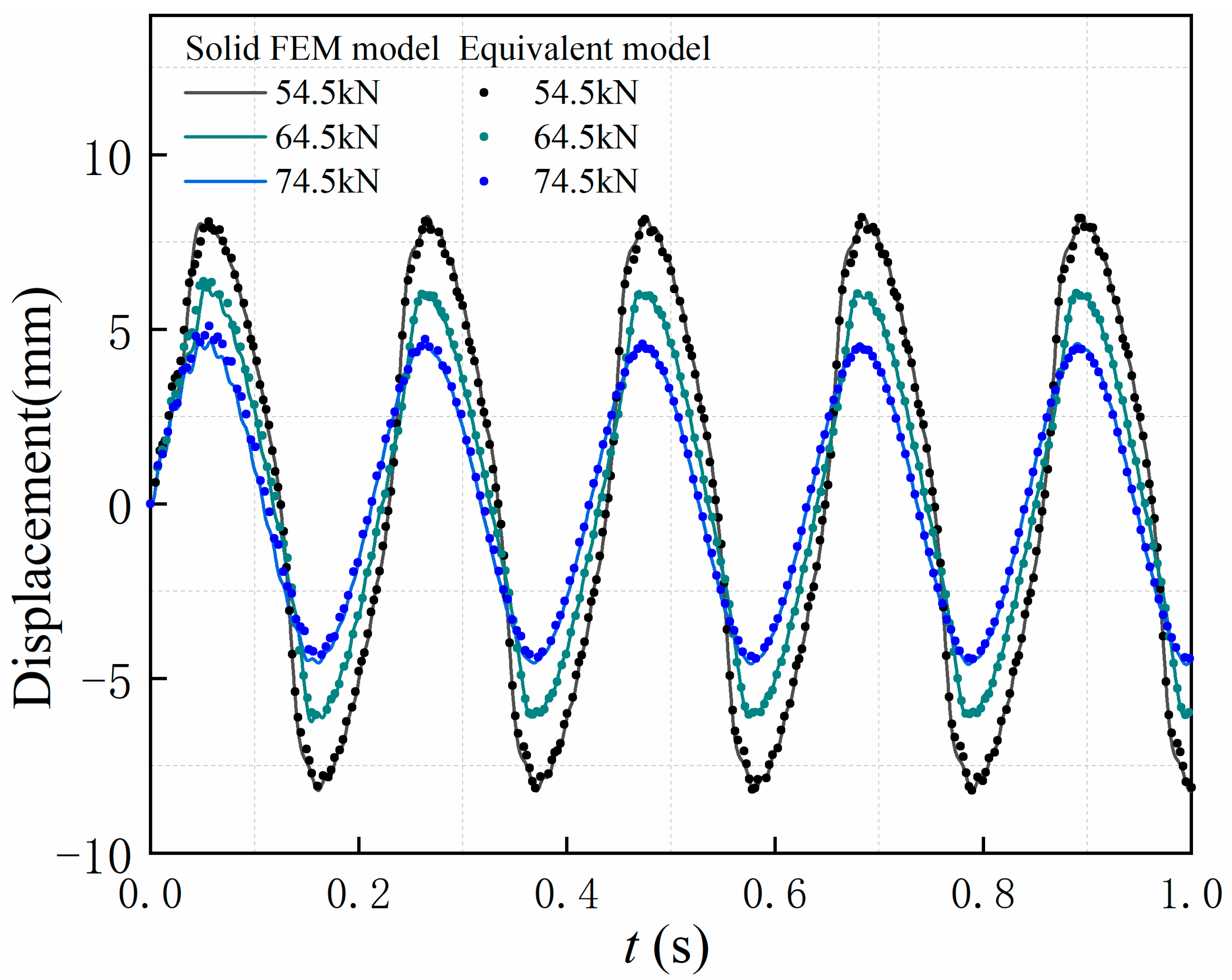
In order to verify the predictive ability of the constructed equivalent model, the same harmonic excitation f = F0·sin (ω·t) was applied to the free end of the equivalent model, and the dynamic response of its free end was compared with the solid FEM model. Figure 18 shows the comparison of the dynamic responses at F0 = 300 N, and the rest of the results and errors are given in the Table 5. The maximum error of the dynamic response magnitude is 5.5%, and the errors of most of the response magnitudes are within 3%. In addition, a range of frequencies near the first-order resonant frequency was chosen, and the excitation amplitude F0 was set equal to 270 N and 300 N. The amplitude-frequency response of the bolted beam evaluated by the equivalent model and the solid FEM model are compared in Figure 19. It can be concluded that the frequency response evaluated by the equivalent model is close to that of the solid FEM model when the excitation frequency lies near the first-order resonant frequency. The applicability of the equivalent model to different preload levels was verified using the method as above. The solid FEM models with preload levels of 54.5 kN, 64.5 kN, and 74.5 kN were applied with the same transverse excitation at the free end, where F0 was set equal to 500 N and the angular frequency ω was set equal to 30 rad/s. The hysteresis curves fitted by the Valanis model for different preload levels are shown in Figure 20, and the response comparison of the equivalent model and the solid FEM model is shown in Figure 21. The results indicate that the equivalent model is applicable for different preload levels. In addition, as the preload level increased, limit threshold of the sticking regime increased, and the area enclosed by the hysteresis loop decreased significantly, which indicates that the energy dissipated by the frictional effect of the contact surfaces will decrease under the same excitation.

5. Conclusions

In this paper, an equivalent modeling method for the rotation of a bolted lap joint was presented, where a nonlinear spring based on the Valanis model was used to simulate the rotational stiffness of the joint, and a linear spring was used to simulate the tangential stiffness of the joint. Deformation of the beam components under dynamic loads was considered through Timoshenko beam elements. This modeling approach can effectively reduce computational costs. The structural dynamics calculation for evaluating the dynamic response of 1 s takes only about 10 s, which is significantly more efficient than the 10 h required for DNS. In addition, the contact of the connection interface was simulated using CONTA174 and TARGE170 elements in ANSYS, and a 3D solid FEM model was built to validate the equivalent model. At the selected frequencies, where the highest excitation frequency was 90 rad/s, the accuracy of the fitted hysteresis loops was examined by comparing the dissipation correlation, which ranged from 0.917 to 1.061, with a maximum error of 8.3%, while most of the results were within 5% error. The dynamic responses of the structure evaluated by the equivalent model were compared with those of the solid FEM model under harmonic excitation, and a maximum error of 5.5% was found for the amplitude. In addition, a range of frequencies near the first-order resonant frequency was chosen to excite the studied bolted beam, and the amplitude–frequency response of the bolted beam evaluated by the equivalent model and the solid FEM model were compared. The results show that the frequency response evaluated by the equivalent model is very close to that of the solid FEM model. The proposed modeling approach can capture the nonlinear characteristics of the bolt-jointed interface, as well as accurately predicts the dynamic response and dissipation of the structure under different preload levels.

Author Contributions

G.Z. contributed to investigation, validation, software, and writing—original draft, F.L. contributed to methodology, supervision, writing—review & editing, and project administration. All authors have read and agreed to the published version of the manuscript.

Funding

This work was funded by the National Natural Science Foundation of China (grant number 12172181).

Institutional Review Board Statement

Not applicable.

Informed Consent Statement

Not applicable.

Data Availability Statement

Not applicable.

Conflicts of Interest

The authors declare no conflict of interest.

References

  1. Gaul, L.; Nitsche, R. The role of friction in mechanical joints. Appl. Mech. Rev. 2001, 54, 93–106. [Google Scholar] [CrossRef]
  2. Xiao, H.F.; Shao, Y.M.; Xu, J.W. Investigation into the energy dissipation of a lap joint using the one-dimensional microslip friction model. Eur. J. Mech. A -Solids 2014, 43, 1–8. [Google Scholar] [CrossRef]
  3. Wang, Y.; Liu, Y.; Wang, J.; Zhang, J.; Zhu, X.; Xu, Z. Research on process planning method of aerospace engine bolt tightening based on digital twin. Machines 2022, 10, 1048. [Google Scholar] [CrossRef]
  4. Chen, W.; Jin, M.; Lawal, I.; Brake, M.R.W.; Song, H. Measurement of slip and separation in jointed structures with non-flat interfaces. Mech. Syst. Signal Process. 2019, 134, 106325. [Google Scholar] [CrossRef]
  5. Li, Y.; Hao, Z. A six-parameter Iwan model and its application. Mech. Syst. Signal Process. 2016, 68, 354–365. [Google Scholar] [CrossRef]
  6. Mathis, A.T.; Balaji, N.N.; Kuether, R.J.; Brink, A.R.; Brake, M.R.W.; Quinn, D.D. A review of damping models for structures with mechanical joints. Appl. Mech. Rev. 2020, 72, 040802. [Google Scholar] [CrossRef]
  7. Woodhouse, J. Linear damping models for structural vibration. J. Sound Vib. 1998, 215, 547–569. [Google Scholar] [CrossRef]
  8. Zhao, Y.W.; Maietta, D.M.; Chang, L. An asperity microcontact model incorporating the transition from elastic deformation to fully plastic flow. J. Tribol. 2000, 122, 86–93. [Google Scholar] [CrossRef]
  9. Kogut, L.; Etsion, I. Elastic-plastic contact analysis of a sphere and a rigid flat. J. Appl. Mech. 2002, 69, 657–662. [Google Scholar] [CrossRef] [Green Version]
  10. Cohen, D.; Kligerman, Y.; Etsion, I. A model for contact and static friction of nominally flat rough surfaces under full stick contact condition. J. Tribol. 2008, 130, 117–139. [Google Scholar] [CrossRef]
  11. Lei, S.; Mao, K.; Tian, W.; Li, L. A Three-dimensional transition interface model for bolt joint. Machines 2022, 10, 511. [Google Scholar] [CrossRef]
  12. Song, Y.; Hartwigsen, C.J.; McFarland, D.M.; Vakakis, A.F.; Bergman, L.A. Simulation of Dynamics of Beam Structures With Bolted Joints Using Adjusted Iwan Beam Elements. J. Sound Vib. 2004, 273, 249–276. [Google Scholar] [CrossRef]
  13. Bouc, R. A mathematical model for hysteresis. Acta Acust. United Acust. 1971, 24, 16–25. [Google Scholar]
  14. Wen, Y.K. Method for random vibration of hysteretic systems. J. Eng. Mech. 1976, 102, 246–263. [Google Scholar] [CrossRef]
  15. Valanis, K.C. Fundamental consequences of a new intrinsic time measure. plasticity as a limit of the endochcronic theory. Archiv. Mech. 1980, 32, 171–191. [Google Scholar]
  16. Segalman, D.J. A four-parameter Iwan model for lap-type joints. J. Appl. Mech. 2005, 72, 752–760. [Google Scholar] [CrossRef] [Green Version]
  17. Ismail, M.; Ikhouane, F.; Rodellar, J. The hysteresis Bouc-Wen model, a survey. Arch. Comput. Methods Eng. 2009, 16, 161–188. [Google Scholar] [CrossRef]
  18. Hurtado, J.E.; Barbat, A.H. Equivalent linearization of the Bouc–Wen hysteretic model. Eng. Struct. 2000, 22, 1121–1132. [Google Scholar] [CrossRef]
  19. Jalali, H. An alternative linearization approach applicable to hysteretic systems. Commun. Nonlinear Sci. 2014, 19, 245–257. [Google Scholar] [CrossRef]
  20. Chakraborty, G. Equivalent linearization of Bouc–Wen hysteretic model with harmonic input. J. Inst. Eng. India Ser. C 2019, 100, 907–918. [Google Scholar] [CrossRef]
  21. Lacayo, R.M.; Allen, M.S. Updating structural models containing nonlinear Iwan joints using quasi-static modal analysis. Mech. Syst. Signal Process. 2019, 118, 133–157. [Google Scholar] [CrossRef]
  22. Ahmadian, H.; Rajaei, M. Identification of Iwan distribution density function in frictional contacts. J. Sound Vib. 2014, 333, 3382–3393. [Google Scholar] [CrossRef]
  23. Zaman, M.A.; Sikder, U. Bouc–Wen hysteresis model identification using modified firefly algorithm. J. Magn. Magn. Mater. 2015, 395, 229–233. [Google Scholar] [CrossRef]
  24. Ortiz, G.A.; Alvarez, D.A.; Bedoya-Ruíz, D. Identification of Bouc-Wen type models using the transitional Markov chain Monte Carlo method. Comput. Struct. 2015, 146, 252–269. [Google Scholar] [CrossRef]
  25. Oldfield, M.; Ouyang, H.; Mottershead, J.E. Simplified models of bolted joints under harmonic loading. Comput. Struct. 2005, 84, 25–33. [Google Scholar] [CrossRef]
  26. Wong, C.W.; Ni, Y.Q.; Ko, J.M. Steady-state oscillation of hysteretic differential model-II: Performance analysis. J. Eng. Mech. 1994, 120, 2299–2325. [Google Scholar] [CrossRef]
  27. Vaiana, N.; Sessa, S.; Rosati, L. A generalized class of uniaxial rate-independent models for simulating asymmetric mechanical hysteresis phenomena. Mech. Syst. Signal Process. 2021, 146, 106984. [Google Scholar] [CrossRef]
  28. Vaiana, N.; Rosati, L. Classification and unified phenomenological modeling of complex uniaxial rate-independent hysteretic responses. Mech. Syst. Signal Process. 2023, 182, 109539. [Google Scholar] [CrossRef]
  29. Jamia, N.; Jalali, H.; Taghipour, J.; Friswell, M.I.; Khodaparast, H.H. An equivalent model of a nonlinear bolted flange joint. Mech. Syst. Signal Process. 2021, 153, 107507. [Google Scholar] [CrossRef]
  30. Gaul, L.; Lenz, J. Nonlinear dynamics of structures assembled by bolted joints. Acta Mech. 1997, 125, 169–181. [Google Scholar] [CrossRef]
  31. Liu, F.S.; Wang, L.B.; Jin, D.P.; Liu, X.D.; Lu, P.L. Equivalent beam model for spatial repetitive lattice structures with hysteretic nonlinear joints. Int. J. Mech. Sci. 2021, 200, 106449. [Google Scholar] [CrossRef]
  32. Wang, Y.; Yang, H.; Guo, H.W.; Liu, R.Q.; Liu, K. Equivalent dynamic model for triangular prism mast with the tape-spring hinges. AIAA J. 2021, 59, 690–699. [Google Scholar] [CrossRef]
  33. Liu, M.; Cao, Q.D.; Wei, J. Survey on equivalent continuum modeling for truss structures and their nonlinear dynamics and vibration control. J. Vib. Eng. Technol. 2022, 10, 667–687. [Google Scholar] [CrossRef]
  34. Pourahmadian, F.; Ahmadian, H.; Jalali, H. Modeling and identification of frictional forces at a contact interface experiencing micro-vibro-impacts. J. Sound Vib. 2012, 331, 2874–2886. [Google Scholar] [CrossRef]
  35. Pesaresi, L.; Armand, J.; Schwingshackl, C.W.; Salles, L.; Wong, C. An advanced underplatform damper modelling approach based on a microslip contact model. J. Sound Vib. 2018, 436, 327–340. [Google Scholar] [CrossRef] [Green Version]
  36. Abad, J.; Medel, F.J.; Franco, J.M. Determination of Valanis model parameters in a bolted lap joint: Experimental and numerical analyses of frictional dissipation. Int. J. Mech. Sci. 2014, 89, 289–298. [Google Scholar] [CrossRef] [Green Version]
  37. Jalali, H.; Jamia, N.; Friswell, M.I.; Khodaparast, H.H.; Taghipour, J. A generalization of the Valanis model for friction modelling. Mech. Syst. Signal Process. 2022, 179, 109339. [Google Scholar] [CrossRef]
  38. McCarthy, M.A.; Lawlor, V.P.; Stanley, W.F.; McCarthy, C.T. Bolt-hole clearance effects and strength criteria in single-bolt, single-lap, composite bolted joints. Compos. Sci. Technol. 2002, 62, 1415–1431. [Google Scholar] [CrossRef]
  39. Fujioka, Y.; Sakai, T. Rotating loosening mechanism of a nut connecting a rotary disk under rotating-bending force. J. Mech. Des. 2005, 127, 1191–1197. [Google Scholar] [CrossRef]
  40. Yokoyama, T.; Olsson, M.; Izumi, S.; Sakai, S. Investigation into the self-loosening behavior of bolted joint subjected to rotational loading. Eng. Fail. Anal. 2012, 23, 35–43. [Google Scholar] [CrossRef]
  41. McCarthy, C.T.; McCarthy, M.A. Three-dimensional finite element analysis of single-bolt, single-lap composite bolted joints: Part II––effects of bolt-hole clearance. Compos. Struct. 2005, 71, 159–175. [Google Scholar] [CrossRef]
  42. Qin, Z.-Y.; Han, Q.-K.; Chu, F.-L. Bolt loosening at rotating joint interface and its influence on rotor dynamics. Eng. Fail. Anal. 2016, 59, 456–466. [Google Scholar] [CrossRef]
  43. Mohamadi-Shoore, M.R.; Mofid, M. New modeling for moment–rotation behavior of bolted endplate connections. Sci. Iran. 2011, 18, 827–834. [Google Scholar] [CrossRef] [Green Version]
  44. Graves, G.; Ross, M.; Abdelkefi, A. Joint interface modeling and characterization of lap-jointed beams. Nonlinear Dyn. 2023, 1–28, on line. [Google Scholar] [CrossRef]
  45. Göge, D.; Sinapius, M.; Füllekrug, U.; Link, M. Detection and description of non-linear phenomena in experimental modal analysis via linearity plots. Int. J. Non-Linear Mech. 2005, 40, 27–48. [Google Scholar] [CrossRef]
  46. Law, S.S.; Wu, Z.M.; Chan, S.L. Vibration control study of a suspension footbridge using hybrid slotted bolted connection elements. Eng. Struct. 2004, 26, 107–116. [Google Scholar] [CrossRef]
  47. Bograd, S.; Reuss, P.; Schmidt, A.; Gaul, L.; Mayer, M. Modeling the dynamics of mechanical joints. Mech. Syst. Signal Process. 2011, 25, 2801–2826. [Google Scholar] [CrossRef]
  48. Quinn, D.D.; Segalman, D.J. Using series-series Iwan-type models for understanding joint dynamics. J. Appl. Mech. 2005, 72, 666–673. [Google Scholar] [CrossRef] [Green Version]
  49. Abad, J.; Franco, J.M.; Celorrio, R.; Lezáun, L. Design of experiments and energy dissipation analysis for a contact mechanics 3D model of frictional bolted lap joints. Adv. Eng. Softw. 2012, 45, 42–53. [Google Scholar] [CrossRef]
  50. Adel, F.; Jamal-Omidi, M. Vibration of nonlinear bolted lap-jointed beams using Timoshenko theory. Arch. Appl. Mech. 2018, 88, 981–997. [Google Scholar] [CrossRef]
  51. Chu, Y.P.; Wen, H.; Chen, T. Identification using Valanis model for beams with nonlinear bolted joint and boundary connection. In Proceedings of the 24th International Conference Vibroengineering, Shanghai, China, 7–8 December 2016; pp. 185–191. Available online: https://www.extrica.com/article/17951 (accessed on 8 December 2016).
  52. Yokoyama, T. Vibrations of a hanging Timoshenko beam under gravity. J. Sound Vib. 1990, 141, 245–258. [Google Scholar] [CrossRef]
  53. Friedman, Z.; Kosmatka, J.B. An improved two-node Timoshenko beam finite element. Comput. Struct. 1993, 47, 473–481. [Google Scholar] [CrossRef]
  54. Zhao, B.; Wu, F.; Sun, K.; Mu, X.; Zhang, Y.; Sun, Q. Study on tangential stiffness nonlinear softening of bolted joint in friction-sliding process. Tribol. Int. 2021, 156, 106856. [Google Scholar] [CrossRef]
  55. Kim, J.; Yoon, J.C.; Kang, B.S. Finite element analysis and modeling of structure with bolted joints. Appl. Math. Model. 2007, 31, 895–911. [Google Scholar] [CrossRef]
  56. Wang, X.M.; Li, Y.Q.; Xu, H.W. ANSYS Structural Analysis Unit and Application, 1st ed.; China Communications Press: Beijing, China, 2011; pp. 384–386. [Google Scholar]
  57. DIN EN 20273; Fasteners; Clearance Holes for Bolts and Screws. European Committee for Standardization: Brussels, Belgium, 1992; pp. 2–3.
  58. Hu, Y.; Wei, Y.; Chen, S.; Yan, Y.; Zhang, W. Experimental Study on Timber−Lightweight Concrete Composite Beams with Ductile Bolt Connectors. Materials 2021, 14, 2632. [Google Scholar] [CrossRef]
  59. DIN-ISO 898; Mechanical Properties of Fasteners Made of Carbon Steel-Part 2: Nuts with Specified Property Classed. International Organization for Standardization: Geneva, Switzerland, 2022; pp. 7–9.
  60. Weggel, D.C.; Boyajian, D.M.; Chen, S. Modelling structures as systems of springs. World Trans. Eng. Technol. Educ. 2007, 6, 169–172. [Google Scholar]
  61. Vaiana, N.; Capuano, R.; Rosati, L. Evaluation of path-dependent work and internal energy change for hysteretic mechanical systems. Mech. Syst. Signal Process. 2023, 186, 109862. [Google Scholar] [CrossRef]
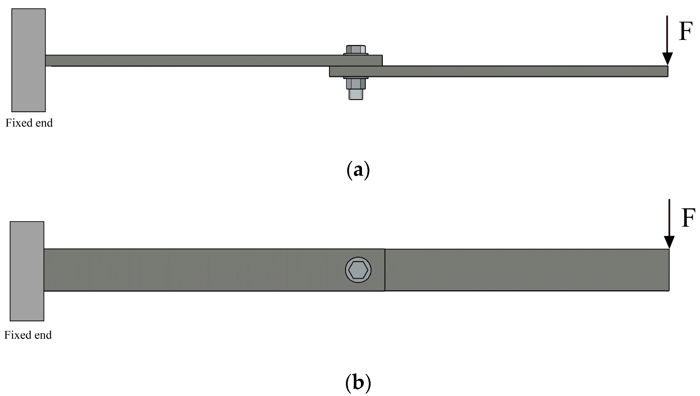
Figure 1. The cantilevered bolt-jointed beam. (a) The load is parallel to the bolt axis; (b) The load is perpendicular to the bolt axis.
Machines 11 00342 g001
Figure 2. Dimensions of the beam component (mm).
Machines 11 00342 g002
Figure 3. Equivalent dynamic model of the cantilevered bolt-jointed beam.
Machines 11 00342 g003
Figure 4. A typical hysteresis loop of the Valanis model.
Machines 11 00342 g004
Figure 5. Mesh of the equivalent model.
Machines 11 00342 g005
Figure 6. Reaction force–displacement curves of four solid FEM models with different mesh densities.
Machines 11 00342 g006
Figure 7. Mesh of the solid FEM model: (a) The mesh of the bolt-jointed beam; (b) The local mesh of the steel beams; (c) The mesh of the bolt, nut and spacers.
Machines 11 00342 g007
Figure 8. Normal pressure distribution: (a) On the contact surface between beams; (b) Section view on the contact surface between beams.
Machines 11 00342 g008
Figure 9. Strain in the transverse direction: (a) On the contact surface between beams; (b) Section view on the contact surface between beams.
Machines 11 00342 g009
Figure 10. The transverse displacement: (a) Overall bolt-jointed beam; (b) The beam with a fixed end; (c) The beam with a free end.
Machines 11 00342 g010
Figure 11. Reaction force–displacement curve under static transverse load.
Machines 11 00342 g011
Figure 12. Restoring moment—relative rotation curve of the joint under static transverse load.
Machines 11 00342 g012
Figure 13. Dynamic responses of the bonded Timoshenko beam model under harmonic excitation with different excitation amplitude: (a) F0 = 100 N (b) F0 = 200 N.
Machines 11 00342 g013
Figure 14. Dynamic responses of the bonded Timoshenko beam model under different time-step, F0 = 300 N, ω = 90 rad/s.
Machines 11 00342 g014
Figure 15. Hysteresis loops of the bolted joint under different excitation frequency: (a) ω = 30 rad/s; (b) ω = 50 rad/s; (c) ω = 70 rad/s; (d) ω = 90 rad/s.
Machines 11 00342 g015aMachines 11 00342 g015b
Figure 16. Energy dissipation per cycle.
Machines 11 00342 g016
Figure 17. Correlation coefficient Ce.
Machines 11 00342 g017
Figure 18. Responses of the equivalent model and the solid FEM model under different excitation frequency: (a) ω = 30 rad/s; (b) ω = 50 rad/s; (c) ω = 70 rad/s; (d) ω = 90 rad/s.
Machines 11 00342 g018aMachines 11 00342 g018b
Figure 19. Amplitude–frequency responses of the equivalent model and the solid FEM model.
Machines 11 00342 g019
Figure 20. Responses of the equivalent model and the solid FEM model under different preload levels, F0 = 500 N, ω = 30 rad/s.
Machines 11 00342 g020
Figure 21. Responses of the equivalent model and the solid FEM model under different preload levels, F0 = 500 N, ω = 30 rad/s.
Machines 11 00342 g021
Table 1. Definition of contact pairs.
Contact Surface
(CONTA174 Element)
Target Surface
(TARGE170 Element)
Number of Contact Pairs
Free beamFixed beam1
Head of bolt Washer1
beamsWasher1
NutWasher2
Bolt shankInner surface of the nut1
Bolt shankInner surfaces of washers2
Bolt shankBolt hole of beams2
Table 2. Parameters setting for the contact elements.
ParameterANSYS Real
Constant
DescriptionValue
knFKNNormal penalty stiffness factor1.61
kτFKTTangent penalty stiffness factor0.277
b(N)CHOEContact cohesion0
cDCExponential decay coefficient41,278
  μ d MUDynamic coefficient of friction0.183
μ s / μ d FACTStatic/dynamic ratio1.21
u m a x e (mm)SLTOAllowable elastic slip−1.7 × 10⁻⁵
Table 3. Analysis cases for each mesh density.
MeshNumber of ElementsNumber of NodesElapsed CPU Time (s)
Case 112011962816
Case 2235534241298
Case 3449461382280
Case 420,91026,7488719
Table 4. The parameters obtained from the fit used in the Valanis model.
Frequency (Rad/s)E0 (kNm/Rad)Et (kNm/Rad)σ0 (Nm)κ
3022.02.1571.10.3
5021.22.1174.70.2
7021.12.0273.60.2
9018.51.75770.1
Table 5. Steady-state response amplitude under different excitations.
Frequency
(Rad/s)
Applied Loads
(N)
Steady-State Response Amplitude (mm)
Solid FEM ModelEquivalent ModelError (%)
302402.822.80+0.71
2704.183.95−5.50
2854.844.72−2.48
3005.325.36+0.75
502402.942.94+0.01
2704.144.06−1.93
2855.155.26+2.14
3005.966.07+1.84
702403.153.22+2.22
2704.554.50−1.10
2855.665.63−0.53
3006.776.83+0.89
902403.773.78+0.27
2704.955.14+3.84
2856.276.16−1.75
3007.597.71+1.58
Disclaimer/Publisher’s Note: The statements, opinions and data contained in all publications are solely those of the individual author(s) and contributor(s) and not of MDPI and/or the editor(s). MDPI and/or the editor(s) disclaim responsibility for any injury to people or property resulting from any ideas, methods, instructions or products referred to in the content.