Lotfi A. Zadeh invented fuzzy logic in 1965 [
19]. It is a multivalued logic that allows the specification of intermediate values between conventional evaluations, such as true or false, or high or low. It provides a high degree of flexibility in reasoning, allowing for the absorption of errors and uncertainties. It is an appropriate method for fault diagnosis. Fundamental to fuzzy systems is the fuzzy set. In contrast to classical set theory, in which the membership of items in a set is evaluated in binary terms, fuzzy set theory permits the gradual evaluation of the membership of elements. A linguistic variable is one whose values are words or phrases in a natural or artificial language [
20]. The supplied mathematical values are transformed into fuzzy membership functions and linguistic variables. Then reverse defuzzification techniques can convert a fuzzy output membership function to a “sharp” output value that can be used for decision-making or control purposes.
2.1.1. Fuzzy Logic Diagnosis Algorithm for Exemplar Sensor System
In this section, the fault diagnosis algorithm for the exemplar sensor system was built using the fuzzy logic method. The six sensors and their four fault states (positive offset, negative offset, total loss, and outlier) were involved. Since the rule bases of Mamdani fuzzy inference systems are more intuitive and simpler to comprehend, the Mamdani system was utilized here for fault diagnosis. The fuzzy logic algorithm is divided into five steps: fuzzification of the input signals, application of the fuzzy operator in the antecedent, the implication from the antecedent to the consequent, aggregation of the consequents across the rules, and defuzzification which comprise the fuzzy inference process.
As the input of the fuzzy logic system, there are eight residual values, the difference between the sensor-measured data and model-estimated data:
(the residual of the steering wheel angle),
(the residual of the steering wheel torque),
(the residual of the yaw rate),
(the residual of the tie rod force),
(the residual of the left rear wheel speed with geometric model),
(the residual of the right rear wheel speed with geometric model),
(the residual of the left rear wheel speed with Kalman filter),
(the residual of the right rear wheel speed with kalman filter). For the specific calculation method, please refer to the authors’ above-mentioned paper [
18]. In the Mamdani fuzzy inference system, the first step is to transform the numerical value into a linguistic term and determine its degree of membership between 0 and 1. For example, three trapezoidal membership functions, “residual increase,” “residual zero,” and “residual decrease”, were applied here to fuzzify the input signals. Experimental results of the simulation chose the threshold for each function. After fuzzifying the inputs, the degree to which each antecedent component is satisfied for each rule was determined. The AND operator was utilized to obtain a single integer representing the result of the rule’s antecedent when the rule’s antecedent contains many components. In addition, the output signal’s membership function must be determined, and here four triangle membership functions were used, corresponding to the fault types “positive offset”, “non-fault”, “negative offset”, and “total loss”. They are used to convey the diagnostic outcomes for each sensor. Aggregation is the process of combining the fuzzy sets representing each rule’s outputs into a single fuzzy set. MAX was the aggregating method used in this paper. The aggregate output fuzzy set is the input for the defuzzification process, and the output is a single number. The chosen defuzzification method was the middle of maxima (MOM), namely, the middle of elements with maximum membership value. Each output signal from the defuzzification process indicates if a fault is present in the specific sensor. Furthermore, the type and the time-varying behavior can be determined through the waveform of the output signals.
Since there are four types of sensor faults and no faults are involved in the fault diagnosis of the sensor, the final output of the fuzzy logic is a definite number. Here, we determined that “1” represents “positive offset fault”, “−1” indicates “negative offset fault”, “−2” corresponds to “ total loss fault”, and “0” is “no-fault”. An outlier fault requires no special number because it can be judged from the resulting shape.
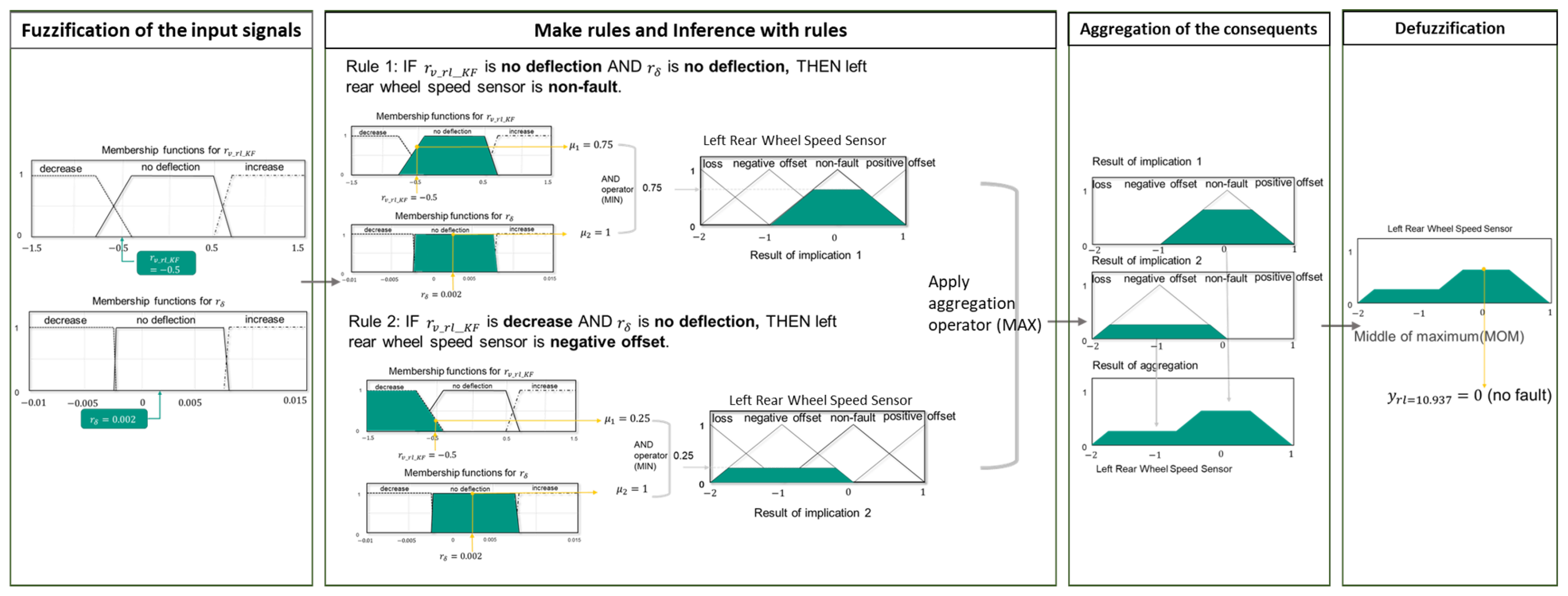
Here we use an example to illustrate the reasoning process of fuzzy logic more vividly. The entire reasoning process for this example is shown in
Figure 2. First, we get two residual values:
and
. For these two residuals, we first determined their membership functions with the help of the simulated data, which correspond to the two membership function diagrams in the leftmost box in
Figure 2. When their membership functions are determined, the following two rules are formulated for them:
Rule 1: If is no deflection AND is no deflection, THEN left rear wheel speed sensor is non-fault;
Rule 2: If is decrease AND is no deflection, THEN left rear wheel speed sensor is negative offset;
The inference results of the two rules can be seen in the second box in
Figure 2. It demonstrates that, by rule 1, the membership function corresponding to residual value
is 0.75, whereas the membership function corresponding to residual value
is 1. The outcome of applying the AND operator to the results of the two membership functions is then 0.75. According to this criterion, the probability that a sensor would not fail is 0.75. When matching to rule 2, the membership function for residual value
is 0.25, and the membership function for residual value
is 1. The outcome of applying the AND operator to the results of the two membership functions is 0.25. In other words, according to this criteria, the likelihood that the sensor has a negative deviation defect is 0.25. Merge the results of the two rules, and then use the MOM approach to defuzzify. The ultimate diagnosis result is 0, which indicates that the sensor is not defective.
2.1.2. Fuzzy Logic Diagnosis Algorithm for Exemplar Actuator System
In this chapter, we will introduce the fuzzy logic technique for actuator fault diagnosis. Two steering motors, two driving motors, and five states for each motor are included (no fault, small fault, middle fault, large fault, and total loss). The method of applying fuzzy logic enables the diagnostic to assess not only whether the system’s state is faulty but also the fault’s severity.
The fault diagnosis algorithm based on fuzzy logic techniques is the next step in model-based fault detection. It initially calculates the intended driving states using a mathematical model, including side-slip angle, yaw rate, target steering angle, target speed, etc. By comparing the ideal driving states to the actual driving states, which are measured by sensors, a set of residuals is calculated, which are the essential symptoms for fault diagnosis. The detailed process for calculating residuals is described in paper [
18]. The key discussion here is the content of the fault diagnosis after getting the fault symptoms. For actuators, developing a fuzzy diagnostic algorithm is the same as for sensors. The Mamdani inference is still used. The method for defuzzification is the center of gravity. It determines the data’s central position as the output result of the fuzzy system. This method can provide a more objective estimate of the fault’s severity by considering the general distribution of the data.
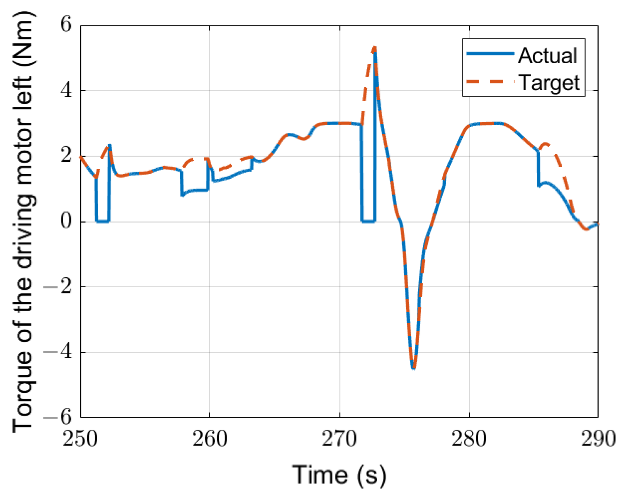
When diagnosing the steering system, the residuals we used include (the difference between the target yaw rate and actual yaw rate), (the difference between the target side slip angle and actual side slip angle), (the difference between the target steering angle and actual steering angle), (the difference between the target steering torque and actual steering torque of the steering motor 1), (the difference between the target steering torque and actual steering torque of the steering motor 2). The fault diagnosis algorithm for the two driving actuators is similar to that for the two steering motors. Here mostly two residuals are employed as the symptoms of the fault diagnosis for determining the driving motor’s fault severity: (the difference between the target speed and actual speed) and (the difference between the ideal tie rod force and the actual tie rod force). Among them, the speed residual is utilized to assess the presence of a fault, and the tie rod force residual is used to diagnose the severity of the motor fault.
2.1.3. Results of Fuzzy Logic Diagnosis Algorithm
- (1)
Case a: Results of Fuzzy Logic Diagnosis For Sensors
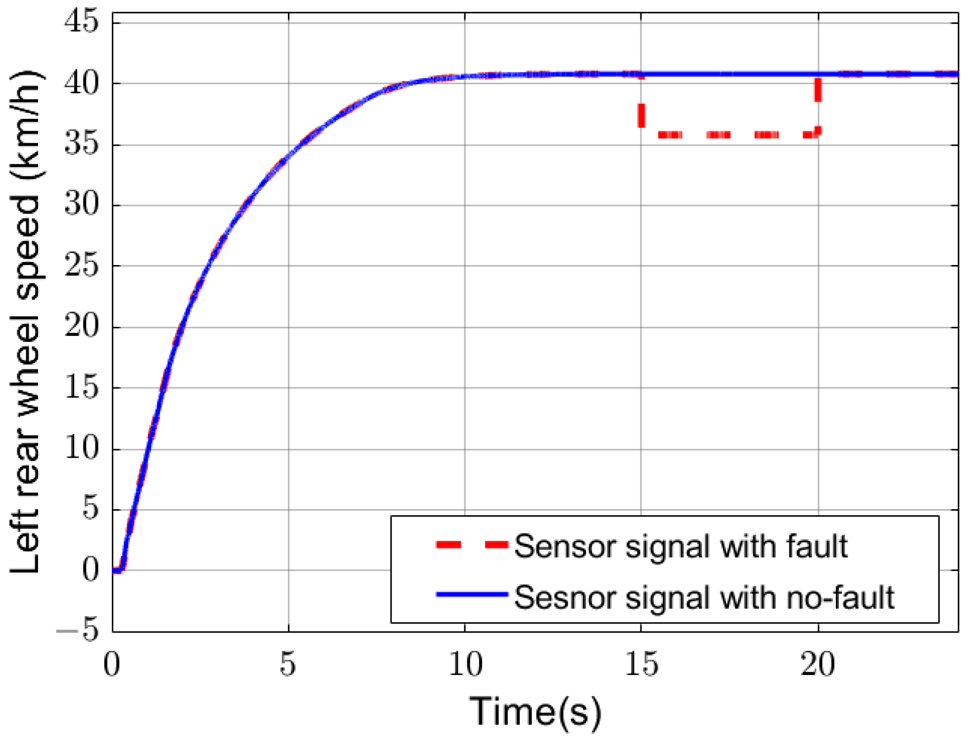
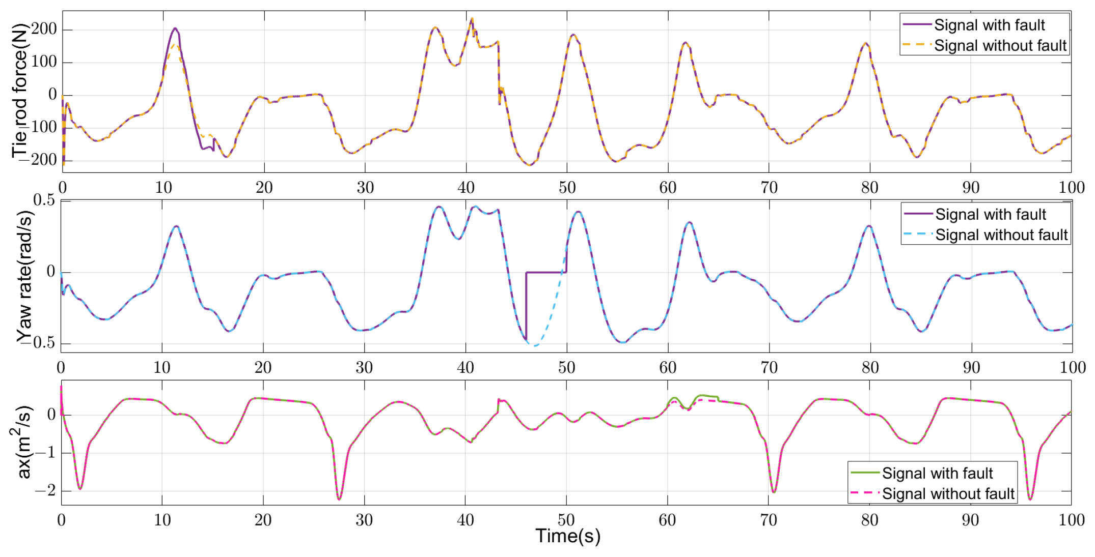
An example of sensor fault diagnosis results is shown in
Figure 3 and
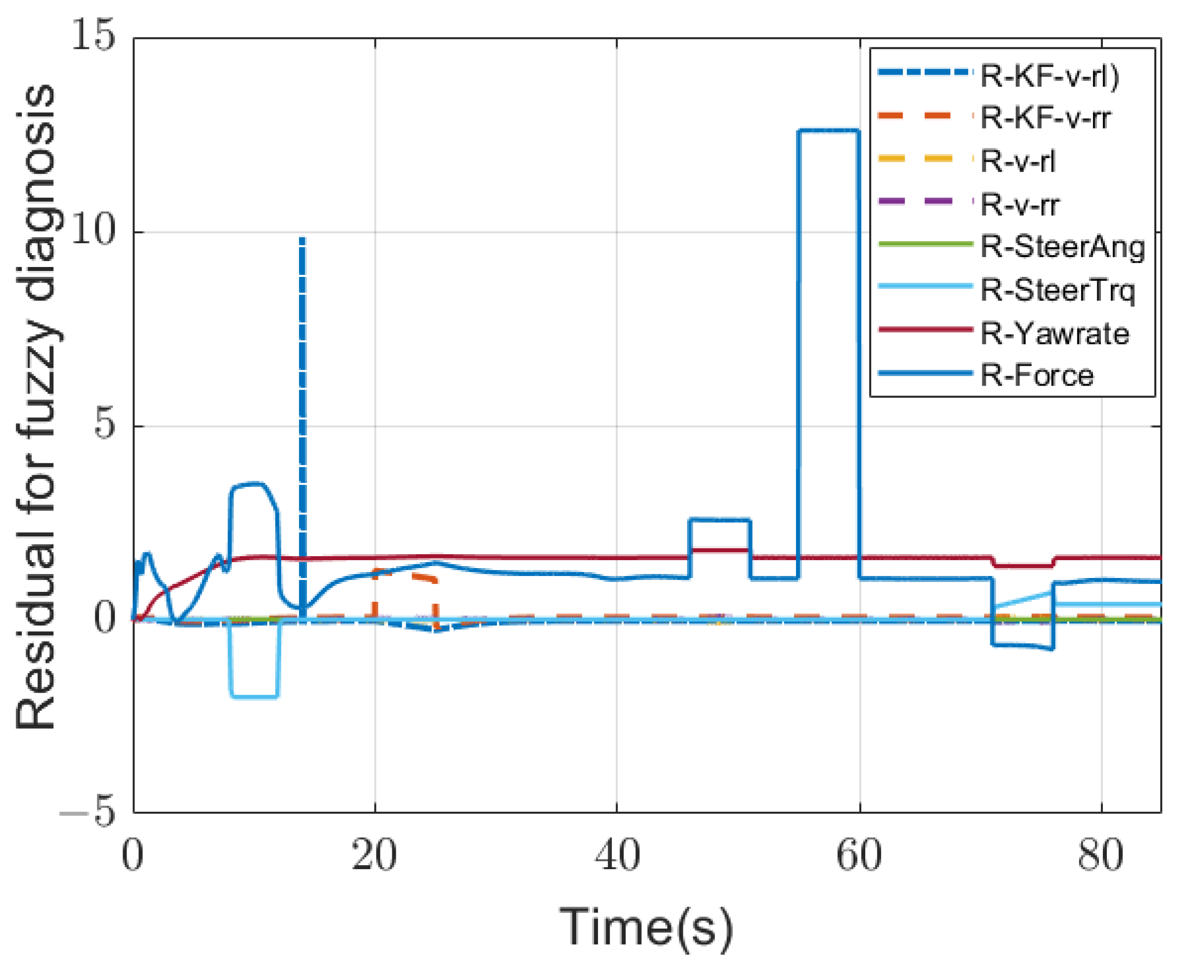
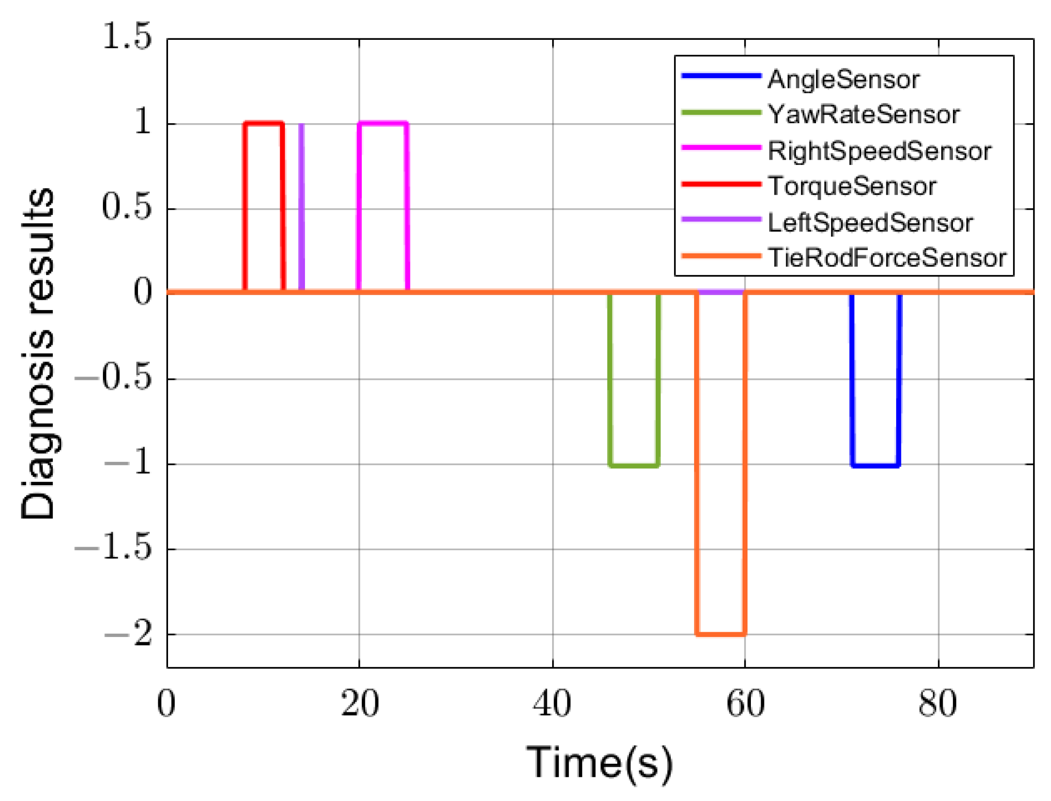
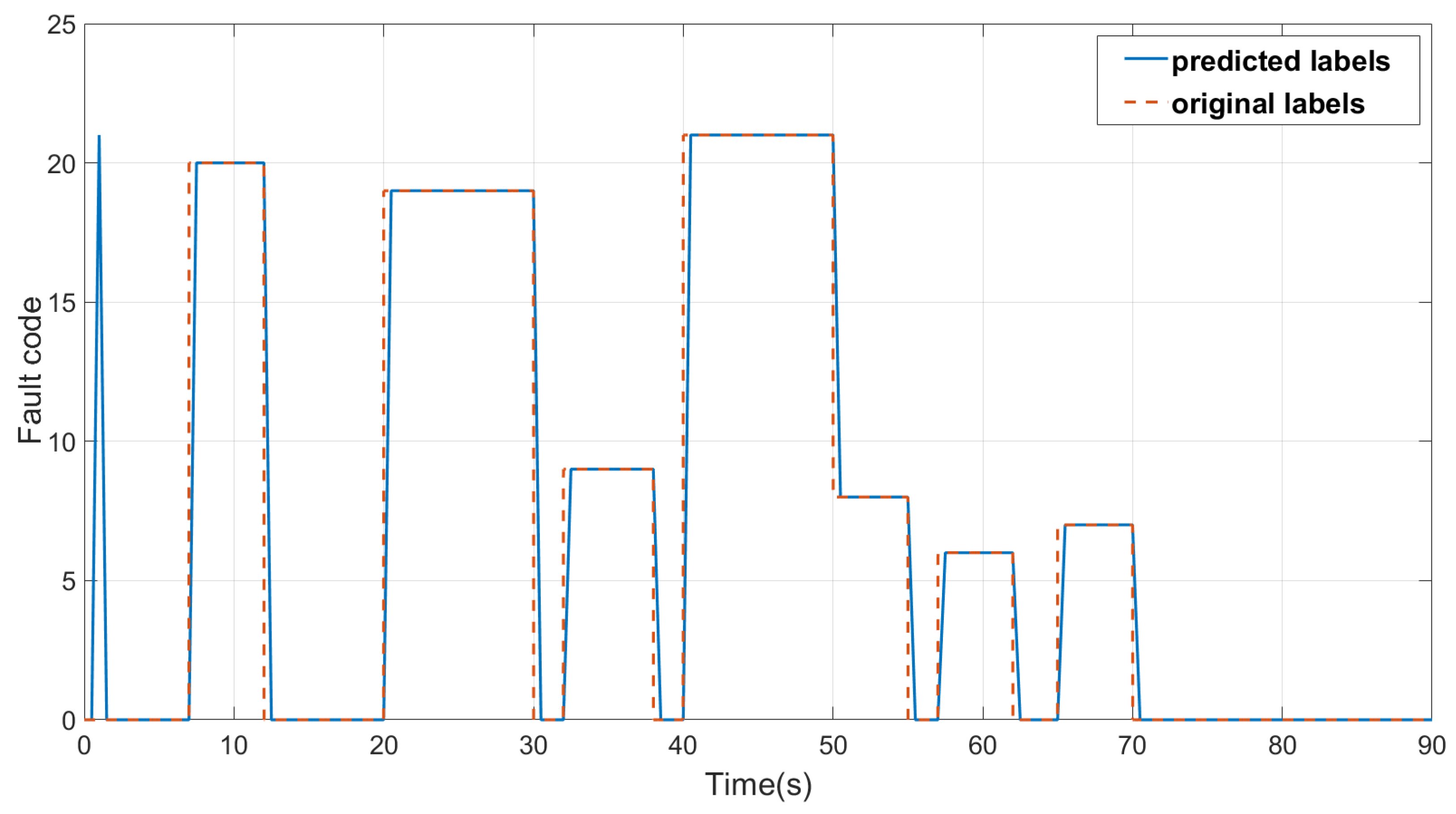
Figure 4. In this test, we used a steady circular test with a radius of 24 m, and a fault injected at each sensor. There is a positive offset fault (fault code +1) in the steering wheel torque sensor between 8 and 12 s, an outlier fault in the left wheel speed sensor that only lasted 0.001 s at 14 s, a positive offset fault in the right wheel speed sensor between 20 and 25 s, a negative offset fault (fault code −1) in the yaw rate sensor between 46 and 51 s and a total loss fault (fault code −2) in the tie rod force sensor between 55 and 60 s, a negative offset fault in the steering wheel angle sensor between 71 and 76 s.
Figure 3 shows the eight residual values used as inputs for fuzzy logic diagnosis, which have obvious changing trends within the corresponding fault injection periods. After the fuzzy logic diagnosis, we can get the six sensor diagnosis results, as shown in
Figure 4. In this test, the six faults in the six sensors can be detected very accurately.
- (2)
Case b: Results of Fuzzy Logic Diagnosis For Steering Actuators
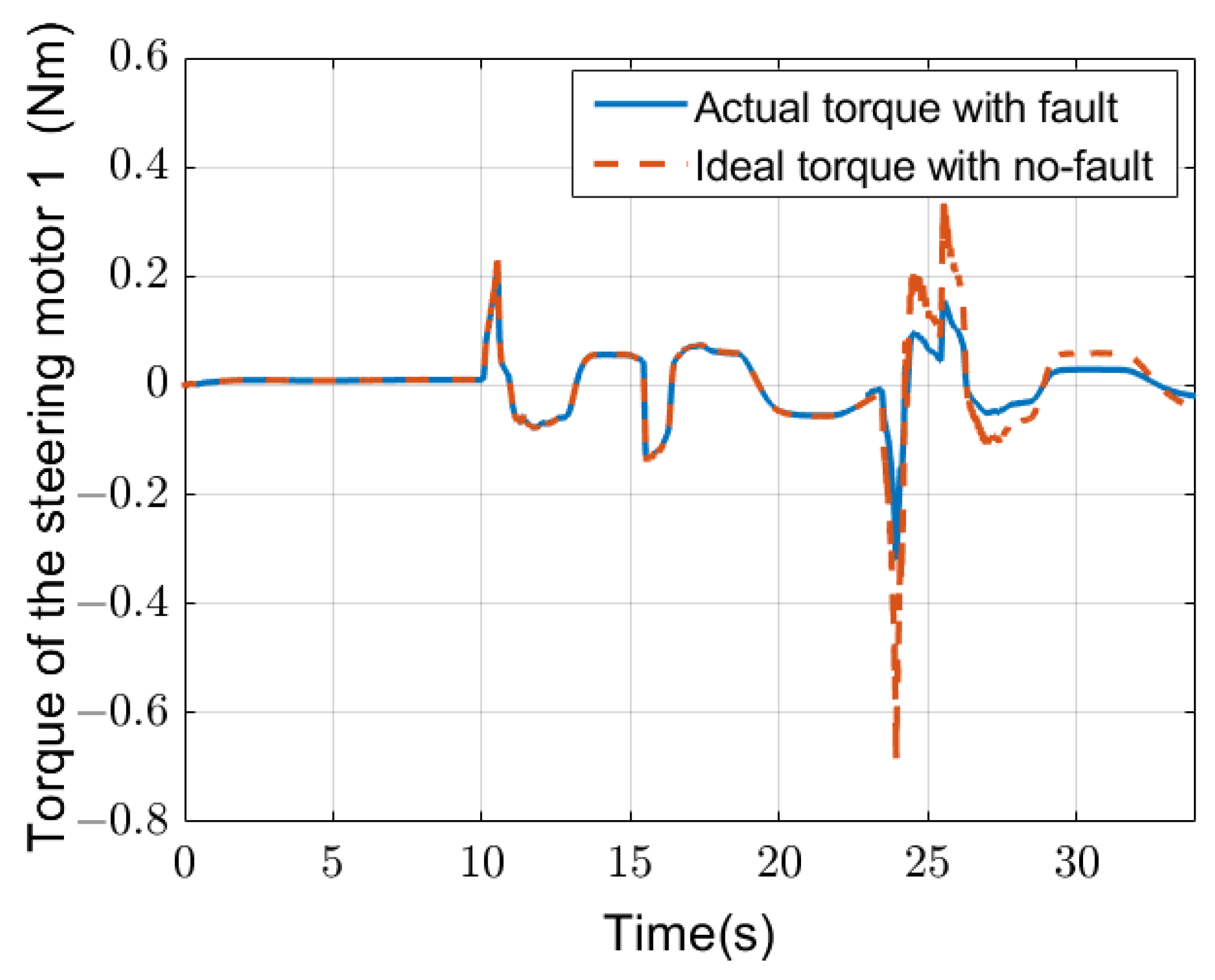
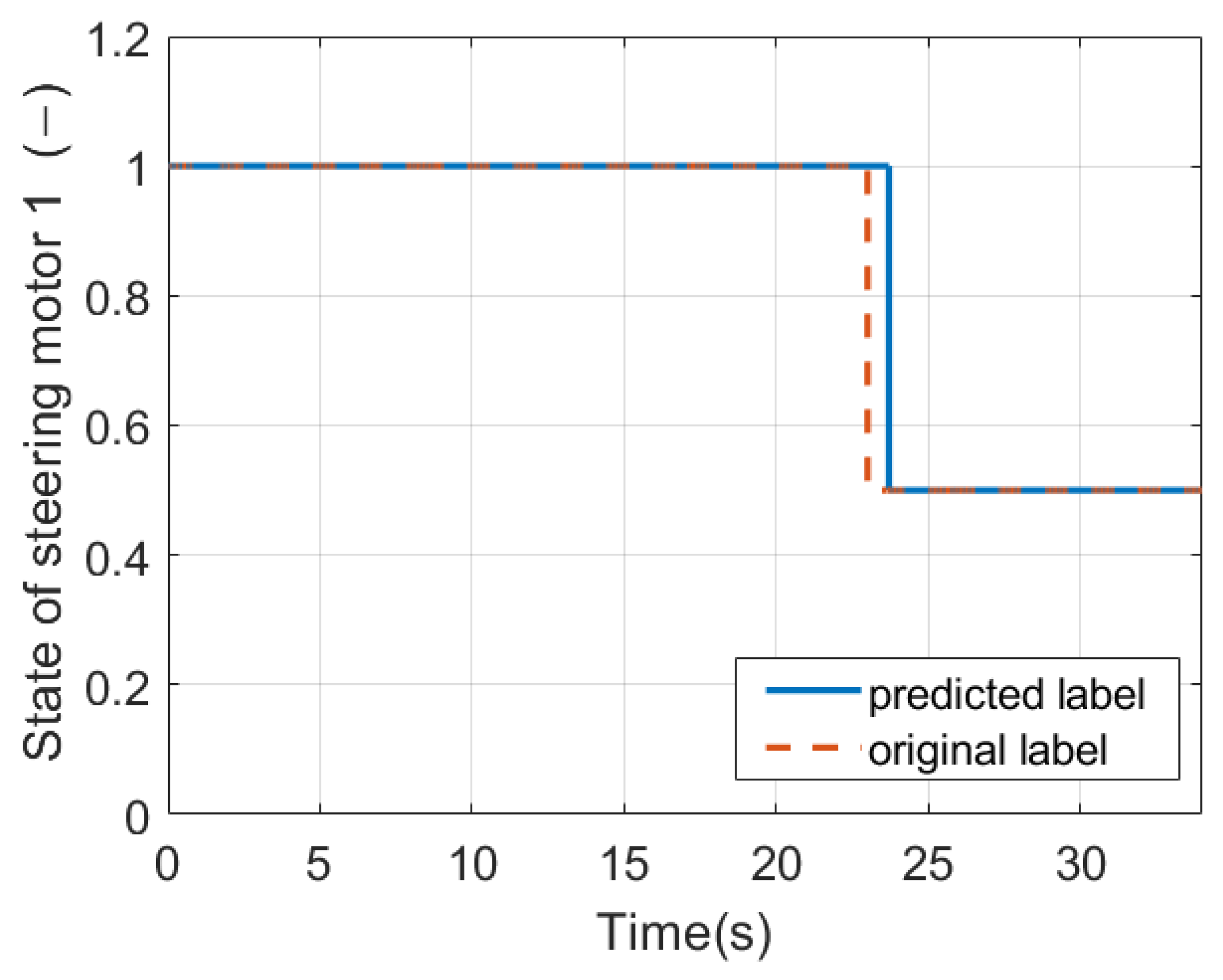
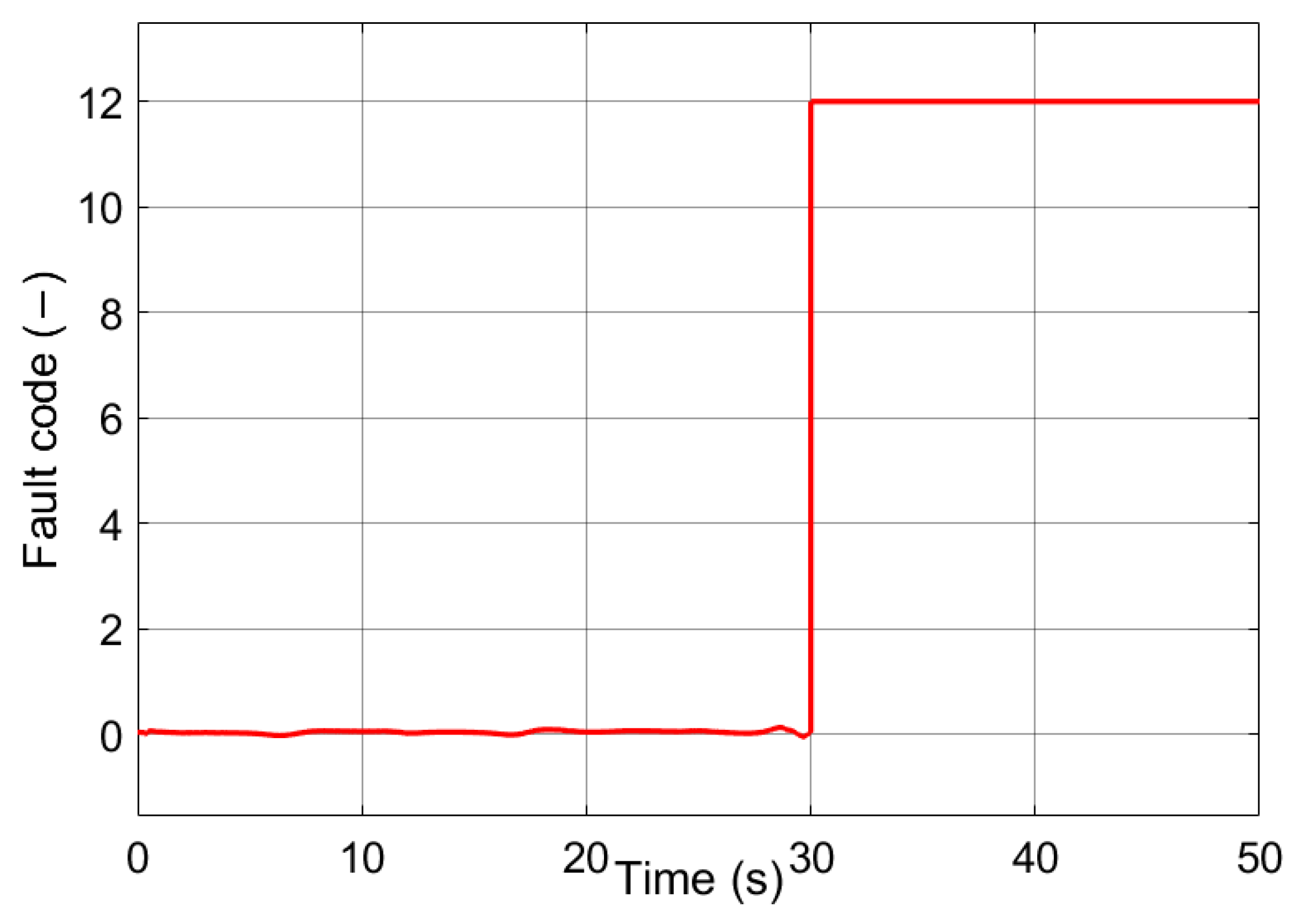
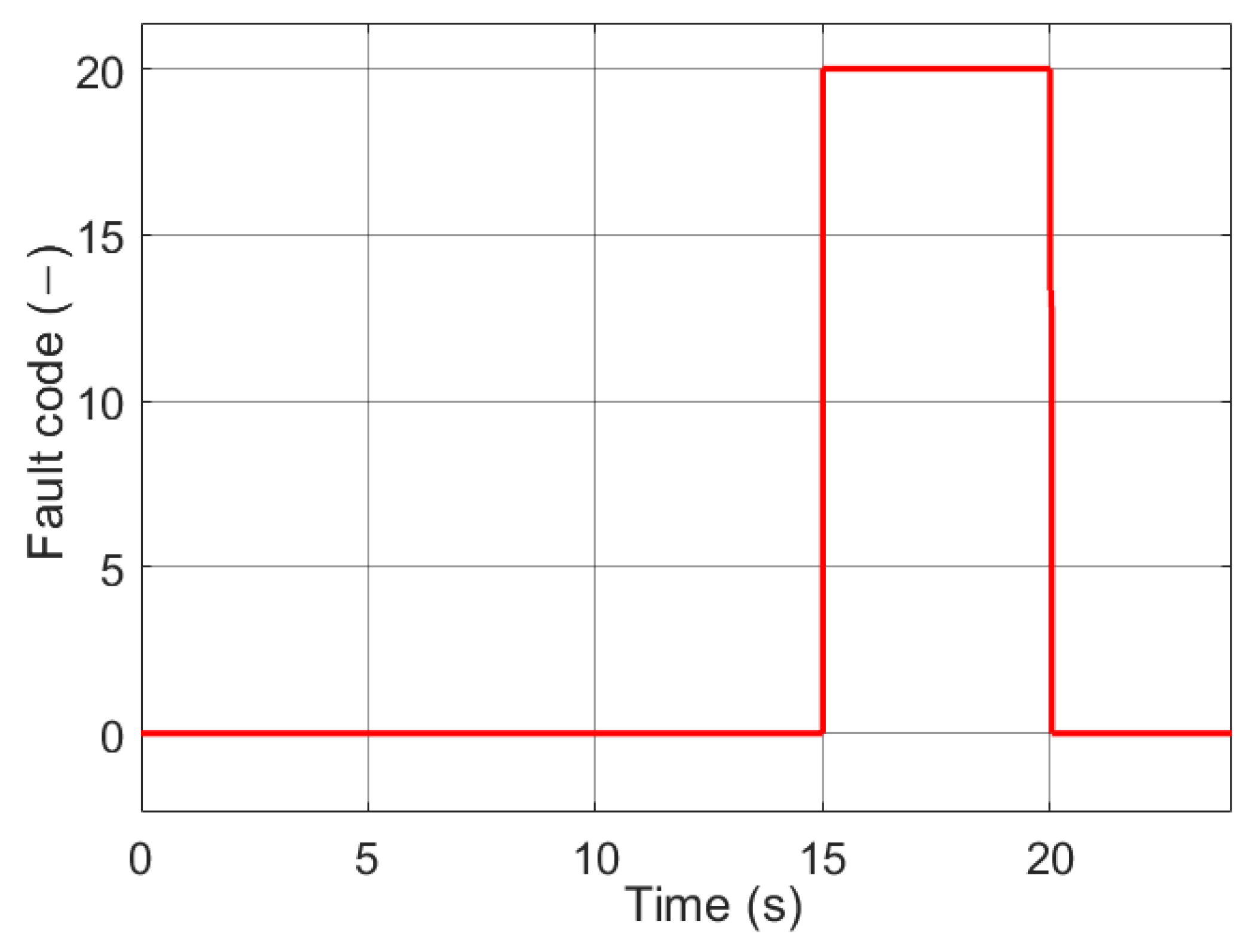
Figure 5 and
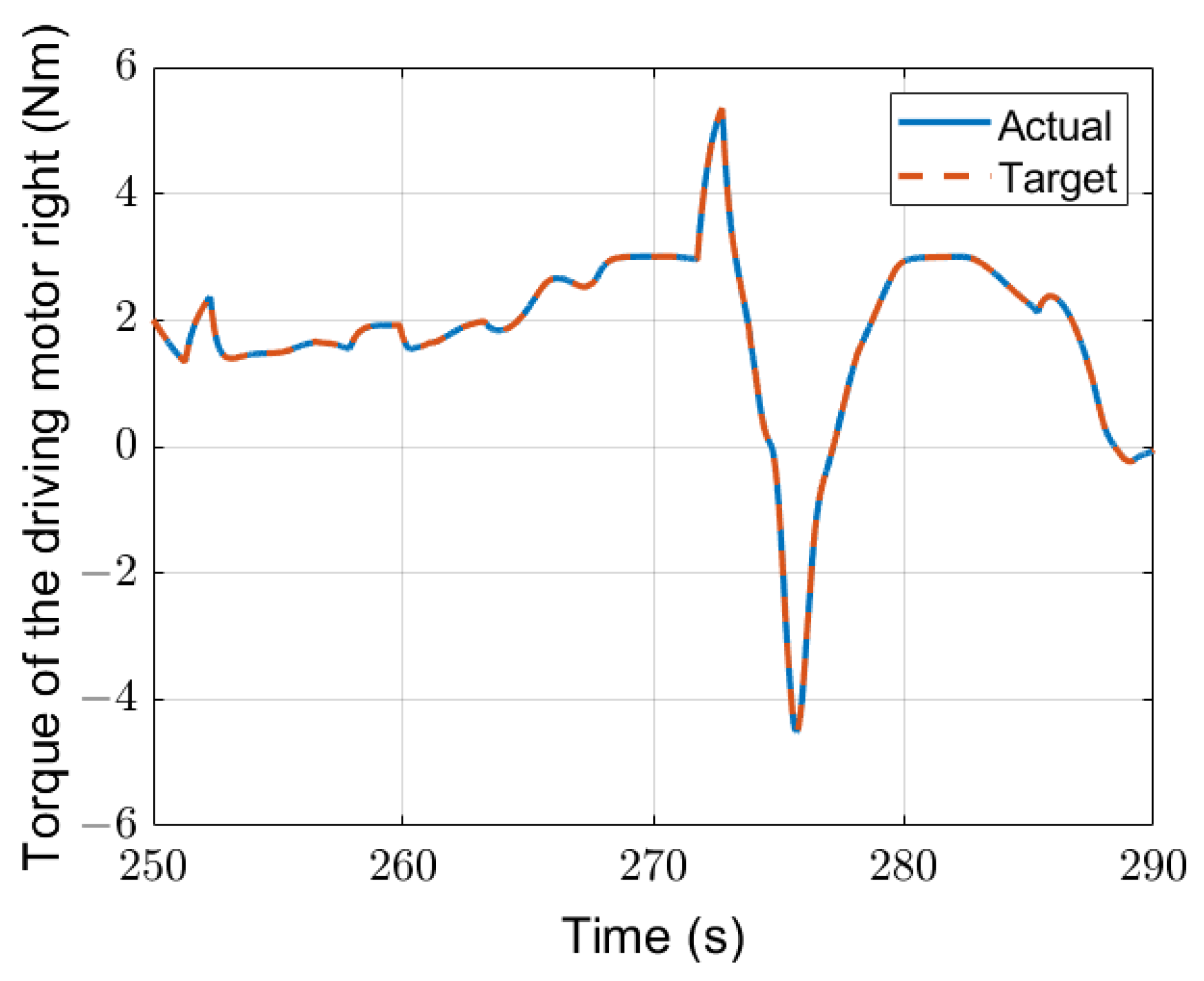
Figure 6 show an example of the diagnosis result of a double lane change test for evaluating the fault diagnosis for actuators. The test vehicle is driven on the road at its maximum speed of 20 km/h for 34 s. There is a fault beginning at the 23 s that lasted until the end. The fault injected here is a Middle-Fault (50% target torque can be output). In this test, only steering motor 1 is operational.
Figure 5 depicts the difference between the ideal torque and the actual output torque beginning at 23 s when the steering motor fails and cannot produce the needed torque.
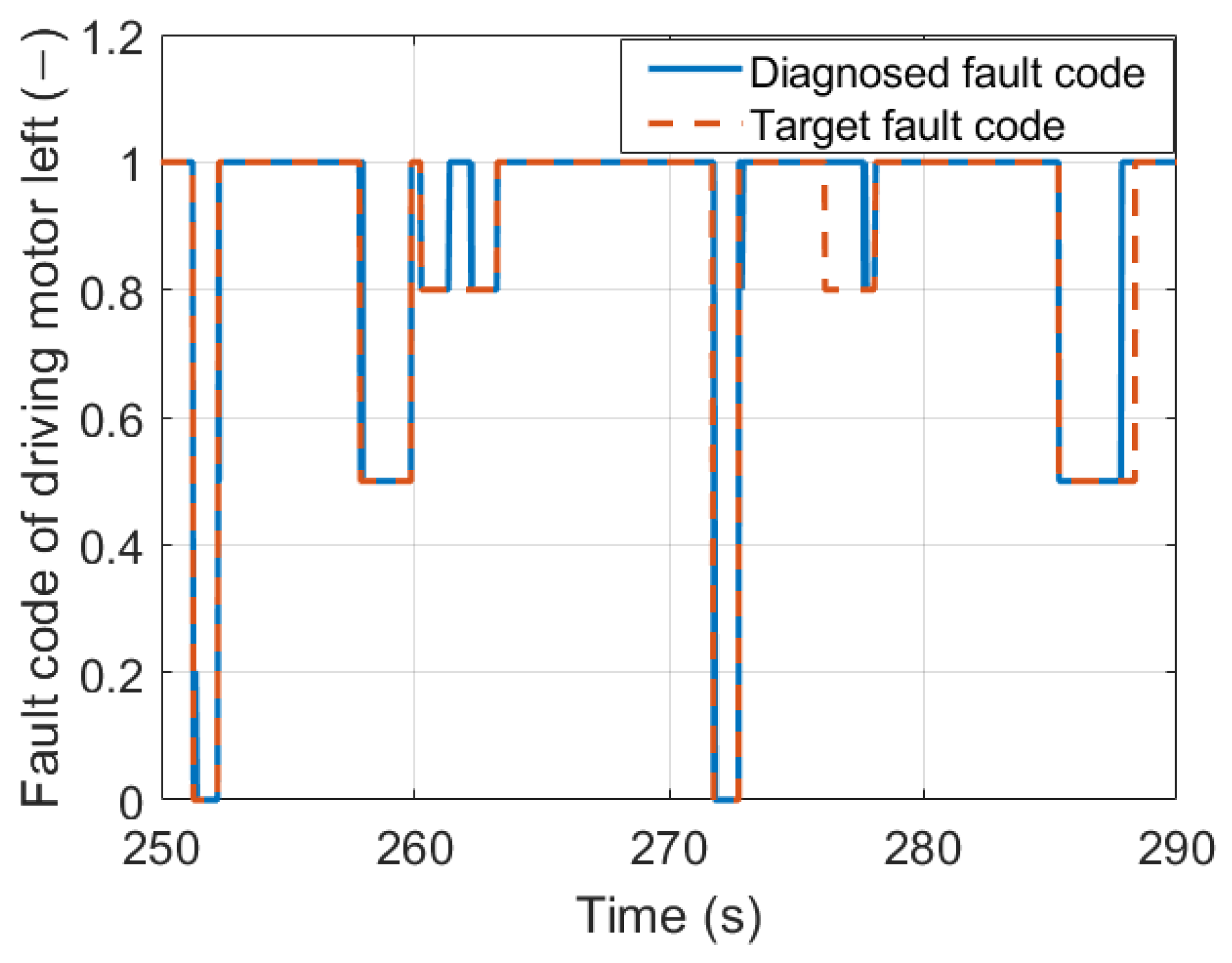
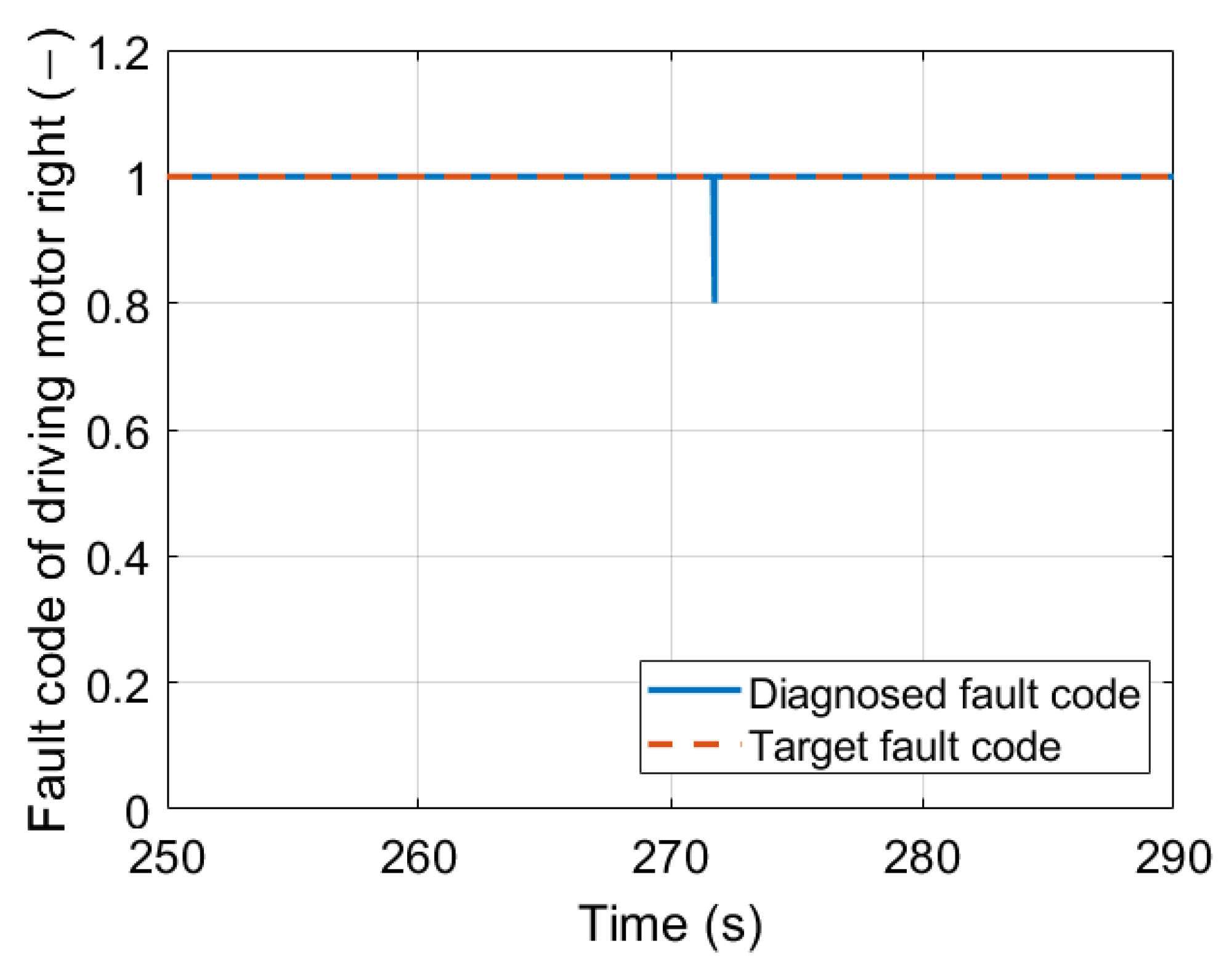
Figure 6 depicts the result of the fuzzy logic fault diagnosis (blue line). 1 indicates that the motor is operating normally. At 23.6 s the diagnosis result changes to
until the end, indicating that the present motor has a malfunction of medium severity. The fault occurred at 23 s. However, the faulty diagnosis was delayed by approximately 0.6 s. This is because, at 23 s, the anticipated steering torque is quite small. Even if a fault occurred, the resulting vehicle dynamic deviation is within the permitted range, diagnostics considered the actuator in a no-fault state.
The fault diagnosis algorithm based on fuzzy logic developed here can establish the fault’s type, location, and time-varying behavior if present in any of the sensors and actuators. This approach uses the generated residuals by mathematical models of the vehicle as its foundation. In response to modifying symptom vectors, a fuzzy logic system was implemented for fault diagnostics. The fuzzy logic outputs showed the type, location, and time-varying behavior of a defect. This method is very effective in diagnosing the fault state of a single sensor and the actuator fault severity.


