Abstract
The development of high-performance mass spectrometer and vacuum coating technology has placed higher demand on the vacuum level of turbomolecular pumps (TMPs), which are required to possess a greater compression ratio and faster pumping speed. There exists a relation of “as one falls, another rises” between the compression ratio and the pumping speed when traditional improvement methods are used. How to simultaneously increase the compression ratio and pumping speed is a very important question for the high-end turbomolecular pumps. In this study, on the basis of a parallel blade and thin gas aerodynamic model, several types of curved blade are presented to improve the pumping performance of TMPs. The comparison results show that the positive quadratic surface exhibited a better pumping performance than the other curved blades. After that, a hybrid optimization method based on a support vector machine (SVR) and particle swarm optimization (PSO) are proposed to obtain the structural parameters of the rotor blade for the highest pumping speed and maximum compression ratio. The optimization results show that, compared with the parallel blades, the compression single-stage blade row with quadratic surface structure was able to increase the maximum compression ratio by 10.35% and the maximum pumping speed factor by 4.61%. In addition, the intermediate single-stage blade row with quadratic surface structure increased the maximum compression ratio by 9.15% and the maximum pumping speed factor by 2.53%.
1. Introduction
Turbomolecular pumps are widely used in many fields, such as semiconductor manufacturing, the etching process, and mass spectrometer and high-energy physics applications, which need clean high vacuum and ultra-high vacuum conditions [1,2,3,4]. Turbomolecular pumps have a multi-stage cross arrangement of the rotors and stators, which relies on high-speed rotating blades to achieve momentum transmission, and its performance indices are mainly the maximum compression ratio and the maximum pumping speed. The development of mass spectrometers and vacuum coating technology has placed higher demands on the vacuum levels of turbomolecular pumps [5,6], which require higher compression ratios and higher pumping speeds. In recent years, the optimization of the control strategy, the study of the modal analysis and critical speed, the reduction in impeller noise and vibration through the study of cavitation dynamics, and the improvement of the rotor strength have allowed the turbomolecular pump to achieve higher and higher speeds [7,8,9,10,11,12], and its pumping performance has also been correspondingly improved. The new molecular pumps being developed are constantly moving towards an ultra-high vacuum field [13]. However, as the speed increases, the rate of increase in the maximum compression ratio of the TMP will gradually slow down [14]. Thus, it important to study how optimizing the blade structure improved the pumping performance of TMP, which could lead to the development of molecular pumps that can achieve higher vacuums in the future. The research methodology can also be utilized to develop new molecular pumps with different pumping performance requirements.
Among the structural parameters of the blade, the factors with great impacts on the pumping performance of the turbomolecular pump are mainly the inclination angle and the chord ratio. With these two parameters, it is often difficult to achieve a good balance between the compression ratio and the pumping speed. For example, reducing the inclination of the leaf column will allow for a high compression ratio, but will reduce the pumping speed [15]. Sheng et al. [16] have shown that the increase in the chord ratio causes the maximum compression ratio to decrease rapidly, while the maximum pumping speed increases significantly. Therefore, it may be difficult to achieve the goal of increasing the compression ratio and the pumping speed at the same time by optimizing the two parameters of inclination and chordal ratio.
In view of the aforementioned problem of the structural optimization of turbomolecular pumps, domestic and foreign scholars have carried out a large number of research studies. Turbomolecular pumps typically operate at low pressures, where the flow state of the gas is a free molecular state that cannot be studied using the continuous media-based Navier–Stokes and Euler equations [17]. To calculate the pumping performance of the molecular pumps, a random molecular method known as Monte Carlo was developed to study the flow of thin gases in molecular pumps, and has been widely used in recent years for the study of molecular pumps. The Monte Carlo method can be divided into the direct simulation Monte Carlo method (DSMC) and the test particle Monte Carlo method (TPMC).
TPMC does not consider intermolecular collisions, and uses calculations to simulate gas flow [18]. When the state of a gas molecule is close to the transition flow, the Monte Carlo method (DSMC), which considers collisions between molecules, will be more suitable for simulating the flow of molecules. Versluis et al. [19] proposed a modeling method for moving blades and used the direct simulation Monte Carlo method to study the gas flow of molecular pumps in both free molecular flow and excessive flow. They obtained detailed information on the change of the molecular state in the system over time, which was able to determine various macroscopic parameters with results that were in good agreement with the experimental data. Sengil et al. [20] used an improved direct simulation Monte Carlo solver to simulate the pumping performance of the single-stage surface rotor, and the results showed that the Monte Calo method was able to simulate the pumping performance of the surface blade rows well.
However, in recent years, with the increase in molecular pump speed, the air flow in the blade rows is expected to approach the free molecular flow soon after the molecular pump reaches a stable speed, and TPMC, without considering the intermolecular collision, will be more suitable for the simulation calculation of the performance of the molecular pump. Mehrzad et al. [21] used the test particle Monte Carlo method to compare the pumping performance of wedge-shaped vanes and parallel vanes, and the results showed that the TPMC had high accuracy and that the pump speeds of high vanes at positive wedge angles were improved relative to those of parallel vanes. In the range of free molecular flow, Sun et al. [22], based on the experimental particle Monte Carlo method, wrote a custom program to simulate the flow state of gas molecules in a turbomolecular pump, then used another program to verify the rationality and accuracy of the calculation results of the method.
In terms of non-parallel blade rows, Bird [23] studied the pumping performance of the triangular cross-section blades using the direct simulation Monte Carlo method, and the results showed that in the free molecular flow stage, the front blades would effectively increase the maximum compression ratio if they had sharp leading edges. Sengil [24] compared the pumping performance of several curved blades and parallel blades in different flow fields using the direct simulation Monte Carlo method, and the results showed that the performance of the combination of the rotor that used the parallel blade and the stator that used the curved blade was expected to be better than the combination of the rotor and stator that both used the parallel blade.
In terms of model building, Yanwu Li et al. [25] studied the accuracy of three simulation models at different speed ratios within the range of free molecular flow, and the results showed that the simplified three-dimensional model was more capable of replacing the complex three-dimensional model than the two-dimensional model.
Based on previous research, this study adopted a simplified three-dimensional model to establish a thin gas dynamic simulation model of the single-stage blade row of a turbomolecular pump using the experimental particle Monte Carlo method. The accuracy of the simulation model was verified by comparing the results with the experimental data. Compared with the parallel blade row, a set of blade structure parameter simulation was carried out to analyze the influence of surface blade row parameters on pumping performance. On this basis, the blade structural parameters of quadratic surface blades were optimized by support vector machine regression (SVR) and particle swarm (PSO) multi-objective optimization algorithms, with maximum pumping speed and maximum compression ratio as the optimization goals.
2. Theoretical Model
2.1. Working Principle of Turbomolecular Pump
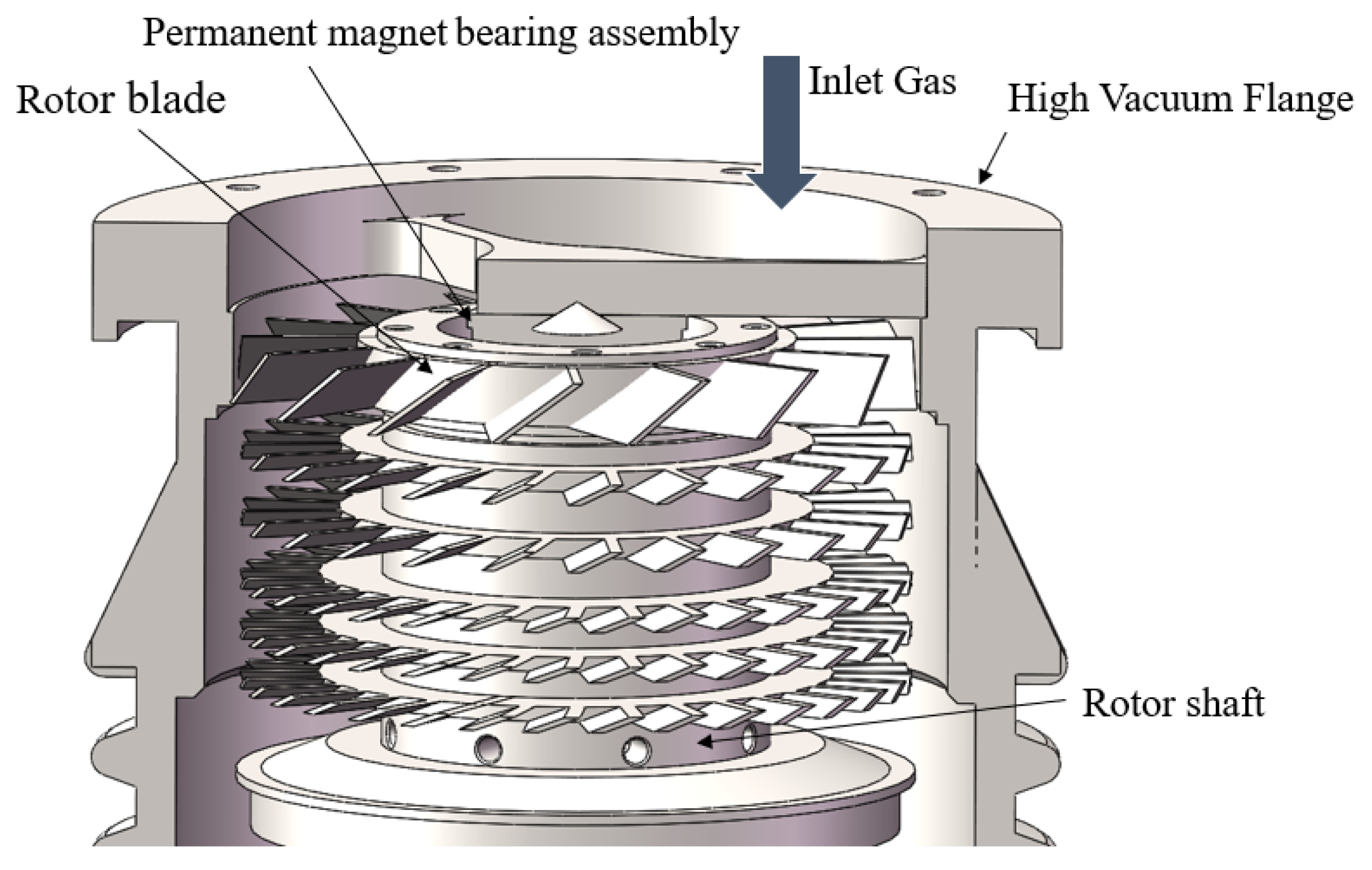
As part of the composite molecular pump, the working structure diagram of TMP is shown in Figure 1. The main working parts are the composite rotor, stator, and spindle assembly, in which the angle of the stator is opposite to the rotor and the rotor and stator are alternately arranged. The spindle drives the rotor rotation so that the probability of gas molecules on both sides of the blade row rotating at high speeds is different, forming a macroscopic pumping performance. The stator assembly is fixed to the pump housing, and due to the presence of rotors rotating at high speeds on both sides, the stator also has the same pumping effect as the rotor. The gas is transferred from the inlet to the outlet, and the outlet is connected to the inlet of the traction pump in the composite pump.
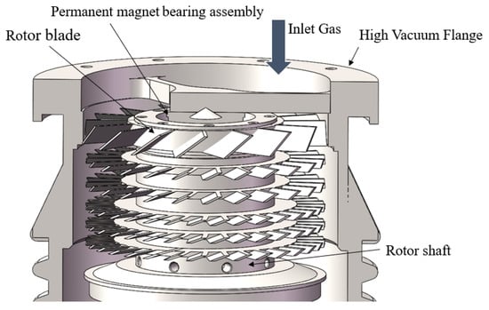
Figure 1.
Turbomolecular pump structure diagram.
2.2. Aerodynamic Modeling of Turbomolecular Pump
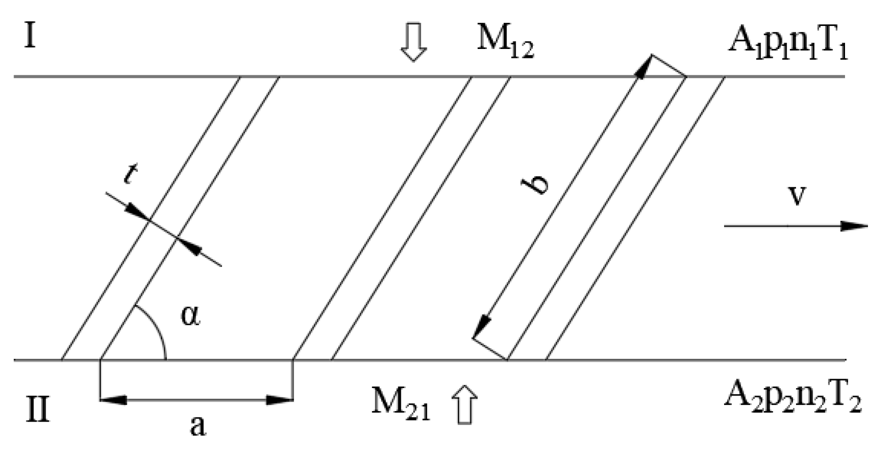
To study the performance of the turbomolecular pump, it is necessary to first study the pumping performance of the single-stage blade row. The structure of the single-stage blade row of the molecular pump is shown in Figure 2. R is the outer diameter of the blade, l is the length of the blade, and h is the height of the blade. The unfolded diagram of the single-stage blade row of the molecular pump is shown in Figure 3, where b is the blade chord length, t is the blade thickness, and α is the blade angle. On the I side, the pressure is p1, the molecular density is n1, the gas temperature is T1, and the total area of the channel port is A1. On the II side, the corresponding pressure is p2, the molecular density is n2, the gas temperature is T2, the total area of the channel port is A2, the blade row speed is v, and the blade spacing is a. The probability of gas molecules passing from upstream (I side in Figure 3) to downstream (II side in Figure 3) is the positive transmission probability M12, and the probability of gas molecules passing from downstream (II side in Figure 3) to upstream (I side in Figure 3) is the reverse transmission probability M21. It is the difference between the positive transmission probability and the reverse transmission probability that reflects the macroscopic pumping efficiency of the TMP.

Figure 2.
Structure diagram of the single-stage blade row of TMP.

Figure 3.
Expended view of the single-stage blade row of TMP.
The net gas flow of the gas molecules from the I side to the II side is:
If A1 = A2, T1 = T2, and p1/p2 = n1/n2, Formula (1) can be written as:
According to Formula (2), when p1 = p2, the maximum pumping factor Hmax can be obtained:
The maximum pumping Smax can be obtained by Formula (4):
In Formula (4), F is the effective channel area.
When H takes zero, that is, when the net air flow is zero, the maximum compression ratio Kmax can be obtained:
When the pumping speed is zero, the maximum compression ratio can be obtained; when the maximum compression ratio takes zero, the pumping speed can be obtained [26].
Generally, when calculating the pumping performance of the multistage blade row, we deem that it can be calculated on the basis of the transmission probability of the single-stage blade row [25]. The method used for calculating the maximum compression ratio and the pumping speed of the multistage blade row is as follows:
In Formula (6), Kn is the maximum compression of n-stage combined blade rows, Ki is the maximum compression of the i-stage blade row. In Formula (7), Hn is the pumping speed factor of n-stage combined blade rows, F is the effective channel area of the working blade row, M is the molecular weight of the pumped gas, and T is the ambient temperature. The pumping speed factor of the n-stage combined blade rows is given by Formula (8).
In Formula (8), M1n is the positive transmission probability of the n-stage combined blade rows, and Mn1 is the reverse transmission probability of the n-stage combined blade rows. The calculation formulae of M1n and Mn1 are given by Formulae (9) and (10):
As can be seen from the above equation, the pumping performance of the turbomolecular pump is related to the forward and reverse transmission probabilities M12 and M21 of the single-stage blade row at various levels, which mainly depend on the blade angle α, the pitch chord ratio a/b, and the ratio of the circumferential velocity of the rotor to the maximum velocity of the thermal motion of gas molecules C. The transmission probability of the single-stage blade row can generally be obtained by the integral equation method, the Monte Carlo method, and the transmission matrix method [15].
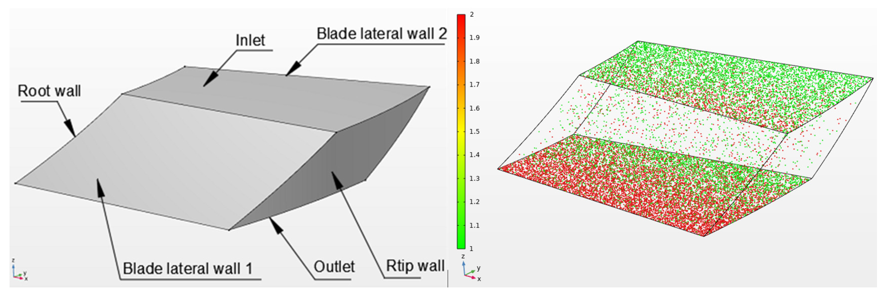
In this paper, the test particle Monte Carlo method was used to calculate the transmission probability of a single-stage TMP under different structural parameters by means of pumping simulation. Because the calculation domains are consistent between each of the two blades, only one of the calculation domains needs to be computationally simulated. The schematic diagram of the blade channels and their solutions for the single-stage TMP are shown in Figure 4. Especially, the Tip wall is the boundary of the wall of the TMP rather than the tip circle of the blade row. According to the DN-63 TMP provided by this project, the initial geometric parameter data of this study are shown in Table 1, and the operating parameters are the rotor speed n = 60,000 r/min, the molecular weight of the pumped gas M = 28 g/mol, and ambient temperature T = 300 K.

Figure 4.
Blade passage model and solution diagram of a single-stage blade row.

Table 1.
Initial geometric parameters of rotor blade rows.
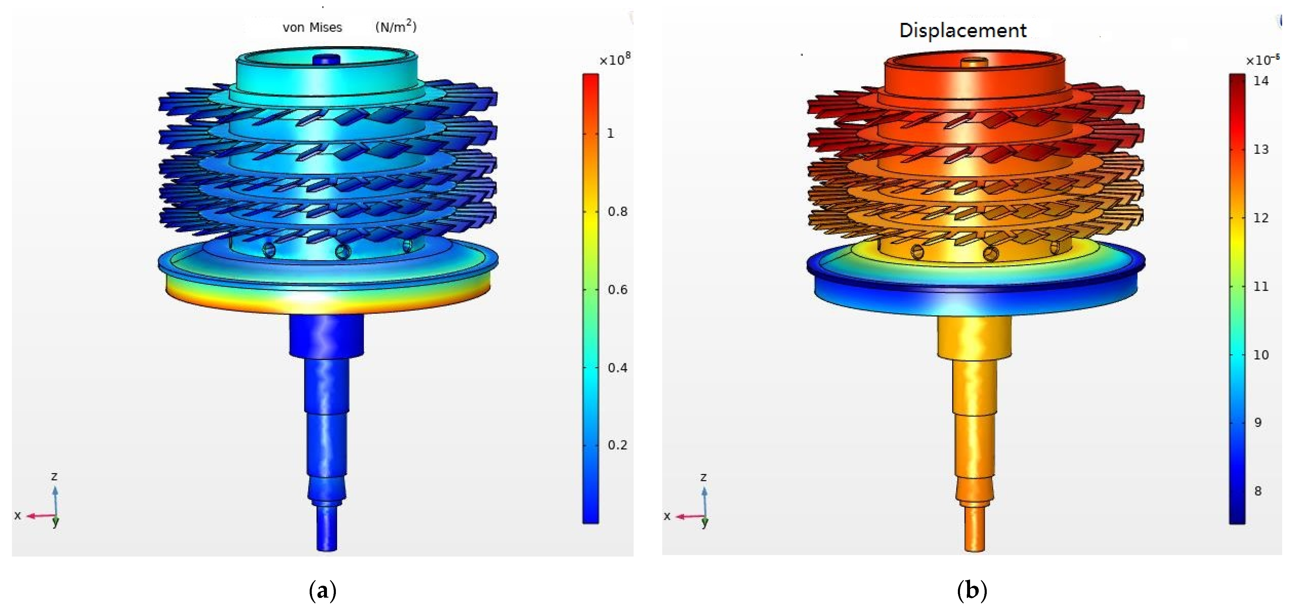
Firstly, the von Mises stress and deformation distribution of the flexible rotor under high-speed operation were studied. Due to the action of the backing pump and the traction stage, in which the turbine stage blade started to operate, the vacuum degree decreased rapidly, and the surrounding air entered the free molecular flow field, which was too weak to solve by computational fluid dynamics. The deformation of the rotor mainly came from the rotational force and vibration. In the case of favorable anti-vibration measures, only considering the influence of rotation and gravity, the solid rotor module in the COMSOL platform and the radial deep groove ball-bearing support model were used to analyze the stress and deformation of the blade. The material of the rotor was aluminum alloy 6061-T6. As shown in Figure 5, the maximum deformation of the blade was at the end, at 0.14 mm. Compared with the 67 mm diameter of the blade, this blade deformation can be ignored when calculating the pumping performance.
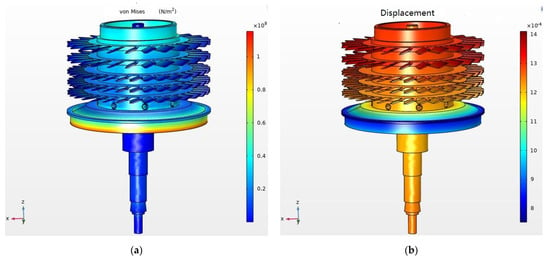
Figure 5.
Von Mises stress and deformation distribution of the rotor. (a) Von Mises stress; (b) deformation distribution.
3. Structure Design of a Single-Stage Blade Row with a Curved Surface
3.1. Design of Blade Row Structure
In parallel blade rows, both the positive transmission probability M12 and reverse transmission probability M21 increase with the increase in blade angle α, which enables the pumping speed factor to increase and the maximum compression ratio to decrease. If the non-parallel blade row can be designed so that the blade angle near the upstream inlet is different from the blade angle near the downstream inlet, it becomes possible to exert a distinct degree of influence on M12 and M21 and to improve the pumping speed and maximum compression ratio at the same time.
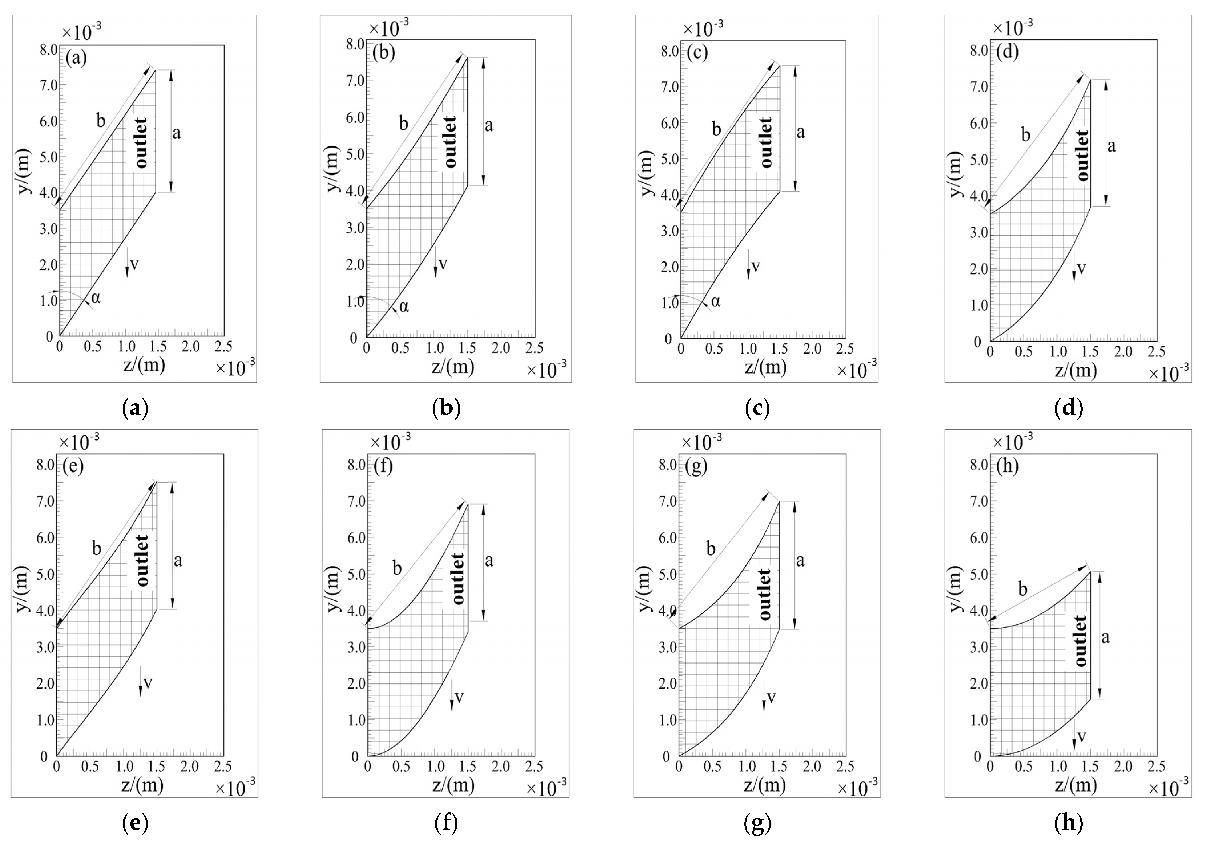
Firstly, we chose some common surfaces, such as quadratic, cubic, and parabolic surfaces; defined their parameters arbitrarily; and calculated their average angles using Formula (11). In order to better compare with the parallel blade row, for which α = 20°, we used the enumeration method to screen out the cross-section equations with an average angle close to 20° and good performance. Thus, seven different rotor models of non-parallel blades and of parallel blades were formed first in order to carry out the study and to improve the pumping performance of the compression stage blade row, as shown in Table 1. The eight blade models are exhibited in Figure 6, namely, parallel, quadratic surface, elliptical surface, cubic surface I, cubic surface II, exponential surface, and hyperbola surface. The quadratic surface blade models were divided into groups of those with positive quadratic surfaces and those with reverse quadratic surfaces according to the direction of bending, while the cubic surface blade models were divided into I and II according to whether the linear coefficient was zero or not. In Figure 6, v represents the rotation direction of the rotor, and the grid area represents the effective working region. “y/(m)” and “z/(m)” refer to the two axes of the blade clearance in three-dimensional space, according to Figure 4. The cross-sectional equations of the rotor models are listed in Table 2. The calculation method of the average angle is given by Formula (11):

Figure 6.
Cross-sections of blades of different shapes. b is the blade chord length, a is the blade spacing. (a) Parallel blade; (b) positive quadratic surfaces blade; (c) reverse quadratic surfaces blade; (d) elliptical surface blade; (e) cubic surface I blade; (f) cubic surface II blade; (g) exponential surface blade; (h) hyperbola surface blade.

Table 2.
Section equations of blades with different shapes.
3.2. Simulation Analysis of the Pumping Performance of Blade Rows
The eight blade rows exhibited in Figure 6 were simulated separately, and the results are shown in Table 3. It is worth mentioning that the parameters of these models were preliminarily selected to approximate the pumping performance of parallel blade rows, so that the simulation results would reflect the potential of different kinds of surfaces, to a certain extent.

Table 3.
Pumping performance of blade rows with different shapes.
Among these, cubic surface I was able to change M12 almost without changing M21, and had a better performance. The pumping performance of the positive quadratic surfaces was slightly better than that of parallel blade rows. For cubic surface II and elliptical surface blade rows, a part of the compression ratio was discarded to obtain higher pumping speeds; in other words, they corresponded to parallel blade rows with larger angles. The same was true for reverse quadratic and exponential surfaces, but with smaller variations in pumping performance. For the hyperbola surface, the pumping performance was worse than that of the parallel blade rows, and the average blade angle was far from optimal.
It can be considered that cubic surface I and blade rows with positive quadratic surfaces may be superior to parallel blade rows. Considering that cubic surfaces are more difficult to manufacture than quadratic surfaces, we chose to study quadric surfaces further. A detailed analysis of the blade rows with quadratic surfaces was carried out as described below.
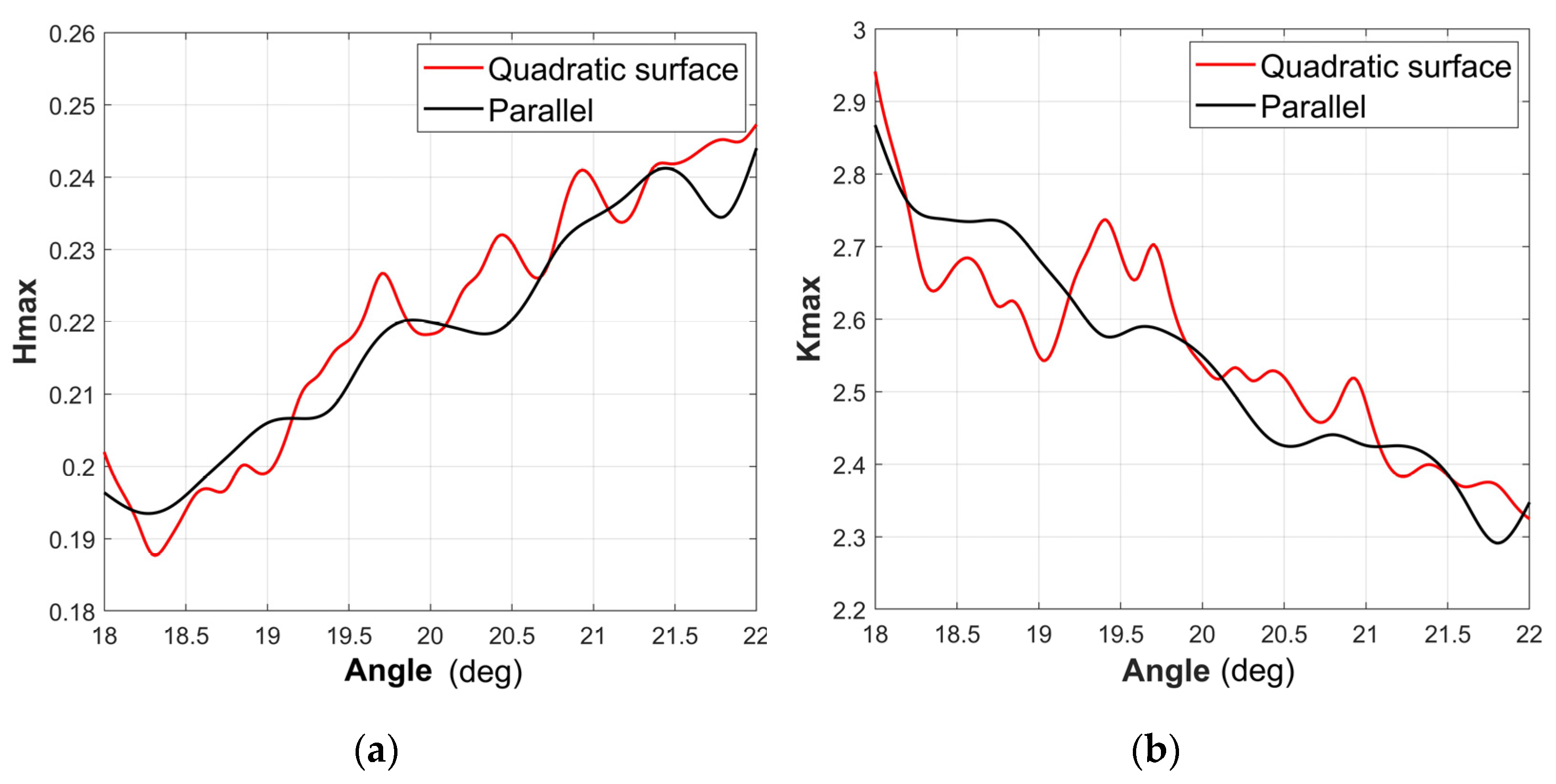
To further explore the properties of quadratic surface blade rows, only the quadratic term coefficient of the cross-section equation was changed, and the simulation calculations were performed separately. In the resulting data, the quadratic term coefficient is expressed in n and the linear term coefficient is expressed in m. The simulation results for a subset of surface blade rows are listed in Table 4, and the comparison of quadratic blade rows with parallel blade rows based on a congruous average angle is shown in Figure 7. It can be seen from Table 4 and Figure 7 that the quadratic blade rows performed better than the parallel blade rows when n was taken as −60 to 60. Therefore, in order to further optimize the structural parameters of the blade rows, it is necessary to consider the surface structure parameters n and m with the blade row height h for parameter optimization.

Table 4.
Pumping performance of quadratic surface blade rows, with different parameters.

Figure 7.
Comparison of pumping performance between blade rows with parallel and quadratic surface based on a congruous average angle. (a) Hmax; (b) Kmax.
4. Structure Parameter Optimization of Blade Rows with Quadratic Surfaces
4.1. Experiment Design
Based on the results of analysis above, the three factors of blade row height h and blade row structural parameters m and n were taken as the input factors. The maximum compression ratio Kmax and the maximum pumping speed Hmax were taken as the output objectives of an orthogonal simulation experiment. The levels of the optimization parameters are presented in Table 5. Other constant structural parameters are consistent with the compression blade rows of the DN-63 TMP.

Table 5.
Levels of input factors.
4.2. Simulation Experiment Results and Discussion
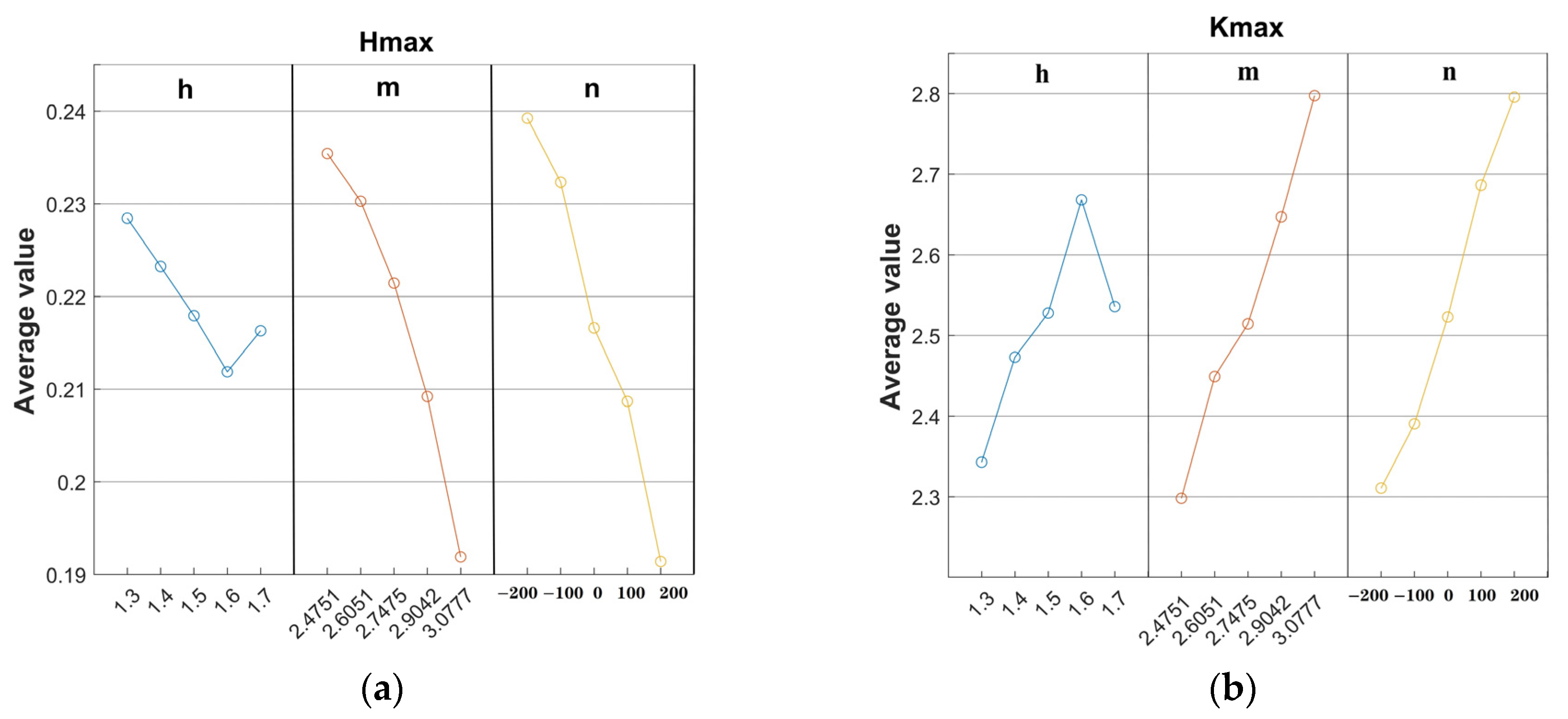
According to the experimental design, a series of simulation experiments were carried out. The results of the simulation experiment are shown in Table 6. In addition, according to the mean value analysis method, the effects of the three parameters, namely, h, m, and n, on the maximum compression ratio and the maximum pumping speed factor are given in Figure 8. It is obvious from Figure 8 that it is difficult to obtain a set of optimal parameters that provide the single-stage blade row with a great compression ratio and wide pumping speed simultaneously. Therefore, it is necessary to use an intelligent optimization algorithm to choose the structural parameters, such as a genetic algorithm, Gaussian process regression, or particle swarm optimization (PSO).

Table 6.
The results of the simulation experiments.

Figure 8.
The influence of the parameters on the maximum compression ratio and the maximum pumping speed factor. (a) Hmax; (b) Kmax.
4.3. SVR-PSO Multi-Objective Optimization Algorithm and Optimized Results
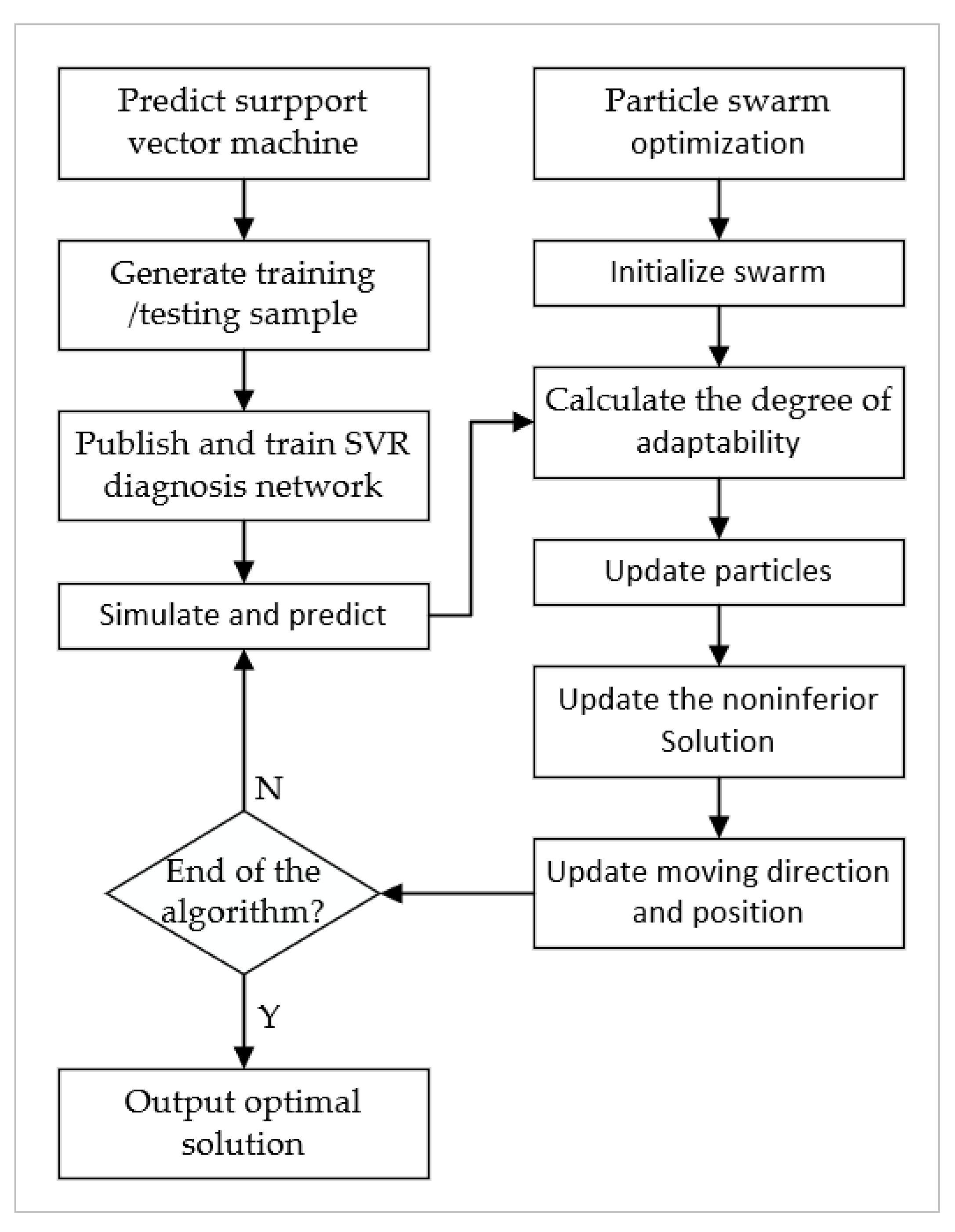
PSO is a global optimization algorithm derived from the simulation of the foraging movement behavior of bird and fish populations. It has the advantages of a good global search ability and ease of implementation when dealing with multi-objective optimization problems. However, it is difficult to obtain the precise optimal result via PSO because the solution may remain hovering around the global optimal solution, which prompted researchers to adopt other parameters and modeling algorithms to improve the search capabilities of particle swarm optimization algorithms such as support vector machines (SVRs) [27]. SVRs use an algorithm to solve regression and fitting problems after improving on the basis of SVM. Some researchers have employed the hybrid optimization algorithm based on SVR and PSO to solve the problem of parameter optimization, and it has been proven that the SVR-PSO optimization algorithm performs well in multi-objective optimization problems [28,29]. In this study, the hybrid optimization algorithm based on SVR and PSO, programmed in MATLAB, was applied to search the optimal quadratic surface structure parameter combination for a high compression ratio and a wide maximum pumping speed. The SVR-PSO model establishment process is shown in Figure 9.

Figure 9.
Flow chart of the SVR-PSO model establishment.
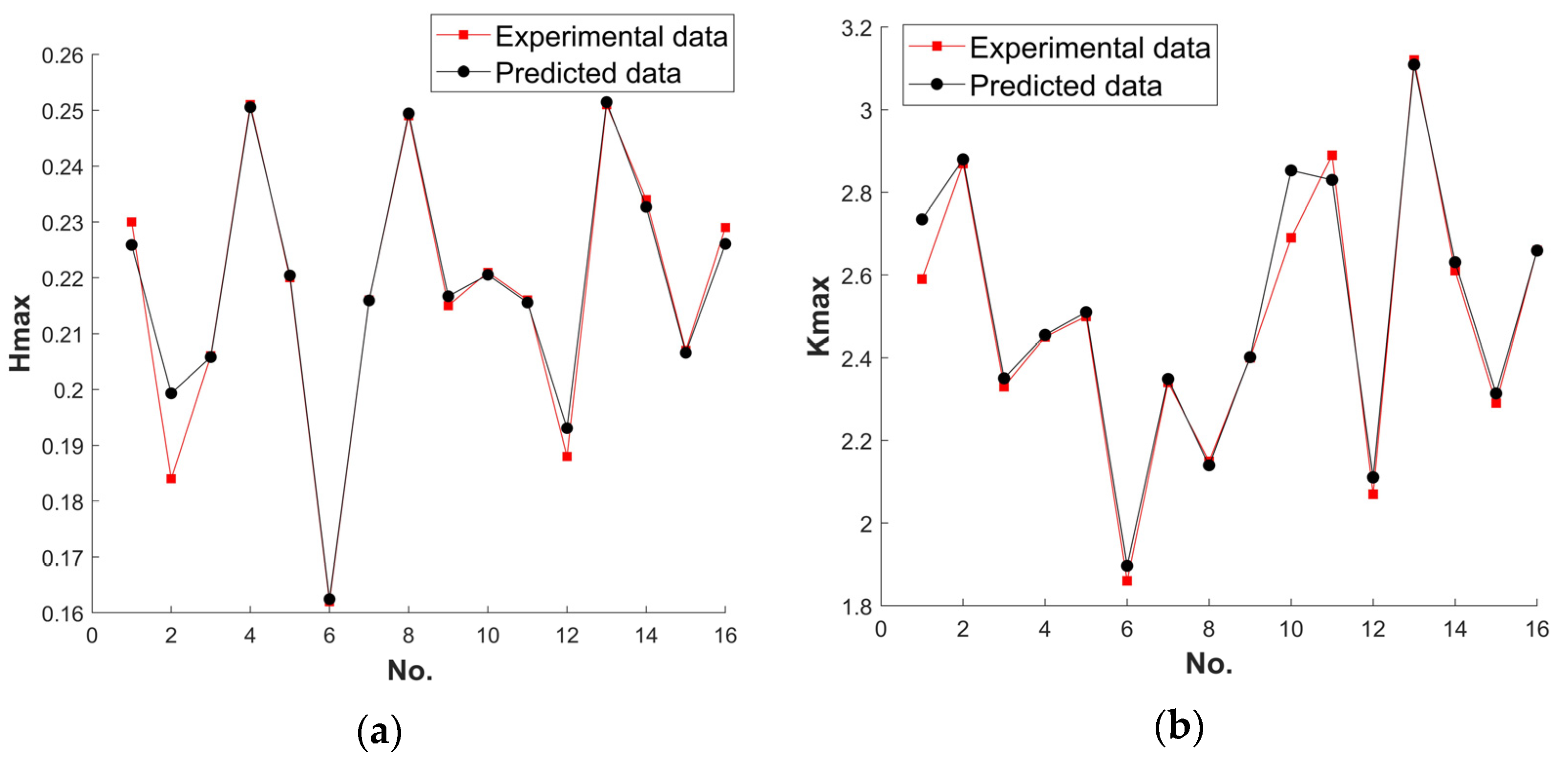
The simulation experimental data from Table 6 are utilized to acquire the SVR training model, based on which we obtained the prediction data. Figure 10 shows the error between experimental data and the predicted data by SVR. The average relative error between the experimental data and the predicted data of Hmax was 1.08%, and the average relative error between the experiment data and the predicted data of Kmax was 1.41%, demonstrating that the SVR training model possesses a great prediction effect.

Figure 10.
Comparison of experimental data with SVR prediction results. (a)Hmax; (b) Kmax.
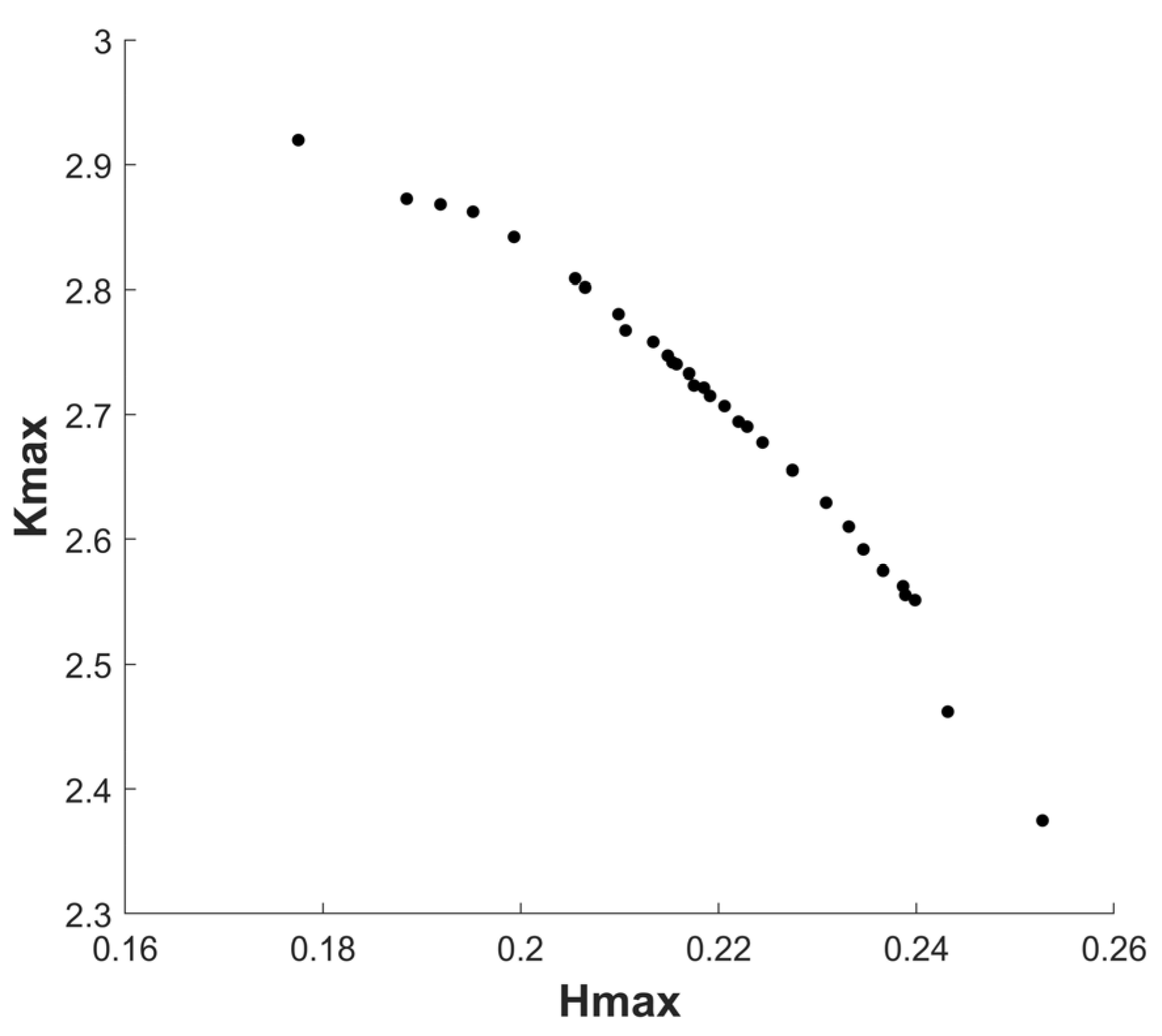
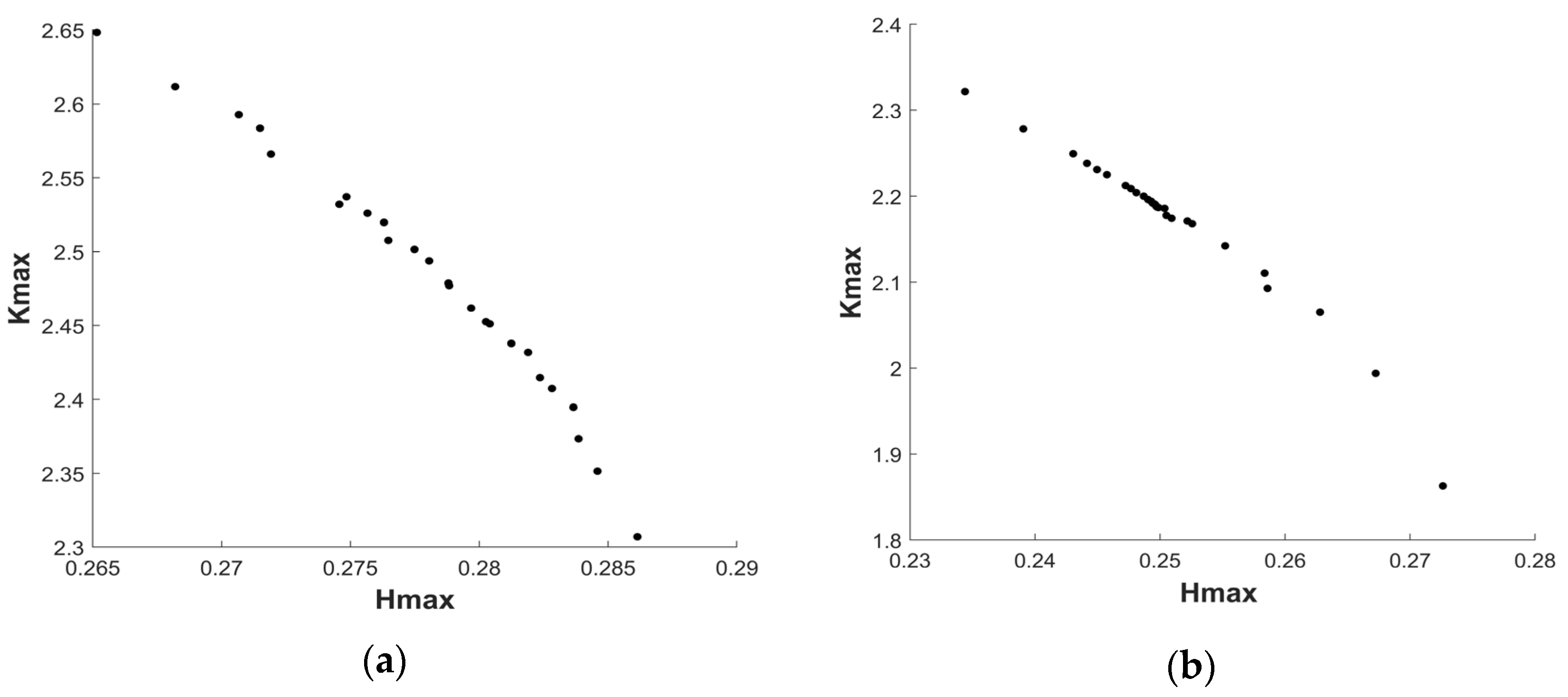
Based on the SVR-PSO multi-objective optimization algorithm, the structure parameter optimization of blade rows with quadratic surfaces was carried out. Figure 11 illustrates the Pareto optimal solution sets of Hmax and Kmax. In Figure 11, it is evident that Hmax and Kmax are negatively correlated, that is, there is no combination of structural parameters that can enable both Hmax and Kmax to reach their maximum values concurrently. However, from the Pareto optimal solution sets of Hmax and Kmax, structural parameters can be selected according to a specific requirement, such as a higher compression ratio, while the pumping speed remains constant or slightly increase.

Figure 11.
Multi-objective optimization results.
From the Pareto optimal solution sets of Hmax and Kmax, six sets of structural parameters were selected and verified by simulation experiments. Table 7 shows that the relative error between the experiment data and the predicted data of ranged from 0.46% to 4.11%, demonstrating the high precision and reliability of the Pareto optimal solution from SVR-PSO. Compared with the data prior to optimization, the degree of improvement in pumping performance is given in Table 8. It can be seen that (1) as shown in No. 1 of Table 8, Hmax was found to be increased by 4.6% while Kmax was found to be increased by 10.35%. (2) As shown in No. 2 of Table 8, Hmax was found to be increased by 6.91% while Kmax was found to be increased by 7.53%. This demonstrates that, compared with the parallel blades, the compression single-stage blade rows with quadratic surface structures were able to effectively increase the maximum compression ratio and the maximum pumping speed factor simultaneously. In addition, the SVR-PSO optimization algorithm achieved admirable multi-objective optimization of the structure parameters of blade rows with quadratic surfaces.

Table 7.
Multi-objective optimization validation data.

Table 8.
The comparison of experimental simulation data and the Parato optimal solution sets.
4.4. Optimization of Turbine-Stage and Intermediate-Stage Blade Rows
Through the optimization results of the surface parameters of the compression-stage blade rows, it can be seen that the quadratic surface blade had a certain effect on improving the pumping performance of the single-stage TMP, so the same optimization treatment was considered for the turbine stage and the intermediate stage, which were listed in Table 1. The pumping performance values of the turbine-stage and the intermediate-stage blade rows are listed in Table 9. The levels of the optimization parameters for turbine-stage blade rows are presented in Table 10. The levels of the optimization parameters for intermediate-stage blade rows are exhibited in Table 11.

Table 9.
Pumping performance of parallel blade rows.

Table 10.
Levels of input factors for the turbine stage.

Table 11.
Levels of input factors for the intermediate stage.
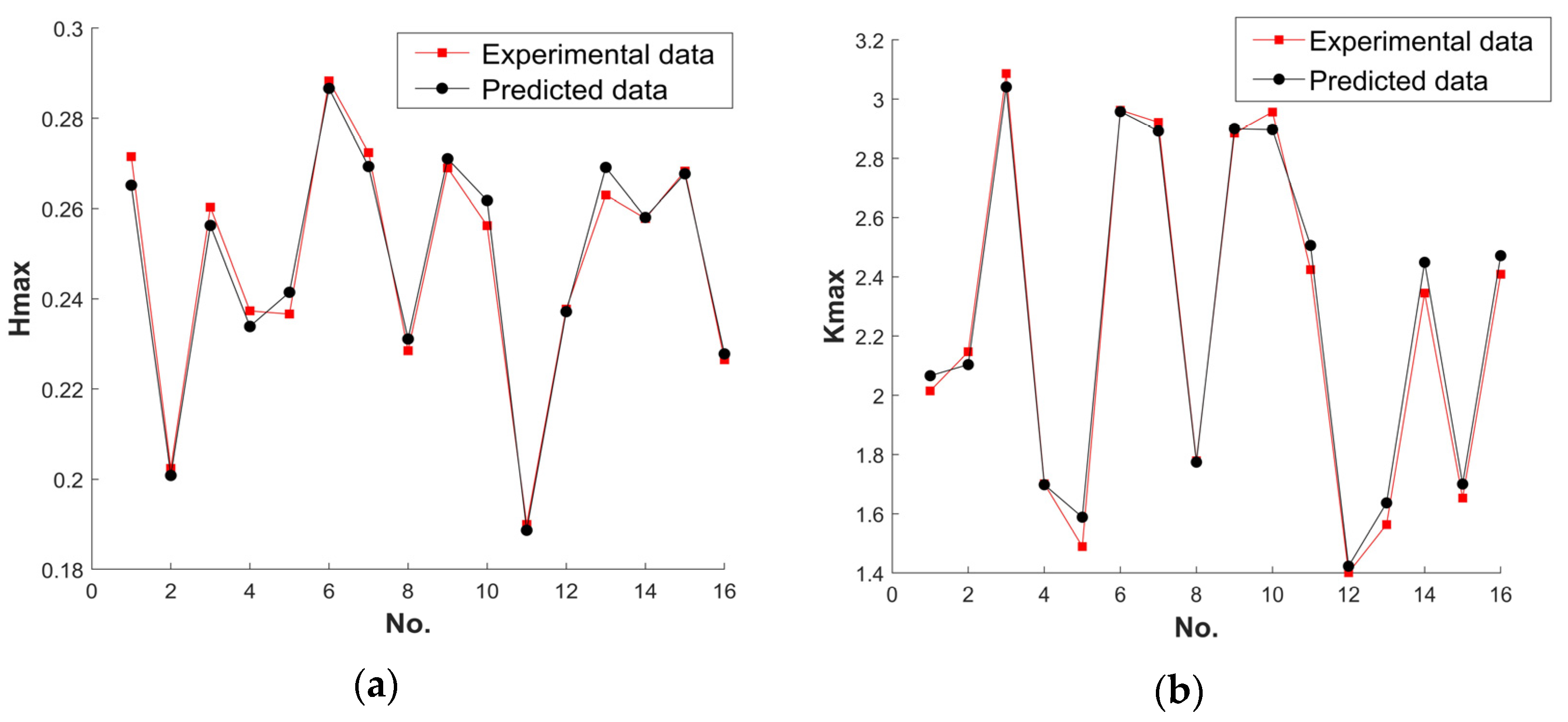
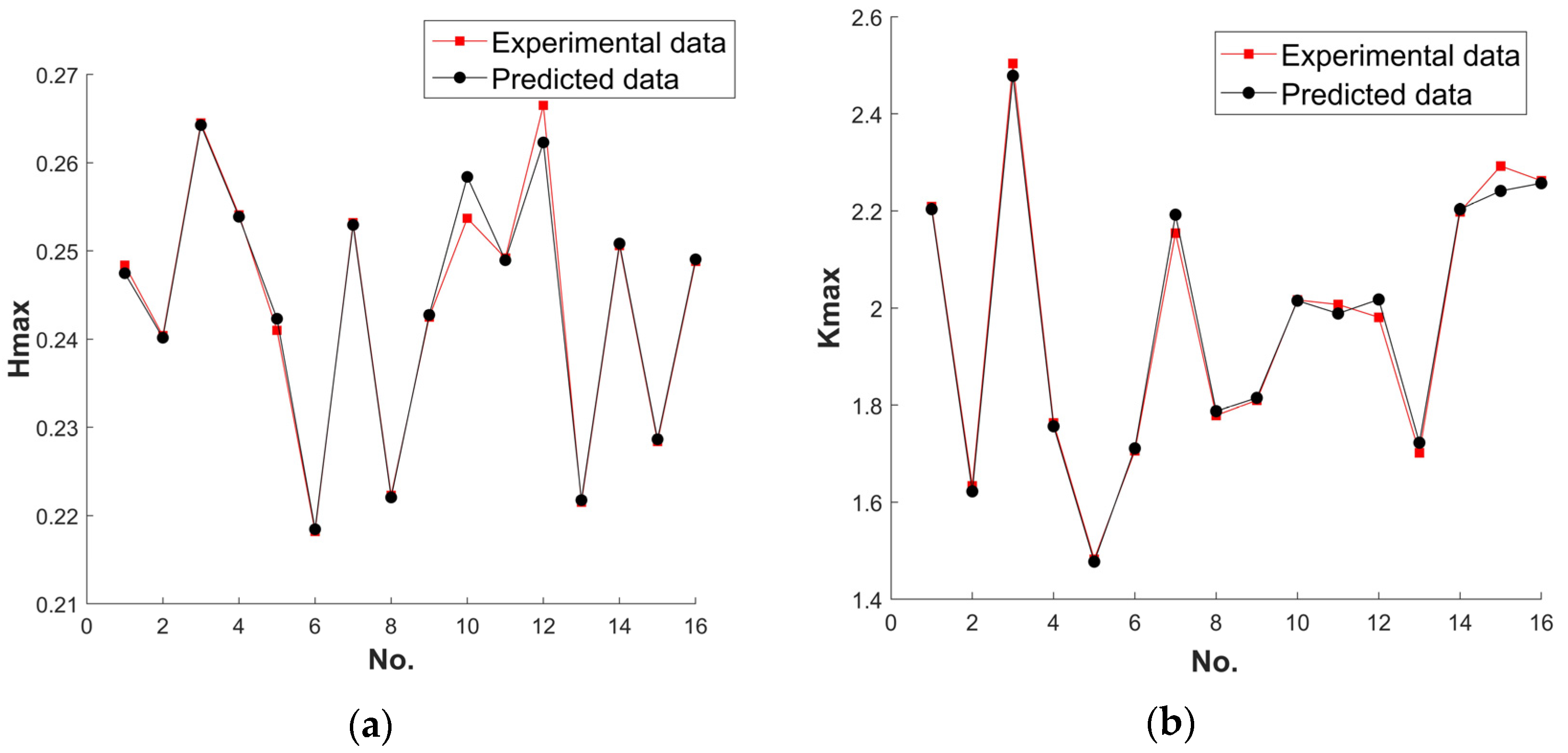
The simulation data of the orthogonal experiment are used for the model training of the SVR. As shown separately in Figure 12 and Figure 13, the prediction results of the trained SVR model were compared with the experimental simulation data for the turbine stage and the intermediate stage. The average relative errors of the predicted and true values of the SVR model for the Hmax and Kmax of the turbine stage were 1.13% and 2.27%, respectively. The average relative errors of the predicted and true values of the SVR model for the Hmax and Kmax of the intermediate stage were 0.35% and 0.77%, respectively. This shows that the SVR prediction models for the pumping performance of turbine stage and the intermediate stage both possess a certain level of reliability.

Figure 12.
Comparison of experimental data with SVR prediction results for the turbine stage. (a) Hmax; (b) Kmax.

Figure 13.
Comparison of experimental data with SVR prediction results for the intermediate stage. (a) Hmax; (b) Kmax.
Based on the SVR-PSO multi-objective optimization algorithm, the structure parameter optimization of blade rows of turbine stage and intermediate stage with quadratic surface could be carried out. In Figure 14 and Figure 14b illustrate the Pareto optimal solution sets of the Hmax and Kmax of the turbine stage and the intermediate stage separately.

Figure 14.
Multi-objective optimization results. (a) Turbine stage; (b) intermediate stage.
In order to verify the effectiveness of the SVR-PSO optimization algorithm for the turbine stage and the intermediate stage, the optimization results of the turbine and intermediate stages were simulated and verified. Table 12 shows that the relative error between the experiment data and the predicted data for turbine stage ranged from 0.11% to 9.48%, proving the certain precision and reliability of the Pareto optimal solution by SVR-PSO.

Table 12.
Multi-objective optimization validation data for the turbine stage.
Compared with the pumping performance of the parallel blade rows listed in Table 9, it can be seen from No. 1 in Table 12 that (1) Hmax was found to be decreased by 0.87%, while Kmax was found to be increased by 4.1%. (2) No. 5 in Table 12 shows that Hmax was found to be decreased by 0.51%, while Kmax was found to be increased by 6.94%. For the turbine stage of the DN-63 TMP, although using the blade rows with quadratic surface structure improved the compression ratio, it caused the loss of some of the pumping speed. Considering that the pumping speed is crucial for the turbine stage, in this stage, it is still more appropriate to use parallel blade rows.
Table 13 shows that the relative error between the experimental data and the predicted data for the intermediate stage ranges from 1.80% to 5.18%, proving the high precision and reliability of the Pareto optimal solution from SVR-PSO. Compared with the pumping performance of the parallel blade rows listed in Table 9, it can be seen from No. 1 in Table 13 that (1) Hmax was found to be decreased by 2.53% while Kmax was found to be increased by 9.15%. (2) No. 5 in Table 13 shows that Hmax was found to be decreased by 1%, while Kmax was found to be increased by 7.53%. It is obvious that for the intermediate stage of the DN-63 molecular pump, the maximum compression ratio can be improved without reducing the pumping speed by using blade rows with quadratic surfaces.

Table 13.
Multi-objective optimization validation data for the intermediate stage.
According to Formula (6), when a quadratic surface blade row is utilized on a compression stage blade row and a transition stage blade row, the DN-63 turbomolecular pump can increase the maximum compression ratio by 61.2%. According to Formulas (8)–(10), this results in a slight increase in pumping speed, but for the turbine stage, it is still better to use parallel blade rows. The DN-63 compression stage rotor and the transition stage rotor can effectively improve the performance of the molecular pump by using quadratic surface blade rows. Compared with the quadratic surface structure in Table 3, the hybrid optimization SVR-PSO method can increase the maximum compression ratio by 9.52% and the maximum pumping speed factor by 4.57%.
5. Verification of the Model
5.1. Test Method
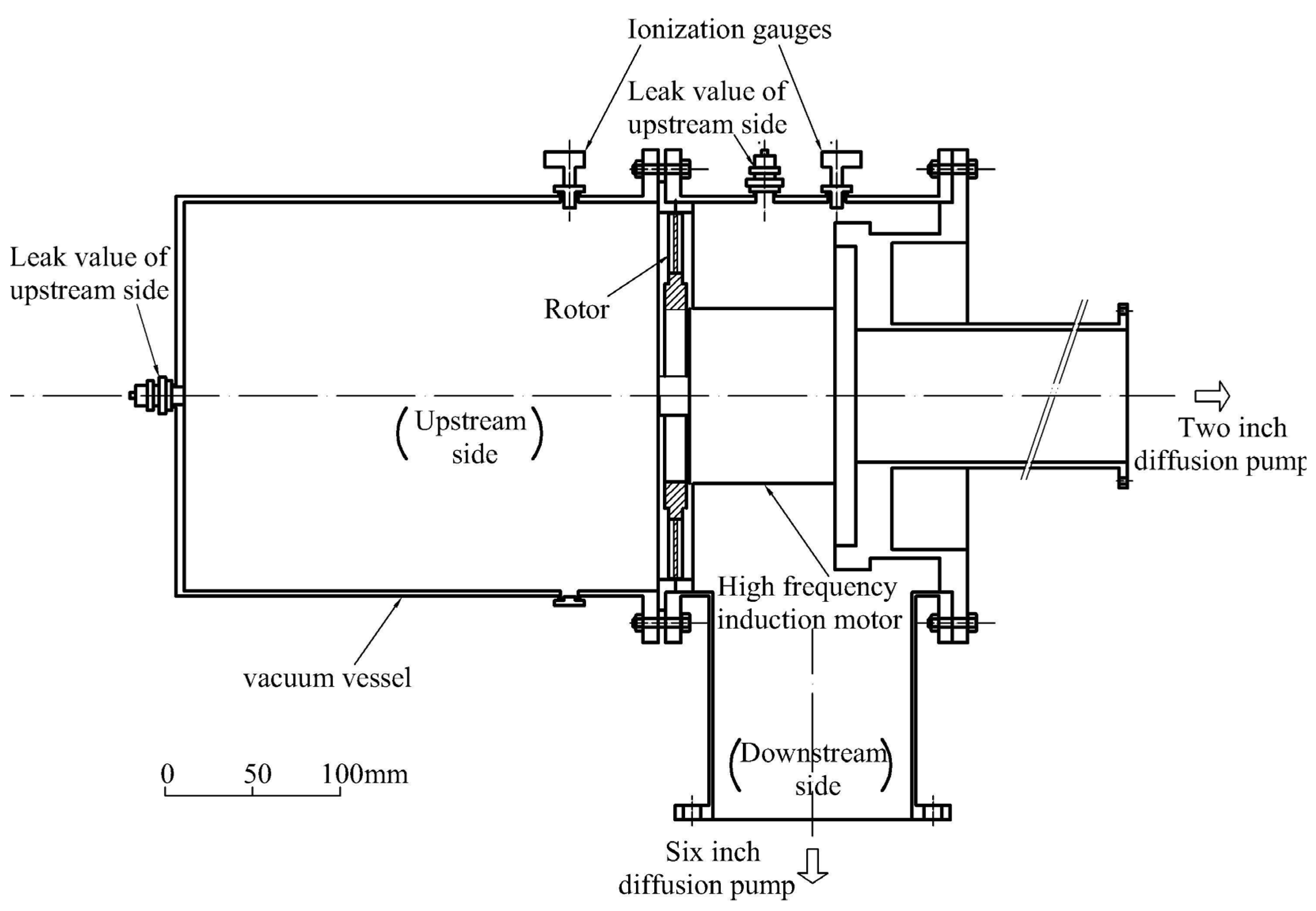
The experimental data used to verify the accuracy of the model in this paper were derived from the experimental data on the pumping performance of Sawada’s publicly available single-stage TMP [30]. In his experiment, the main part of the experimental device consisted of a stainless-steel vacuum vessel and a rotor driven by a high-frequency induction motor, while the measurement of vacuum pressure was conducted by hot-filament ionization gauges. By controlling the air flow of the leakage valve on both the upstream and downstream sides, the relationship between the pressure ratio and the pumping speed factor were obtained. Six-inch and two-inch diffusion pumps served as auxiliary devices to provide a backing vacuum and to prevent exhaust from the coil and motor bearings from affecting the results of the experiment, respectively. The device measurement diagram is shown in Figure 15 [30].

Figure 15.
Experimental apparatus diagram [30].
After obtaining the experimental data, the pressure ratio and pumping factor were plotted at different blade speeds, which were approximately straight lines. The extrapolated values of the maximum compression ratio and the maximum pumping factor were obtained by extending the straight line, that is, the intersection of the straight line and the horizontal and vertical axes.
5.2. Performance Testing of TMP Rotor
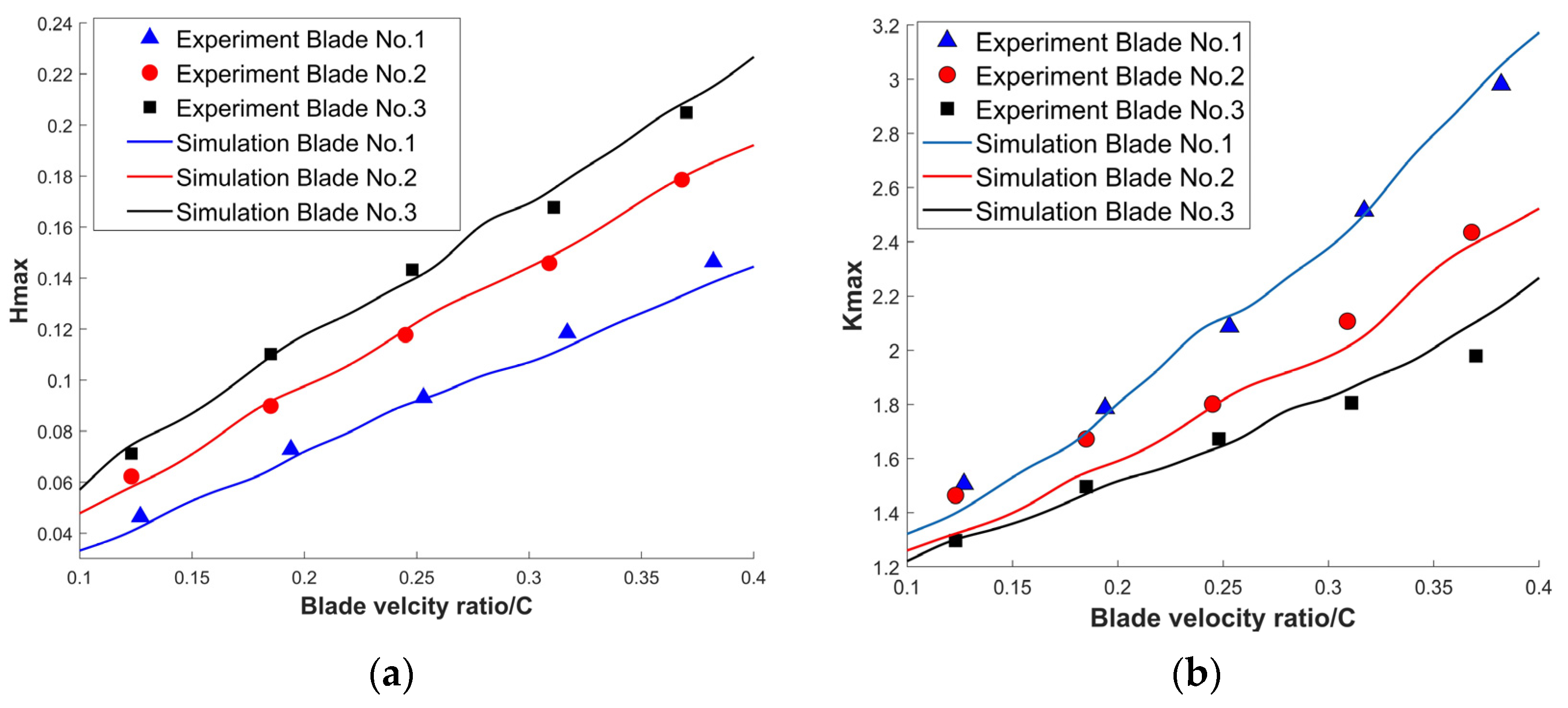
A comparison of the pumping performances of the three blades was conducted, the geometric parameters of which are shown in Table 14 [30]. The pumping performances of the three blade rows, as calculated by simulation, are shown in Figure 16 [30], and detailed data are listed in Table 15. The relative error with experimental data is listed in Table 16. Table 16 shows that the relative error between the simulation data and the experimental data for the aerodynamic model ranged from 2.47% to 4.83%, proving the high precision and reliability of the aerodynamic model established in this study.

Table 14.
Geometric parameters of the rotor [30].

Figure 16.
Comparison of pumping performances [14]. (a) Hmax; (b) Kmax.

Table 15.
Comparison of pumping performances.

Table 16.
Average relative error with experimental data.
6. Conclusions
- Several types of curved blade were presented with the ability to improve the pumping performance of TMP. Compared with parallel blades and other curved blades, the positive quadratic surface blades showed better pumping performances, with good promotion and application value for practical engineering.
- The hybrid optimization SVR-PSO method was proposed in order to obtain the structural parameters of the rotor blade for the highest pumping speed and maximum compression ratio. This increased the maximum compression ratio by 10.35% and the maximum pumping speed factor by 4.61%.
- The relative errors of the maximum pumping speed factor and the maximum compression ratio between the results of the aerodynamic model simulation and the experimental data were 2.47–4.83% and 2.47–4.79%, respectively. This means that the thin gas aerodynamic model showed good precision. Therefore, the model can also be utilized to develop new molecular pumps with different pumping performance requirements.
Author Contributions
Z.C.: conceptualization; funding acquisition; formal analysis; methodology; investigation; writing. W.W.: data curation; investigation; resources; formal analysis; writing. Z.L.: data curation; investigation. H.Y.: funding acquisition; investigation; methodology; validation. All authors have read and agreed to the published version of the manuscript.
Funding
This research was supported by Natural Science Foundation of Changsha City, China (Grant No. kq2208273), Fundamental Research Funds for the Central Universities of Central South University (2022zzts0786); Guangdong Basic and Applied Basic Research Foundation (Grant No. 2022A1515011226), Project of State Key Laboratory of High Performance Complex Manufacturing, Central South University (Grant ZZYJKT2022-10), Central Government Funds for Guiding Local Scientific and Technological Development (Grant No.2021Szvup167), and the project of Guangdong Provincial Key Laboratory of Manufacturing Equipment Digitization (Grant No. 2020B1212060014).
Data Availability Statement
Not applicable.
Conflicts of Interest
The authors declare no conflict of interest.
References
- Gordeeva, U.S. Efficiency of the Drag Stage Application in the Multistage Turbomolecular Vacuum Pump. In Proceedings of the Oil and Gas Engineering (OGE) Conference, Omsk, Russia, 26–29 February 2020. [Google Scholar]
- Han, B.; Huang, Z.; Le, Y. Design aspects of a large scale turbomolecular pump with active magnetic bearings. Vacuum 2017, 142, 96–105. [Google Scholar] [CrossRef]
- Schopphoff, A.; Braunschweig, F. Generation of UHV with Turbomolecular Pump and Dry Backing Pump Meeting the demand for completely hydrocarbon-free vacuum. Vak. Forsch. Prax. 2017, 29, 22–25. [Google Scholar] [CrossRef]
- Zhang, X.; Han, B.; Liu, X.; Chen, Y.; Zhai, L. Prediction and experiment of DC- bias iron loss in radial magnetic bearing for a small scale turbomolecular pump. Vacuum 2019, 163, 224–235. [Google Scholar] [CrossRef]
- Li, X.; Zhang, Y.; Ge, S.; Qian, J.; Miao, W. Portable linear ion trap mass spectrometer with compact multistage vacuum system and continuous atmospheric pressure interface. Analyst 2019, 144, 5127–5135. [Google Scholar] [CrossRef] [PubMed]
- Chen, Y.-H.; Lu, I.C. Novel ion source for a portable mass spectrometer. Rapid Commun. Mass Spectrom. 2021, 35, e8503. [Google Scholar] [CrossRef]
- Zhang, Y.; Tang, J.; Xu, X.; Huang, Z. Optimal design of magnetically suspended high-speed rotor in turbo-molecular pump. Vacuum 2021, 193, 110510. [Google Scholar] [CrossRef]
- Mao, K.; Liu, G. An improved braking control method for the magnetically levitated TMP with a fast transient response. Vacuum 2018, 148, 312–318. [Google Scholar] [CrossRef]
- Huang, Z.; Han, B.; Mao, K.; Peng, C.; Fang, J. Mechanical stress and thermal aspects of the rotor assembly for turbomolecular pumps. Vacuum 2016, 129, 55–62. [Google Scholar] [CrossRef]
- Hsu, C.N. Experimental and performance analyses of a turbomolecular pump rotor system. Vacuum 2015, 121, 260–273. [Google Scholar] [CrossRef]
- Ge, M.; Petkovsek, M.; Zhang, G.; Jacobs, D.; Coutier-Delgosha, O. Cavitation dynamics and thermodynamic effects at elevated temperatures in a small Venturi channel. Int. J. Heat Mass Transf. 2021, 170, 120970. [Google Scholar] [CrossRef]
- Huang, Z.; Han, B.; Le, Y. Modeling method of the modal analysis for turbomolecular pump rotor blades. Vacuum 2017, 144, 145–151. [Google Scholar] [CrossRef]
- Barfuss, H. The Development of the Turbomolecular Pump within the last three Decades Enabler of digital Technologies and High Vacuum Workhorse. Vak. Forsch. Prax. 2018, 30, 20–24. [Google Scholar] [CrossRef]
- Sun, K.; Zhang, S.W.; Han, F.; Zhao, F.; Zhang, Z.J.; Han, J. A New Modeling Method to Reveal Pumping Mechanism of Turbomolecular Pump. J. Appl. Fluid Mech. 2021, 14, 165–173. [Google Scholar] [CrossRef]
- Huang, Z.; Han, B.; Le, Y. Multidisciplinary Design Strategies for Turbomolecular Pumps with Ultrahigh Vacuum Performance. IEEE Trans. Ind. Electron. 2019, 66, 9549–9558. [Google Scholar] [CrossRef]
- Wang, S.; Ninokata, H.; Merzari, E.; Lei, K.; Luo, X.; Lu, L.; Kase, K. Numerical study of a single blade row in turbomolecular pump. Vacuum 2009, 83, 1106–1117. [Google Scholar] [CrossRef]
- Funke, R.; Schnacke, E.; Voss, G. A novel turbomolecular pump for R&D and analytical applications: General remarks on development and applications. Vak. Forsch. Prax. 2015, 27, 30–35. [Google Scholar] [CrossRef]
- Sharipov, F. Numerical simulation of turbomolecular pump over a wide range of gas rarefaction. J. Vac. Sci. Technol. A 2010, 28, 1312–1315. [Google Scholar] [CrossRef]
- Versluis, R.; Dorsman, R.; Thielen, L.; Roos, M.E. Numerical investigation of turbomolecular pumps using the direct simulation Monte Carlo method with moving surfaces. J. Vac. Sci. Technol. A 2009, 27, 543–547. [Google Scholar] [CrossRef]
- Sengil, N.; Edis, F.O. Fast cell determination of the DSMC molecules in multi-stage turbo molecular pump design. Comput. Fluids 2011, 45, 202–206. [Google Scholar] [CrossRef]
- Shams, M.; Sheykhzadeh, H.; Taghavi, M. Mathematical Simulation of Free Molecular Flow in a Three-Dimensional Turbomolecular Pump with Nonparallel Blades. J. Dispers. Sci. Technol. 2010, 31, 299–306. [Google Scholar] [CrossRef]
- Sun, K.; Zhang, S.W.; Li, Y.J.; Zhang, Z.J.; Li, H.T.; Mu, R.Y. Monte Carlo simulation of gas free molecular flow in turbo molecular pump’s inlet tube. Mol. Simul. 2018, 44, 1261–1269. [Google Scholar] [CrossRef]
- Bird, G.A. Effect of inlet guide vanes and sharp blades on the performance of a turbomolecular pump. J. Vac. Sci. Technol. A Vac. Surf. Film. 2011, 29, 011016. [Google Scholar] [CrossRef]
- Sengil, N. Performance increase in turbomolecular pumps with curved type blades. Vacuum 2012, 86, 1764–1769. [Google Scholar] [CrossRef]
- Li, Y.; Chen, X.; Jia, Y.; Liu, M.; Wang, Z. Numerical investigation of three turbomolecular pump models in the free molecular flow range. Vacuum 2014, 101, 337–344. [Google Scholar] [CrossRef]
- Li, Y.; Chen, X.; Guo, W.; Li, D.; Wang, Q.; Feng, K. Accurate simulation of turbomolecular pumps with modified algorithm by 3D direct simulation Monte Carlo method. Vacuum 2014, 109, 354–359. [Google Scholar] [CrossRef]
- Chen, Z.; Zhou, H.; Yan, Z.; Han, F.; Yan, H. Machining characteristics of 65 vol.% SiCp/Al composite in micro-WEDM. Ceram. Int. 2021, 47, 13533–13543. [Google Scholar] [CrossRef]
- Ghazvinian, H.; Mousavi, S.-F.; Karami, H.; Farzin, S.; Ehteram, M.; Hossain, M.S.; Fai, C.M.; Bin Hashim, H.; Singh, V.P.; Ros, F.C.; et al. Integrated support vector regression and an improved particle swarm optimization-based model for solar radiation prediction. PLoS ONE 2019, 14, e0217634. [Google Scholar] [CrossRef] [PubMed]
- Wang, L.; Li, Z.P.; Adenutsi, C.D.; Zhang, L.; Lai, F.P.; Wang, K.J. A novel multi-objective optimization method for well control parameters based on PSO-LSSVR proxy model and NSGA-II algorithm. J. Pet. Sci. Eng. 2021, 196, 107694. [Google Scholar] [CrossRef]
- Sawada, T.; Murakami, K. The Axial Flow Molecular Pump (I). Shinku 1971, 14, 33–41. [Google Scholar] [CrossRef]
Disclaimer/Publisher’s Note: The statements, opinions and data contained in all publications are solely those of the individual author(s) and contributor(s) and not of MDPI and/or the editor(s). MDPI and/or the editor(s) disclaim responsibility for any injury to people or property resulting from any ideas, methods, instructions or products referred to in the content. |
© 2023 by the authors. Licensee MDPI, Basel, Switzerland. This article is an open access article distributed under the terms and conditions of the Creative Commons Attribution (CC BY) license (https://creativecommons.org/licenses/by/4.0/).

