
Oblique Crashworthiness Analysis of Steel Circular Tubes: Parametric Study on Wall Thickness Effect and Critical Loading Angle Identification

 ,
, 

Abstract
:1. Introduction
2. Methodology
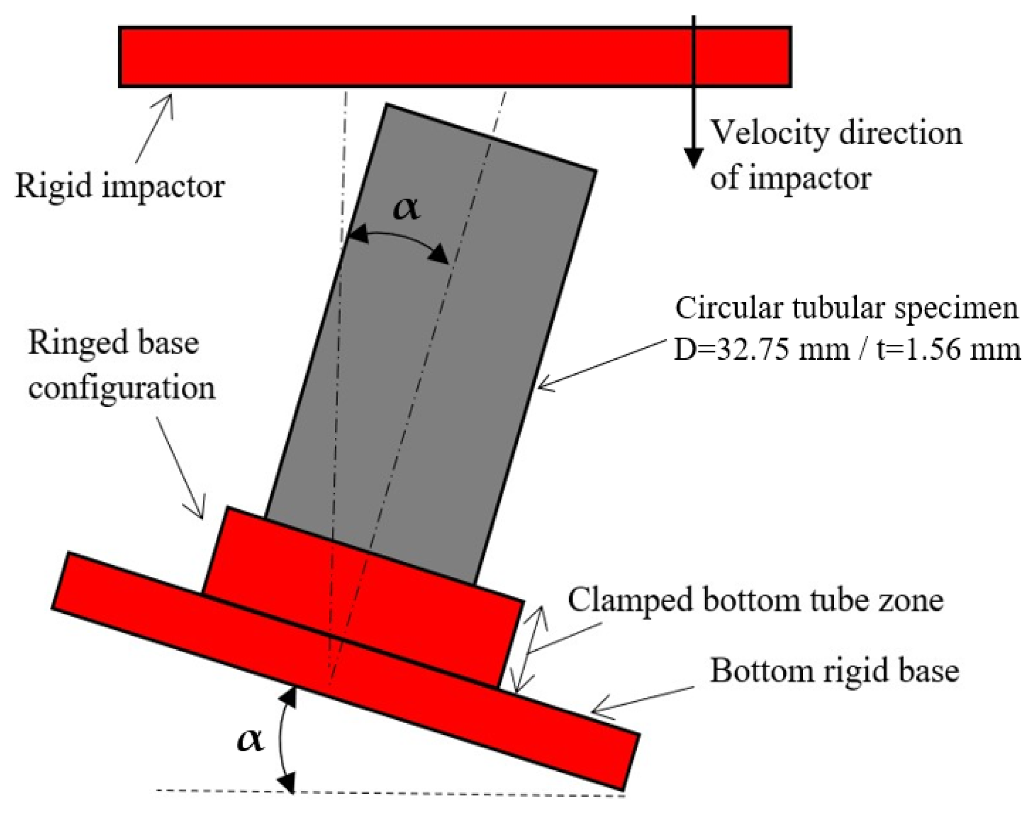
2.1. Experiments
2.2. Crashworthiness Indicators
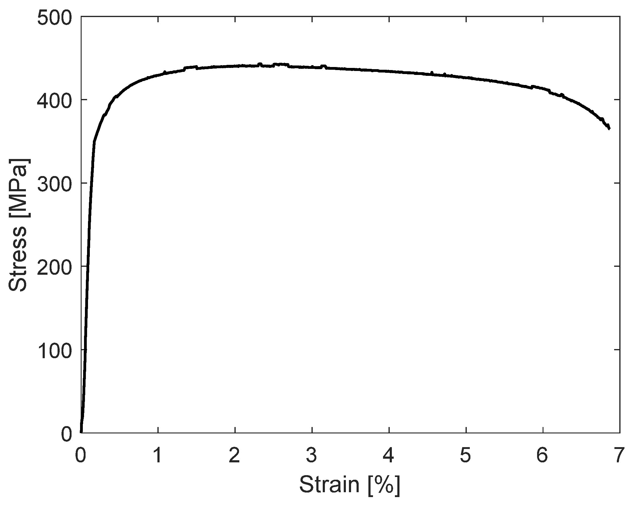
2.3. Material Characterization
2.4. Finite Element Modeling
3. Results
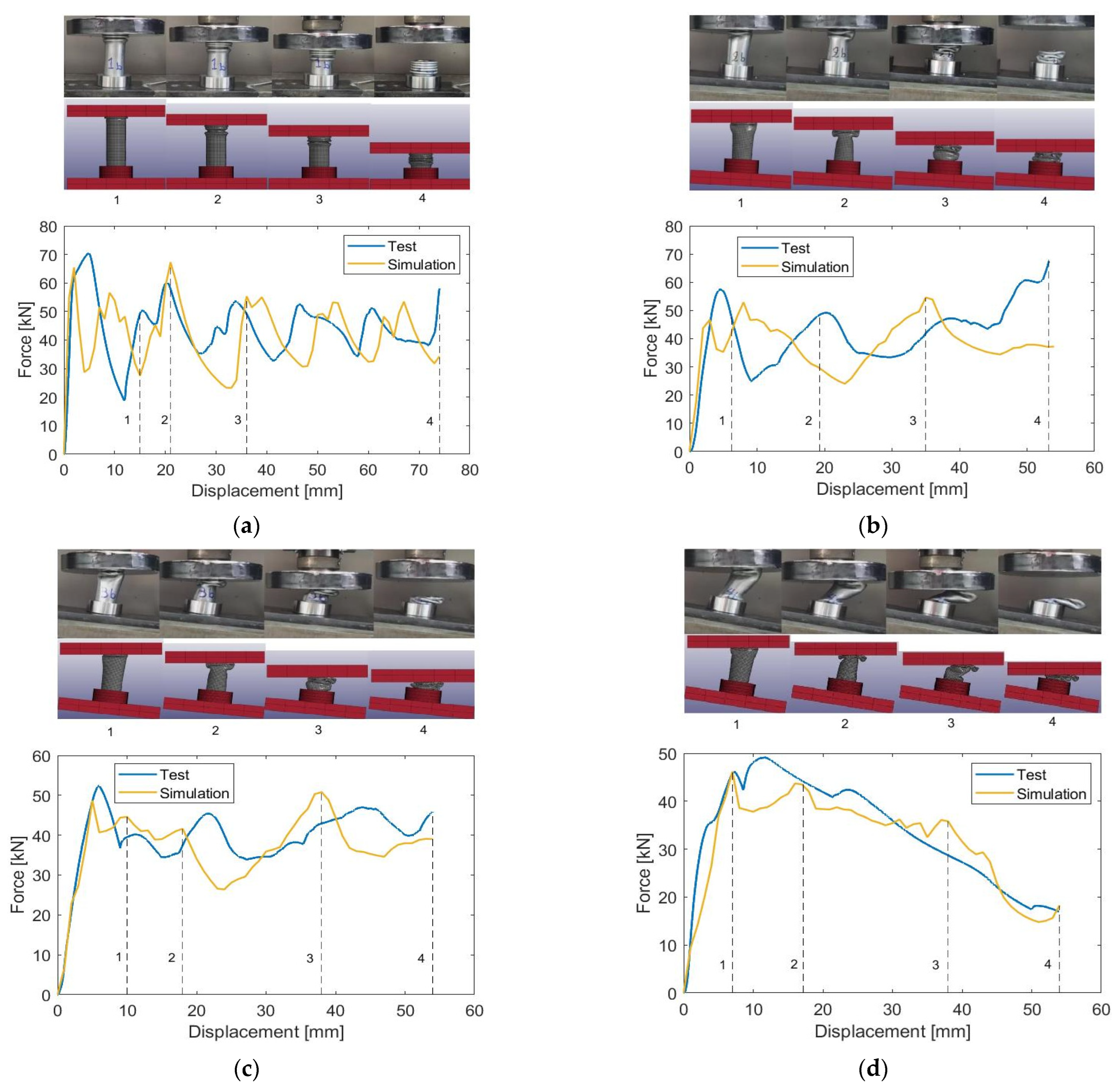
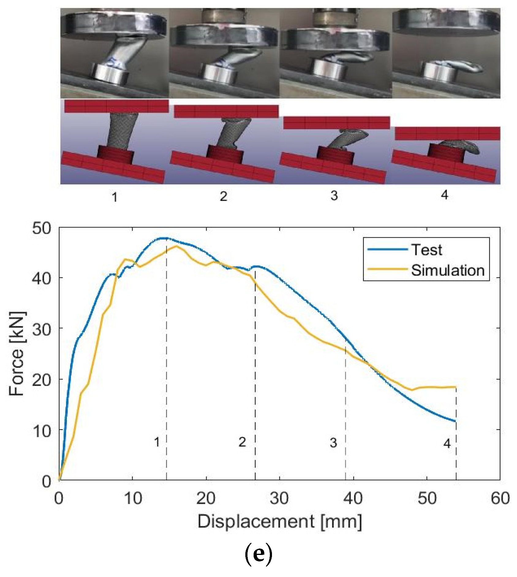
3.1. Modeling Validation
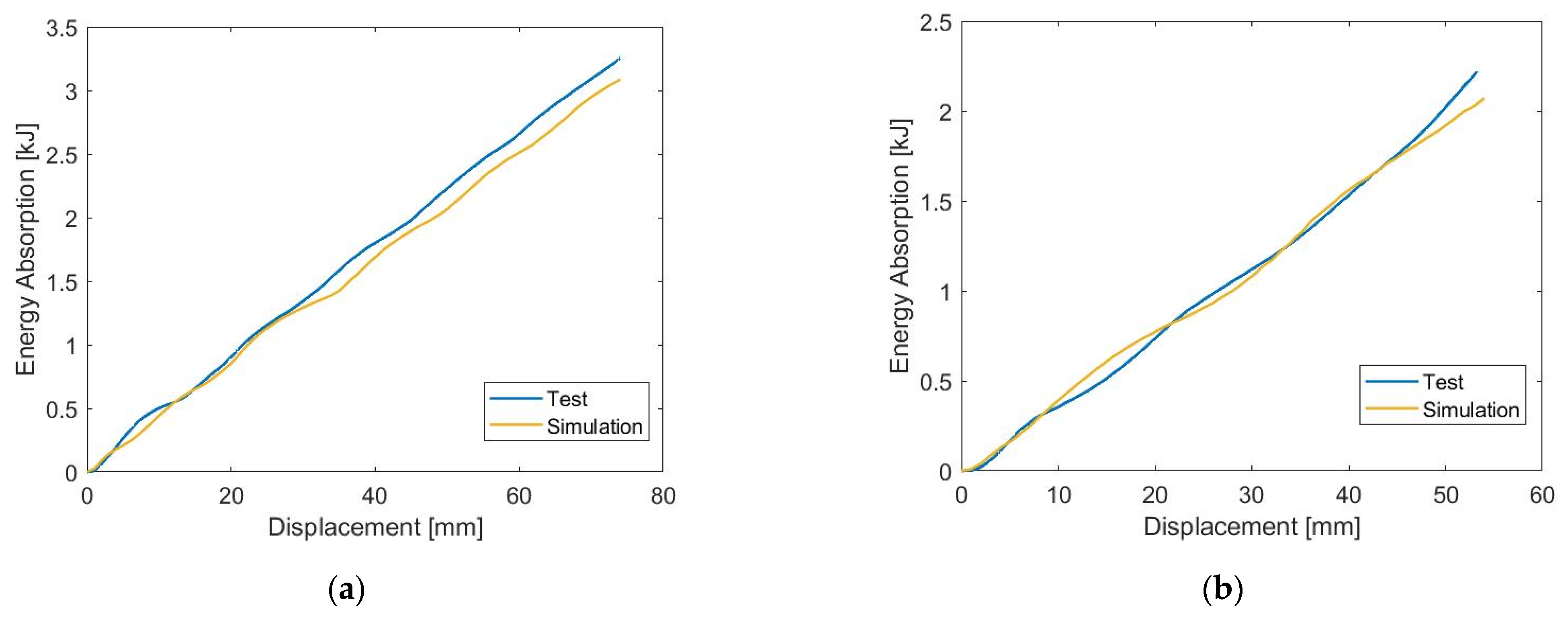
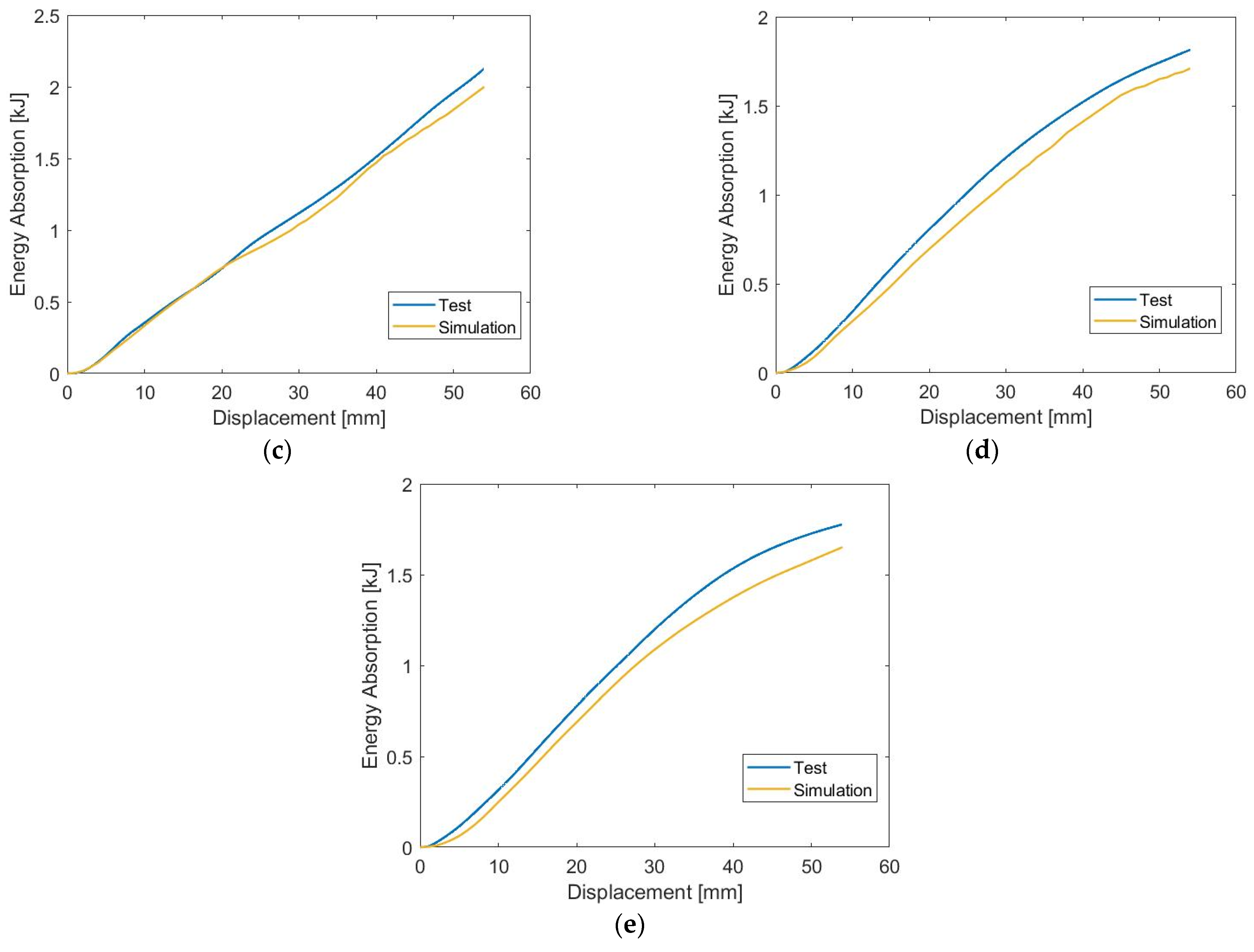
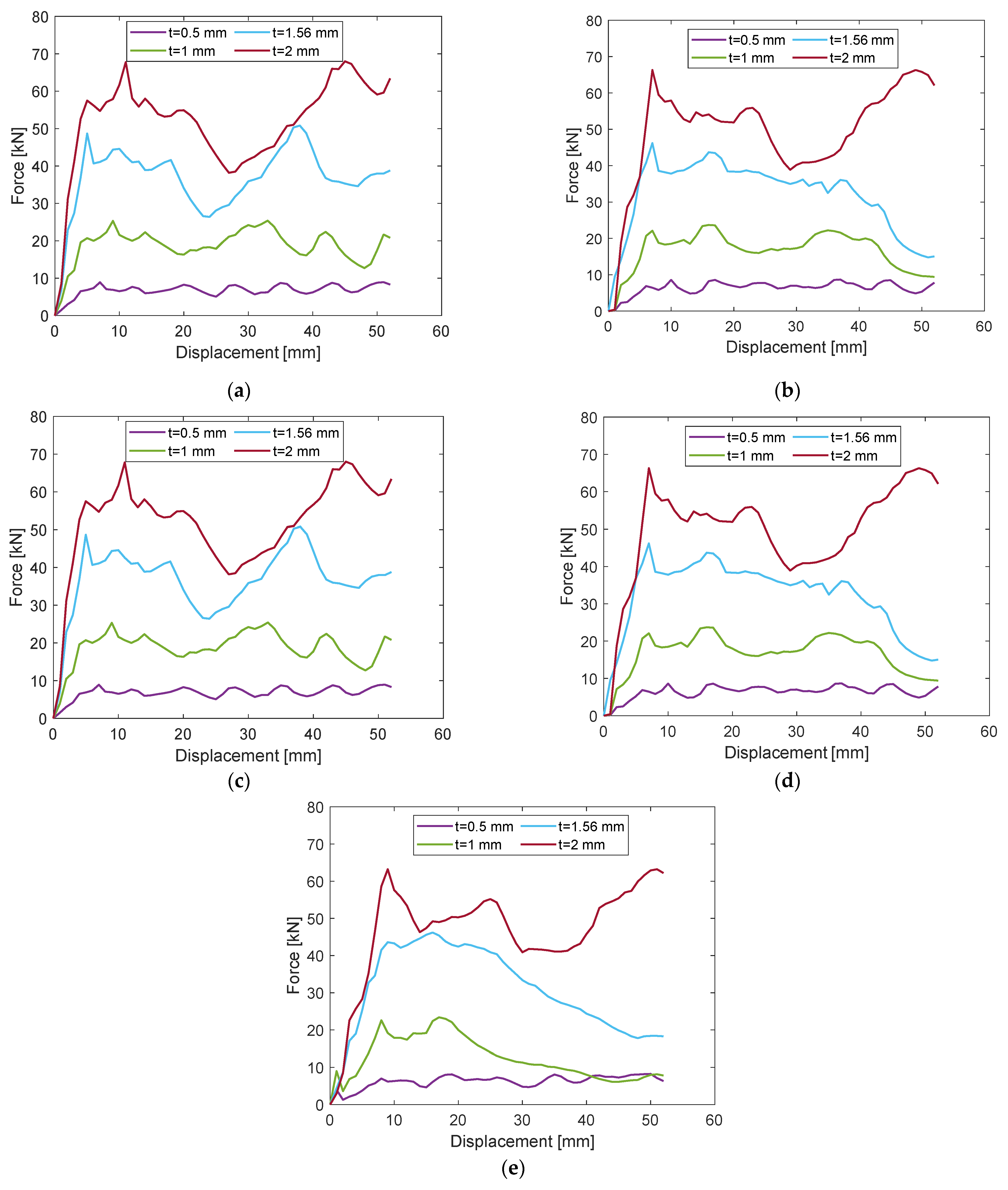
3.1.1. Force-Displacement Characteristics
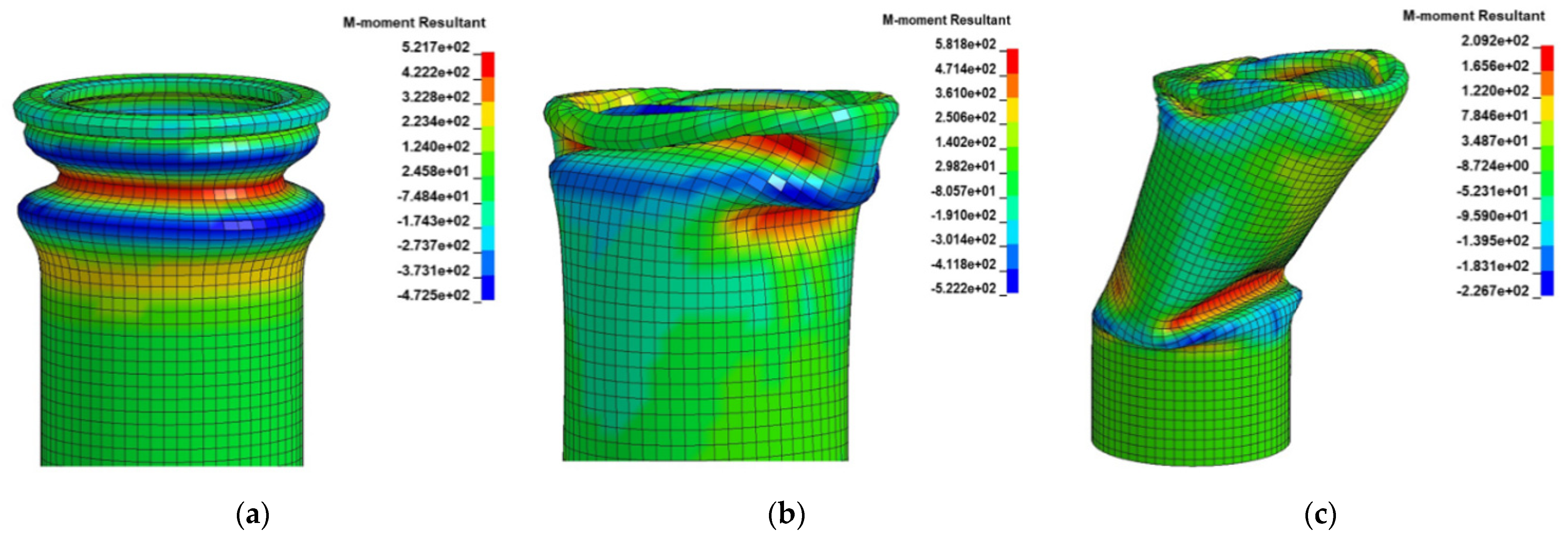
3.1.2. Collapse Mechanisms
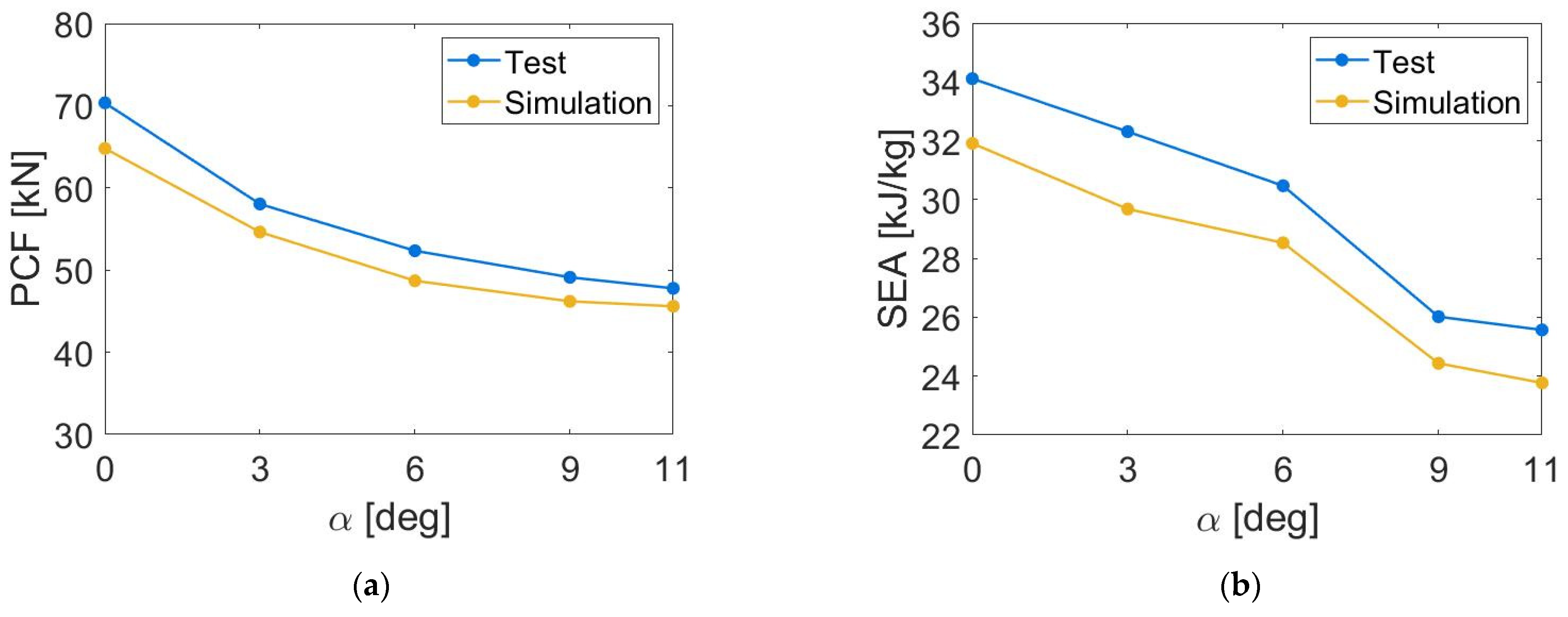
3.2. Crushing Angle Effect
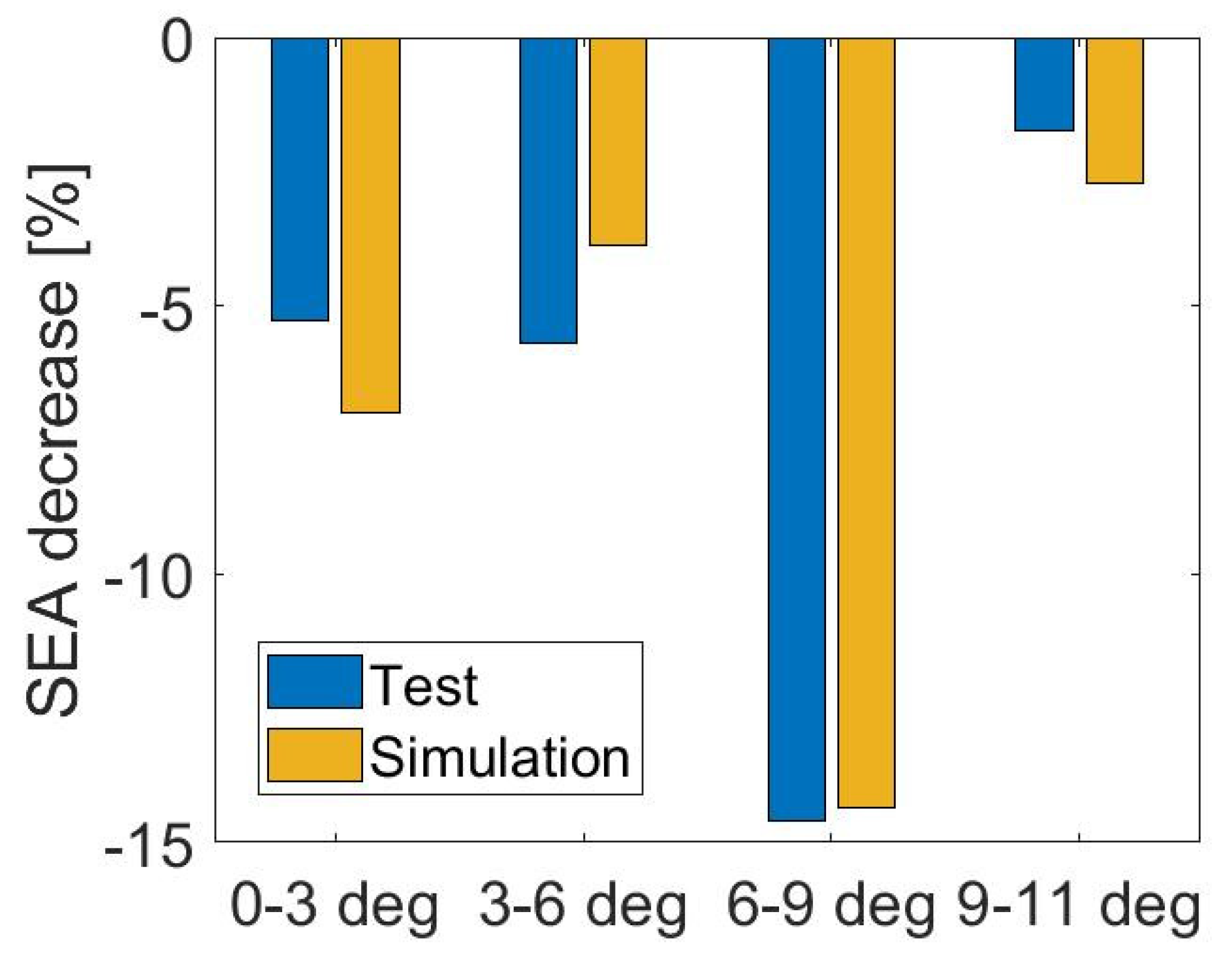
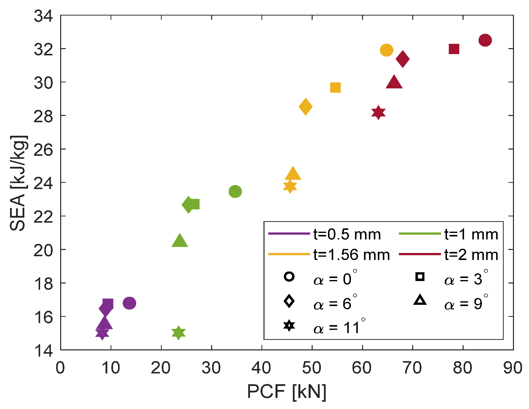
3.3. Wall Thickness Effect
4. Conclusions
Author Contributions
Funding
Data Availability Statement
Conflicts of Interest
References
- Pei, T.S.; Saffe, S.N.M.; Rusdan, S.A.; Hamran, N.N.N. Oblique impact on crashworthiness: Review. Int. J. Eng. Technol. Sci. 2017, 4, 32–48. [Google Scholar] [CrossRef]
- Kim, H.S.; Wierzbicki, T. Numerical and analytical study on deep biaxial bending collapse of thin-walled beams. Int. J. Mech. Sci. 2000, 42, 1947–1970. [Google Scholar] [CrossRef]
- Han, D.C.; Park, S.H. Collapse behavior of square thin-walled columns subjected to oblique loads. Thin-Walled Struct. 1999, 35, 167–184. [Google Scholar] [CrossRef]
- Reyes, A.; Langseth, M.; Hopperstad, O.S. Crashworthiness of aluminum extrusions subjected to oblique loading: Experiments and numerical analyses. Int. J. Mech. Sci. 2002, 44, 1965–1984. [Google Scholar] [CrossRef]
- Karantza, K.D.; Manolakos, D.E. Crashworthiness analysis of square aluminum tubes subjected to oblique impact: Experimental and numerical study on the initial contact effect. Metals 2022, 12, 1862. [Google Scholar] [CrossRef]
- Song, J. Numerical simulation on windowed tubes subjected to oblique impact and a new method for the design of obliquely loaded tubes. Int. J. Impact Eng. 2013, 54, 192–205. [Google Scholar] [CrossRef]
- Azimi, M.B.; Asgari, M.; Salaripoor, H. A new homo-polygonal multi-cell structures under axial and oblique impacts; considering the effect of cell growth in crashworthiness. Int. J. Crashworthiness 2020, 25, 628–647. [Google Scholar] [CrossRef]
- Pirmohammad, S.; Marzdashti, S.E. Crushing behavior of new designed multi-cell members subjected to axial and oblique quasi-static loads. Thin-Walled Struct. 2016, 108, 291–304. [Google Scholar] [CrossRef]
- Qi, C.; Yang, S.; Dong, F. Crushing analysis and multiobjective crashworthiness optimization of tapered square tubes under oblique impact loading. Thin-Walled Struct. 2012, 59, 103–119. [Google Scholar] [CrossRef]
- Tarlochan, F.; Samer, F.; Hamouda, A.M.S.; Ramesh, S.; Khalid, K. Design of thin wall structures for energy absorption applications: Enhancement of crashworthiness due to axial and oblique impact forces. Thin-Walled Struct. 2013, 71, 7–17. [Google Scholar] [CrossRef]
- Qi, C.; Yang, S. Crashworthiness and lightweight optimisation of thin-walled conical tubes subjected to an oblique impact. Int. J. Crashworthiness 2014, 19, 334–351. [Google Scholar] [CrossRef]
- Gao, Q.; Wang, L.; Wang, Y.; Wang, C. Crushing analysis and multiobjective crashworthiness optimization of foam-filled ellipse tubes under oblique impact loading. Thin-Walled Struct. 2016, 100, 105–112. [Google Scholar] [CrossRef]
- Baykasoglu, C.; Baykasoglu, A.; Cetin, M.T. A comparative study on crashworthiness of thin-walled tubed with functionally graded thickness under oblique impact loadings. Int. J. Crashworthiness 2019, 24, 453–471. [Google Scholar] [CrossRef]
- Mohammadiha, O.; Ghariblu, H. Crush behavior optimization of multi-tubes filled by functionally graded foam. Thin-Walled Struct. Part B 2016, 98, 627–639. [Google Scholar] [CrossRef]
- Crutzen, Y.; Inzaghi, A.; Mogilevsky, M.; Albertini, C. Computer Modelling of the Energy Absorption Process in Box-Type Structures under Oblique Impact; Automotive Automation Ltd.: Shropshire, UK, 1996; pp. 1293–1298. [Google Scholar]
- Patel, S.; Vusa, V.R.; Soares, C.G. Crashworthiness analysis of polymer composites under axial and oblique impact loading. Int. J. Mech. Sci. 2019, 156, 221–234. [Google Scholar] [CrossRef]
- Zarei, H.R. Experimental and numerical crashworthiness investigation of hybrid composite aluminium tubes under dynamic axial and oblique loading. Int. J. Automot. Eng. 2015, 5, 1084–1093. [Google Scholar]
- Jamal-Omidi, M.; Benis, A.C. A numerical study on energy absorption capability of lateral corrugated composite tube under axial crushing. Int. J. Crashworthiness 2021, 26, 147–158. [Google Scholar] [CrossRef]
- Zhang, Y.; Wang, J.; Chen, T.; Lu, M.; Jiang, F. On crashworthiness design of double conical structures under oblique impact. Int. J. Veh. Des. 2018, 7, 20–45. [Google Scholar] [CrossRef]
- Ma, F.; Liang, H.; Pu, Y.; Wang, Q.; Zhao, Y. Crashworthiness analysis and multi-objective optimization for honeycomb structures under oblique impact loading. Int. J. Crashworthiness 2022, 27, 1128–1139. [Google Scholar] [CrossRef]
- Hallquist, J.O. LS-DYNA Theory Manual; Livermore Software Technology Corporation: Livermore, CA, USA, 2006. [Google Scholar]
- Liu, W.; Jin, L.; Luo, Y.; Deng, X. Multi-objective crashworthiness optimization of tapered star-shaped tubed under oblique impact. Int. J. Crashworthiness 2021, 26, 328–342. [Google Scholar] [CrossRef]
- Pled, F.; Yan, W.; Wen, C. Crushing modes of aluminium tubes under axial compression. In Proceedings of the 5th Australasian Congress on Applied Mechanics, Brisbane, Australia, 10–12 December 2007; pp. 178–180. Available online: https://hal.archivesouvertes.fr/hal-01056929 (accessed on 25 May 2022).
- Kilicaslan, C. Numerical crushing analysis of aluminum foam-filled corrugated single- and double- circular tubes subjected to axial impact loading. Thin-Walled Struct. 2015, 96, 82–94. [Google Scholar] [CrossRef]
- Haufe, A.; Schweizerhof, K.; Dubois, P. Properties and Limits: Review of Shell Element Formulations; Developer Forum DYNA More: Filderstadt, Germany, 2013. [Google Scholar]


| Test Case | Crushing Angle α (°) | Effective Initial Length (mm) | Impactor Displacement (mm) |
|---|---|---|---|
| 1 | 0 | 99 | 74 |
| 2 | 3 | 68 | 54 |
| 3 | 6 | 68 | 54 |
| 4 | 9 | 68 | 54 |
| 5 | 11 | 68 | 54 |
| Description | Variable | Value |
|---|---|---|
| Density (kg/m3) | ρ | 7830 |
| Young modulus (GPa) | E | 200 |
| Poisson ratio (-) | ν | 0.3 |
| Yield stress (MPa) | σY | 335 |
| Ultimate tensile strength (MPa) | UTS | 442 |
| Failure plastic strain (%) | εpf | 6.7 |
| Crushing Angle α (°) | Deviation in PCF (%) | Deviation in EA (%) | Deviation in CFE (%) |
|---|---|---|---|
| 0 | 7.89 | 6.11 | 2.36 |
| 3 | 5.87 | 8.10 | 2.59 |
| 6 | 6.96 | 6.16 | 0.56 |
| 9 | 5.94 | 5.87 | 0.08 |
| 11 | 4.56 | 7.04 | 2.56 |
| Crushing Angle | Method | PCF (kN) | MCF (kN) | EA (kJ) | SEA (kJ/kg) | CFE (-) |
|---|---|---|---|---|---|---|
| α = 0° | Test | 70.35 | 43.99 | 3.26 | 34.11 | 0.63 |
| Simulation | 64.80 | 41.30 | 3.06 | 31.91 | 0.64 | |
| α = 3° | Test | 58.04 | 41.71 | 2.26 | 32.31 | 0.72 |
| Simulation | 54.63 | 38.37 | 2.07 | 29.68 | 0.70 | |
| α = 6° | Test | 52.35 | 39.51 | 2.13 | 30.47 | 0.75 |
| Simulation | 48.70 | 36.96 | 2.00 | 28.53 | 0.76 | |
| α = 9° | Test | 49.12 | 33.59 | 1.81 | 26.02 | 0.68 |
| Simulation | 46.20 | 31.62 | 1.71 | 24.44 | 0.68 | |
| α = 11° | Test | 47.78 | 32.90 | 1.77 | 25.57 | 0.69 |
| Simulation | 45.61 | 30.59 | 1.65 | 23.77 | 0.67 |
| Crushing Angle | Wall Thickness (mm) | PCF (kN) | MCF (kN) | EA (kJ) | SEA (kJ/kg) | CFE (-) |
|---|---|---|---|---|---|---|
| α = 0° | 0.5 | 13.67 | 6.95 | 0.51 | 16.79 | 0.51 |
| 1.0 | 34.70 | 19.43 | 1.44 | 23.46 | 0.56 | |
| 1.56 | 64.80 | 41.30 | 3.06 | 31.91 | 0.64 | |
| 2.0 | 84.40 | 53.83 | 3.98 | 32.50 | 0.64 | |
| α = 3° | 0.5 | 9.38 | 6.93 | 0.36 | 16.75 | 0.74 |
| 1.0 | 26.56 | 18.80 | 0.98 | 22.71 | 0.71 | |
| 1.56 | 54.63 | 38.37 | 2.07 | 29.68 | 0.70 | |
| 2.0 | 78.21 | 52.96 | 2.75 | 31.98 | 0.68 | |
| α = 6° | 0.5 | 8.93 | 6.82 | 0.35 | 16.47 | 0.76 |
| 1.0 | 25.42 | 18.77 | 0.96 | 22.67 | 0.74 | |
| 1.56 | 48.70 | 36.96 | 2.00 | 28.53 | 0.76 | |
| 2.0 | 68.00 | 51.96 | 2.70 | 31.38 | 0.76 | |
| α = 9° | 0.5 | 8.70 | 6.42 | 0.33 | 15.52 | 0.74 |
| 1.0 | 23.67 | 16.92 | 0.86 | 20.43 | 0.71 | |
| 1.56 | 46.20 | 31.62 | 1.71 | 24.44 | 0.68 | |
| 2.0 | 66.30 | 49.53 | 2.57 | 29.91 | 0.75 | |
| α = 11° | 0.5 | 8.26 | 6.21 | 0.32 | 15.00 | 0.75 |
| 1.0 | 23.43 | 12.44 | 0.63 | 15.02 | 0.53 | |
| 1.56 | 45.61 | 30.59 | 1.65 | 23.77 | 0.67 | |
| 2.0 | 63.18 | 46.67 | 2.43 | 28.18 | 0.74 |
Disclaimer/Publisher’s Note: The statements, opinions and data contained in all publications are solely those of the individual author(s) and contributor(s) and not of MDPI and/or the editor(s). MDPI and/or the editor(s) disclaim responsibility for any injury to people or property resulting from any ideas, methods, instructions or products referred to in the content. |
© 2023 by the authors. Licensee MDPI, Basel, Switzerland. This article is an open access article distributed under the terms and conditions of the Creative Commons Attribution (CC BY) license (https://creativecommons.org/licenses/by/4.0/).
Share and Cite
Karantza, K.D.; Papantoniou, I.G.; Lykakos, S.S.A.; Manolakos, D.E. Oblique Crashworthiness Analysis of Steel Circular Tubes: Parametric Study on Wall Thickness Effect and Critical Loading Angle Identification. Machines 2023, 11, 542. https://doi.org/10.3390/machines11050542
Karantza KD, Papantoniou IG, Lykakos SSA, Manolakos DE. Oblique Crashworthiness Analysis of Steel Circular Tubes: Parametric Study on Wall Thickness Effect and Critical Loading Angle Identification. Machines. 2023; 11(5):542. https://doi.org/10.3390/machines11050542
Chicago/Turabian StyleKarantza, Konstantina D., Ioannis G. Papantoniou, Stavros S. A. Lykakos, and Dimitrios E. Manolakos. 2023. "Oblique Crashworthiness Analysis of Steel Circular Tubes: Parametric Study on Wall Thickness Effect and Critical Loading Angle Identification" Machines 11, no. 5: 542. https://doi.org/10.3390/machines11050542