Abstract
The paper presents the measured values of tensile forces acting on transmission idlers in the upper and lower run of a conveyor belt placed on a laboratory machine designed at the Department of Machine and Industrial Design, Faculty of Mechanical Engineering, VSB-Technical University of Ostrava. The tensile forces detected by two strain gauge load cells and recorded using DEWESoft software were used to calculate the friction coefficient, which acts on the surface of the driving drum casing and the conveyor belt. The friction coefficient at the slip point, or during the slippage of the conveyor belt on the rubber or steel casing of the driving drum, was determined for two states of the surfaces that are in contact. Experimental measurements on a laboratory machine determined four values of friction coefficients for two types of drum surfaces and for two states of contact surfaces, which were compared with the recommended standard values. The measured values reached higher values in comparison with the values given by the CSN standards. The highest deviation of 273.3% is achieved using a steel wet surface, and the lowest deviation of 106.3% is achieved when using a rubber dry lining for the driving drum casing. On the presented laboratory machine, it is possible to measure tensile forces for different speeds of movement, different belt angles on the driving drum, various types of belt surfaces, different types of drum casing linings, and different sizes of tension forces for the endless loop of the conveyor belt. For these characteristics of the conveyor belt, the magnitude of the friction coefficient acting between the belt and the drum surfaces can be determined.
1. Introduction
The belt of the belt conveyor is driven by frictional forces that are transmitted between the surface of the driving drum casing/shell and the conveyor belt. Thus, the total movement resistance of the conveyor belt is overcome by the driving forces generated by the belt conveyor drive placed on the driving drums.
In a paper [1], Antoniak presents the theoretical basis used to build a new generation of belt conveyors. These conveyors are characterized by the better energy-saving parameters of their run transport and their higher reliability.
The solution of force relationships for the driving drums is based on Euler (-Eytelwein) Equation (1).
The Euler–Eytelwein formula, written by Leonhard Euler (1707–1783) and Johann Alber Eytelwein (1764–1848), describes the friction of a flat belt surrounding a cylindrical drum [2].
Konyukhov et al. state in [3] that the solution of the generalized Euler–Eytelwein, or the belt friction issue, is a stand-alone task recently formulated for a rope placed in a sliding equilibrium on an arbitrary surface. It brings a new set of benchmark issues for the verification of a rope/beam placed on a surface/solid contact and its algorithms. Not only a pulling force ratio but also the position of the curve on an arbitrary rigid surface, withstanding the motion in the dragging direction, should be verified.
Harada and Hirosato, in article [4], use an endless rope (loop-rope), turning around an endless pulley and an endless winch. As friction forces between the cable and the drum transfer the cable tension, the slipping of the cable, which is dominated by the well-known Euler–Eytelwein formula, is taking into consideration the statics of the E-CDPR. In this paper, a new interpretation of the Euler–Eytelwein’s formula is proposed by using a graph in which the non-slipping condition is expressed as an area in the cable tension.
Konyukhov et al., in articles [5,6,7], state that within the finite element implementation, the isogeometric approach is used to model curvilinear cables, and the rigid surfaces can be defined in general via NURB surface splines. Verification of the finite element algorithm is given using the well-known analytical solution of the Euler–Eytelwein task—a rope placed on a cylindrical surface.
Bulín and Hajžman, in their article [8], present a belt-cylinder interaction model based on the absolute nodal coordinate formulation of beam-finite elements, which take into consideration the nonlinear contact forces acting between a beam and a rigid cylinder.
Ma et al. in paper [9] present an exclusive testing rig that was built to experimentally investigate friction and slip at the elevator traction interface, provided under various traction conditions.
Shi-zai and Meng-gang, in the article [10], present the governing equations developed by them, which are based on catenary theory and the Euler–Eytelwein’s equation. The governing equations of the three-dimensional sliding cable elements, with a known unstressed cable length and with known tensile forces, are respectively developed, accounting for the thermal effect and sliding friction.
Gładysiewicz et al., in article [11], present the primary parameter determining the value of the resistance to motion of the belt conveyor, which is the main resistance coefficient f, and is also referred to as the artificial or fictive friction coefficient. This coefficient is primarily used for calculating belt conveyor resistance to motion accordingly to DIN 22101, PN-93/M-46552, and ISO 5048 standards.
Munzenberger and Wheeler specify in article [12] that the indentation rolling resistance of conveyor belts is an important design consideration for long belt conveyors and can also be important for heavily loaded belt conveyors. Indentation rolling resistance is dependent on the properties of the conveyor belt, including the carcass and bottom cover as well as properties of the conveyor belt, including induced loads, the belt speed, ambient temperature, and the idler roll diameter.
Fedorko et al. describe in article [13] the achieved research results regarding the properties of smooth conveyor belts determined through a tensile loading test to examine the behavior of the inner structure of the belt samples. They present that when the belt is subjected to long-term strain, the belt relaxation effect is observed, and changes may occur to the inner structure of the belt. The tensile test at a constant velocity determines the load strength limit of the strip samples.
Król et al., in article [14], describe a method of measuring movement resistances to motion for a single three-roller idler set with the use of a specially designed measuring stand. The stand allows conducting measurements in real operating conditions and with a variable stream of bulk material.
In article [15], authors Rudolphi and Reicks describe the one-dimensional Winkler foundation and a generalized viscoelastic Maxwell solid model of the belt backing material used to determine the resistance to motion of a conveyor belt over idlers. The viscoelastic material model is a generalization of the three-parameter Maxwell model that has previously been used to predict the effective frictional coefficient of the rolling motion. The evaluated measured data, see article [16], were used to obtain functional relationships for the compressibility moduli of the bilateral Winkler elastic foundation.
Hrabovský et al., in article [17], report that one of the possible ways to transfer the tractive power of a drive unit to the traction element is to use fiber friction. When a steel rope is used as the traction element, there is a transfer of tractive power in the groove created on the perimeter of the rim of the driving rope sheave. The transmission capability of the drive is directly proportional to the size of the angle of the wrap and the shear friction coefficient of the rope surface when the rope is in contact with the surface of the groove wall.
The paper [18] by Król et al. presents the result of research and analyses carried out on the belt conveyor idlers’ rotational resistance, which is one of the key factors indicating the quality of the idlers.
The rotational resistance of the tension rollers is an important factor in the total resistance to motion of the belt conveyor.
In article [19], Hrabovský et al. presented that due to the sufficient contact pressure between the pulley groove and the surface of the steel cable, the steel cable moves as a result of fiber friction. In general, it is possible to define fiber (also called belt) friction as the resistance that is imposed on a flexible steel cable sliding over the rounded surface of a pulley. The frictional transmission of the tractive force is considered safe if there is no slippage of the cable in the pulley groove. In the event of insufficient cable pressure against the pulley groove or insufficient friction, the transport process fails, and the lifting device is unable to perform its function.
The theoretical relationship of power transmission provided by friction acting from the drive to the pulling element, in the case of using the entire geometric wrap angle α [rad] for the conveyor belt on the driving drum, is displayed in (1) [20]. In this formula, µ [-] is the friction coefficient between the belt and the drum, T1 [N] is the tensile force in the belt run approaching the driving drum, and T2 [N] is the tensile force in the belt run leaving the driving drum.
Relationship (1) defines the equilibrium at the moment of impending relative movement, i.e., for the condition in which the conveyor belt begins to slip on the surface of the casing or lining of the driving drum. Belt slip, i.e., the relative movement between the belt and drum over the entire geometric angle of the belt, occurs in the case of (2) [21].
If the pulling element is a flat V-belt [22,23,24] or a conveyor belt [25,26], then the friction coefficient fT [-] is expressed by the value of shear friction µ [-] acting between the surfaces that are in mutual contact.
Belt slip on a drum should not occur in practice, as it causes excessive belt wear and energy loss due to friction, and the belt itself may be consequently damaged by developing heat [27]. Slippages of conveyor belts that occur in belt conveyors are also the cause of many other accompanying negative phenomena, e.g., high dynamic stress of the conveyor belts, their joints, and all other mechanical elements. In case of complete slippage, they lead to the collapse of the return run stations and a high overload of the drives. They disrupt the rhythm of the conveyor line start and prolong its start-up time. They may cause belt vibrations which lead to falling material, polluting the areas of the conveyors, etc. [28]. The drive is therefore designed so that while maintaining a certain slip safety on the driving drum, the following relationship is applied (3).
The transmission of forces, with the same or only slightly variable friction coefficient between the belt and the drum µ [-], does not involve the entire geometrical wrap angle α [deg] but only a part of it, the so-called employed wrap angle β [deg].
The maximum magnitude of the transmitted circumferential force on the driving drum is proportional to the size of the geometric wrap angle α [deg], the tensile force in the leaving belt run T2 [N], and coefficients of friction between the belt and drum µ [-]. As the values α [deg] and T2 [N] cannot be chosen as unlimited values for a belt conveyor, it is important to know and correctly determine the size µ [-], which, among other things, is of great importance when deciding on the use of multi-drum drives [29,30,31].
The friction coefficient µ [-] occurring between the driving element (i.e., a conveyor belt or steel rope) and the driving drum or friction disc cannot be measured directly. However, it can be calculated from the tensile forces in the conveyor belt or steel rope and the circumferential force acting on the driving drum or friction disc [9,11], for α = β [deg] (i.e., at the slip limit).
The magnitude of the friction coefficient between the belt and the drum depends on the quality of the drum and belt contact surfaces, the type of material (lining) used for the drum surface, and the structural modifications of the drum surface (e.g., grooving, etc.).
Based on the experimental measurements for the friction coefficient obtained between the belt and the drum, it can be concluded that with increasing belt speed µ [-], it decreases. At speeds v = 1.5 ÷ 2.0 m·s−1. the decrease is more pronounced than at higher speeds [21] (p.149). Values µ [-] decrease with increasing mean specific pressure p [Pa] occurring between the belt and the drum [27,31].
The measured values if µ = µ (p) [-] taken for dry, wet, and clay-covered drums are listed in [21] (p. 150).
Values recommended for the used wrap angle y of the friction coefficient µ [-], taken for the dry, wet, and clay or soil-covered contact surface of the driving drum and the rubber conveyor belt, as a function of the drum lining (smooth steel, rubber lining—arrow grooves, polyurethane lining—arrow grooves and ceramic lining—arrow grooves) are given in [32] (p. 13).
The recommended values of friction coefficients µ [-] for conveyor belts with rubber overlays and the type of drum surface design and for operational states of contact surfaces are also given in [33].
The width of the belt and the wrap angle do not affect the value of the friction coefficient µ [-] [28,30].
2. Materials and Methods
Figure 1 presents a 3D design of a laboratory machine developed in SolidWorks®Premium 2012 SP5.0 software by the Department of Machine and Industrial Design, Faculty of Mechanical Engineering, VSB-Technical University of Ostrava.
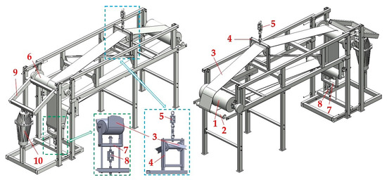
Figure 1.
3D model of a laboratory device detecting the friction coefficient in the contact surface of the conveyor belt and the driving drum lining. 1—driving drum, 2—idler φ 63 mm, 3—conveyor belt, 4, 7—idler holder, 5, 8—load cell, 6—return drum, 9—brake mechanism, and 10—electro-hydraulic device.
By moving the axis of the conveyor idler 2 (Figure 1) horizontally, it is possible to achieve a change in the wrap angle α [deg] of conveyor belt 3 on the circumference of the driving drum casing 1 for this laboratory machine.
The drive drum 1, marked by its producer as LAT216.1 [34] (with technical parameters nb = 32 min−1, M2 = 441 N·m, and Fb = 4090 N), was purchased from the company Bluetech Ltd. This drum with a diameter of Db = 216 mm is made of steel and rotated at a peripheral speed of vb = 0.37 m·s−1 in bearings pressed on a shaft with a diameter of 40 mm. The drive drum with its built-in planetary gearbox (a gear ratio ip = 29.06) uses a three-phase electric motor with the power of Pe = 1.5 kW and nominal speed ne = 930·min−1.
Conveyor belt 3 with the width B = 200 mm (does not affect the value of the friction coefficient µ [-] [28]). It is supported in the upper part of the laboratory machine by an idler, which is mounted on a steel structure 4 that can be vertically moved relative to the steel frame of the machine. Conveyor belt width B = 0.2 m was selected concerning the required amount of mean contact pressure p [Pa] (4) [33] acting between the conveyor belt and the driving drum [29].
For the mean contact pressures p [Pa] in the range from 0 ÷ 0.1 MPa to 0.7 ÷ 0.8 MPa, there are values of recommended friction coefficients µ [-] for conveyor belts with rubber overlays listed in [33] (p. 24). From the recommended values, see [33] (p. 24), for coefficients of friction µ [-], it is clear that their size decreases (for conveyor belts with cotton-based textile inserts, polyamide, and polyester) when the contact pressure p [Pa] [35] magnitude increases.
On the upper beam of the steel frame structure in 4, a strain gauge load cell 5 [36] is mounted. The eye of the bolt, which is screwed into the internal thread of the load cell sensor 5, is put on the hook of the hand chain hoist 11, see Figure 2.
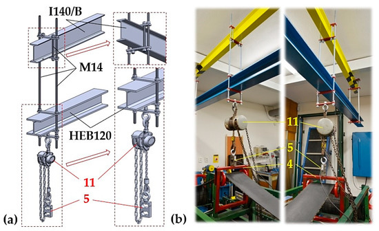
Figure 2.
Chain hoist suspended using threaded rods on cross-section beams I and HEB (a) 3D model, (b) implemented design. 4—idler holder design, 5—load cell sensor, and 11—hand chain hoist.
By shortening the length of the chain carrier of the chain hoist 11, there is a vertical shift of the idler holder 4 structure occurring, as a result of which the angles γ [deg] and δ [deg] change on the conveyor belt 3 guided in the upper run of the laboratory machine.
Conveyor belt 3 (guided around the return drum 6, see Figure 1) is pressed during the experimental tests by a wooden lining fixed by bolts on the steel structure 9 to the surface of the return drum casing 6. The steel structure 9 pressing force acting on the conveyor belt 3, which, due to the magnitude of the pressing force, is also pressed against the casing of the return drum 6, is caused by the electro-hydraulic apparatus of the EP series 10 [17,37]. Due to the friction force in contact with the conveyor belt surface and wooden lining, the speed of the conveyor belt decreases. As the pressure force of the wooden lining acting against the conveyor belt increases, the frictional “braking” force also increases linearly, which causes a reduction in the speed of the conveyor belt movement. At the moment when the frictional force in the contact surface of the wooden lining and the conveyor belt reaches the magnitude of the tractive force on the circumference of the driving drum casing, the moving conveyor belt stops (i.e., by its braking).
The laboratory machine is equipped with an electro-hydraulic device 10 [37] achieving a maximum travel height of 160 mm, a tractive force of 1900 N, and an electric motor with a power consumption of 450 W. Conveyor belt 3 in the lower run is guided around the idler mounted on the steel structure 7, which can slide vertically with movement relative to the steel frame of the laboratory device. To the lower beam of the steel frame structure, as in 7, a strain gauge load cell 8 [36] is attached.
The final laboratory device, see Figure 3 (of these basic parameters: height 1635 mm, length 2730 mm, width 780 mm, weight approximately 180 kg) equipped with load cells 5 and 8 enables the detection and subsequent recording (using DEWESoft X2 SP5 software [38]) of instantaneous values for the tensile force acting in the upper run (T1 [N]) and lower (T2 [N]) run of the endless loops of the conveyor belt 3 in time t [s] of the provided measurement. Using the known (obtained by measuring on this laboratory machine) magnitudes of tensile forces, we can calculate, according to the relationship (1), friction coefficient µ [-] at the slip point (α = β [deg]) between the conveyor belt and the driving drum.
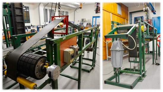
Figure 3.
Laboratory machine measuring tensile forces acting in the upper and lower runs of the conveyor belt.
From geometric dimensions (Ri [m]) and the position in the plane for (Hi [m], Li [m]) of drum axes 1, 2, and idler 3 (see Figure 4), we can analytically calculate, or measure using AutoCAD or SolidWorks software, the sizes of angles γ [deg] (5) and δ [deg] (6) for any vertical position (i.e., for H1 [m] and H2 [m]) of the idler axes 3.
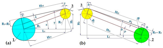
Figure 4.
Conveyor belt guided in the upper run of the laboratory machine (a) running from the idler 3 to the driving drum1 and (b) from the return drum 2 to the idler 3.
If the magnitude of angles γ [deg] (5) and δ [deg] (6) are known, we can, according to the relationship Figure 5, express the magnitude of the tensile force in the conveyor belt in the upper run of the laboratory machine by (7), which defines the magnitude of the accruing force T1 [N] of the conveyor belt 3 on the driving drum 1.
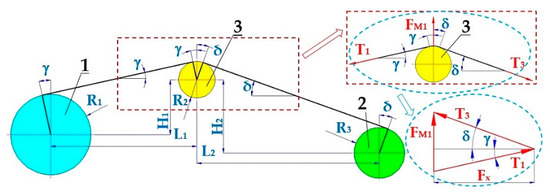
Figure 5.
Conveyor belt in the upper run of the laboratory device. 1—driving drum, 2—return drum, 3—idler mounted in a steel structure in the upper run of the conveyor belt.
Equation (7) is an approximation based on the assumption that the horizontal reaction in the bearings of cylinder 3 has been neglected.
In the return run, the tensile force T2 [N] is applied in the conveyor belt, the magnitude of which is determined by half the value of the tensioning force FM2 [N], see Figure 6a. The tension force is caused by the compression cylindrical spring 5 (see Figure 6b) of known stiffness ks [N·m−1]. The instantaneous value of the pushing force Fz [N] of the coil cylindrical spring 5 is recorded by load cell 6. The initial value of the spring compressive force 6 is adjusted by tightening the nut 7 mounted on a threaded rod 8.
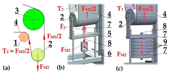
Figure 6.
Tensioning the conveyor belt in the lower run of the laboratory equipment (a) 2D sketch, (b) using the cylindrical compression spring, (c) weights. 1—transfer drum, 2—tensioning drum, 3—return drum, 4—conveyor belt, 5—cylindrical spring, 6—load cell, 7—hexagon nut, 8—threaded rod, 9—weight.
The minimum magnitude of the cylindrical spring compression 5 (i.e., the generation of compression force Fz [N]) during experimental measurements using the laboratory equipment must be such to ensure that tensile force T2 [N] in the belt of the return run in the laboratory machine reaches positive values.
Tensile force T2 [N] operating on the return run of the conveyor belt can be generated, apart from using the compression-cylindrical spring, by also using weight FM2 [N], which is suspended on the axis of the tensioning drum, see Figure 6c.
After the conveyor belt 3 (see Figure 1) is set in motion at a speed that is equal to the peripherical speed v [m·s−1] of the driving drum 1, an electric current is supplied to the electro-hydraulic device 10 [16], extending the piston (a maximum upstroke of 160 mm). The ejecting piston, mechanically attached to the steel structure of the braking device 9, changes the position of the rear part of this steel structure, which pushes the brake pad against the operating surface of the conveyor belt 3 guided over a return drum 6. In the contact surface of the conveyor belt 3 and the return drum casing 6, the frictional force increases (with the increasing pressure of the brake pad, which is caused by the piston ejecting from the electro-hydraulic device 10). This causes a gradual deceleration of the speed of the conveyor belt 3 until it stops completely (i.e., v = 0 m·s−1).
During the increase of the conveyor belt 3 compression to the return drum 6, the driving drum 1 is in operation. Due to the tractive force supplied by the drive, the tractive force is transferred by friction from the driving drum casing to the conveyor belt, with the wrap angle α [deg].
Figure 7 displays the driving drum 1 and idler 4, around which the conveyor belt is guided. From the known radii of driving drum R1 [m], idler R4 [m], and the dimensional parameters of vertical H0 [m] and horizontal L0 [m] distances of idlers axes from the driving drum axis, we can use the relationship (8) and analytically calculate the angle ν [deg].
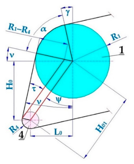
Figure 7.
Conveyor belt guided over the driving drum and conveyor idler of the laboratory machine. 1—driving drum R1 = 108 mm, 4—idler R4 = 31.5 mm.
The real size of the wrap angle α [deg] of the conveyor belt on the driving drum is difficult to measure. Therefore, it is better to calculate the magnitude of angle α [deg] using the relationship (9). Using Figure 7, we can state that the right angle (π/2 = 90 deg) is determined by the sum of angles ν [deg] (8), α [deg] (9), and γ [deg] (5).
Relationship (9) expresses the actual value of the wrap angle α [deg] for the conveyor belt operating on the driving drum when both the vertical and horizontal axes of the idlers 4 (see Figure 7) and the idler placed in the holder frame 3 (see Figure 3) are distant according to the known values from the axes of the driving drum 1.
Technical standard [33] (p. 21) defines two main types of rubber-grooved drum linings:
- (a)
- Design A—the lining thickness is less than 20 mm with an arrow or cross groove pattern. The groove depth is less than 6 mm;
- (b)
- Design B—the lining thickness is more than 20 mm. The grooving system is listed in [13,33].
The recommended values of friction coefficients µ [-] depending on the drum surface, the cleanliness of the contact surfaces, and contact pressure p [MPa] between the drum and belt with rubber overlays according to [13,33] are listed in Table 1.

Table 1.
Recommended values of friction coefficients µ [deg] for conveyor belts with rubber overlays.
At the moment of braking the conveyor belt on the return drum by an electro-hydraulic device, while the driving drum is in operation, due to fiber friction in the contact surface of the conveyor belt and the driving drum casing, the tensile force in the upper run increases and the tensile force in the returning belt run of the laboratory equipment decreases. Tensile force FM1 [N] value acting (on the conveyor idler mounted in the frame structure) in the upper run of the conveyor belt during steady running and also during the braking of the conveyor belt is detected by the strain gauge load cell 5 [36], see Figure 1. The values of tensile force FM1 [N] are recorded using DEWESoft [38] software during the time of the experimental measurements.
The magnitude of tensile force FM2 [N] in the lower run of the conveyor belt taken during the entire period of experimental testing is detected by the strain gauge load cell 8, see Figure 1, and it is also recorded using DEWESoft [38] software.
If the power of the electric motor for the driving drum is high enough, then when the belt brakes, the non-moving conveyor belt slips over the surface of the casing of the rotating driving drum. At the moment of the belt slipping over the circumference of the rotating drum casing, we can use the graphically plotted curves for measured tensile forces (FM1 [N] and FM2 [N]) to calculate the magnitude of the leaving run force T2 = FM2/2 [N] and according to (7) the size of incoming run force T1 [N]. T2 = TM2/2 [N] is an approximation close to reality since the two arms of the belt are not parallel but with an angle close to zero. By knowing the tensile force ratio of wrap angle α [deg] for the conveyor belt on the driving drum, we can use relationship (1) to calculate the value of the friction coefficient in motion µ [-].
3. Results
Experimental measurements provided on the laboratory machine (Figure 3) were carried out to obtain a sufficient number of measured values for tensile forces FM1 [N] (see Figure 5) and FM2 [N] (see Figure 6), which were occurring during braking at a speed of v [m·s−1], provided by the conveyor belt and electro-hydraulic device [37] which the driving drum [34] was rotating.
Graphical curves for measured tensile forces from the taken measurements (see Figure 8) using the mentioned laboratory device were recorded using DEWESoft [38] software. The time recording of the measured tensile forces taken by both load cells (5 and 8 see Figure 1) can be divided into 5 phases, see Figure 8.
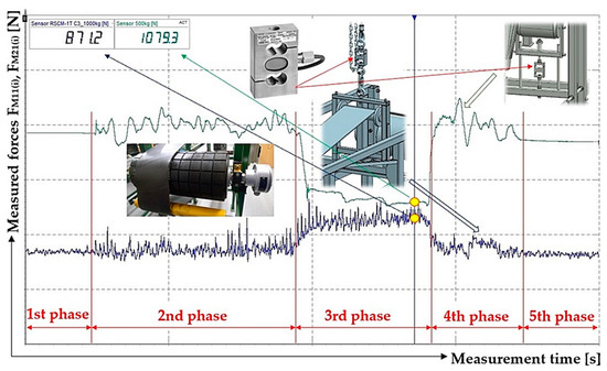
Figure 8.
Time recording of values measured for tensile forces by load cells in DEWESoft software.
The first and fifth phases represent the state when the idler holder (4 see Figure 2) is raised to the required height by a chain hoist 11 and when the conveyor belt is at rest.
The second and fourth phases present the state when the conveyor belt moves at a constant speed v [m·s−1]. The speed of conveyor belt movement can be regulated by adjusting the speed of the driving drum using a frequency converter [39].
The third stage represents the state when the electro-hydraulic device is in operation and when the wooden braking pads are pressed against the conveyor belt. Due to frictional forces acting in the contact surface of the conveyor belt, the return drum casing, and the brake linings, which are generated by the electro-hydraulic device, the movement of the conveyor belt stops, and it slips around the circumference of the driving drum casing lining. In this phase, due to the tractive force of the drive, the value of the tensile force in the upper run increases, and the value of the tensile force in the lower run of the conveyor belt decreases.
Measurements carried out on a laboratory machine, Figure 3, were done for two designs of drum surfaces: (a) a steel-smooth surface and (b) a grooved rubber surface and for the two conditions of the surfaces in contact: (a) dry clean and (b) wet clean.
3.1. Coefficient of Dry Friction—Rubber Drum Lining
For dimensions L1 = 1310 mm, H1 = 455 mm, R1 = 123 mm, L2 = 885 mm, H2 = 370 mm, and R2 = 30 mm, see Figure 4, measured on a laboratory machine (Figure 3), using the relationship (5) the angle γ = 15.31 deg was calculated.
For dimensions L0 = 130 mm, H0 = 140 mm, and R4 = 31.5 mm, see Figure 7, measured on a laboratory device (Figure 3) using relationships (8) and (9), the angles ν = 14.26 deg and α = 60.43 deg were determined.
With strain gauge load cells (5 and 8 see Figure 1) provided using a laboratory machine (Figure 3), forces FM10(i) [N] and FM20(i) [N] in the course of the 1st phase and forces FM11(i) [N] and FM21(i) [N] in the course of 3rd phase, were used for the dry and clean rubber surface of the driving drum. The values detected are listed in Table 2. From these measured values of tensile forces, using the horizontal and vertical dimensions measured on a laboratory machine Li [m], Hi [m] and radii of drums and idlers Ri [m] (see Figure 4) and angles γ [deg] (5) and δ [deg] (6) the magnitudes of tensile forces T1(i) [N] (7) and T2(i) [N] were calculated.
Table 2.
Measured values of tensile forces in the upper and lower run of the laboratory machine conveyor belt—the dry and clean rubberized surface of the driving drum.
From i = 5 repeated measurements of tensile forces that were performed under the same conditions, according to the relationship (1) used for each measured value of tensile forces, the friction coefficient values μ(i) [-] were calculated, see Table 2. In the table of critical values of the Student distribution [40] for the selected risk r = 5%, the Student coefficient tr,i [-] was determined. According to [40], the standard deviation of the arithmetic mean so [-] has been calculated for i = 5 repeated measurements. The extreme error χr,i [-] (see the last row of Table 2 and tables displayed in Sections 2.2 to 2.4) is calculated as the product of χr,i = tr,i·so [-]. The resulting value of the friction coefficient is given as the arithmetic mean μ [-] ± extreme error χr,i [-].
Time record of tensile forces FM10(1) [N] and FM20(1) [N] measured during phase 1, and forces FM11(1) [N] and FM21(1) [N] during phase 3, obtained during the measurements detected by strain gauge load cells (5 and 8 see Figure 1) [41] mounted on the laboratory machine (Figure 3) are shown in Figure 9.
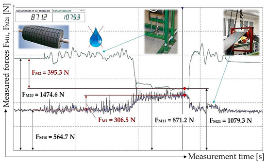
Figure 9.
Graphical record of forces detected by load cells designed using DEWESoft software.
Values of tensile forces FM11(i) [N] and FM21(i) [N] measured during phase 3 (Figure 8) carried out using the mentioned laboratory device (Figure 3), for i = 2 to 5 listed in Table 2, are displayed in Figure 10.
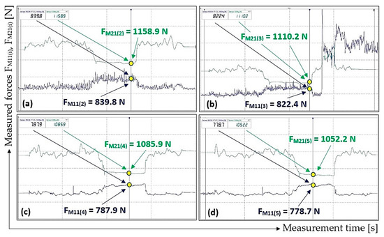
Figure 10.
Measured values of tensile forces in the upper and lower run of the laboratory device for a dry and clean surface of the rubberized driving drum casing. (a) tensile forces FM11(2), FM21(2) [N], see Table 2, (b) tensile forces FM11(3), FM21(3) [N], (c) tensile forces FM11(4), FM21(4) [N], (d) tensile forces FM11(5), FM21(5) [N].
3.2. Wet Friction Coefficient—Rubber Drum Lining
In the experimental measurements of friction coefficient measured for the wet conditions of the rubber lining on the drum casing, for identical dimensions Li [m], Hi [m], and Ri [m] provided using the laboratory device (Figure 3) of the dimensions given in Section 2.1, the identical values of angles γ [deg], δ [deg], ν [deg], and α [deg] were used.
With strain gauge load cells (5 and 8 see Figure 1) provided using a laboratory machine (Figure 3), forces FM10(i) [N] and FM20(i) [N] in the course of the 1st phase and forces FM11(i) [N] and FM21(i) [N] in the course of 3rd phase, were used for the wet and clean rubber surface of the driving drum. The values detected are listed in Table 3.
Table 3.
Measured values of the tensile forces in the upper and lower runs of the conveyor belt of the laboratory machine—the wet and clean rubberized surface of the driving drum.
Values of tensile forces FM11(i) [N] and FM21(i) [N] measured during phase 3 (Figure 8) carried out using the mentioned laboratory device (Figure 3), for i = 1 to 5 listed in Table 3, are displayed in Figure 11.
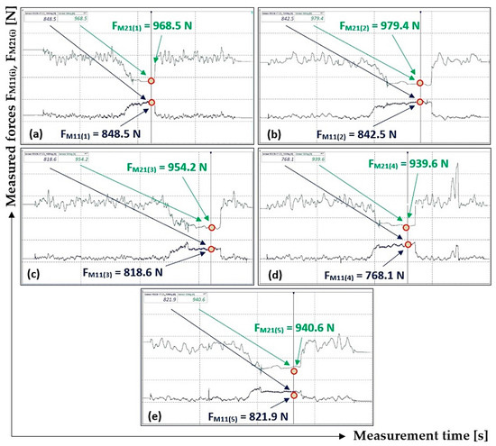
Figure 11.
Measured values of tensile forces in the upper and lower run of the laboratory device for the wet and clean surface of the rubberized driving drum casing. (a) tensile forces FM11(1), FM21(1) [N], see Table 3, (b) tensile forces FM11(2), FM21(2) [N], (c) tensile forces FM11(3), FM21(3) [N], (d) tensile forces FM11(4), FM21(4) [N], (e) tensile forces FM11(5), FM21(5) [N].
3.3. Dry Friction Coefficient—Steel Drum Casing
For adjusted dimensions R1 = 108 mm (on the driving drum casing, see Figure 12, no rubber-grooved lining of 15 mm thickness is glued) and L0 = 105 mm, which were measured using the laboratory device (Figure 3), using the relationship (5) the angle γ = 15.93 deg was calculated and with the relationships (8) and (9) the magnitudes of angles ν = 10.95 deg and α = 63.12 deg were determined.
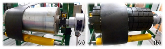
Figure 12.
Driving drum casing (a) steel smooth and (b) rubberized grooved.
With strain gauge load cells (5 and 8 see Figure 1) provided using a laboratory machine (Figure 3), forces FM10(i) [N] and FM20(i) [N] in the course of the 1st phase and forces FM11(i) [N] and FM21(i) [N] in the course of 3rd phase, were used for the dry and clean rubber surface of the driving drum. The values detected are listed in Table 4.
Table 4.
Measured values of the tensile forces in the upper and lower run of the laboratory machine conveyor belt—the dry and clean surface of the steel casing of the driving drum.
Values of tensile forces FM11(i) [N] and FM21(i) [N] measured during phase 3 (Figure 8) carried out using the mentioned laboratory device (Figure 3), for i = 1 to 5 listed in Table 4, are displayed in Figure 13.
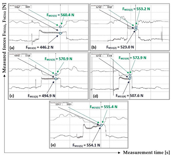
Figure 13.
Measured values of tensile forces in the upper and lower run of the laboratory device for the dry and clean surface of the steel casing of the driving drum. (a) tensile forces FM11(1), FM21(1) [N], see Table 4, (b) tensile forces FM11(2), FM21(2) [N], (c) tensile forces FM11(3), FM21(3) [N], (d) tensile forces FM11(4), FM21(4) [N], (e) tensile forces FM11(5), FM21(5) [N].
3.4. Wet Friction Coefficient—Steel Drum Casing
In the experimental measurements of friction coefficient measured for the wet conditions of the steel drum casing, for identical dimensions Li [m], Hi [m], and Ri [m] provided using the laboratory device (Figure 3) of the dimensions given in Section 2.3, the identical values of angles γ [deg], δ [deg], ν [deg], and α [deg] were used.
With strain gauge load cells (5 and 8 see Figure 1) provided using a laboratory machine (Figure 3), forces FM10(i) [N], and FM20(i) [N] in the course of the 1st phase and forces FM11(i) [N] and FM21(i) [N] in the course of 3rd phase, were used for the dry and clean rubber surface of the driving drum. The values detected are listed in Table 5.
Table 5.
Measured values of the tensile forces in the upper and lower run of the laboratory machine conveyor belt—the wet and clean surface of the steel casing of the driving drum.
Values of tensile forces FM11(i) [N] and FM21(i) [N] measured during phase 3 (Figure 8) carried out using the mentioned laboratory device (Figure 3), for i = 1 to 5 listed in Table 5, are displayed in Figure 14.
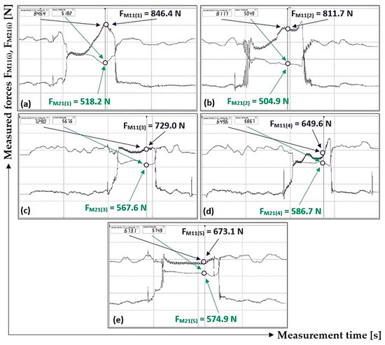
Figure 14.
Measured values of tensile forces in the upper and lower run of the laboratory device for the wet and clean surface of the steel casing of the driving drum. (a) tensile forces FM11(1), FM21(1) [N], see Table 5, (b) tensile forces FM11(2), FM21(2) [N], (c) tensile forces FM11(3), FM21(3) [N], (d) tensile forces FM11(4), FM21(4) [N], (e) tensile forces FM11(5), FM21(5) [N].
4. Discussion
The magnitude of the circumferential force transmitted from the driving drum to the conveyor belt on one driving drum of this conveyor belt depends on three factors: the belt preload (expressed by tensile force T2 [N]), wrap angle α [deg], and friction coefficient µ [-] in the contact surface of the conveyor belt and the driving drum casing. The size of the tensile force T2 [N] selected for the run leaving from the driving drum, as well as the geometric size of the wrap angle α [deg], is limited; therefore, knowledge and the proper selection of the friction coefficient µ [-] is very important for the transmission of the circumferential force.
The magnitude of the friction coefficient µ [-] acting between two bodies on a mutual contact surface cannot be directly measured. However, it can be calculated using the magnitudes of known forces T1 [N] and T2 [N] and the magnitude of friction coefficient µ [-] on the slip limit for the belt placed on the drum, using the relationship (1). Friction in the bearings of all the rolling elements has been neglected.
From the values measured for the tensile forces acting on the laboratory machine (Figure 3), the magnitudes of friction coefficients in both dry and wet conditions of the two contact surfaces were calculated. These contact surfaces are represented by a rubber conveyor belt and the rubber lining of the driving drum casing, and the friction coefficients reach higher values than specified in the standard [33], see Table 1.
The mean value of the measured friction coefficient (see Table 2), taken when the surface of the rubber lining on the driving drum was dry, reaches the magnitude of μ = 0.85, corresponding to 106.3% of the standard value. In cases when the surface of the rubber lining on the driving drum was wet, the mean value of the friction coefficient was μ = 0.43 (see Table 3), corresponding to 119.4% of the standard value.
This standard [33] does not define whether the stated values for the friction coefficients are measured as static (at rest) or dynamic (in operation) values.
The values of the friction coefficients measured on the rubber lining as higher ones in comparison with those defined by relevant standards can be explained by the fact that the surface of the rubber lining for the laboratory machine driving drum, Figure 12b, is not ideally smooth but roughened. The higher values of friction coefficients measured in wet conditions are influenced by the grooves formed around the perimeter of the rubber lining, into which the water is extruded. This water comes from the contact area between the rubber lining and a part of the conveyor belt placed on the driving drum. The higher measured values of the friction coefficients are also due to the low peripheral speed of the driving drum, which rotates at the speed nb = 17.4 min−1, compared to operating speeds [21]. Values calculated for friction coefficient (Table 2 and Table 3), acting between the rubber conveyor belt and the rubber linings in a laboratory machine, are dynamic values, which are smaller in size compared to static values.
During experimental measurements carried out on the laboratory machine (Figure 3) in our laboratory at the Department of Machine and Industrial Design, Faculty of Mechanical Engineering, VSB-Technical University of Ostrava, the pressure force acting on the conveyor belt was applied to the surface of the rubber lining (or to the steel casing) of the driving drum. Its magnitude can be expressed as the sum of actual (obtained by measurements) tensile forces T1(i) [N] and T2(i) [N]; see Table 2 to Table 4.
The mean value of the measured friction coefficient (see Table 4) when the surface of the steel casing of the driving drum is dry reaches the magnitude of μ = 0.5, corresponding to 125% of the standard value. When the surface of the steel casing was wet, the mean value of the friction coefficient measured (see Table 5) reached μ = 0.41, corresponding to 273.3% of the standard value.
From a physical point of view, the area between the dry and wet state of the contact surface cannot be determined. When the experimental measurements were carried out using our laboratory device, it was not clear how thick a layer of water was necessary to fundamentally change the friction conditions on the driving drum. An important fact obtained via the provided measurements is the knowledge that it is very difficult to define the state of the contact area precisely.
The actual values of contact pressure, calculated according to (4) for measured tensile forces T1(i) [N] and T2(i) [N] on the laboratory device, reach values of approx. p = 20·103 Pa for the rubber linings on the driving drum. These contact pressures, when compared to the contact pressure used for belt conveyors in practice (p to 0.8 MPa), are low. Under laboratory conditions, the contact pressure values for contact pressures, which show rubber conveyor belts used for belt conveyors in industry, can be difficult to achieve, as it would be necessary to apply a high value of tension force FM2 [N], see Figure 6. Even lower contact pressure values, of approx. p = 3.1·103 Pa was achieved on the laboratory machine for the steel casing of the driving drum. Higher measured values of the friction coefficient on the laboratory machine are also influenced by the low contact pressure values (values µ [-] decrease with increasing mean contact pressure between the belt and drum [27]).
The mechanism (see 9 Figure 1) bringing to rest (by applying the contact force of the wooden lining attached to the brake mechanism 9) the moving conveyor belt was not able to stop the belt with the wrap angle α [deg] against the driving drum casing. By mounting the idler 2, it was possible to change (lower) the wrap angle α [deg] for the conveyor belt on the laboratory machine driving drum. The real magnitude of the used wrap angle α [deg] for the conveyor belt on the driving drum casing (which can be taken as equal to the magnitude of the geometric angle of the wrap) significantly affects the transmission capability. The real size of the wrap angle α [deg] was calculated according to the relationship (9), which is affected by the dimensional parameters of the laboratory machine. It is necessary to draw attention to the fact that the minimal change in the size of the wrap angle α [deg] leads to a significant influence on the resulting value calculated using the relationship (1) for the friction coefficient μ [-].
The method of measuring tensile forces on our laboratory device, of which instantaneous values have been detected using strain gauge load cells and displayed in DEWESoft software, is presented in Section 3 of this paper, and their purpose is to introduce this laboratory machine (see Figure 3) on which, it is possible to practically verify the patterns of tractive force transmission by friction between the driving drum and the conveyor belt. Using the theoretical Euler (Eytelwein) relationship (1), we can determine the friction coefficient provided that a sufficient amount of leaving force (a force acting in the return run of the endless loop of the conveyor belt), ensuring the tensioning of the belt by applying a proper force, is generated.
5. Conclusions
In the case of a continuously operating conveyor device, namely the conveyor belt, the transmission of the circumferential force from the driving drum casing to the conveyor belt is implemented using friction. For the tensile forces in the conveyor belt, the Euler (Eytelwein) equation was applied for the fiber friction. The magnitude of the transmitted circumferential force from the drive drum to the conveyor belt depends on the prestressing of the conveyor belt, the angle of wrap, and the friction coefficient acting between the belt and the drum casing.
The friction coefficient acting between the belt and the drum casing varies within wide limits under operating conditions, especially for conveyors operating in open-air areas. The low value of the friction coefficient makes it difficult to start the conveyor and leads to the need to increase the wrap angle and implement multi-drum drives.
Since the friction coefficient in the contact surface of the conveyor belt and the driving drum casing cannot be measured directly, a laboratory machine was constructed on which the tensile forces can be measured and the friction coefficient calculated from them. The calculated values of the friction coefficients, given in Section 3 of this article, cannot be considered as being completely exact but only as informative values because the presented results do not take into account all the operating states under which the frictional force is transferred from the driving drum casing to the conveyor belt on real conveyors belts.
The laboratory machine presented in the article aims to outline a possible methodology, variant, and procedure, how (if the knowledge of the exact value for the friction coefficient between the belt and drum is needed) it is possible to obtain the value of the friction coefficient from the calculations based on the measured tensile forces. The calculated actual value of the friction coefficient, used for a specific type of conveyor belt and a type of driving drum casing lining, can only be considered as real if all parameters of the specific conveyor belt are taken into account during the experimental tests, i.e., conveyor belt movement speed, tensioning force magnitude, the contact pressure value between the belt and drive drum.
Author Contributions
Conceptualization, L.H.; methodology, L.H.; software, L.H. and J.F.; validation, L.H.; formal analysis, L.H. and P.N.; investigation, L.H.; resources, L.H.; data curation, L.H. and P.N.; writing—original draft preparation, L.H.; writing—review and editing, L.H.; visualization, L.H.; supervision, J.F.; project administration, J.F.; funding acquisition, L.H. All authors have read and agreed to the published version of the manuscript.
Funding
This research was funded by the Ministry of Education, Youth and Sports of The Czech Republic, Grant No. SP2023/003 and by the Ministry of Industry and Trade of the Czech Republic, Grant No. CZ.01.1.02/0.0/0.0/20_321/0024559.
Institutional Review Board Statement
Not applicable.
Informed Consent Statement
Not applicable.
Data Availability Statement
The authors confirm that the data supporting the findings of this study are available within the article.
Acknowledgments
This work has been supported by the Ministry of Education, Youth and Sports of the Czech Republic from the Specific Research Project SP2023/003 (SV3403351) and the Ministry of Industry and Trade of the Czech Republic from the Specific Research Project CZ.01.1.02/0.0/0.0/20_321/0024559 (MP342132).
Conflicts of Interest
The authors declare no conflict of interest.
References
- Antoniak, J. Theoretical basis and industrial applications of energy–saving and increased durability belt conveyors. Acta Montan. Slovaca 2003, 8, 150–157. [Google Scholar]
- Weber, M.O.; Ehrmann, A. Necessary modification of the Euler–Eytelwein formula for knitting machines. J. Text. Inst. 2012, 103, 687–690. [Google Scholar] [CrossRef]
- Konyukhov, A.; Shala, S. New benchmark problems for verification of the curve-to-surface contact algorithm based on the generalized Euler–Eytelwein problem. Int. J. Numer. Methods Eng. 2022, 123, 411–443. [Google Scholar] [CrossRef]
- Harada, T.; Hirosato, K. Non-slipping Conditions of Endless-Cable Driven Parallel Robot by New Interpretations of the Euler-Eytelwein’s Formula. In Cable-Driven Parallel Robots, Proceedings of the 4th International Conference on Cable-Driven Parallel Robots 4, Krakow, Poland, 30 June–4 July 2019; Springer International Publishing: Berlin/Heidelberg, Germany, 2019; p. 23. [Google Scholar]
- Konyukhov, A.; Schweizerhof, K.; Konyukhov, A.; Schweizerhof, K. Frictional interaction of a spiral rope and a cylinder–3D-generalization of the Euler-Eytelwein formula considering pitch. Comput. Contact Mech. Geom. Exact Theory Arbitr. Shaped Bodies 2013, 4, 413–422. [Google Scholar]
- Konyukhov, A.; Schweizerhof, K.; Metzger, A. On contact between curves and rigid surfaces–from verification of the euler-eytelwein problem to knots. In COMPLAS XI, Proceedings of the XI International Conference on Computational Plasticity: Fundamentals and Applications, Barcelona, Spain, 7–9 September 2011; CIMNE: Barcelona, Spain, 2011; pp. 147–158. [Google Scholar]
- Konyukhov, A.; Schweizerhof, K. Contact between Curves and Rigid Surfaces: Covariant Formulation and Verifications. Available online: https://www.researchgate.net/profile/Karl-Schweizerhof/publication/251230716_Contact_between_curves_and_rigid_surfaces_covariant_formulation_and_verifications/links/5ae0b2ab0f7e9b2859480447/Contact-between-curves-and-rigid-surfaces-covariant-formulation-and-verifications.pdf (accessed on 3 April 2023).
- Bulin, R.; Hajzman, M. Comparison of detailed belt-cylinder interaction model with classical belt friction formula. Stroj. Časopis J. Mech. Eng. 2019, 69, 9–16. [Google Scholar] [CrossRef][Green Version]
- Ma, X.; Pan, Y.; Shi, X. Experimental investigation of friction and slip at the traction interface of rope and sheave. J. Appl. Mech. 2018, 85, 011006. [Google Scholar] [CrossRef]
- Shi-zai, C.; Meng-gang, Y. High-precision three-dimensional finite element method for analysis of sliding cable structures. Eng. Mech. 2023, 40, 135–144. [Google Scholar]
- Gładysiewicz, L.; Krol, R.; Kisielewski, W.; Kaszuba, D. Experimentální stanovení koeficientu umělého tření pásových dopravníků. Acta Montan. Slovaca 2017, 22, 14–26. [Google Scholar]
- Munzenberger, P.; Wheeler, C. Laboratory measurement of the indentation rolling resistance of conveyor belts. Measurement 2016, 94, 909–918. [Google Scholar] [CrossRef]
- Fedorko, G.; Molnar, V.; Michalik, P.; Dovica, M.; Kelemenova, T.; Toth, T. Failure analysis of conveyor belt samples under tensile load. J. Ind. Text. 2019, 48, 1364–1383. [Google Scholar] [CrossRef]
- Krol, R.; Kisielewski, W.; Kaszuba, D.; Gładysiewicz, L. Testing belt conveyor resistance to motion in underground mine conditions. Int. J. Min. Reclam. Environ. 2017, 31, 78–90. [Google Scholar] [CrossRef]
- Rudolphi, T.J.; Reicks, A.V. Viscoelastic indentation and resistance to motion of conveyor belts using a generalized maxwell model of the backing material. Rubber Chem. Technol. 2006, 79, 307–319. [Google Scholar] [CrossRef]
- Frydrysek, K.; Cepica, D.; Hrabovsky, L.; Nikodym, M. Experimental and Stochastic Application of an Elastic Foundation in Loose Material Transport via Sandwich Belt Conveyors. Machines 2023, 11, 327. [Google Scholar] [CrossRef]
- Hrabovsky, L.; Ucen, O.; Kudrna, L.; Cepica, D.; Frydrysek, K. Laboratory Device Detecting Tensile Forces in the Rope and Coefficient of Friction in the Rope Sheave Groove. Machines 2022, 10, 590. [Google Scholar] [CrossRef]
- Krol, R.; Gladysiewicz, L.; Kaszuba, D.; Kisielewski, W. New quality standards of testing idlers for highly effective belt conveyors. In IOP Conference Series: Earth and Environmental Science; IOP Publishing: Bristol, UK, 2017; Volume 95, pp. 14–26. [Google Scholar]
- Hrabovsky, L.; Fries, J.; Kudrna, L.; Gaszek, J. Determination of the Coefficient of Friction in a Pulley Groove by the Indirect Method. Coatings 2022, 12, 606. [Google Scholar] [CrossRef]
- Euler, M.L. Remarques Sur L’effect Du Frottement Dans L’equilibre. Mem. Acad. Sci. 1769, 18, 265–278. [Google Scholar]
- Klimecky, O.; Veverkova, H.; Bailotti, K.; Muller, J. Manipuace s materiálem. Doprava V Lomech. Ostrav. 1988, 320. [Google Scholar]
- Childs, T.; Cowburn, D. Contact observations on and friction of rubber drive belting. Wear 1994, 100, 59–76. [Google Scholar] [CrossRef]
- Bartenev, G.M.; Lavrentjev, V.V.; Konstantinova, N.A. The actual contact area and friction properties of elastomers under frictional contact with solid surfaces. Rubber Chem. Technol. 1972, 45, 1094–1103. [Google Scholar] [CrossRef]
- Bechtel, S.E.; Vohra, S.; Jacob, K.I.; Carlson, C.D. The stretching and slipping of belts and fibers on pulleys. J. Appl. Mech. 2000, 67, 197–206. [Google Scholar] [CrossRef]
- Leamy, M.J.; Wasfy, T.M. Transient and steady-state dynamic finite element modelling of belt-drives. J. Dyn. Sys. Meas. Control 2002, 124, 575–581. [Google Scholar] [CrossRef]
- Leamy, M.J.; Barber, J.R.; Perkins, N.C. Dynamics of belt/pulley frictional contact. In IUTAM Symposium on Unilateral Multibody Contacts; Springer International Publishing: Berlin/Heidelberg, Germany, 1999; pp. 277–286. [Google Scholar]
- Polak, J.; Bailotti, K.; Pavliska, J.; Hrabovsky, L. Dopravni a Manipulační Zařízení II; Ostrava 2003; VŠB-Technická Univerzita Ostrava: Ostrava, Poland, 2003; p. 109. ISBN 80-248-0493-X. [Google Scholar]
- Havelka, Z.; Tuma, J. Teorie pásových dopravníků. Praha 1971, 1–249. [Google Scholar]
- Marasova, D.; Taraba, V.; Grujic, M.; Fedorko, G.; Bindzar, P.; Husakova, N. Pásová Doprava; Vysokoškolské Učebnice: Košice, Poland, 2006; p. 280. ISBN 80-8073-628-6. [Google Scholar]
- Antoniak, L. Przenosniki tasmowe. In Wprowadzenie do Teorii i Obliczenia; Wydawnictwo Politechniki Śląskiej: Gliwice, Poland, 2004; p. 388. ISBN 83-7335-266-X. [Google Scholar]
- Zur, T.; Hardygora, M. Przenosniki Tasmowe v Gornictwie; Śląsk: Katowice, Poland, 1996; ISBN 83-7164-004-8. [Google Scholar]
- ČSN ISO 5048. Continuous Mechanical Handling Equipment. Belt Conveyors with Carrying Idlers. Calculation of Operating Power and Tensile Forces; ÚNI: Praha, Czech Republic, 1994; pp. 1–15. [Google Scholar]
- ČSN 263102. Belt Conveyors. Calculation Bases. ÚNM: Praha, Czech Republic, 1988; pp. 1–48. [Google Scholar]
- Elektroválce. Available online: https://www.dopravnipasy.com/elektrovalce (accessed on 4 January 2021).
- Hrabovsky, L.; Fries, J. Transport Performance of a Steeply Situated Belt Conveyor. Energies 2021, 14, 7984. [Google Scholar] [CrossRef]
- Single Point Load Cell PW2C. Available online: https://www.hbm.cz/wp-content/uploads/B01990.pdf (accessed on 11 November 2020).
- Elektrohydraulické Ovládací Přístroje Řady EP. Available online: https://www.embrno.cz/wp-content/uploads/2021/05/P30_EMB_cz.pdf (accessed on 14 March 2022).
- Technical Reference Manual DS-NET V20-1. Available online: https://d36j349d8rqm96.cloudfront.net/3/6/Dewesoft-DS-NET-Manual-EN.pdf (accessed on 13 September 2022).
- VS-606V7 Series Instruction Manual Compact General-Purpose Inverter. Available online: https://automasjonslab.files.wordpress.com/2018/09/yaskawa-607.pdf (accessed on 24 January 2023).
- Madr, V.; Knejzlik, J.; Kopecny, I.; Novotny, I. Fyzikální Měření (In English: Physical Measurement); SNTL: Prague, Czech Republic, 1991; p. 304. ISBN 80-03-00266-4. [Google Scholar]
- Durna, A.; Fries, J.; Hrabovsky, L.; Sliva, A.; Zarnovsky, J. Research and development of laser engraving and material cutting machine from 3D printer. Manag. Syst. Prod. Eng. 2020, 1, 47–52. [Google Scholar] [CrossRef]


Disclaimer/Publisher’s Note: The statements, opinions and data contained in all publications are solely those of the individual author(s) and contributor(s) and not of MDPI and/or the editor(s). MDPI and/or the editor(s) disclaim responsibility for any injury to people or property resulting from any ideas, methods, instructions or products referred to in the content. |
© 2023 by the authors. Licensee MDPI, Basel, Switzerland. This article is an open access article distributed under the terms and conditions of the Creative Commons Attribution (CC BY) license (https://creativecommons.org/licenses/by/4.0/).