1. Introduction
While sales of electric and hybrid vehicles are expanding rapidly around the world, pointing to a future of mobility likely to be electric, automakers continue to invest in technologies that improve the performance of internal combustion engines and vehicle electric systems, yielding significant gains [
1]. This shows that conventional vehicles are still the most used worldwide and will still be so in the short and medium term, especially in emerging markets such as Brazil. Moreover, advanced electrified propulsion is being introduced to conventional powertrains, making them more complex but more efficient than ever before, not only with respect to full hybrid technologies but to in micro and mild hybrid technologies [
1,
2]. However, the speed at which combustion engines will be replaced by electric ones depends on a few factors. Government tax incentive policies associated with the requirements of regulatory agencies are the main factors that determine investments in vehicle electrification around the world. According to a survey carried out by Anfavea (Brazil National Association of Motor Vehicle Manufacturers, São Paulo, SP, Brazil) and the American consultancy BCG (Boston Consulting Group, Boston, MA, USA) [
3], the USA, Europe, and China are rapidly changing the profile of their fleets. In the period between 2020 and 2035, in the US, the share of gasoline-powered cars will drop from 88% to 2%. In Europe, the mix of 42% (gasoline) and 37% (diesel) will change to 3% and 1%, respectively. In addition, in China, the variation will be from 86% to 0% of gasoline-powered vehicles.
Considering the case of the Brazilian market, according to the ANFAVEA study, three possible scenarios for Brazil were outlined for the next 15 years, namely, Inertial, Global Convergence, and Biofuels Protagonist [
3,
4].
The first would be the “Inertial”, in which the transformation would come at the current pace, i.e., slow, without established goals, without the general organization of the sectors involved in transport and energy generation, stimulated by the isolated initiatives of companies, and without a government policy that encourages electrification.
The second, called “Global Convergence”, would be the fastest in the sense of following the movements already underway in the more developed countries.
The third is the “Biofuels Protagonist”, a path that would favor “green” fuels, but with a similar degree of electrification to the “Inertial” scenario.
Still, according to the ANFAVEA study [
3], considering the three possible scenarios described, today, electrified models account for 2% of the light vehicle sales mix in Brazil; in 2030, they may represent from 12% to 22%, and from 32% to 62% in 2035. Even in the most conservative scenario, the Brazilian market will demand millions of units of electrified vehicles until the middle of the next decade.
In this scenario, several technologies will be evaluated between 2020 and 2035, [
5,
6] and in this way, Brazil could take advantage of its skills acquired in recent decades in its use of biofuels as a source of renewable energy. Brazil is one of the largest automotive markets in the world [
5,
7] and has used ethanol, which is produced from sugarcane as an alternative fuel for combustion engines [
5,
8]. since the 1980s.
The biofuel programs make Brazil a unique country in the world, where it is possible to use technological advances in electrification together with fuels that are less aggressive to the environment [
5].
The ethanol biofuel program has been running for over 40 years and is intended to gradually replace petroleum-derived fuels with alcohol to avoid future oil crises. In the 1980s, sales of alcohol-powered cars dominated the Brazilian market, and by 1991, approximately 60% of the country’s cars were powered by ethanol [
5]. In the 1990s, the “flex fuel” system was co-designed by multinational automakers and local suppliers, allowing for the use of gasoline or ethanol or a mixture of both [
5,
9]. Currently, flex fuel cars account for 88% of passenger vehicles produced in Brazil. The country’s energy mix is predominantly renewable, with hydroelectric and wind generation being the largest sources. There is a great opportunity to combine the benefits of renewable energy with electric and hybrid vehicles [
9,
10].
In this context, the generation energy system of the vehicle, comprising the alternator, battery, starter, and electric loads, has a measurable impact on total fuel consumption, and its more efficient use associated with other technologies and biofuels can play an important role in reaching consumption reduction goals proposed by the governments around the globe [
11].
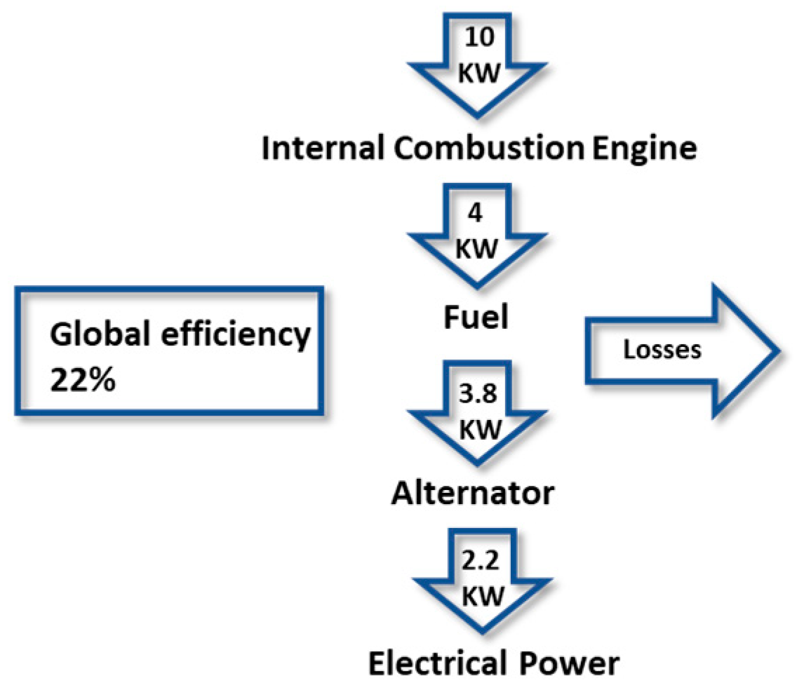
Figure 1 shows the energy conversion chain from the internal combustion engine to the alternator, and analyzing each loss in the chain is necessary to comprehend how enhancing energy system efficiency can reduce fuel consumption.
This energy conversion chain starts with chemical energy stored in the fuel and ends with electrical energy generated by the alternator. The energy content of one liter of diesel fuel is approximately 38 MJ, which is equivalent to 10 kilowatt-hours. Despite the typical engine efficiency of 40%, belt efficiency of 98%, and alternator efficiency of 55%, the overall energy conversion efficiency is only 22%. The reasons behind this low efficiency are the energy losses associated with all the energy conversion processes, including the alternator. These losses occur during the conversion of diesel fuel to mechanical energy, and then mechanical energy to electrical energy. As a result, more fuel is required to generate a given amount of electrical energy due to these energy losses. If the alternator becomes more efficient in the process of converting mechanical energy into electrical energy, less fuel is consumed by the vehicle. Alternator power demands are generally small compared to the overall vehicle, but particularly at idle, the impact on fuel cost can be measured.
Despite the potential benefits of new technologies, their evaluation typically requires a significant investment in building physical prototypes of parts and vehicles. However, this investment can be avoided by utilizing computer simulations as a substitute. The main goal of this study is to create a modeling technique that enables the integration of a vehicle’s energy system into existing hardware-in-the-loop (HIL) systems. This technique enables researchers to study and analyze existing micro-hybrid technologies and also evaluate new proposals without the need for expensive physical prototypes.
2. Literature Review
HIL, software-in-the-loop (SIL), and model-in-the-loop (MIL) systems are simulation techniques used in engineering to test complex electronic and mechanical systems in real time which can be used to validate developed solutions in new projects.
The HIL technique originates in the 1950s and 1960s, with the development of the aerospace industry and flight control systems. At that time, engineers used flight simulators to test control and navigation systems, but these simulators were very expensive and difficult to maintain [
12]. In the 1970s, electronic technology advancements and a need for more intricate control systems led to the creation of HIL systems. Initially, HIL systems utilized analog computers and simulation devices, such as resistors and capacitors, to emulate genuine systems [
12].
HIL is currently widely used in many areas such as aerospace, automotive, electronics, energy, and other industries that require complex and highly reliable systems. In this technique, a system under development is connected to a set of simulation devices that represent the environment in which the system will operate. The system is then tested in real-time, with the simulation devices interacting with the hardware of the system under development. The utilization of simulations speeds up the design process, improves quality control, and minimizes the need for physical prototypes and physical tests [
13,
14]. Conventional or hybrid vehicle testing needs the creation of electromechanical systems or full-scale vehicle prototypes, whereas simulations offer a more feasible alternative that is both cost and time effective.
Although simulations can help analyze certain aspects of a complex vehicle system, they may not provide a comprehensive understanding of all the dynamics involved. To effectively utilize these techniques, it is crucial to create virtual test models of the components, electronic control units, and the vehicle system, which can be used to validate the design. These models are then used to predict the energy efficiency of a hybrid powertrain based on simulation or experimental data [
15,
16]. Optimization of the energy management strategy is a critical step to calibrate a new vehicle during its development.
The simulations currently used, such as HIL, include good models such as the internal combustion engine and some control units, but do not have detailed models for some of the conventional vehicle electric systems, such as the alternator, lead acid battery, starter, and electric loads. The models proposed suffer a lack of accuracy [
17,
18]. From accurate models of the conventional energy system, it is possible to develop strategies for its best performance and to develop micro and mild hybrid solutions. Researchers have focused their attention of improving the efficiency and reliability of the electrified powertrain system [
13]. In this direction, the main focus of HIL developers is finding a solution for full hybrids or battery electric vehicles; there is a gap for good models requiring solutions for the inclusion of micro and mild hybrid vehicles in the conventional powertrain system [
19,
20]. The model of the complete conventional vehicle electric system can be a starting point for developing new proposals or strategies for micro and mild hybrid vehicles [
21,
22].
The integration of all the vehicle’s electronic systems with the powertrain is an important part of the vehicle validation process, and, if carried out based only on prototypes, the time for its execution is increased as well as the reaction time for possible problems and the needed corrections [
23,
24].
3. Modeling and Simulation of the Lundell Alternator
The conventional Lundell alternator is a claw pole synchronous machine used to generate an output voltage of 14 V and is still the prevalent electrical generator used in conventional vehicles and in mild hybrid applications such as BSG (Belt Starter Generators) 12 V/48 V. It has been widely used in vehicles in recent decades and it consists of a wound rotor mounted on two bearings, a three-phase star- or delta-connected stator, a six-pulse diode rectifier, and a voltage regulator [
25]. The generated AC output is rectified to a single DC voltage and then regulated to 12 V [
26,
27].
Over the last decades, significant effort has been made in developing good circuit-based models of standard synchronous machines that can be used to evaluate machine and system performance. Although it is reasonably accurate for standard machines, due to the claw-type rotor geometry and the use of concentrated stator windings, these equivalent circuit representations are limited in their ability to characterize the dynamics of Lundell machines, especially considering all the losses over the entire operating range [
28,
29,
30,
31,
32].
Various authors have utilized the finite element method to precisely determine the dynamic properties of the Lundell-type alternator [
33,
34]. Additionally, an alternative approach that involves equivalent magnetic circuits [
35] has been proposed, which is not typically available in commonly used simulation packages and is computationally intensive [
36].
An efficient and moderately complex fourth-order coupled circuit model was introduced to represent the behavior of a claw pole alternator [
36]. The model considers harmonic effects resulting from rotor salience, concentrated stator windings, corresponding slots, and magnetic saturation. Although this model is more complex than standard synchronous machine models, it provides a more precise representation of the claw pole alternator’s behavior [
31]. Thus, selecting a model for automotive applications involves consideration of the trade-off between accuracy and complexity.
In the upcoming section, there will be two distinct approaches that will be evaluated: the initial approach will involve the utilization of classical DQ coordinates; while the subsequent approach will involve a quasi-static methodology.
3.1. Alternator Model in qd Coordinates
Detailed models of the systems can be created with available simulation packages, but they are computationally intensive and unsuitable for system-level analysis due to discontinuity caused by rectifier switching. Thus, simplified models are required for effective system-level analysis, as they provide a more continuous representation of the system’s behavior and can identify critical parameters and control strategies [
36].
Figure 2 shows the power conversion chain.
To simulate the Lundell-type alternator rectifier system in an automotive application, the classical approach can be employed using
dq coordinates. However, these models are already well-documented in the literature for conventional synchronous generators. The Lundell-type alternator, known for its low efficiency, requires a more accurate representation of all its losses. The conventional models must be modified to account for the specific losses in the Lundell-type alternator [
37]. Therefore, when simulating this type of alternator, a comprehensive understanding of its losses is necessary for an accurate and reliable simulation. This will enable us to better evaluate the system’s efficiency and identify areas for improvement. Overall, a thorough analysis of the Lundell-type alternator’s losses is essential for accurate modeling and simulation of its rectifier system in automotive applications.
This approach was instigated by the author of this work [
38], in which it was based on the model in qd coordinates of a six-phase machine with two sets of arbitrarily displaced stator windings proposed by [
31,
39], without the use of damping windings. To represent all the alternator losses and to have an accurate computer simulation, the damper windings were removed, and the iron core losses can be represented as additional short-circuit three-phase windings to the stator side [
31]. The new equivalent circuit can be represented as shown in
Figure 3.
Using the
dq theory and applying Park’s transformation in Equation (1), it is possible to write the equations in the rotor’s reference frame as follows in Equations (2)–(15), where
are stator currents,
is the field current,
is the base angular frequency, λ is the flux linkage,
L is the inductance, ψ is the flux linkages per second,
x is the reactance,
is the torque in rotor reference frame,
is the inductance matrix, and
is the rotor angle.
This approach had good results [
38]; the transient response of the open loop alternator rectifier system due to the transient input of the field current and engine speed was predicted well; however, the compromise between model complexity and computational efficiency must be evaluated. The
dq coordinates model requires a long computational time to run, is complicated to implement, has limited information provided by the suppliers, and is not flexible for integration into other systems such as in HIL systems.
3.2. Quasi-Static Model
The proposed model for simulating the behavior of a Lundell alternator treats the alternator as a black box and takes in its temperature, the engine’s rotation, and the field current as inputs, as illustrated in
Figure 4 [
38]. The Simulink Lookup table function is used for interpolation, and the n-D Lookup Table block is used to map inputs to an output value by interpolating a table of values defined with block parameters.
Compared to dynamic simulations that utilize differential equations, these simulations are quicker since vehicle system models are defined as lookup tables and static equations. Using this approach presents a challenge as it necessitates knowledge of the operation and design of the component being simulated, which is frequently not disclosed by automotive manufacturers. This includes critical details such as the functioning and operation of electric vehicle/HEV technologies (including encrypted CAN protocols). Although some specifications such as motor and inverter power are typically available, they lack crucial information such as the power capacity across the entire operating range, the duration for which that power can be sustained, and the efficiency over the entire operating region. These and other essential features are required to create precise quasi-static models.
To use this approach, it was necessary to build a test bench and carry out a large number of experimental tests to cover the entire operating region of the alternator, including different temperatures. The test bench configuration includes an induction motor for regulating rotational speed, a torque transducer for measuring alternator input power, a resistance bank for simulating vehicle loads, and a 12 V lead-acid battery, as can be seen in
Figure 5 and schematically in
Figure 6. The proposed simulation in this paper was intended for an intelligent alternator, so the regulator was eliminated, and an excitation current was directly injected into the collector to allow complete control of the electrical machine.
Three tables were created for interpolation: the first provides the maximum current; the second provides the generated voltage; and the third provides the alternator input torque. All tables have as input parameters the rotation of the combustion engine, the excitation current, and the working temperature of the alternator.
Figure 7 shows the simulation proposed and
Figure 8 the interpolation table.
The model results’ accuracy was also previously validated by the author of this work [
38], showing good results. In the next section, this approach will be integrated in the existing HIL component testing set up.
6. Conclusions
Hardware-in-the-loop (HIL) simulations connect physical components to virtual environments, enabling controlled and repeatable tests and the evaluation of vehicle power systems under various conditions. To incorporate powertrain models into HIL simulations, a comprehensive understanding of system components and their interactions is necessary. HIL simulations facilitate the evaluation of power system performance, allowing for the identification of issues and optimization of system parameters. HIL-based hybridized powertrain testing was demonstrated through three case studies, accurately predicting generated voltage variation, current, and efficiency. Future work will involve exploring the integration of different technologies and conducting further testing to evaluate the accuracy of simulated results. The successful integration of the alternator model into HIL simulations presents a promising tool for optimizing power system designs and decision-making in the automotive industry.
Virtual testing systems that connect physical components to a simulated environment have emerged as a powerful tool for evaluating vehicle power systems under realistic conditions while minimizing the risks and costs associated with physical testing. These simulations enable the testing and evaluation of complex systems and subsystems in a controlled and repeatable environment, with no requirement of physical component’s presence.
To integrate vehicle power system models into these simulations, a comprehensive understanding of the system components, their interactions, and their impact on the overall performance is required. This requires the development of detailed models of various powertrain components, including engines, transmission, batteries, and electric motors, as well as the control systems that regulate their operation.
By incorporating these models into virtual simulations, engineers can evaluate the performance of the vehicle power system under a wide range of operating conditions and scenarios. These simulations can be used to identify potential issues, optimize system parameters, and assess the impact of various design choices on the overall performance and efficiency of the system.
In a recent study, an existing component testing system was utilized to evaluate the performance of powertrain systems, with a focus on incorporating new hybridized powertrains into existing vehicle platforms. Three case studies were carried out, using both real and simulated loads and batteries. The results of the simulations accurately predicted generated voltage variation, battery, and alternator currents, as well as alternator efficiency and input torque.
This approach can be applied to the controller design and simulation analysis of vehicle electrical systems, such as electrical balance, voltage regulation, and calibration, since all vehicle loads are represented, and it can be utilized to improve the performance of vehicle power systems and advance the development of hybridized powertrains.
Future work will involve exploring how various technologies can be integrated into virtual component testing systems, such as 12 V and 48 V Belt Starter Generators and other components designed for hybrid electric vehicles.

