2.1. Basic Assumptions
First, the following assumptions are made:
The flow is assumed to be adiabatic, steady, and inviscid;
The fluid is compressible and a real gas;
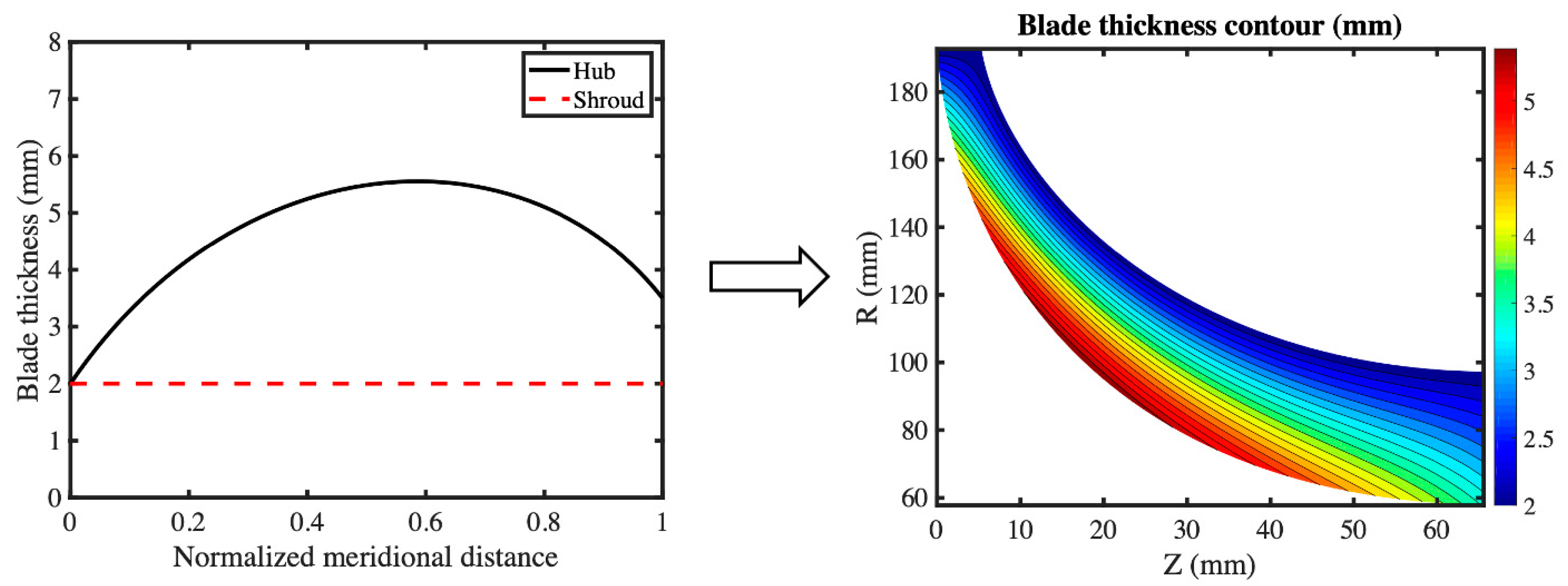
The blade is assumed to be infinitely thin with zero blade thickness;
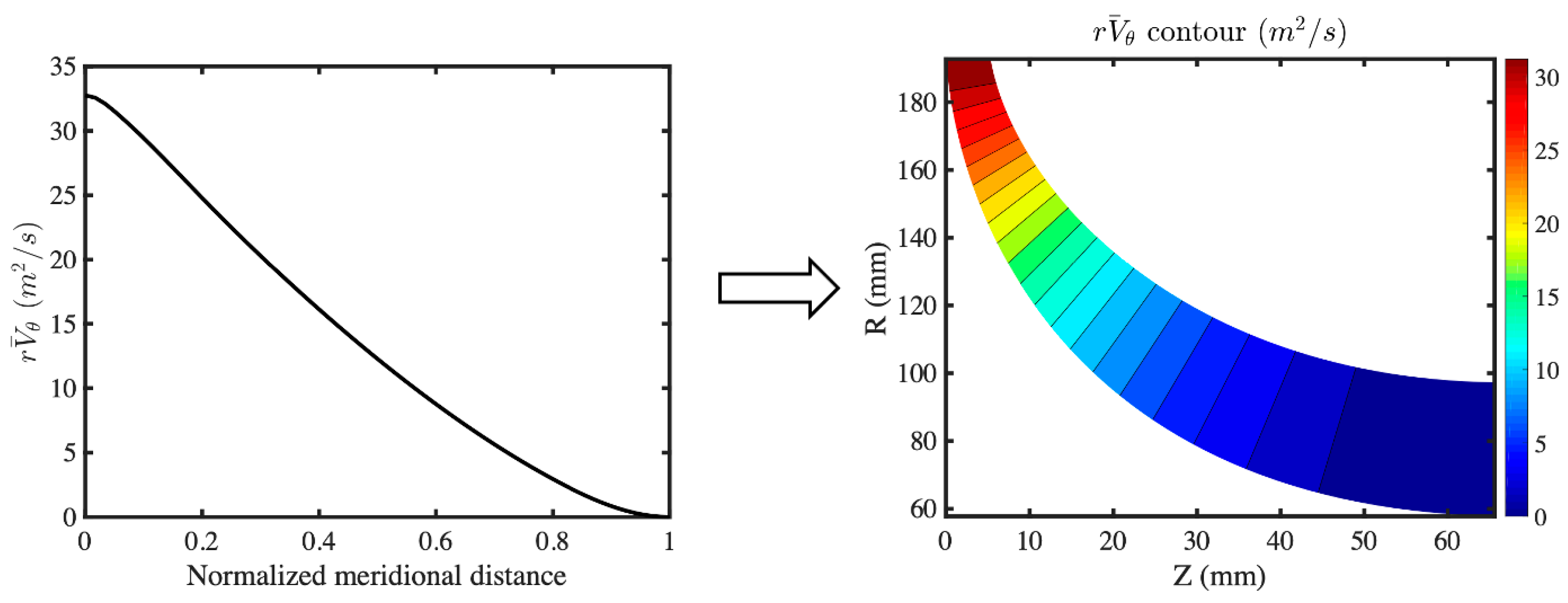
The flow near TE is free vortex, which means there is no vortex shedding after TE.
Using the first assumption with Kelvin’s theorem, it can be concluded that the only vorticity in the flow field is the blade-bound vorticity, which is bounded on all the blade surfaces. Because of the assumption of infinitely thin blades, one vorticity sheet can be used to represent the blade geometry. A blockage factor is used in the mean flow continuity equation to account for the blockage effect caused by the blade thickness.
The blade camber (or wrap angle) can be defined by:
where
α is all the blade surfaces,
r,
θ, and
z are cylindrical coordinates,
f is the blade camber, and
B is the blade number. It should be noted that
f represents the wrap angle of one single blade, while
represents the wrap angles of all the blades.
The overbar symbol ‘−’ is used to define a way of averaging along the circumferential direction, for example:
To model the periodic flow properties, a Dirac delta function is used:
It can be easily seen that the value of the delta function is infinite on the blade and remains zero anywhere else. Equation (3) can be rewritten in the form of a Fourier series (Lighthill [
33]):
The vorticity field can then be defined by Equation (5). It should be noted that the vorticity is periodic along the circumferential direction and only holds non-zero values on all the blade surfaces.
2.2. Monge–Clebsch Decomposition
The Monge–Clebsch decomposition is used to decompose the velocity field into the summation of a potential term and a rotational term (Wu et al. [
34]).
where
∇Φ is the potential term and
λ∇
μ is the rotational term. Taking the curl of Equation (6) to obtain the vorticity:
One of the Clebsch variables can be assumed to be
α. Therefore, Equation (7) can be rewritten as:
The mean vorticity field
can be obtained by taking the circumferential average of both sides of Equation (8).
Taking the circumferential average of the velocity curl to obtain the mean vorticity
:
By comparing Equations (9) and (10), it can be easily seen that:
Equations (5) and (9) can then be rewritten as:
A periodic sawtooth function
can be defined by Equations (14) and (15).
Using Equations (12), (14) and (15), the absolute vorticity field
can be written in the following form:
The velocity field
can then be expressed by the following equation.
The velocity field can also be expressed by the summation of a mean term and a periodic term.
Comparing Equations (17) and (18), the equations for the mean flow velocity
and the periodic flow velocity
can be obtained.
where
is the mean flow potential function and
is the periodic flow potential function. The last terms on the RHS of Equations (19) and (20) are equal to zero in the inlet and outlet regions since the flow is irrotational.
2.5. Periodic Flow Equations
To solve the periodic flow equation (Equation (24)), we would first like to obtain the equation for the potential function for the periodic flow
. Take the divergence of Equation (20) and substitute Equation (24), and we can get:
where the first two items on the RHS remain zero in the inlet and outlet regions, the last two items on the RHS require the calculation of the full 3D velocity field and density field. Due to the fact that the flow is periodic along the circumferential direction, it is possible to express the potential function for the periodic flow
in the form of a complex Fourier series.
where
is the Fourier coefficients of the potential function for the periodic flow
. The periodic potential function
can be further approximated in the form of a truncated IDFT:
where
is defined by Equation (39) and its value is the tangential coordinate of grid points in the tangential direction. The total number of grids is
N and the spacing between grids is
∆θ. has been chosen to make the function
space equally and periodically.
Using Equations (36), (38)–(40), the periodic flow potential function can be expressed in the following form:
where
is the Fourier coefficient of
. The terms when
n = 0 need to be neglected for the solution of the periodic flow since they represent the Monge–Clebsch formulation of the mean flow equation. Therefore, Equation (41) becomes:
where
is defined as:
Since the periodic flow potential function is a real function
, its Fourier transform satisfies the following equation:
where * denotes the complex conjugation and only half of the frequency spectra in Equation (42) need to be solved.
In order to solve Equation (42) for , boundary conditions need to be applied to the four boundaries of the physical domain, including the hub wall, the shroud wall, and the upstream (inlet) and downstream (outlet) boundaries.
The periodic velocity
should align with the hub and the shroud walls, which can be expressed by:
where
is the unit vector that is perpendicular to the hub or the shroud.
Substituting Equation (20) into Equation (45) and using Equations (15) and (37), the hub and the shroud boundary conditions for the periodic potential function can be obtained:
The flow is uniform at the far upstream and far downstream boundaries, which implies that the periodic velocity vanishes as the flow approaches the upstream/downstream boundaries. This condition can then be expressed in the following form:
The periodic velocity
is computed by using the IDFT (inverse discrete Fourier transform) of Equation (20).
2.6. Calculation of Thermophysical Properties
The thermophysical properties of any real gas can be obtained by calling the NIST REFPROP Fortran subroutine [
35] or CoolProp C++ library [
36] with any two known thermodynamic properties. The inlet total enthalpy
and inlet entropy
can be obtained from the given inlet total pressure
and inlet total temperature
. The entropy remains constant throughout the whole flow domain since the flow is inviscid and isentropic.
The rothalpy, which is defined by Equation (49), is conserved along any streamline in a steady adiabatic flow.
where
is the static enthalpy,
is the relative velocity,
is the blade speed, and
is the rotational speed. The inlet rothalpy can be calculated based on the inlet total enthalpy
and the inlet
value. The total enthalpy value
and static enthalpy
at other locations rather than the inlet can be calculated from the constant rothalpy value
I and known
or relative velocity
at that location. Using the known entropy
and enthalpy
(
) with REFPROP or CoolProp, other fluid properties, including density
, pressure
and temperature
, at any location can be obtained. It should be noted that all the properties discussed in this section are circumferentially averaged values, which means they are functions of
and
. The static enthalpy jump across the blade can be calculated from Equation (50).
where
is the static enthalpy on the blade pressure surface,
is the static enthalpy on the blade suction surface and
is the mean blade surface velocity. The mean static enthalpy is known, and it is equal to the mean of
and
. Using Equations (50) and (51),
and
can be obtained. Similarly, using the constant entropy, the blade surface pressures
(static pressure on the pressure surface) and
(static pressure on the suction surface) will be obtained.
The 3D enthalpy field
can be calculated using Equation (49) using rothalpy
I and the 3D relative velocity field
The 3D density field
can then be obtained from the constant entropy and
using REFPROP or CoolProp. The Fourier transform of the natural logarithm of the density field is computed by the following equation once the density field
is available.
Taking the IDFT of we can get the derivative of in the tangential direction. Similarly, to get the axial and radial derivatives of we need to take the IDFT of the corresponding derivatives of
can be computed based on the derivatives of and the relative velocity field . The Fourier transform of is calculated using Equation (43) to obtain . The 0th component of Equation (43) which is equivalent to will be used in Equation (28) to calculate the artificial density .


