Abstract
The use of innovative mobile vehicles with increasingly advanced mechatronic aspects in the agricultural sector is becoming, in recent years, a stimulating field of research and comparison. In particular, the problem addressed in the present work refers to improving the locomotion of mobile vehicles on agricultural terrain by reducing the soil damage and improve the overall performance. Agricultural vehicles generally use tracks and wheels for locomotion; the main difference between the two systems is the contact area with the ground and, consequently, the pressure distribution. The present work presents a new reconfigurable agricultural vehicle that can switch from one locomotion system to another, choosing the suitable configuration according to the terrain conditions. All the mechanical and electronic aspects of the prototype developed are analyzed together with an in-depth analysis of the management of the innovative functions through a user-friendly graphical interface able to control the vehicle.
1. Introduction
In the last decade, the agricultural field has seen a significant increase in mechanization and technological solutions, ranging from monitoring agronomic parameters using field sensors to robots and machinery for field operations, as detailed in [1]. For some types of crops, it is possible to create ad hoc structures in highly mechanized greenhouses, as in [2,3,4], where robots are used for harvesting crops like tomatoes, apples, or strawberries. In other cases, it is necessary to intervene on existing plantations, as in [5], where a smart solar fertigation system is installed in a vineyard to optimize the use of fertilizers. One of the drawbacks of this mechanization is the increase in the size of the machinery [6], which has led to detrimental effects on the environment [7,8].
A factor of interest for the farmers is the soil quality, which directly impacts productivity and soil maintenance costs. It is well known that the use of heavy machinery has caused progressive land degradation, and several studies have been carried out to quantify this damage [9,10,11].
As a result of this altered soil state, farmers experience a loss of production and higher soil maintenance costs [12]. Moreover, there are correlated environmental issues, such as the loss of water and soil erosion [13].
Compaction and distortion are the mechanisms by which vehicle traffic in the field damages the soil. The first is the result of the normal pressure exerted at the contact patch, which causes a compression of the soil pores and reduces their volume. The shear forces cause the distortion of the soil during the vehicle motion, which destroys the pores by a constant volume displacement [14]. Without a proper amount of pore space, the soil health is compromised.
The most common running gears with which agricultural vehicles are equipped are tracks and wheels. Given a tracked and a wheeled vehicle comparable in size, their main difference will be in the contact area at the ground. Tracks provide a lower soil compaction because of the lower pressure distribution over a larger area but higher soil distortion due to the higher traction force and the peaks of pressure under the rollers [15]. Instead, wheels have a smaller contact patch and cause higher compaction but are also more agile and cause less distortion, especially during the turning maneuvers. Reducing the contact area sliding during the skid-steering maneuvers requires lower torque and energy consumption. In the literature, there are examples of systems able to change the contact area for improving the steering maneuvers, as in [16], where an eight-wheeled vehicle has a mechanism for lifting one or two pairs of wheels. Vehicle sinkage should also be considered if the soil is highly deformable. The bulldozing effect during the turning maneuver might make a tracked system preferable, despite the longer contact patch.
The different contact area also impacts tracked and wheeled vehicles’ traction performance and energy consumption. If the soil has cohesive properties (i.e., contains clay), a larger contact patch ensures a higher traction force [17], while on frictional soils, a higher normal stress can increase the soil strength and might lead to a higher draught. Moreover, the volume of soil deformed is the main contribution to the running gear rolling resistance. If the contact area is small, we can expect a high sinkage and rolling resistance on highly deformable soil. Conversely, a large area would reduce the sinkage.
To combine the benefits of wheels and tracks and adjust the contact area based on the soil conditions, we proposed a locomotion system to change the contact patch [18], and we realized “Hadrian” a new wheel/track reconfigurable vehicle. The vehicle is equipped with a locomotion system that can switch between a wheeled and a half-tracked mode by partially lifting the tracks’ idlers and leaving only the sprockets in contact with the soil to have a wheel shape interacting with the ground. This concept is depicted in Figure 1.
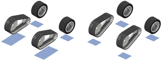
Figure 1.
Concept of the reconfigurable locomotion system. The contact area is adjusted based on the track’s configuration.
Such a system aims to minimize soil damage during farming operations and adapt to vehicle performance (traction, rolling resistance, and steering torque).
As a testbed for our system, we selected the vineyard, a good example of a field experiencing soil damage [13], especially during the harvesting period, when the farmers enter the field with heavy tractors, regardless of the soil conditions. Our test fields are the training systems used in Italy, one of the countries with the highest production of wine in the world [19], where innovative systems for the soil damage issue are required. Hadrian aims to transport the grape in the vineyard during harvesting, by avoiding using tractors. The vehicle will have to decide the locomotion mode autonomously based on proprioceptive sensors’ data (e.g., motors’ velocity and current) and exteroceptive sensors’ data (e.g., soil moisture sensors in wireless communication with the vehicle, Figure 2). Similar strategies are adopted in other works, as in [20], where exteroceptive and proprioceptive sensor data are used for terrain estimation, improving the mobility of a mobile base.
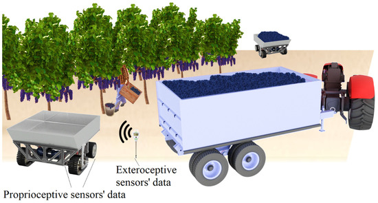
Figure 2.
Vehicles operating in the field by using proprioceptive and exteroceptive sensors’ data.
Implementing robotics in agriculture and beyond has to consider ease of use. The final user will probably not be a technician, and an easy interface becomes an essential tool for the diffusion and acceptance of new machinery. For this reason, we developed a straightforward user interface to control Hadrian remotely. Although a final version of the vehicle will be able to decide autonomously the locomotion mode based on the soil conditions, we can expect the navigation to be still performed or supervised by a human operator because of the complexity of the environment and the presence of humans in the field.
In this paper, we provide a detailed description of the vehicle and the solution adopted for its realization, specifically focusing on the system architecture and user interface developed for its control. First, we will briefly describe the environment in which the mobile base will operate and how this affects the overall size. Then, we will describe the mechanical and electrical systems, and finally, we will show in detail the user interface we developed for the easy remote control of the vehicle.
2. Materials and Methods
2.1. Reconfigurable Grape-Transporting Vehicle
2.1.1. Environment and Relative Constraints
The vehicle’s overall size is decided based on the environment in which it will operate. Since Hadrian is meant to transport grapes during the harvesting period, we have considered the sizes and characteristics of the vineyards. Several types of training systems are used worldwide: head/can, cordon/cane, head/spur, and cordon/spur [21]. The vines are usually placed in rows, leaning on steel wire structures that guide their branches.
The distance among the trees is decided based on the agricultural machinery used in the field. This distance is about 2 m, allowing the pass of tractors.
Because the vehicle must operate in the field with the people collecting the grapes, we need to keep a marginal distance between the vehicle and the people. We assume the vehicle’s size is 1.3 m × 1.3 m square. The maximum weight (including the payload) is 400–450 kg, assuming a grape payload of a maximum of 200 kg.
2.1.2. Running Gear’s Size and Traction Motors
The running gear’s size, summarized in Table 1, is a trade-off among soil damage, performance, and weight.

Table 1.
Running gear’s size.
We have conducted field experiments in a vineyard and FEM analyses of a single wheel as the size changes [22] and of a track [18] to evaluate the effect of different contact areas in terms of sinkage, rolling resistance, and pressure exerted onto the soil. Unlike the wheel, a track is a much more complex system to analyze and simulate because of the flexible chain and peak of pressures caused by the rollers, as we further discussed in [23].
We tested the rolling resistance and sinkage of our designed track module in a soil bin facility built at the Kyushu Institute of Technology [18]. We have mixed clay, silt, and sand in the percentages of 20%, 40%, and 40%, respectively, to obtain loam soil [24] with the frictional and cohesive properties typical of agricultural soil. Then, we carried out several pull-tests in which the track was mounted to a frame, loaded to 100 kg, and pulled for 2.5 m at a constant velocity by a walking tractor through a steel wire. The steel wire was attached to a force gauge sensor to measure the rolling resistance. We tested on different soil conditions: firm, soft, and wet saturated. In Figure 3, some of the test results are shown. As expected, the highest rolling resistance is obtained for the case of deformable soil (soft and wet), although the mechanism of soil deformation in the two cases is different. In soft conditions, the soil contains a higher fraction of pore space, which undergoes a compaction and volume reduction during the track pass. In saturated wet conditions, the pores are filled with water, making the soil incompressible and leading to deformation by distortion. We have a significant volume of deformed soil and a corresponding high rolling resistance in both cases.
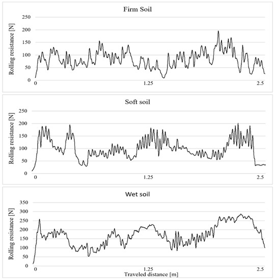
Figure 3.
Some of the pull test results carried out with the single-track module.
The results of the pull tests have been used to select the four traction motors after assuming a maximum velocity of 0.5 m/s, comparable with that of a human being walking in the field.
The DC motors selected are BLV620K100S for the front tracks and BLV510K100S for the rear wheels, developed by Oriental Motor. The BLV620K100S has a maximum torque of 52.7 Nm (1–30 rpm) for a rated power of 200 W. The BLV510K100S has a maximum torque of 27.4 Nm (1–30 rpm) for a rated power of 100 W. We expect the tracks to “support” the wheels in more difficult soil conditions (i.e., wet saturated), in which a high sinkage and high rolling resistance may cause the wheels to be stuck. In such a situation, the vehicle is supposed to switch to track mode, reducing the weight sustained by the wheels and providing the traction force to move the vehicle.
2.1.3. Mechanical Design
To describe Hadrian’s mechanical solution, we can divide the vehicle into three main groups, all mounted to the chassis: rear axle, front axle, and switching mechanism. Figure 4 shows the full vehicle and the three main groups.
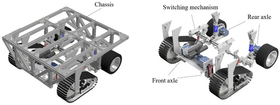
Figure 4.
Hadrian’s overview and main subsystems.
The rear axle consists of two wheels connected to the chassis through a longitudinal trailing arm suspension system. This type of suspension system has the advantage of being simple and compact. The trailing arm consists of welded steel parts, as described in Figure 5. Each wheel has a traction motor directly connected to the wheel hub. This configuration saves space onboard, leaving room for the batteries and the electrical system components at the vehicle’s rear inside the chassis. In Figure 6, the wheel system is shown in detail.
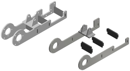
Figure 5.
Welded parts in the trailing arm of the wheel suspension system.
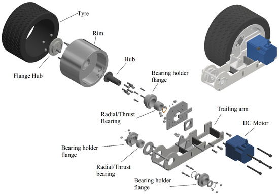
Figure 6.
Wheel group’s components.
The reason for having the wheels at the rear is that, while moving, the front running gears compact the soil, making the conditions more favorable for the rear running gears. Since the wheels cannot adjust their contact patch, having them on the rear side is more convenient. In addition, by having the sprockets facing the moving direction, we ensure that the contact shape still resembles a wheel when the vehicle is sinking, avoiding contact between the lifted portion of the track and the soil. The two reasons explained here are depicted in Figure 7.
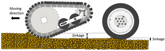
Figure 7.
Tracks at the front axle improve the soil conditions for the wheels.
The track system module was designed and realized from scratch using a steel chain with mounted attachments. A U-shaped aluminum channel and a rubber lug are fixed on each attachment by bolts and glue. The chain is connected to two gears, a sprocket, and an idler. The sprocket has a larger diameter than the idler to facilitate the wheel mode configuration when the idler is lifted. A more detailed description of the track module design can be found in [18,23].
Unlike the rear axle, the traction motors of the front axle are positioned within the chassis. The traction motor drives the sprocket gear through a chain coupled with two sprocket gears, and the transmission ratio is 1. Each sprocket gear is rigidly connected to the chassis by a pair of links. The idlers are connected to the switching mechanism by a shock absorber. Two thrust bearings mounted in O-configuration support one end of the driven shaft. Figure 8 shows the design solution adopted for the front axle. The triangular elements connected to the tracks increase the system’s overall stiffness during the turning maneuvers, when the tracks experience lateral forces. In Figure 9, the assembled wheel group and track group are shown.
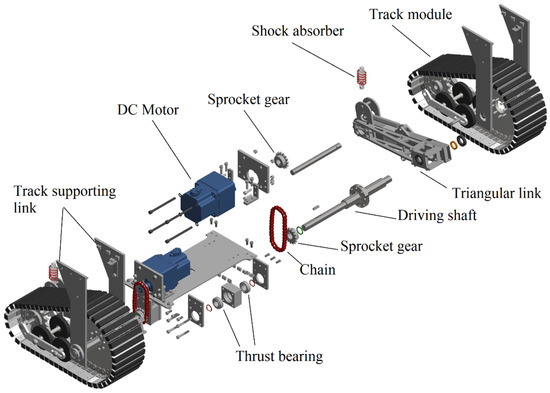
Figure 8.
Front axle’s components.
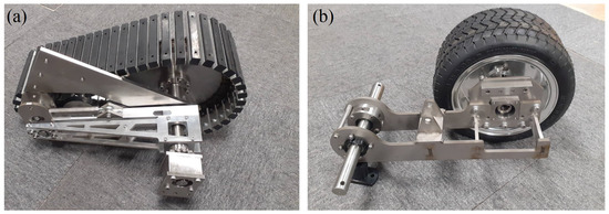
Figure 9.
Track group (a) and wheel group (b).
The last group to be described is the switching mechanism. This is a Scott Russel linkage, which converts the horizontal displacement of an electro-hydraulic actuator (EHA) into a vertical linear movement of the idlers. The mechanism consists of an EHA connected to a shaft (S1) with two bearings mounted at its ends. The bearings are inserted into two parallel linear guides. The shaft is coupled with the longest link of a scissor mechanism where the long link length is double that of the short one. A revolute joint connects the middle of the long link to one end of the short link. The other end of the long link is coupled with a second shaft (S2) connected to the idlers’ shock absorbers, as shown in Figure 10. The EHA displacements cause S1 to move along the linear guide and close or open the scissor mechanism to lift or lower S2 and the shock absorbers connected to the track modules.
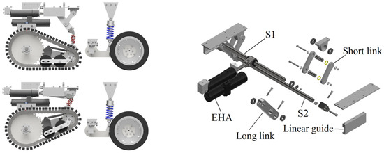
Figure 10.
Switching mechanism configurations and components.
The relation between the horizontal displacement of the EHA and the vertical displacement of the idlers is evaluated as h = b(x) × tang(α), where b = bmax − x, and bmax is the maximum distance between the roller shaft and the revolute joint of the short scissor link, and α is the angle between scissor’s links and the horizontal, as in Figure 11a. We selected the desired vertical displacement of the idler to be in the range of 100–150 mm. With this displacement, we can ensure that, while in wheel mode, the shape in contact with the ground is circular, as if it were a wheel. Figure 11b provides the static analysis of the mechanism. The number 0 indicates the chassis, 1 is the actuator, 2 and 3 are the long and short scissor links, respectively, and 4 is the linear guide. Fa is the actuator force, R the reaction force on the link and Fs the force on the idler. As can be seen from the static analysis, small values of the angle α in track mode would require a high actuator force and a higher reaction force on the links. In wheel mode instead, the actuator only lifts the idler, and relatively small α angles can be accepted. The mechanism synthesis is a trade-off between the space available inside the chassis, the desired vertical displacement, and the necessity to avoid small angles. In the final design, the α angle in track mode is 53 degrees.
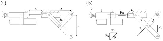
Figure 11.
(a) Relation between EHA stroke and vertical displacement. (b) Static analysis.
The EHA selected is the mini motion package MMP3-B1A100BA-GH, developed by KYB corporation, whose stroke is 0–100 mm, with a total minimum length of 280 mm and a maximum length of 380 mm. The maximum force is 5800 N, with a piston pulling velocity of 33 mm/s and a pushing velocity of 19 mm/s. Although this application’s maximum force is oversized, we preferred the Mini Motion Package because of its robustness, reliability in dirty outdoor environments, and capacity to act as a rigid link once the desired position is reached. These kinds of actuators are often used on agricultural machinery, for example, for adjusting the position of a plowing machine mounted behind a tractor.
An alternative solution we considered is using a lead screw mechanism driven by an electrical motor. Eventually, we preferred to adopt the EHA because of its higher robustness, especially under dynamic loads.
3. Results
3.1. Mechanical Final Design
The three main groups previously discussed are connected to the chassis, which consists of a ladder frame made of squared aluminum bars connected through triangular brackets. Wherever possible, the sections of the chassis have been triangulated by using diagonal elements to improve the stiffness, avoiding rectangular arrangements of bars, which would have low stiffness, especially when subjected to torsional loads [25]. The final assembly of the vehicle is shown in Figure 12, and Figure 13 shows the vehicle in the field.
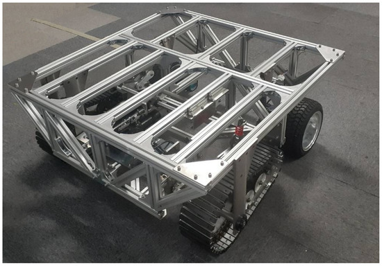
Figure 12.
Final assembly of the vehicle.
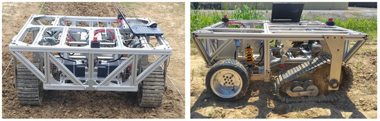
Figure 13.
Final vehicle while operating in the field.
The total weight of the vehicle without any payload is 237.5 kg. The weight distribution has been measured using a weight scale, as in Figure 14, and those measurements have been used to locate the center of gravity. In wheel mode, the weight measured is 65.5 kg and 69 kg for the left and the right tracks, respectively, and 52.5 kg and 50.5 kg for the left and right wheels, respectively. Although the track mode’s weight distribution is measured similarly, the result depends on the EHA final extension and the characteristics of the shock absorber, as detailed in our previous work [23]. With a maximum extension of the EHA (100 mm), the vertical load on the wheels becomes 31.5 kg and 33.5 kg for the left and right wheels, respectively. Future works will investigate the effects of different EHA extensions and weight distributions in a real environment. The main characteristics of the vehicle are summarized in Table 2.
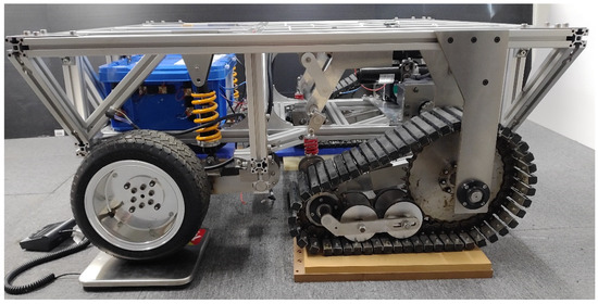
Figure 14.
Weight distribution measurement by weight scale.
Table 2.
Vehicle’s main specifications.
3.2. Electronic System Final Design
In Figure 15, the flowchart of Hadrian’s power system is provided. This includes two Li-ion batteries of 25.2 V for the four brushless DC motor driving tracks and wheels and a DC–DC converter from 25.2 V to 12 V for supplying energy to the electro-hydraulic actuator (EHA). The vehicle is equipped with a microcontroller ESP32, which has Wi-Fi integrated, used for receiving the soil moisture information from the field. The ESP32 microcontroller (receiver) is connected to a PC by USB. The relay and UART/RS485 transceiver is powered through an ESP32 (receiver) with 5 V. Each soil moisture sensor in the field (three in the example of Figure 13) is connected to a separate ESP32 (transmitter) in wireless communication with the ESP32 onboard the vehicle. Mobile batteries of 5 V power the moisture sensors. The final number of soil moisture sensors will depend on the size of the field and the expected soil moisture variability.
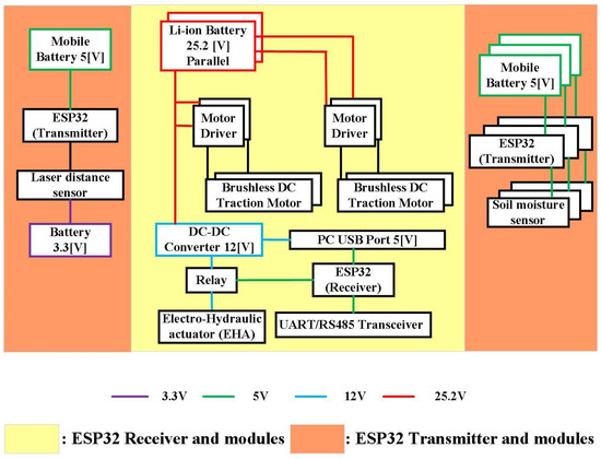
Figure 15.
Vehicle power system.
In our preliminary tests, we had the vehicle moving on straight lanes, and the slip of wheels and tracks is evaluated by using a laser distance sensor located at the end of the lane and pointing to a flat black panel mounted on the front of the vehicle. With the laser distance sensor (LDS), we measure the vehicle position (the distance from the sensor at the end of the lane), and we can estimate the moving velocity. By monitoring the motors’ rotational velocity provided by the encoders, we evaluate the slip i as i = (wr − V)/wr, where w is the angular speed measured by the encoders, r is the wheel’s radius, and V is the estimated vehicle moving velocity.
The laser distance sensor is connected to an ESP32 (transmitter), and a battery of 3.3 V powers it. The LDS is only a temporary solution for the preliminary tests because it’s simple and cost-effective. In the future, we will adopt a GPS or DGPS.
3.3. System Architecture and User Interface
A user interface has been developed for easily operating the vehicle. We first describe the system’s architecture, Figure 16, to understand how this interface works.
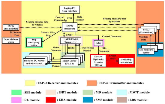
Figure 16.
Hadrian’s system architecture.
Hadrian is equipped with a laptop PC from which it can be operated using the user interface. As explained in Section 4, a microcontroller ESP32 receives the soil moisture information from the ESP32 transmitters connected to the sensors in the field. The ESP32 is also interfaced with the four motor drivers, the EHA, and the emergency button on the vehicle to stop all the motors in an emergency. The information about the moisture will be used, together with proprioceptive sensors’ data, to autonomously assess whether the locomotion mode should be wheels or tracks. At first, we will conduct a series of tests on different soil conditions (firm, soft, wet saturated) and with different payloads, and the soil damage will be assessed by our group. The compaction will be evaluated by manually measuring the Cone Index [26] and the ruts’ depth, and the distortion by using image processing and comparing the soil displacement before and after the vehicle passes. We will use these data to compare the two locomotion modes and assess the best one in the various cases. The measurements and our assessment will represent the teaching data for the design of the controller. At the same time, we will measure the motor torque, the current, the vehicle’s slip, and the soil moisture during each test. For DC motors, when the vehicle is moving at a constant velocity, the motors’ torque is proportional to the rolling resistance, which is directly related to the soil deformation [26] (in particular to the sinkage). Soil distortion depends on the shear forces exerted onto the ground, and these depend on the load distribution at the contact patch, the torque, the slip, and the soil state. A neural network-based controller will be trained with the experimental data to autonomously assess the best contact area, depending on the operating conditions. For example, during a supervised learning phase, the neural network will learn to assign a locomotion mode to a certain combination of proprioceptive and exteroceptive sensors’ data. Once the network is properly trained, we will test its performance to choose the locomotion mode on soil conditions different from the one used for the teaching phase. As the field tests are still ongoing, the design of such a controller represents the next step of this research.
The locomotion mode can also be decided manually by the user, and a switch relay controls the EHA. The traction motors use the RS485 protocol, and the UART/RS485 converter communicates with the ESP32.
In Figure 16, the system components are grouped into modules depending on the function. The SEB is the stop emergency button, U/RT is the UART/RS485 transceiver, MD is the module consisting of the motor drivers, MW/T module is the mechanical connection among motors and running gears (wheels and tracks), RL is the relay, EHA module is the electro-hydraulic actuator connected to the switching mechanism, and the SMS module consists of the soil moisture sensors. Finally, the LDS is the laser distance sensor module.
The user interface has been developed using Visual Basic 2022 [27], whose toolboxes allow for the easy implementation of the required functions. Through the interface, we want to send commands to the ESP32 to control the velocity and direction of the four traction motors and extend or shorten the EHA while monitoring the motors’ torque and running gears’ slip. The main blocks are “Button”, “TexBox”, “Chart”, and “SerialPort”. These are responsible, respectively, for operating the scan port and sending commands from visual basic.NET to the controller, displaying the sensors’ values, displaying the graphs of sensors’ values in a chart, and creating a serial port component for the synchronous and event-driven I/O to access serial driver properties. Additional blocks are used for adding labels and pictures to the graphic interface. The designed GUI is shown in Figure 17.
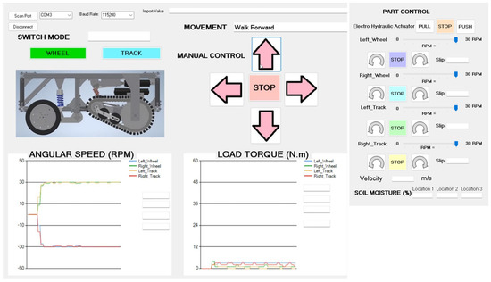
Figure 17.
The graphical user interface for operating the robot.
The buttons “WHEEL” and “TRACK” allows the user to decide on the locomotion system. The relay controls the direction to extend or shorten the piston’s position. When the “WHEEL” button is pressed, the actuator shortens until it reaches the shortest length (zero position). When the “TRACK” button is pressed, the actuator extends until it reaches the maximum extension. The image of the vehicle is used to confirm the locomotion system in use, and the switch must take place with the vehicle at a standstill. The operator must press the “Stop” button before switching the mode to ensure the vehicle is not moving. To tune the maximum possible extension of the EHA, we placed on the chassis two position switches. In particular, the shaft driven by the EHA can activate the position switches and stop the piston’s extension when the extension of the EHA is the one decided by the position of the switches (in our preliminary tests, we used 80% of the stroke). The user manually adjusts the position of the switches before using the vehicle.
Since the sprockets are connected to the motor, while the idlers can rotate freely, only the idlers rotate during the switch. This prevents the track belt from sliding onto the soil during the switch, which would cause additional forces to be sustained by the EHA and soil damage. The four arrows allow the user to decide the direction of movement. The traction motors receive a velocity input decided by the user. A velocity input is sent to wheels and tracks when the forward or back arrow is pressed. The input velocity for the front and back axles is different since the rolling radii of wheels and tracks are not the same. When an input velocity is set, we can monitor the slip of each running gear and adjust the velocity accordingly. This is possible by using the “Part Control”. The “Part Control” controls each actuator individually by selecting the rotation direction and velocity. The arrow buttons indicate the rotations’ directions, while the stop buttons can stop the corresponding running gear. The interface also allows us to display in real-time the angular velocity of each running gear and the torque exerted by every single motor. In the case of EHA, the “PULL” and “PUSH” allow the user to decide the actuator’s extension.
The vehicle uses the skid-steering to turn. The turning maneuver is carried out with the vehicle at a standstill. When the left or right arrow is pressed, the left and right side running gears spin in opposite directions, causing the vehicle to rotate. Because the skid-steering might require a high torque, especially on soft soils, we set the velocity to a maximum of 15 rpm to not overstress the motors and tackle the torque peaks due to small obstacles or the bulldozing effect.
In the “Soil moisture” section, the user can monitor the soil moisture level in the field. In our preliminary tests, we are using only three soil moisture sensors. We can expect soil moisture sensors to cover the field in a real application. In that case, the field should be divided into sub-areas, and each sub-area’s average soil moisture value should be monitored in the interface.
Although for the current prototype, the human operator can control the robot through the interface and decide the locomotion system, the final goal is to have the vehicle decide the locomotion system based on the sensors’ data collected during its operation. To achieve this, the next step of this research is to test the robot in the field under several conditions (different soils and payloads) and use the measurements of internal and external sensors as teaching data to train a neural network for the control strategy.
The realized vehicle is presented in Figure 18 during the preliminary tests, both in the track and wheel modes.
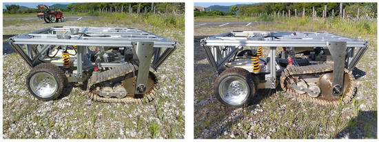
Figure 18.
Vehicle in track mode (left) and wheel mode (right).
4. Discussion
In this paper, we have presented our reconfigurable vehicle, Hadrian. This system can change its contact area by partially lifting the front tracks through a Scott Russel mechanism driven by an electro-hydraulic actuator. We described the mechanical solution adopted and the system architecture, and we finally described in detail the graphical user interface developed for easy remote control of the vehicle. Such a vehicle aims to transport the grape in the vineyard during harvesting while minimizing soil damage and adapting the performance based on the need.
The control interface allows the control of every actuator while monitoring the slip, the rotational velocity, and the torque. The graphical interface represents an important tool for user-friendly vehicle control. Moreover, in the context of the growing development of IoT technologies for agriculture, an interface of this type can be implemented via a smartphone app, not only to facilitate the control of the vehicle during the harvesting period, but also to use the same for field monitoring, collecting data on the state of the soil.
The next step of this research is to test the vehicle in the field and measure the soil damage and performance in several soil conditions. The experimental data will serve as teaching data of a controller, such as a neural network, for making autonomous choices on the best locomotion mode from the vehicle, based on the onboard sensors data and field sensors data. It can be foreseen that the forthcoming improvements to the control system will be able to further improve the behavior of the vehicle developed, making it an important and helpful tool in the field of grape harvesting.
Author Contributions
Conceptualization, E.d.M. and S.K.; methodology, S.K. and E.d.M.; software, S.K.; validation, S.K., E.d.M., N.I.G. and K.I.; formal analysis, S.K. and E.d.M.; investigation, S.K. and E.d.M.; resources, K.I.; data curation, S.K., E.d.M. and N.I.G.; writing—original draft preparation, E.d.M., S.K. and N.I.G.; writing—review and editing, E.d.M. and N.I.G.; visualization, S.K. and E.d.M.; supervision, N.I.G. and K.I.; project administration, E.d.M.; funding acquisition, N.I.G. and K.I. All authors have read and agreed to the published version of the manuscript.
Funding
This research received no external funding.
Data Availability Statement
The data presented in this study are available on request from the corresponding author.
Acknowledgments
We thank our friends Raji Alahmad and Yoshiki Tanaka for their precious support during the realization of the vehicle.
Conflicts of Interest
The authors declare no conflict of interest.
References
- Bechar, A.; Vigneault, C. Agricultural robots for field operations: Concepts and components. Biosyst. Eng. 2016, 149, 94–111. [Google Scholar] [CrossRef]
- Su, L.; Liu, R.; Liu, K.; Li, K.; Liu, L.; Shi, Y. Greenhouse Tomato Picking Robot Chassis. Agriculture 2023, 13, 532. [Google Scholar] [CrossRef]
- Yu, X.; Fan, Z.; Wang, X.; Wan, H.; Wang, P.; Zeng, X. A lab-customized autonomous humanoid apple harvesting robot. Comput. Electr. Eng. 2021, 96, 107459. [Google Scholar] [CrossRef]
- Zhou, C.; Jun, H.; Xu, Z.; Yue, J.; Ye, H.; Yamg, G. A Novel Greenhouse-Based System for the Detection and Plumpness Assessment of Strawberry Using an Improved Deep Learning Technique. Front. Plant Sci. 2020, 11, 559. [Google Scholar] [CrossRef] [PubMed]
- Visconti, P.; de Fazio, R.; Primiceri, P.; Cafagna, D.; Strazzella, S.; Giannoccaro, N.I. A solar-powered fertigation system based on low-cost wireless sensor network remotely controlled by farmer for irrigation cycles and crops growth optimization. Int. J. Electr. Telecom. 2020, 66, 59–68. [Google Scholar]
- Keller, T.; Sandin, M.; Colombi, T.; Horn, R.; Or, D. Historical increase in agricultural machinery weights enhanced soil stress levels and adversely affected soil functioning. Soil Tillage Res. 2019, 194, 104293. [Google Scholar] [CrossRef]
- Eriksson, J.; Hakansson, I.; Danfors, B. The Effect of Soil Compaction on Soil Structure and Crop Yields; Swedish Institute of Agricultural Engineering: Uppsala, Sweden, 1974. [Google Scholar]
- Lal, R. Soil Structure and Sustainability. J. Sustain. Agric. 1991, 1, 67–92. [Google Scholar] [CrossRef]
- Keller, T. Soil Compaction and Soil Tillage-Studies in Agricultural Soil Mechanics. Ph.D. Thesis, Department of Soil Science, Swedish University of Agricultural Science, Uppsala, Sweden, 2004. [Google Scholar]
- Keller, T.; Berli, M.; Ruiz, S.; Lamandè, M.; Arvidsson, J.; Schionning, P.; Selvadurai, A.P.S. Transmission of vertical soil stress under agricultural tyres: Comparing measurements with simulations. Soil Tillage Res. 2019, 140, 106–117. [Google Scholar] [CrossRef]
- ten Damme, L.; Stettler, M.; Pinet, F.; Vervaet, P.; Keller, T.; Munkholm, L.J.; Lamandè, M. The contribution of tyre evolution to the reduction of soil compaction risks. Soil Tillage Res. 2019, 194, 104283. [Google Scholar] [CrossRef]
- Chamen, W.C.; Moxey, A.P.; Towers, W.; Balana, B.; Hallet, P.D. Mitigating arable soil compaction: A review and analysis of available cost and benefit data. Soil Tillage Res. 2015, 146, 10–25. [Google Scholar] [CrossRef]
- White, R.E. Understanding Vineyard Soils; Oxford University Press: Oxford, UK, 2015. [Google Scholar]
- Horn, R. Stress-strain effects in structured unsaturated soils on coupled mechanical and hydraulic processes. Geoderma 2003, 116, 77–88. [Google Scholar] [CrossRef]
- Lamandé, M.; Greve, M.H.; Schjonning, P. Risk assessment of soil compaction in Europe—Rubber tracks or wheels on machinery. Catena 2018, 167, 353–362. [Google Scholar] [CrossRef]
- Visconte, C.; Cavallone, P.; Carbonari, P. Mechanism for the Locomotion Layout Reconfiguration of the Agri_q Mobile Robot. In Advances in Service and Industrial Robotics: Results of RAAD; Springer: Berlin/Heidelberg, Germany, 2020; pp. 390–399. [Google Scholar]
- Gerhart, G.R. The Bekker Model Analysis for Small Robot Vehicles; US Army TACOM: Warren, MI, USA, 2004. [Google Scholar]
- di Maria, E. Running Gear Size Selection of a Wheel/Track Reconfigurable Grape Transporting Vehicle by FEM Analysis. Ph.D. Thesis, Graduate School of Life Science and Systems Engineering, Kyushu Institute of Technology, Kitakyushu, Japan, 2021. [Google Scholar]
- Statista. Available online: www.statista.com (accessed on 20 June 2023).
- Reina, G.; Milella, A.; Galati, R. Terrain assessment for precision agriculture using vehicle dynamic modelling. Biosyst. Eng. 2017, 162, 124–139. [Google Scholar] [CrossRef]
- Reynolds, A.G.; Vanden Heuvel, J.E. Influence of Grapevine Training Systems on Vine Growth and Fruit Composition: A Review. Am. J. Enol. Vitic. 2009, 60, 251–268. [Google Scholar] [CrossRef]
- di Maria, E.; Reina, G.; Ishii, K.; Giannoccaro, N.I. Rolling resistance and sinkage analysis by comparing FEM and experimental data for a grape transporting vehicle. J. Terramechanics 2021, 97, 59–70. [Google Scholar] [CrossRef]
- Grazioso, A.; di Maria, E.; Giannoccaro, N.I.; Ishii, K. Multibody Modeling of a New Wheel/Track Reconfigurable Locomotion System for a Small Farming Vehicle. Machines 2022, 10, 1117. [Google Scholar] [CrossRef]
- Kaufmann, R. Environmental Science; McGraw-Hill: New York, NY, USA, 2008. [Google Scholar]
- Adams, H. Chassis Engineering. Chassis Design, Building & Tuning for High-Performance Cars; HP Books: New York, NY, USA, 1992. [Google Scholar]
- Wong, J.Y. Terramechanics and Off-Road Vehicle Engineering: Terrain Behaviour, Off-Road Vehicle Performance and Design, 2nd ed.; Butterworth-Heinemann: Oxford, UK, 2010. [Google Scholar]
- Visual Basic Documentation. Available online: https://learn.microsoft.com/en-us/dotnet/visual-basic/ (accessed on 20 June 2023).


Disclaimer/Publisher’s Note: The statements, opinions and data contained in all publications are solely those of the individual author(s) and contributor(s) and not of MDPI and/or the editor(s). MDPI and/or the editor(s) disclaim responsibility for any injury to people or property resulting from any ideas, methods, instructions or products referred to in the content. |
© 2023 by the authors. Licensee MDPI, Basel, Switzerland. This article is an open access article distributed under the terms and conditions of the Creative Commons Attribution (CC BY) license (https://creativecommons.org/licenses/by/4.0/).