Article

Topology and Size Optimized Design and Laser Welding of the U-Frame for Free-Space Laser Communication Telescopes

1
Changchun Institute of Optics, Fine Mechanics and Physics, Chinese Academy of Sciences, Changchun 130033, China
2
University of Chinese Academy of Sciences, Beijing 100039, China
3
Chang Guang Satellite Technology Ltd., Changchun 130012, China
*
Author to whom correspondence should be addressed.
Machines 2023, 11(9), 868; https://doi.org/10.3390/machines11090868
Submission received: 19 July 2023 / Revised: 10 August 2023 / Accepted: 16 August 2023 / Published: 29 August 2023
(This article belongs to the Section Machine Design and Theory)

Abstract

:
The success of laser communications heavily relies on the stiffness, dynamic properties, static performance, and manufacturability of the U-frame. The U-frame is a fundamental element in satellite-to-ground laser communication telescopes. However, there is currently a lack of research on the optimal design of U-frames, leading to a significant gap between ideal construction and practical manufacturability. To address these concerns, this study proposes a comprehensive approach that combines multi-objective topology optimization and multi-start size optimization techniques. This approach considers the multidisciplinary constraints imposed by mechanical, control, and optical systems. The objective is to achieve both the conceptual and detailed design of a novel U-frame, while also ensuring thorough consideration of the structure’s manufacturability during the optimization process. The prototype of the optimized U-frame was successfully fabricated using laser welding processes. The tensile test conducted on the prototype supported the idea that laser welding can enhance the micro-grain size of the joint, leading to improved overall mechanical properties. In particular, the joint strength achieved through laser welding was found to be 1.5 times greater than that achieved through TIG (Tungsten Inert Gas) welding. Additionally, the results obtained from the free vibration experiment closely aligned with the simulation, confirming the feasibility of manufacturing the optimized structure. The optimized structure demonstrated an improvement of 7.13% in dynamic performance and 29.61% in static performance compared to the first-generation structure. Additionally, there was a reduction of 29.89% in mass without affecting the remaining performance aspects. The successful fabrication of the prototype validates the feasibility of the proposed welding process and highlights the superiority of the new U-frame.

1. Introduction

The increasing number of satellites and the abundance of data in orbit have led to a growing interest in satellite-to-ground laser communications in recent years [1,2,3,4,5]. Laser communication has the potential to achieve rates of up to 200 GB/s [6,7], which is over ten times faster than conventional electromagnetic wave communication. Additionally, laser communication offers several advantages in terms of safety, electromagnetic interference, frequency licensing, and size reduction [1,8,9]. Therefore, laser communication can effectively address the challenge of transmitting large amounts of data from satellites in orbit. During the satellite-to-ground communication phase, a precise and stable astronomical telescope plays a crucial role in enabling laser communication. It is responsible for receiving and transmitting beacon light, as well as pointing and tracking satellites.
The U-frame is a crucial component of the laser communication telescope [5,10] as it plays a vital role in ensuring the success of laser communication. It needs to have a sufficient natural frequency, high stiffness, precise control over resonant frequency, and the ability to handle optical machine loads effectively. At the same time, it should be lightweight to accommodate future installations on vehicles, aircraft, or satellites. Achieving excellent performance, optimal lightweight design, and ease of manufacturing poses a significant challenge due to the multidisciplinary objectives and constraints involved.
Topology and size optimization are widely recognized as the most popular and effective methods for the conceptual and detailed design phases of a new structure [11,12,13]. Youngsuk Jung et al. [11] introduced a multi-material topology optimization process for the lightweight design of bus roof structures. This process took into account multiple displacement constraints, such as self-weight, resulting in a significant weight reduction of 8%. The utilization of multi-objective topological optimization further enhanced the design process. Jarad Limdde et al. [14] developed a periodic space-frame structure that exhibited 14.4% lower maximum stresses, 12.3% greater bending strength (up), and 93.3% greater bending strength (down) compared to an equivalent beam structure. In a study by Jian Song et al. [15], a cascade optimization method combining topology optimization and shape optimization was proposed. This method was used to design a high-performance twin-mesh turbine disc, which resulted in a weight reduction of 21.35% and an increase in strain energy of 8.5% when compared to a single-mesh disc. To minimize the surface error of the reflective mirror, Qu et al. [16] introduced a multi-objective topology optimization with size optimization method. This method successfully reduced the RMS surface error of the mirror to 3.58 nm. Zhang et al. [17] proposed a topology optimization model for multi-design spaces and multi-load cases. They evaluated the performance of several optimized layouts and ensured that the natural frequency and impact resistance met the required standards. Kim et al. [18] proposed an integrated topology and shape optimization method. Through this method, they were able to create a five-spoke steel wheel that showed significant improvements in prototype tests. These improvements included a 59.7% increase in first-order frequency and a 2.2 dB reduction in tire noise compared to a conventional steel wheel. To optimize the structural design of wind turbine blades and to reduce mass and cost, Zhu et al. [19] proposed a topology and size optimization method, resulting in a 3% mass reduction compared to conventional designs. Similarly, Zeng et al. [20] used topology optimization to achieve a 58% weight reduction in the lightweight design of a rectangular mirror for the Small Space Telescope project. Several other papers have also suggested similar approaches to develop new structures and enhance performance [21,22,23,24]. Therefore, it can be concluded that topology and size optimization play a significant role in design work across various fields.
However, there is currently a dearth of research on the optimization of U-frames for laser communication telescopes. Only a limited number of papers discuss U-frames, and these mostly employ single-objective topology optimization or rely on empirical design [10,24,25]. Therefore, the first challenge is to obtain an optimal structure with more superior performance under complex constraints. On the other hand, U-frames are primarily manufactured through casting or TIG (Tungsten Inert Gas) welding. However, casting poses limitations in achieving optimized lightweight and cost-effectiveness, whereas TIG welding faces challenges in fabricating complex and precise structures due to torch position limitations and high heat output. Therefore, the production of precise U-frame structures presents an additional challenge. These challenges will become more pronounced as U-frames enter batch production, especially with the potential increase in the use of laser communications in commercial and civilian applications in the near future.
To address the aforementioned issues, this paper presents a novel integrated topology and size optimization method for laser-welded U-frames used in laser communication telescopes. This paper aims to demonstrate the manufacturability and superiority of the proposed process and structure. The remaining sections of this paper are organized as follows: Section 2 analyzes the structure and performance of the original U-frame. Section 3 provides detailed information on the topology and size optimization process and describes the conceptual and detailed design of the new U-frame. Section 4 presents the results of the prototype experiments conducted to validate the superiority of the new fabricated U-frame. Finally, Section 5 concludes the paper.

2. Finite Element Analysis of the Original Structure

2.1. Introduction of U-Frame

The original telescope is depicted in Figure 1a and consists of an azimuth axis, U-frame, pitch axis, and optical system. The U-frame structure, made of Q235 and fabricated by TIG welding, is shown in Figure 1b. The plates used in the U-frame are 5 mm thick, based on design experience, resulting in a total weight of 129.4 kg. During satellite tracking, pre-calculated position and velocity commands are sent to the azimuth and pitch axis drivers. The two axes then work together to track the satellite. The optical system receives light for communication, whereas the U-frame carries the weight and transmits the motion, ensuring precise and stable pointing.
According to the main functions of U-frames in the communication process, this paper proposes general requirements for the design of U-frames: (1) Higher stiffness to ensure the accurate transmission of azimuth and pitch motion to the optical axis motion, and stable optical axis pointing. (2) Higher natural frequency to prevent low-frequency vibrations, such as seismic waves and wind loads, and to improve adaptability to various vibration environments, especially in vehicle installation cases. (3) Higher control resonance frequency to improve the servo bandwidth of the control system and reduce tracking errors. (4) Higher degree of lightweight to reduce cost.

2.2. Working Condition Analysis

When the telescope system is tracking and communicating, the optical system can move in a pitch space of approximately 90°, from horizontal to zenith. It is important to note that mechanical and optical system performances are at their lowest when the telescope is in the horizontal position. At this position, three working conditions are simultaneously considered:
(1)
When stationary, the entire system is primarily influenced by gravity in the vertical direction.
(2)
When the telescope is subject to other disturbances or fixed in transit on a vehicle, the other directions are affected by 0.2 times the force of gravity due to the slope of the road.
(3)
When the telescope is tracking, the motor provides a maximum rotation torque of approximately 50 Nm to the entire system.

2.3. Finite Element Analysis of the Original Structure

The finite element model of the azimuth, pitch axis, U-frame, and optical system was established based on the actual structure. The adaptive optical module, transmitting terminal, electronics, and fast mirror module are represented as mass-points, and the thread connection is represented by the RBE2 element. The loading conditions for the entire system include its own gravity and the directional torque from the motor. The finite element model established in this study is illustrated in Figure 2a. Figure 2b displays the static deformation of the system, with the secondary mirror assembly of the optical system experiencing the highest deformation. The U-frame exhibits a maximum deformation of approximately 22 μm. By analyzing the relative deformation of the primary and secondary mirror nodes in the optical system, it was found that the maximum relative deformation angle between the two mirrors is approximately 3.66″. This deformation has implications for both the imaging quality of the optical system and the quality of communication. The maximum stress experienced by the structure is only 6.8 MPa, indicating a high level of safety (Figure 2c). The vibration modes corresponding to the first three natural frequencies of the entire system are illustrated in Figure 2d,e. These frequencies are 21.18 Hz, 22.49 Hz, and 45.45 Hz, respectively. The first-order frequency is particularly significant as it helps prevent resonance and serves as a crucial overall evaluation indicator for the entire system. The third-order vibration mode aligns with the excitation direction of the azimuth motor, which rotates around the azimuth axis. Hence, the third-order frequency impacts the rigidity of the control system, servo bandwidth, and tracking accuracy.
In the new design, 304 stainless steel was used, which has good mechanical and welding properties [26]. The mechanical parameters of 304, as shown in Table 1, are closely aligned with those of Q235. Additionally, 304 exhibits good corrosion resistance in most environments. Therefore, it is more suitable for the future deployment of satellite-to-ground laser communication stations worldwide compared to the original Q235.

3. Topology and Size Optimization

3.1. Topology Optimization

The Solid Isotropic Material with Penalties (SIMP) is a widely used numerical FE-based topology optimization method used in various industrial fields [27]. The SIMP method employs a design variable known as pseudo material density, also referred to as the density method. This method allows for the continuous variation of material density between 0 and 1, where 0 represents a void state and 1 represents a solid state. To achieve the desired density distribution of 0/1 (void/solid), the SIMP method applies a power law penalty to the stiffness–density relationship:
K ρ = ρ p K
where K ( ρ ) is the penalized stiffness matrix of the element, K is the real stiffness matrix of an element,  ρ  is the density, and p is the penalization factor.

3.1.1. Mathematical Model

Topology optimization aims to determine an optimal transmission structure path, prioritizing factors beyond lightweight design in the topology phase. In order to enhance the dynamic characteristics, static performance, and optomechanical index simultaneously, we have developed a multi-objective function. Throughout the optimization process, we observed that the first two order frequencies of the entire system were closely aligned. Therefore, we utilized the sum of the first two order frequencies, rather than solely considering the first-order frequency, as the evaluation index for dynamic characteristics. The mean compliance of the system was used as the evaluation index for its static characteristics, which is the reciprocal of system stiffness. The third-order frequency primarily impacts the rigidity and servo bandwidth of the control system. It can be utilized to assess the influence of the U-frame structure on the control system. The stable load-carrying capacity of the U-frame for the optical machine system can be assessed by considering the maximum relative deformation angle of the primary and secondary mirrors. In this regard, the mathematical model of topology optimization can be described as follows:
Maximize :   ρ f 12 f 1 + f 2 f 1 + f 2 i = 0 + ρ f 3 f 3 ( f 3 ) i = 0 ρ c c ( c ) i = 0 ρ ω ω ( ω ) i = 0
Subject   to :   V 0.3 V 0
where f1, f2, and f3 are the first three natural frequencies, respectively; ρ f 12 ρ f 3 ρ c , and  ρ ω  are the weighting coefficients of each objective, respectively (according to the importance of these objectives, the values were 0.4, 0.1, 0.4, and 0.1, respectively); i represents the number of optimization generations, where i = 0 signifies the initial value before optimization; c is the total flexibility of the whole system, which is the reciprocal of system stiffness;  ω  is the maximum deformation angle between the primary and secondary mirrors, which affects the imaging quality of the optical system and the quality of communication;  V  is the volume of the designed area after optimization; and  V 0  is the incipient volume of the designed area before optimization.

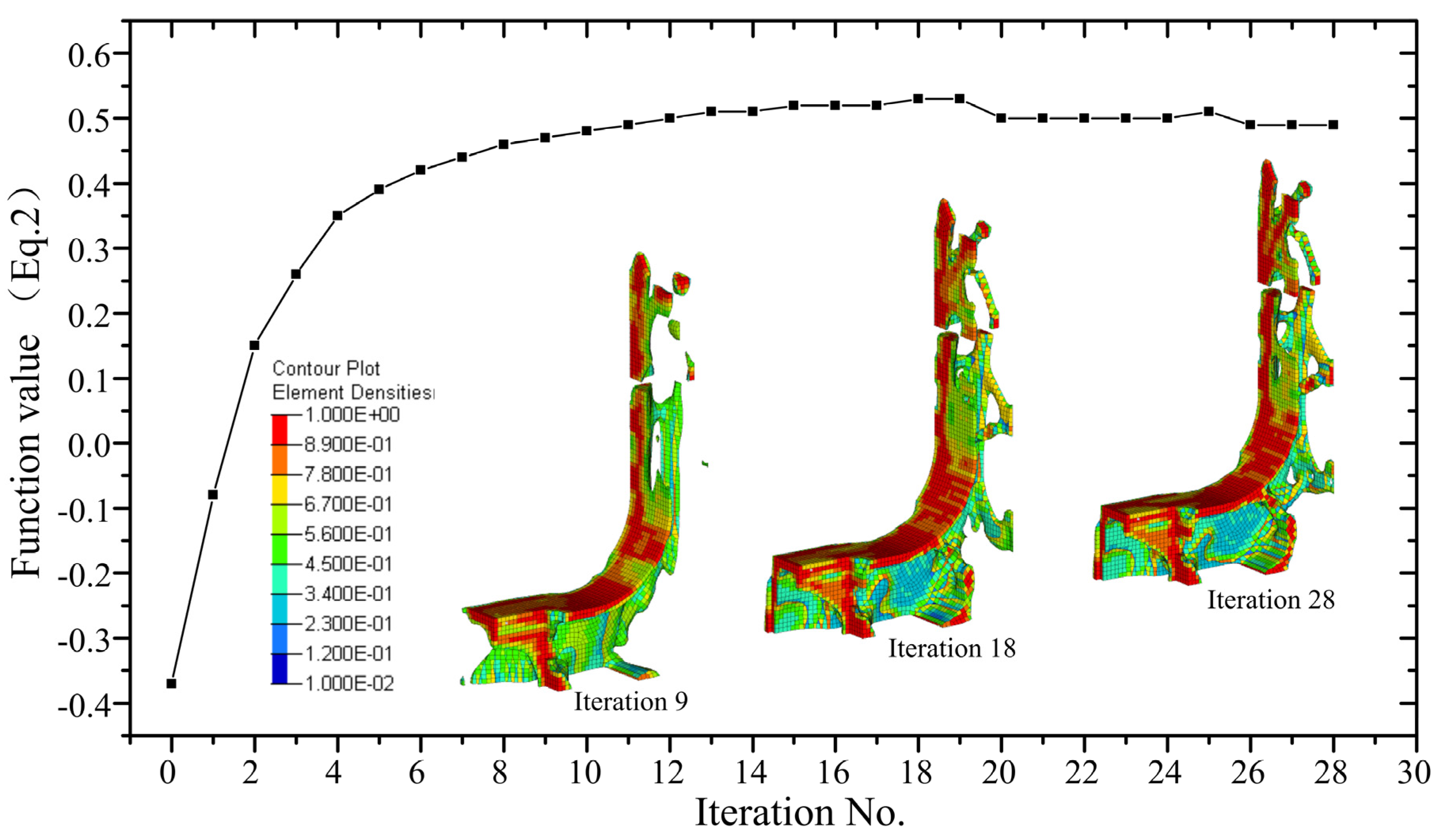
3.1.2. Topology Optimization Process

Unlike the approach taken in the literature [10], this study constructs a finite element model of the entire telescope, with a focus on optimizing the U-frame. This approach allowed us to accurately represent the actual connection scenario when the U-frame is in use, resulting in optimization outcomes that hold more practical significance. As depicted in Figure 3, we applied a fixed constraint of six degrees of freedom to the 12 tapped holes at the bottom. The torque from the azimuthal motor was evenly distributed to the azimuthal axis through the RBE3 element. Additionally, we implemented a symmetrical constraint in two vertical planes to ensure the balance of the support structure. This constraint greatly simplified the operation of the structure, process, and control system. Furthermore, a hollow channel was incorporated for cabling purposes.
The convergence curve of the objective function in topology optimization is presented in Figure 4. It was observed that as the optimization progressed, the force transmission path became more evident and ultimately converged at the 28th iteration. The topology result only displays 1/4 of the structure due to the imposed symmetry constraint.

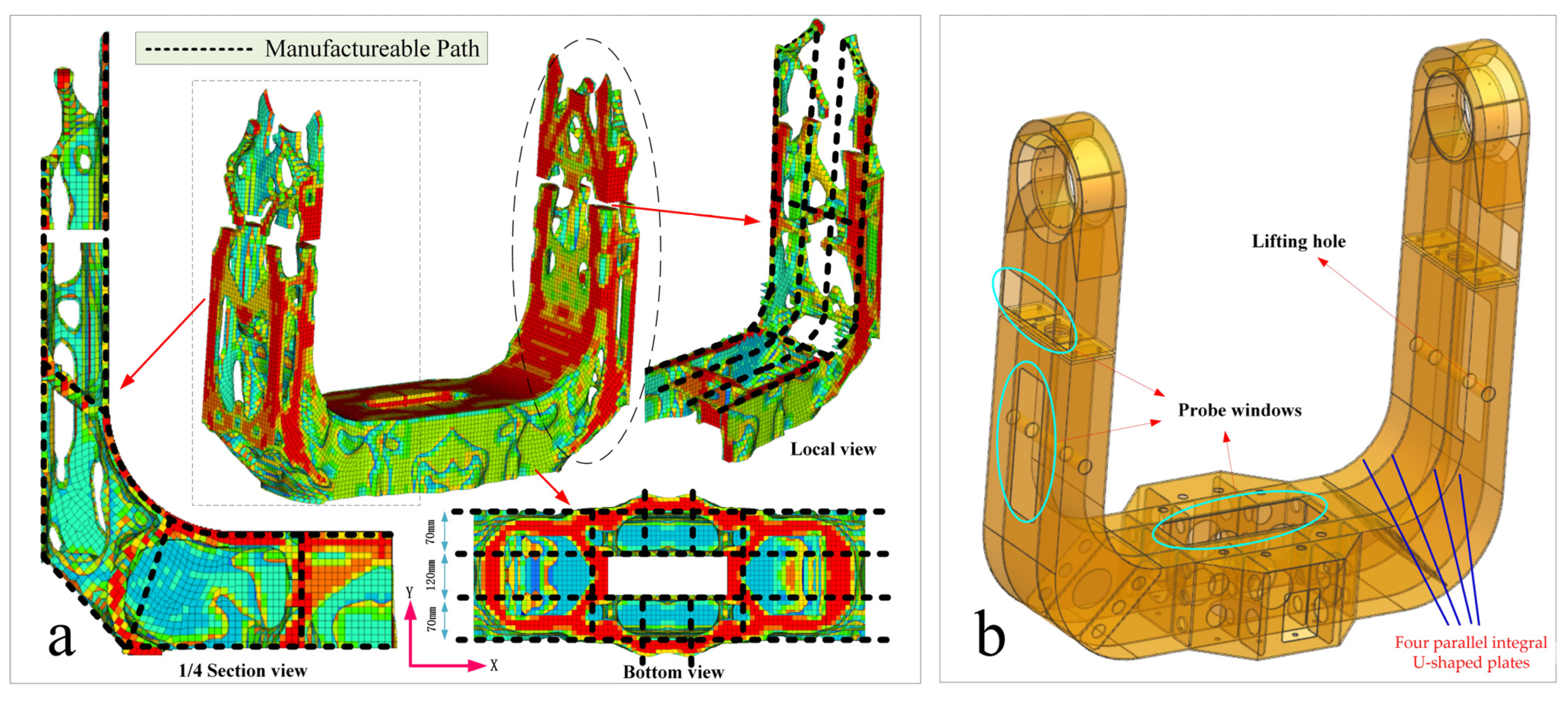
3.1.3. Reconstruction of the Optimized Structure

Figure 5a presents a more detailed topological result, illustrating the force transmission paths in each direction. The diagram reveals that the X-direction comprises four parallel integral U-shaped plates, spaced at distances of 70 mm, 120 mm, and 70 mm, respectively. These plates form the fundamental structure of the U-frame discussed in this paper. The remaining structure is distributed among the four U-shaped plates based on the other topological findings. Figure 5b showcases the reconstructed structure derived from the topology results. The left- and right-side loads were directly connected to the unwelded or uncast cutting U-shaped plates, which possessed high stiffness, thereby ensuring a high level of overall structural integrity. Additionally, the reconstructed structure incorporated lifting and probing windows to facilitate lifting and wiring, provided that the stiffness and strength requirements were met.

3.2. Laser Welding Forming Process

U-frames are typically manufactured through casting or TIG welding. However, for the reconstructed structure depicted in Figure 5b, casting alone does not provide sufficient lightweight properties. On the other hand, implementing TIG welding would be extremely difficult or even impossible due to the complex internal structures and enclosed external structures of the reconstructed topology U-frames. Furthermore, traditional welding methods generate a significant amount of heat, which can result in substantial residual stress and render precision structures unusable. In contrast, laser welding, which is characterized by its non-contact nature, low heat release, high energy density, low thermal distortion, and ease of automation, has become widely adopted in automated batch production, particularly in the automotive industry [28,29]. However, laser welding has not yet been applied in the field of laser communication telescopes. Laser welding has a higher degree of lightweight design compared to casting and a lower heat output compared to TIG welding. Laser welding can also be used to manufacture complex closed structures by concentrating energy to penetrate the outer skin and weld through to the internal structure. Therefore, in this paper, we propose utilizing a laser welding process to manufacture the U-frame.
According to the topology depicted in Figure 5b, this paper proposes two types of 304 welded joints. Figure 6 illustrates these joints: one is the commonly used butt welding process in laser welding, exemplified by piece 1 and piece 2; the other is the penetration welding process, demonstrated by piece 3 and piece 4. The combination of these two joints ensures the overall stiffness, strength, and integrity of the U-frame structure. To establish a constraint for size optimization, preliminary process tests were conducted prior to dimensional optimization. These tests aimed to determine the maximum plate thickness that the laser welding machine could weld under realistic conditions and to determine the minimum power input required to minimize thermal distortion of the structure due to thermal effects. The study examined two types of penetration joints. Figure 6b illustrates that the second type of joint can effectively penetrate a 4 mm external skin at a maximum power of 5.5 kW under actual process conditions. Consequently, the maximum thickness of all outer skins was set at 4 mm. In Figure 6a, it is evident that a 4 mm external skin thickness necessitates a power input of only 4.5 kW to completely weld through the first butt joint. Therefore, in practical scenarios, the power input for both joints was determined to be 4.5 kW and 5.5 kW, respectively.

3.3. Size Optimization

The literature typically relies on the gradient method for size optimization, but this approach has the drawback of being susceptible to local solutions. A practical and straightforward alternative is to optimize from various starting points.

3.3.1. Mathematical Model

Based on the topology optimization and reconstructed structure, we developed a parametric model of the U-frame using shell elements. The shell elements were categorized into 21 types of plates, as depicted in Figure 7. The classification of these plates took into account the two-plane symmetry constraint, as illustrated in Figure 2.
The telescope system was fully modeled, and the overall metrics were utilized as optimization objectives or constraints. In order to ensure successful tracking of the satellite and to maintain communication in our laser communication system, it was necessary for the bandwidth of the servo control to be at least 3 Hz. Additionally, the fundamental frequency of the structure needed to be at least six times the servo bandwidth, which amounted to 18 Hz. However, considering a margin of 50%, the final setting for the fundamental frequency was determined to be 27 Hz. The mathematical model is as follows: The maximum thickness allowed for the skin in the penetration welding process was 4 mm, based on the results of preliminary process tests. On the other hand, the minimum thickness required for the plate used in the threaded joint was 7 mm, whereas all other plates had a thickness ranging from 1.5 to 12 mm for process-related reasons.
Minimize :   V V 0
Subject   to :   f 1 27   Hz
ω 10
1.5   mm T ( 3 , 4 , 5 , 7 , 8 , 9 , 11 , 12 , 15 , 17 , 19 , 21 ) 4   mm
7   mm T ( 1 , 6 , 16 ) 12   mm
1.5   mm T ( 2 , 10 , 13 , 14 , 18 , 20 ) 12   mm
where f1 is the first-order natural frequency; i is the number of optimization generations, where i = 0 signifies the initial value before optimization; w is the maximum relative deformation angle between the primary and secondary mirrors;  V  is the volume of the designed area after optimization;  V 0  is the incipient volume of the designed area before optimization; and T is the thickness of each plate.

3.3.2. Size Optimization Results

Table 2 presents the results obtained from 20 random starting points, out of which 15 different results were obtained. Table 2 only shows these 15 different results. Among these solutions, the 7th starting point yielded the best result, with a mass of 90.72 kg. On the other hand, the worst result was obtained from the 11th search starting point, with an optimized result of 93.66 kg. This represents a difference of 3.24% compared to the optimal solution, highlighting the effectiveness of the multi-start search strategy for size optimization.

4. Experimental Validation

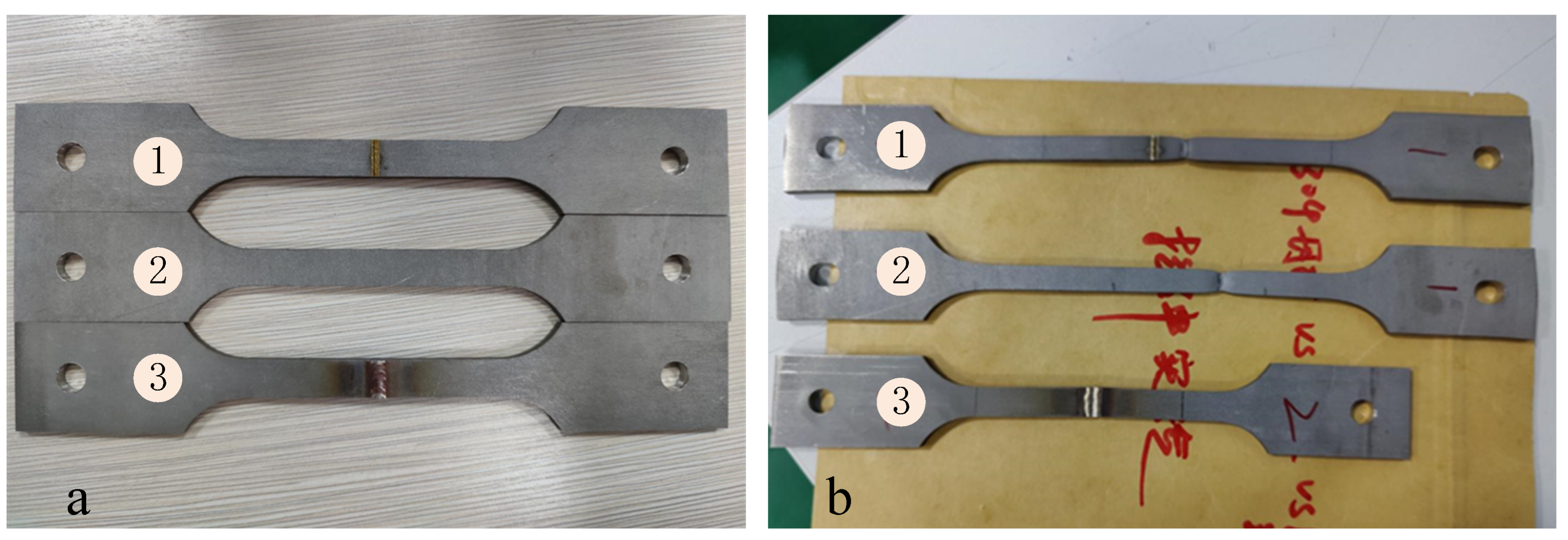
4.1. Tensile Experiment of Laser Welding

The experimental material consisted of 4 mm thick laser-cut 304 plates. Figure 8a shows a group of welded specimens, where No. 1 represents laser-welded specimens, No. 2 represents the pure cut base material, and No. 3 represents argon-arc-welded specimens. The initial length after welding was approximately the same for all three specimens. Subsequently, a 10 T tensile tester was used to fracture the three specimens. The fractured specimens are depicted in Figure 8b. It is evident that the laser-welded specimens fractured from the base material rather than from the joint, indicating that the strength of the laser-welded joint surpasses that of the base material. The specimens welded using the argon arc technique fractured at the joint, suggesting that the strength of the argon-arc-welded joint is lower than that of the base material and also lower than that of laser welding. Furthermore, the temperature of the joint was measured immediately after welding using a temperature measuring gun. It was found that the joint temperature reached up to 250 °C for TIG welding, whereas for laser welding, it was only about 40 °C. This indicates that laser welding releases less heat, leading to the reasonable assumption that its residual thermal stress is also lower.
The test results are presented in Table 3. It can be observed that the laser welding test piece fractured from the parent material, suggesting that the laser welding joint possesses comparable strength to the parent material. Conversely, the strength of the TIG welding test specimen was only 59.6% of the parent material without welding, with a tensile ratio of merely 21.7% of the parent material. These findings indicate that laser welding exhibits superior strength and toughness in comparison to traditional TIG welding.
The metallography of the laser-welded specimen was observed microscopically, as shown in Figure 9. Figure 9a,b displays the high-magnification metallographic structure at the weld and base metal, respectively. The average grain diameter at the weld joint measured approximately 5 μm, which was smaller than the grain size of 11.6 μm at the base metal. This suggests that the laser welding process can effectively enhance different mechanical properties at the joint by reducing the grain size. Such improvement distinguishes laser welding from traditional welding methods. In summary, the laser welding process offers several advantages in terms of tensile strength, toughness, heat dissipation, and the microscopic performance of the joint.

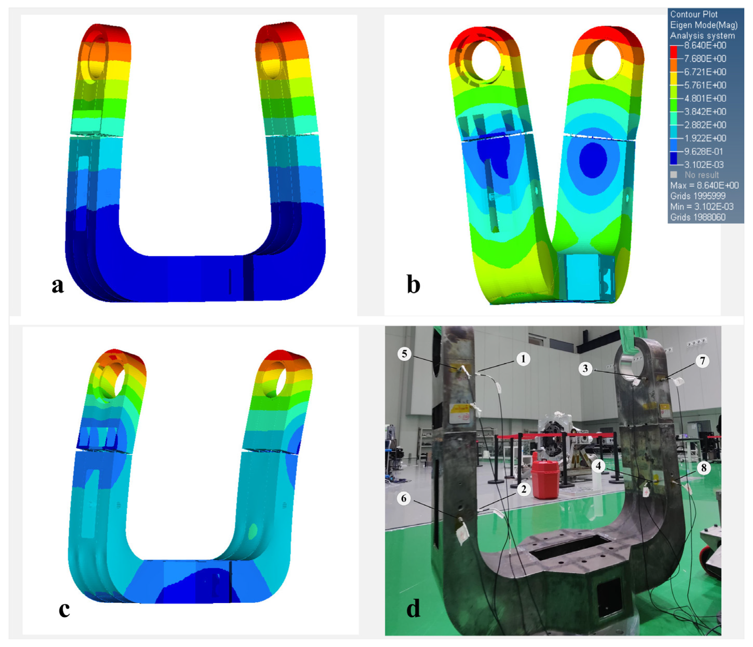
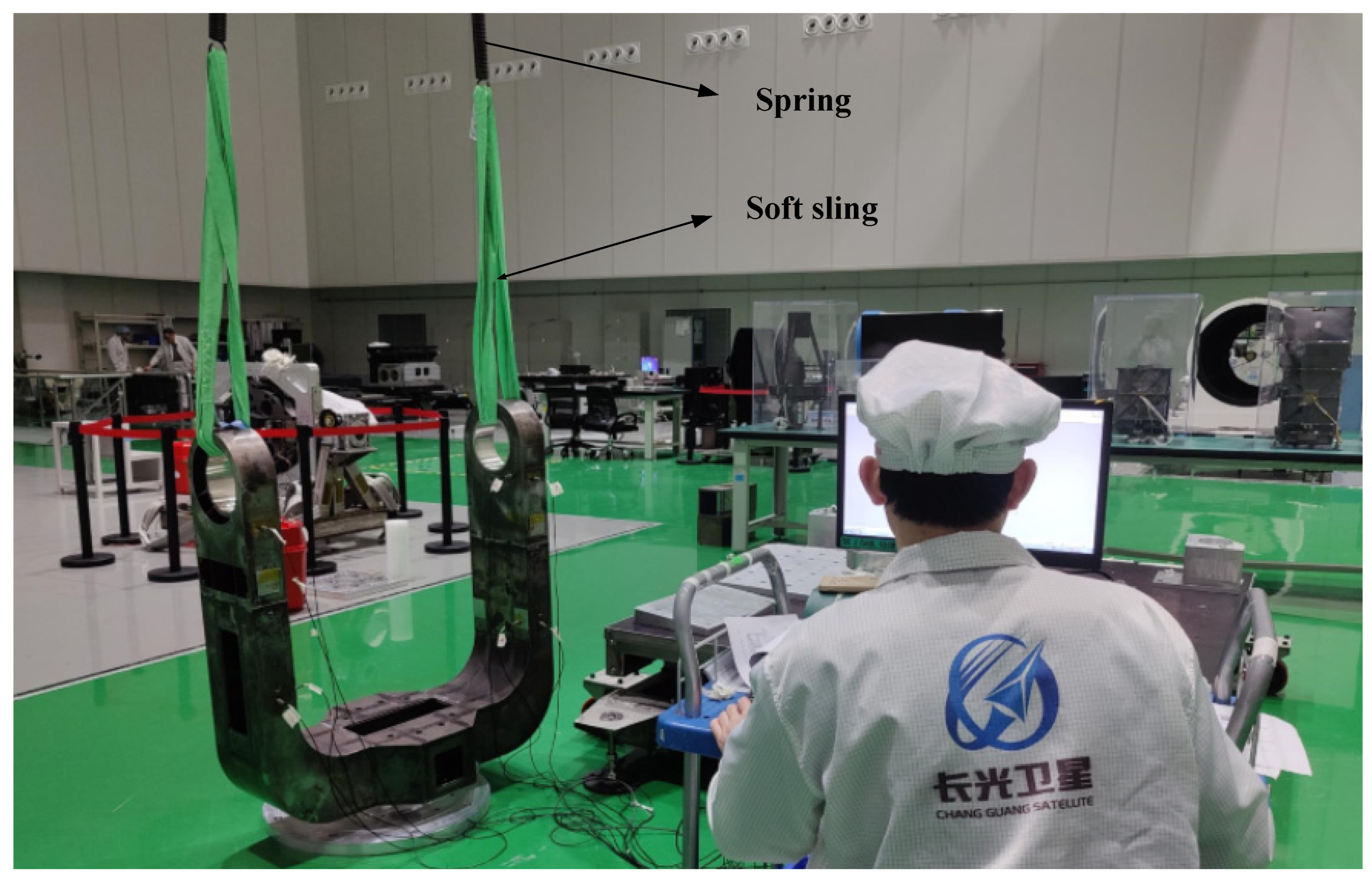
4.2. Free Modal Experiments of the Prototype

To validate the effectiveness of the optimized method and laser welding process, we conducted a free vibration experiment on the prototype. Initially, a free modal finite element analysis was performed, and the results are depicted in Figure 10a–c. These figures illustrate that the first three natural frequencies of the non-rigid body were 77.58 HZ, 126.70 HZ, and 134.63 HZ, respectively. Subsequently, the actual sensor insertion position and power hammer striking position were determined based on the vibration diagram of the first three orders, as shown in Figure 10d.
The experimental setup, as depicted in Figure 11, consisted of a fabricated U-frame prototype suspended by two springs and a soft sling to effectively isolate any ground vibration disturbances.
The vibration mode diagram obtained experimentally for the first three orders is consistent with the simulation results depicted in Figure 10. Additionally, Table 4 displays the frequencies of the first three orders for both the experiments and simulations. The errors for the first three order frequencies are −1.23%, −7.35%, and +1.34%, respectively, resulting in an average error of only −2.53%. These results provide evidence for the success of the fabricated U-frame, as well as the effectiveness of the optimization method and laser welding process proposed in this paper.

5. Conclusions

In the current research on laser communication U-frame optimization, there is a lack of in-depth analysis and the manufacturing process has not yet been fully developed. In this paper, we propose an integrated global topology and multi-start size optimization method to address this gap. We successfully achieved the optimal design and manufacturing of a new U-frame using laser welding. In the topology optimization stage, we considered the constraints of symmetry and cable channels and used the classic SIMP method to obtain the optimal configuration. In the size optimization stage, we considered the manufacturing constraint of laser welding and completed the detailed design. The results are presented in Table 5. Compared to the first-generation structure, the optimized structure showed a 7.13% improvement in dynamic performance, a 29.61% improvement in static performance, and a 29.89% reduction in mass. The remaining performance remained unchanged, which validates the rationality of the proposed optimization method. Additionally, the successful fabrication of the prototype not only demonstrated the feasibility of the proposed welding process but also highlighted the superiority of the new U-frame.

Author Contributions

All authors contributed to the study conception and design. G.L., Z.H., J.Y. and L.T. conducted material preparation, data collection, and the analysis. G.L. wrote the first draft of the manuscript. L.Z. and J.L. planned the entire research work and reviewed and revised the article before submission. All authors have read and agreed to the published version of the manuscript.

Funding

This research was supported by the Jilin Province Science and Technology Development Plan Project (No. 20220201007GX).

Data Availability Statement

Not applicable.

Acknowledgments

The authors would like to thank the editors and anonymous referees for their valuable suggestions and comments.

Conflicts of Interest

The authors declare no conflict of interest.

References

  1. Medina, I.; Hernández-Gómez, J.J.; Torres-San Miguel, C.R.; Santiago, L.; Couder-Castañeda, C. Prototype of a Computer Vision-Based CubeSat Detection System for Laser Communications. Int. J. Aeronaut. Space Sci. 2021, 22, 717–725. [Google Scholar] [CrossRef]
  2. Fischer, E.; Kudielka, K.; Berkefeld, T.; Soltau, D.; Perdigués-Armengol, J.; Sodnik, Z. Adaptive optics upgrades for laser communications to the ESA optical ground station. In Proceedings of the International Conference on Space Optics-ICSO 2020, Online, 30 March–2 April 2021; SPIE: Bellingham, WA, USA, 2021; Volume 118522, pp. 971–980. [Google Scholar] [CrossRef]
  3. McManamon, P.; Vedadi, A.; Willner, A.E.; Choudhary, D.; Montifiore, N.; Harlev, O. High capacity and access rate, data storage using laser communications. Opt. Eng. 2021, 60, 015105. [Google Scholar] [CrossRef]
  4. Israel, D.J.; Edwards, B.L.; Butler, R.L.; Moores, J.D.; Piazzolla, S.; du Toit, N.; Braatz, L. Early results from NASA’s laser communications relay demonstration (LCRD) experiment program. Free.-Space Laser Commun. 2023, 12413, 10–24. [Google Scholar] [CrossRef]
  5. Hu, Z.; Li, S.; Shao, M.; An, Z. Thermal integration analysis of optical machines for space-based laser communications. In Proceedings of the International Conference on Precision Instruments and Optical Engineering, Shanghai, China, 25–27 August 2023; SPIE: Bellingham, WA, USA, 2023; Volume 12585, pp. 7–16. [Google Scholar] [CrossRef]
  6. Wang, J.P.; Bilyeu, B.; Boroson, D.; Caplan, D.; Robinson, B.; Schieler, C.; Haworth, K. High-rate 256+ Gbit/s laser communications for enhanced high-resolution imaging using space-based very long baseline interferometry (VLBI). Free.-Space Laser Commun. 2023, 12413, 54–65. [Google Scholar] [CrossRef]
  7. Schieler, C.M.; Riesing, K.M.; Bilyeu, B.C.; Chang, J.S.; Garg, A.S.; Gilbert, N.J.; Keer, B. On-orbit demonstration of 200-Gbps laser communication downlink from the TBIRD CubeSat. Free.-Space Laser Commun. 2023, 12413, 1241302. [Google Scholar] [CrossRef]
  8. Kim, W.H. BER Analysis of IM and BPPM for Satellite-to-Ground Laser Communications. In Proceedings of the 2020 International Conference on Electronics, Information, and Communication (ICEIC), Barcelona, Spain, 19–22 January 2020; IEEE: New York, NY, USA, 2020. [Google Scholar] [CrossRef]
  9. Toyoshima, M. Recent Trends in Space Laser Communications for Small Satellites and Constellations. J. Light. Technol. 2020, 39, 693–699. [Google Scholar] [CrossRef]
  10. Huang, B.; Li, Z.; Tian, X.; Yang, L.; Han, C.; Chen, B. Concurrent topology and fiber orientation optimization of CFRP structures in space-borne optical remote sensor. Optik 2022, 267, 169652. [Google Scholar] [CrossRef]
  11. Jung, Y.; Lim, S.; Kim, J.; Min, S. Lightweight design of electric bus roof structure using multi-material topology optimisation. Struct. Multidiscip. Optim. 2020, 61, 1273–1285. [Google Scholar] [CrossRef]
  12. Lieu, Q.X. A novel topology framework for simultaneous topology, size and shape optimization of trusses under static, free vibration and transient behavior. Eng. Comput. 2022, 38, 1–25. [Google Scholar] [CrossRef]
  13. Zargham, S.; Ward, T.A.; Ramli, R.; Badruddin, I.A. Topology optimization: A review for structural designs under vibration problems. Struct. Multidiscip. Optim. 2016, 53, 1157–1177. [Google Scholar] [CrossRef]
  14. Lim, J.; You, C.; Dayyani, I. Multi-objective topology optimization and structural analysis of periodic spaceframe structures. Mater. Des. 2020, 190, 108552. [Google Scholar] [CrossRef]
  15. Song, J.; Zhang, Y.; Guo, X.; Gao, H.; Wen, W.; Cui, H. Topology and shape optimization of twin-web turbine disk. Struct. Multidiscip. Optim. 2022, 65, 44. [Google Scholar] [CrossRef]
  16. Qu, Y.; Jiang, Y.; Feng, L.; Li, X.; Liu, B.; Wang, W. Lightweight design of multi-objective topology for a large-aperture space mirror. Appl. Sci. 2018, 8, 2259. [Google Scholar] [CrossRef]
  17. Zhang, Y.; Shan, Y.; Liu, X.; He, T. An integrated multi-objective topology optimization method for automobile wheels made of lightweight materials. Struct. Multidiscip. Optim. 2021, 64, 1585–1605. [Google Scholar] [CrossRef]
  18. Kim, J.; Kim, J.J.; Jang, I.G. Integrated topology and shape optimization of the five-spoke steel wheel to improve the natural frequency. Struct. Multidiscip. Optim. 2022, 65, 78. [Google Scholar] [CrossRef]
  19. Zhu, J.; Cai, X.; Ma, D.; Zhang, J.; Ni, X. Improved structural design of wind turbine blade based on topology and size optimization. Int. J. Low-Carbon Technol. 2022, 17, 69–79. [Google Scholar] [CrossRef]
  20. Zeng, A.; Li, F. Optimal design of rectangular mirror based on topology and size optimization. In Proceedings of the AOPC 2022: Infrared Devices and Infrared Technology; and Terahertz Technology and Applications, Beijing, China, 18–20 December 2022; SPIE: Bellingham, WA, USA, 2023; Volume 12555, pp. 113–118. [Google Scholar] [CrossRef]
  21. Tian, X.; Sun, X.; Liu, G.; Deng, W.; Wang, H.; Li, Z.; Li, D. Optimization design of the jacket support structure for offshore wind turbine using topology optimization method. Ocean Eng. 2022, 243, 110084. [Google Scholar] [CrossRef]
  22. Cui, Y.; Yu, Y.; Yu, J.; Li, Z. Topology-size-material Joint Optimization Design of Long-pan Unsupported Decks. China Mech. Eng. 2022, 33, 2879. [Google Scholar] [CrossRef]
  23. Song, J.; Chen, J.; Wu, Y.; Li, L. Topology Optimization-Driven Design for Offshore Composite Wind Turbine Blades. J. Mar. Sci. Eng. 2022, 10, 1487. [Google Scholar] [CrossRef]
  24. Park, C.H.; Son, Y.S.; Kim, B.I.; Ham, S.Y.; Lee, S.W.; Lim, H.C. Design of tracking mount and controller for mobile satellite laser ranging system. Adv. Space Res. 2012, 49, 177–184. [Google Scholar] [CrossRef]
  25. Hedrick, R.L.; Keller, A.; Haberman, J.; Iott, K.; Hull, T.B.; Clarkson, A.R.; Genet, R. New paradigms for producing high-performing meter class ground-based telescopes. In Modern Technologies in Space-and Ground-based Telescopes and Instrumentation; SPIE: Bellingham, WA, USA, 2010; Volume 7739, pp. 627–641. [Google Scholar] [CrossRef]
  26. Chen, Y.X.; Gao, L. Quality study on laser welding 304 stainless sheet. Metalurgija 2023, 62, 65–67. [Google Scholar]
  27. Rozvany, G.I.N. A critical review of established methods of structural topology optimization. Struct. Multidiscip. Optim. 2009, 37, 217–237. [Google Scholar] [CrossRef]
  28. Sadeghian, A.; Iqbal, N. A review on dissimilar laser welding of steel-copper, steel-aluminum, aluminum-copper, and steel-nickel for electric vehicle battery manufacturing. Opt. Laser Technol. 2022, 146, 107595. [Google Scholar] [CrossRef]
  29. Li, Y.; Xiong, M.; He, Y.; Xiong, J.; Tian, X.; Mativenga, P. Multi-objective optimization of laser welding process parameters: The trade-offs between energy consumption and welding quality. Opt. Laser Technol. 2022, 149, 107861. [Google Scholar] [CrossRef]
Figure 1. (a) Structure of the telescope; (b) structure of the original U-frame.
Machines 11 00868 g001
Figure 2. (a) The finite element model of the original structure; (b) the static deformation of the telescope; (c) the static stress of the telescope; (d) the first vibration mode of the telescope; (e) the second vibration mode of the telescope; and (f) the third vibration mode of the telescope.
Machines 11 00868 g002
Figure 3. Topology optimization finite element model for U-frames.
Machines 11 00868 g003
Figure 4. Convergence curve of the topology optimization.
Machines 11 00868 g004
Figure 5. (a) Detailed results of topology optimization; and (b) reconstruction of the optimized structure.
Machines 11 00868 g005
Figure 6. (a) Weld metallographic diagrams of the first type of 304 joints; and (b) weld metallographic diagrams of the first type of 304 joints.
Machines 11 00868 g006
Figure 7. The parametric model of the U-frame.
Machines 11 00868 g007
Figure 8. (a) Specimens before they fractured; and (b) specimens after they fractured.
Machines 11 00868 g008
Figure 9. (a) The high-magnification metallographic structure at the weld metal; and (b) the high-magnification metallographic structure at the base metal.
Machines 11 00868 g009
Figure 10. (a) The first-order vibration mode; (b) the second-order vibration mode; (c) the third-order vibration mode; and (d) vibration sensor insertion position (The serial number indicates the location of the sensor).
Machines 11 00868 g010
Figure 11. Free modal experiments.
Machines 11 00868 g011
Table 1. The main mechanical parameters of 304 and Q235.
Young Modulus E (GPa)Poisson RatioDensity (kg/m3)Yield Strength (MPa)
3041990.37850≥205
Q2352100.37850≥235
Table 2. Detailed results for size optimization (unit: mm).
R1R2R3R4R5R7R10R11R12R13R14R16R17R18R19
T1777777777777777
T2444444444444444
T3444444444444444
T4444444444444444
T5444434444444443
T6101010101010101010101010101010
T7222222222222222
T8222222222222222
T9222222222222222
T10455444444444444
T11444444444444444
T12222222222222222
T13522336663623353
T14222222222222222
T15222222222222222
T16101010101010101010101010101010
T17222222222222222
T18222222222222223
T19222222222222222
T20333333333333333
T21222222222222222
Weight (kg)92.6892.6393.0092.3392.6890.7292.5393.6692.0792.5392.6392.8191.1491.1191.10
Table 3. Results of the tensile experiment.
Without WeldingBy Laser WeldingBy TIG Welding
Tensile strength (MPa)795773474
Yield strength (MPa)359293256
Tensile elongation at fracture (%)68.56915
Table 4. Experiment and simulation results of the free modal experiment.
Modal No.Simulation Results (Hz)Experiment Results (Hz)Error
177.5876.58−1.29%
2126.70117.39−7.35%
3134.63136.43+1.34%
Mean113.00110.13−2.53%
Table 5. Performance comparison before and after optimization (by simulation).
Original DesignOptimized DesignPercent Change
Dynamic performance (the sum of the first three order frequencies)89.12 Hz95.47 Hz+7.13%
Static performance (flexibility)31.1021.89−29.61%
Optomechanical performance (relative deformation angle)3.66″3.67″+0.27%
Weight129.4 kg90.72 kg−29.89%
Disclaimer/Publisher’s Note: The statements, opinions and data contained in all publications are solely those of the individual author(s) and contributor(s) and not of MDPI and/or the editor(s). MDPI and/or the editor(s) disclaim responsibility for any injury to people or property resulting from any ideas, methods, instructions or products referred to in the content.

