Communication

Mass Flow Function Correlation for Solid and Honeycomb Land Labyrinth Seals including Fin Front Angle, Clearance, Fin Number and Honeycomb Geometry

School of Aerospace and Mechanical Engineering, Korea Aerospace University, 76, Hanggongdaehak-ro, Deogyang-gu, Goyang-si 10540, Gyeonggi-do, Republic of Korea
*
Author to whom correspondence should be addressed.
Machines 2023, 11(9), 880; https://doi.org/10.3390/machines11090880
Submission received: 21 July 2023 / Revised: 29 August 2023 / Accepted: 30 August 2023 / Published: 1 September 2023
(This article belongs to the Section Turbomachinery)

Abstract

:
In this study, the effects of several geometry factors (fin front angle, clearance, number of fins, and honeycomb cell diameter and depth) on the mass flow function of solid and honeycomb land were studied experimentally. The fin front angle considered in the experiment ranged from 60 to 90 degrees, the number of fins was varied between two and three, and the diameter and depth of the honeycomb cell ranged from 1.33 to 4.00 times and 8.08 to 13.08 times the thickness of the fin tip, respectively. The experimental results showed that the mass flow function decreased as the number of fins increased for the solid land labyrinth seal, and the mass flow function increased as the clearance increased. A fin front angle of 60 degrees was found to have the minimum mass flow function. For the honeycomb land labyrinth seal, the mass flow function decreased as the number of fins increased, and the effect of the cell depth was shown to be insignificant compared to the effect of the cell diameter. The effects of cell diameter and cell depth on the mass flow function depended on the conditions of other variables. In addition, the correlation equations of the mass flow functions of the solid land and honeycomb land labyrinth seals are presented based on the experimental results, which represent the effects of the fin front angle, clearance, pressure ratio, and diameter and depth of the honeycomb cell. The correlation equation for the solid land labyrinth seal had an r 2 value of 0.9822, while the correlation equation for honeycomb land had an r 2 value of 0.9621.

1. Introduction

The existence of clearances between blade tips and the casing is inevitable for gas turbines. The leakage flows that occur in these clearances contribute to a large part of the overall turbine efficiency loss [1]. To reduce losses due to tip leakage, various sealing techniques, such as the optimization of the blade cross-sectional shape, brush seal, and labyrinth seal [2,3], are applied to the blade tip. Labyrinth-sealing techniques have been studied since the 20th century. The primary advantages of labyrinth seals are their simple structure and high thermal resistance [4], which lead to them still being applied in modern gas turbines [5,6,7].
A common principle of labyrinth seals at gas turbine blades is to reduce leakages by increasing the flow resistance with fins installed above the blade tip at the clearance. The sealing performance of a labyrinth seal is strongly influenced by associated variables, including the angle, thickness, and number of fins, and the clearance between the casing and fin tips [8,9,10,11,12].
Labyrinth seals are classified into two types, namely solid land labyrinth seals and honeycomb land labyrinth seals, depending on whether a honeycomb structure is applied to the land part. A casing with a honeycomb labyrinth seal has the advantage of being lighter in weight than a casing with a solid land, which can reduce turbine vibration [13], and it has the advantage of being less abrasive than a solid land labyrinth seal when the fin and the casing are in contact due to thermal expansion [14]. For honeycomb land labyrinth seals, it is known that the geometric factors of the honeycomb cells (diameter, depth, thickness, etc.) greatly affect the airtight performance of the seal [15,16,17].
Previous research works on labyrinth sealing techniques have mainly reported the effects of geometric factors. Desando et al. [18] experimentally studied the effect of fin thickness on the performance of a solid land labyrinth seal, showing that the leakage flow rate decreases with increasing fin thickness. Kuwamura et al. [19] studied the effect of the position of the fin and the shape of the cavity on the sealing performance in a stepped labyrinth seal, and found that the position of the fin has a significant effect on the sealing performance, and that circular-shaped cavities have a high sealing performance in all pressure ranges. Lee et al. [20] experimentally investigated the effects of factors such as the fin front angle (FFA), number of fins, and clearance on the sealing performance of a solid land labyrinth seal and presented experimental correlations for each variable. In addition, flow visualization using the Schlieren technique was used to observe the flow separation at the fin tip and the vortex structure inside the cavity. Li et al. [21] compared the effects of the cell depth and cell diameter in honeycomb labyrinth seals through computational analysis and found that an optimal cell depth and diameter exist under each condition. Using experimental and computational results, Zhang et al. [22] proposed a correlation equation involving the thickness of the fin tip and the number of fins, FFA, clearance, and pressure ratio in a stepped labyrinth seal, and proposed a correction factor based on the FFA. Chun and Ahn [23] conducted a computational study to investigate the effect of the geometric parameters of a stepped labyrinth seal on the discharge coefficient. Their research underscored that among these parameters, the step height within the stepped labyrinth seal exhibited the highest degree of sensitivity in relation to the discharge coefficient. Hu et al. [24] carried out a computational analysis to examine the effect of the geometry of honeycomb cells on the flow characteristics in a honeycomb labyrinth seal. They observed that, in honeycomb lands with relatively large diameters, an increase in the honeycomb cell depth led to a noticeable increase in the mass flow rate.
In this study, we conducted experimental research to investigate the impact of various geometric factors on the actual performance of a labyrinth seal. The factors examined in this research include the number of fins, fin frontal angle, clearance, and honeycomb cell depth and diameter. Tests were performed in a test rig with a straight flow path, and both solid and honeycomb lands were considered. Based on the experimental results, the mass flow function correlation equations for each geometric factor are presented in the paper.

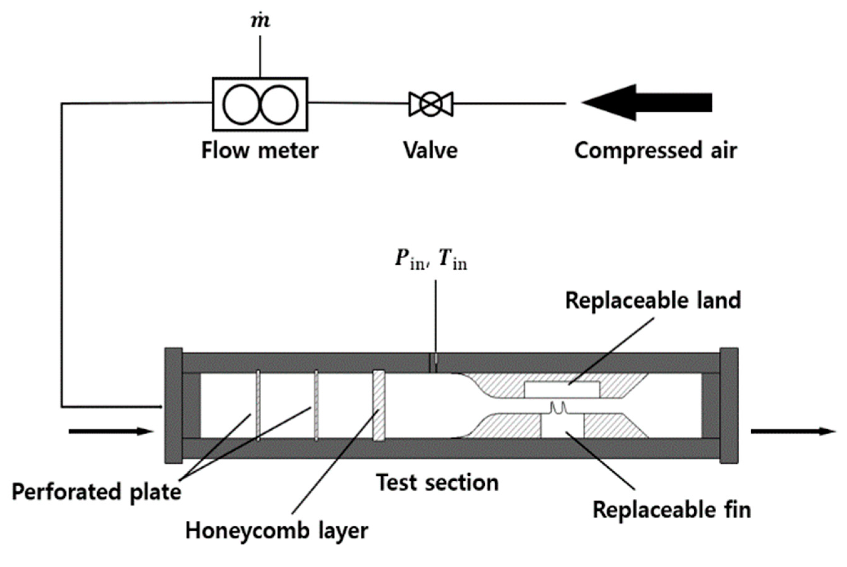
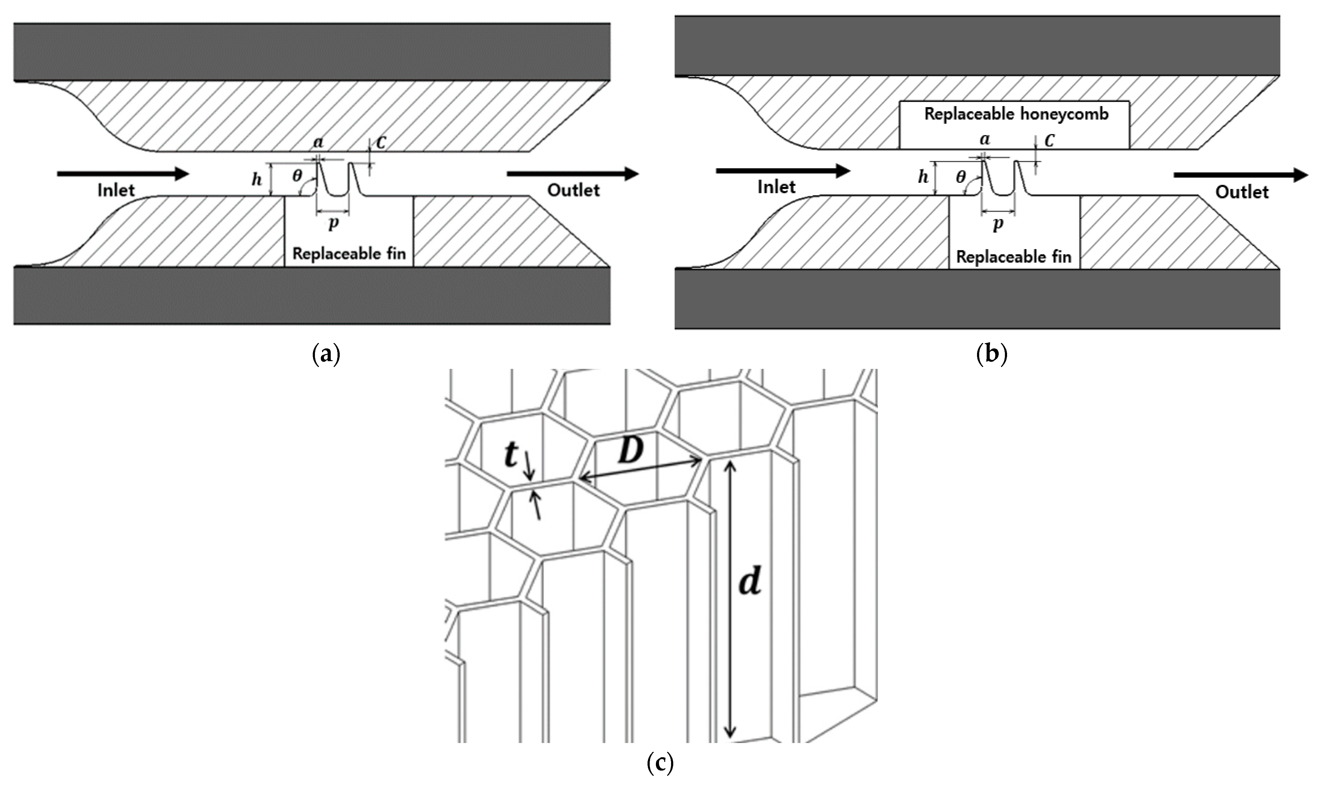
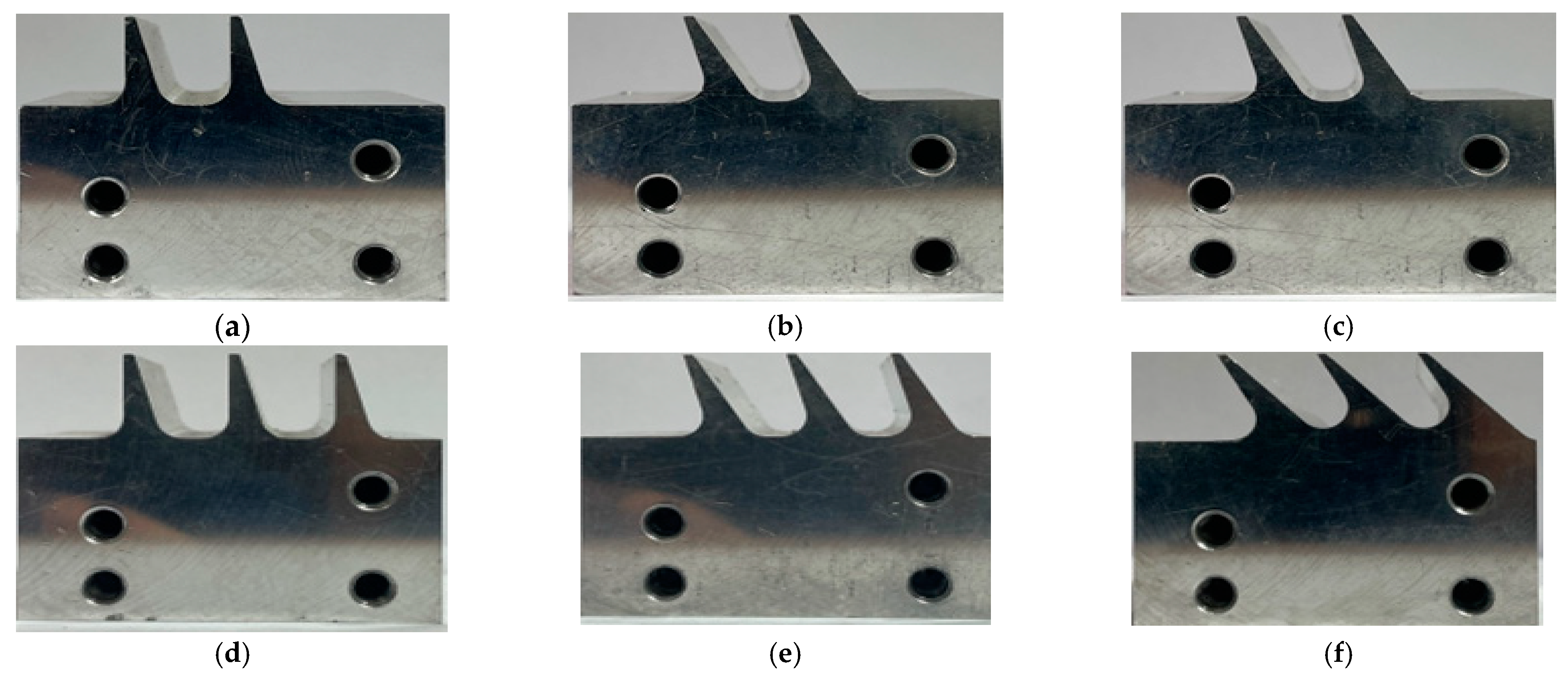
2. Experimental Methods

The experimental setup of this study is shown in the schematic diagram of Figure 1. Compressed air at 8.6 bar enters the test section after passing through a valve and a flow meter. The width of the test section was 40 mm, and the outlet was exposed to the atmosphere. The flow was controlled by adjusting the inlet and outlet pressure ratio. The inlet pressure of the flow was measured using a manometer (PX409-050GL, OMEGA, USA), and the mass flow rate corresponding to each pressure ratio was measured using a thermal mass flow meter (FD-TMS-50 mm, Republic of Korea). To ensure a uniform inlet flow, a perforated plate and a honeycomb layer were installed in the main flow path before the test section.
Figure 2a,b shows the geometry of the test piece and the shape factors of the labyrinth seal, where a is the thickness of the fin, C is the clearance between the land and the fin tip, h is the height of the fin, p is the distance between the fin, and θ is the FFA. Figure 2c shows the parameters of the honeycomb cell used in the honeycomb labyrinth seal. D is the diameter of the honeycomb cell, d is the depth of the honeycomb cell, and t is the thickness of the honeycomb cell. Figure 3 shows the replaceable fins used in the experiments, which were conducted using varying FFA and N. Table 1 shows the range of each geometric factor used in this study.
ϕ = m ˙ T 0 A c P 0
The performance of the seal with each geometric factor was analyzed using the mass flow function [25], which is defined by Equation (1). In Equation (1), m ,   ˙ T 0 ,   A c , P 0 are the mass flow rate, total temperature, clearance area, and total pressure, respectively. The clearance area was calculated by physically measuring the size of the clearance during the installation. The predicted measurement uncertainty of the mass flow function was estimated to be 2.3% [26].

3. Results and Discussions

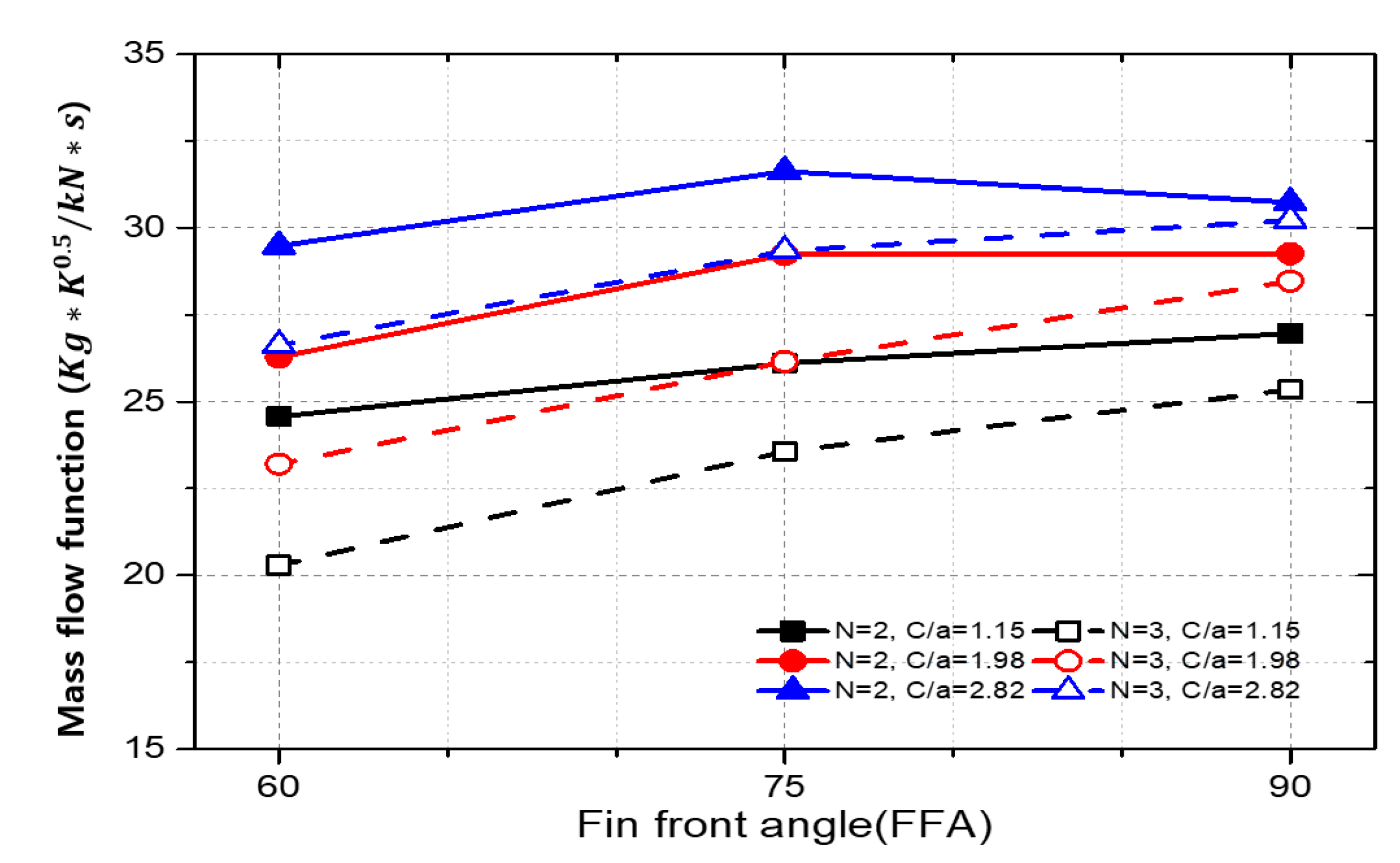
3.1. Solid Land Labyrinth Seal

Figure 4 shows the measured mass flow function as a function of the pressure ratio, clearance, and the number of fins for each FFA. For all three angles, the mass flow function decreases as the number of fins increases from two to three, which confirms the same trend as Zhang et al. [22]. In addition, the mass flow function increases as the pressure ratio increases, and the mass flow function increases as the clearance increases in all cases. The trend observed in the tests was similar to previous studies [15,16,22].
Figure 5 shows the effect of FFA on the size of the clearance and the number of fins at a pressure ratio of 1.7. Smaller FFAs resulted in lower mass flow functions in all cases. This effect was greater when the number of fins was three.
Based on the measured data and Zhang’s correlation equation [22], a new correlation equation of the mass flow function, Equation (2), with the FFA, clearance, pressure ratio, and number of fins as variables, was derived. Table 2 shows the range of geometric factors reflected in the correlation equation and the coefficient of determination. The coefficient of determination, r 2 , was 0.9822, showing a good fit.
ϕ = ( i θ + j ) C a k 1 0.9 N 1 N l 1 P R 2 N m

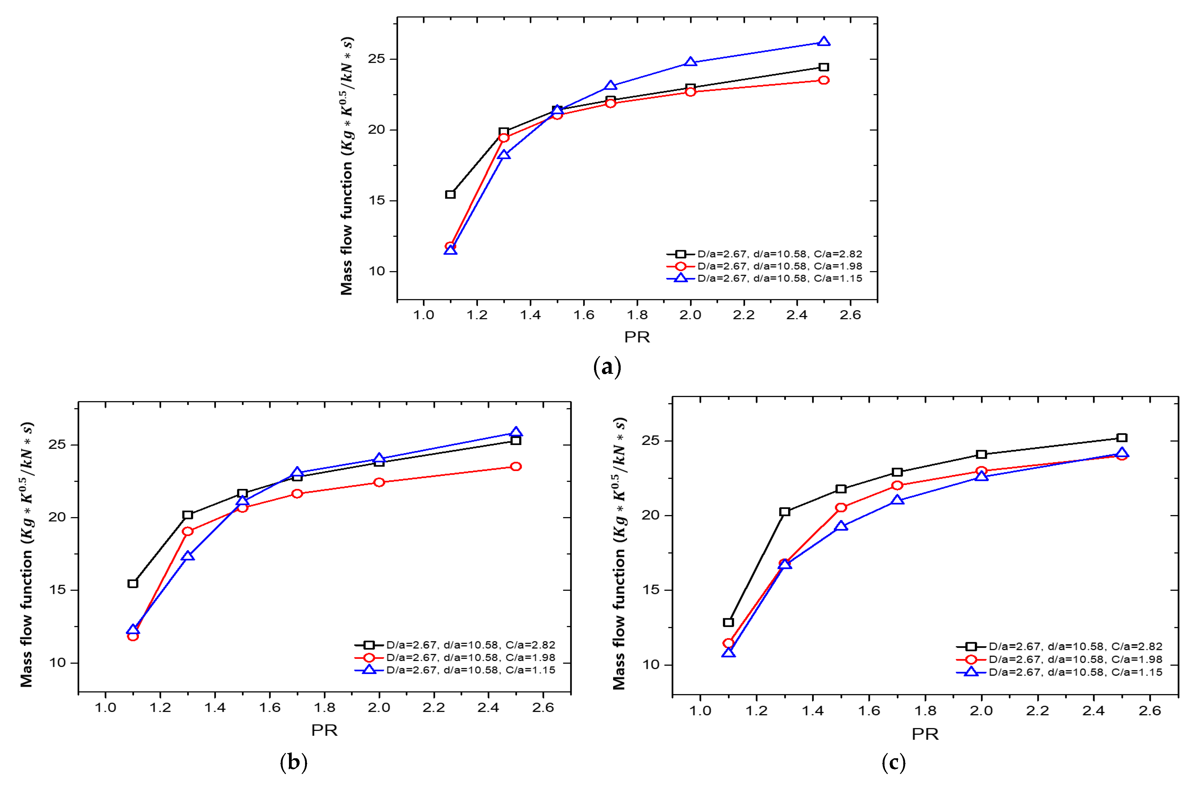
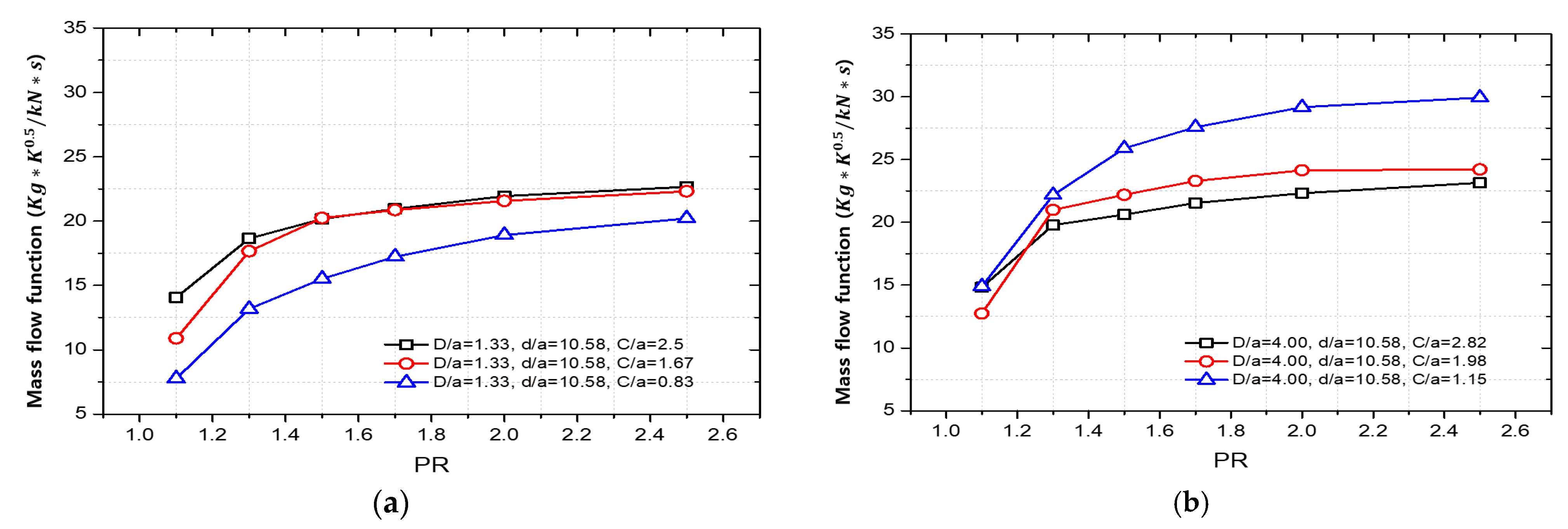
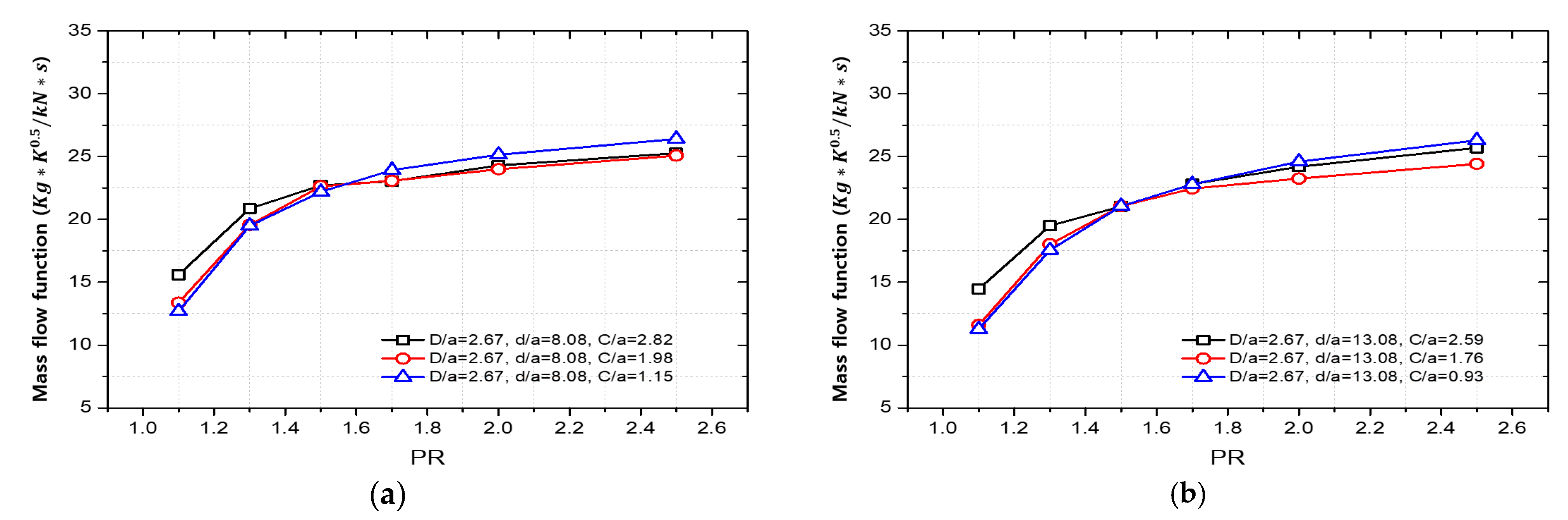
3.2. Honeycomb Land Labyrinth Seal

Figure 6 compares the effect of the number of fins for the honeycomb land application at FFA = 90°. As the pressure ratio increases, the mass flow function tends to increase. The mass flow function tends to decrease when the number of fins increases from two to three, as in the case of the solid land.
Figure 7 shows the effect of clearance per FFA in a honeycomb labyrinth seal with the same honeycomb cell size (D/a = 2.67, d/a = 10.58). Below the pressure ratio of 1.5, all FFAs showed higher mass flow functions with larger clearances, but this trend was not observed above the pressure ratio of 1.5, except for the case of FFA = 60°. In other words, for the honeycomb land labyrinth seal, the effect of clearances on the mass flow function depends on the FFA and pressure ratio. Kaczyński et al. [15] found that the flow pattern of a labyrinth seal changes with the clearance and FFA. According to that, our results in Figure 7 can be understood as the changed effect of the clearance due to the changed flow pattern.
Figure 8 shows a comparison of the effects of cell diameters and clearances for a given cell depth. The mass flow function increased with the increasing clearance for D/a = 1.33 (Figure 8a), but the opposite trend was observed for D/a = 4.00 (Figure 8b). The trend in Figure 8b shows the same trend as in the study of Frączek et al. [16], whereas Figure 8a shows the same trend as the experimental results of the solid land labyrinth seal. This is interpreted as the tendency of the leakage flow to behave in a similar way as the solid land, as it decreases to enter the cell as the cell diameter decreases. On the other hand, the leakage flow entering the cell increases as the cell diameter increases, and the changed flow pattern increases the effective clearance, causing the mass flow function to increase. In other words, the effect of the clearance on the mass flow function depends on the cell diameter.
Figure 9 compares the effects of cell depth and clearance for a given cell diameter, and Figure 9a,b shows the mass flow function graphs for d/a = 8.08 and 10.58, respectively. In both cases, the mass flow function increased with increasing clearance under a PR below 1.5. However, the mass flow function showed the maximum at the smallest clearance under a PR above 1.5. Therefore, the effect of cell diameter on the mass flow function showed dependence on the pressure ratio and clearance. The effect of clearance was not significant for a given cell depth. This is because the effect of cell diameter is stronger than that of cell depth, as explained by Desando et al. [18].
Based on the measured results and Zhang’s correlation equation [22], we derived a new correlation equation with FFA, clearance, honeycomb cell depth, and diameter as variables. The honeycomb shape factors, cell diameter and depth, were added as variables, and the correlation equation is shown in Equation (3). Table 3 shows the range of shape factors reflected in the correlation equation and the coefficient of the correlation equation. The coefficient of the determinant for the correlation equation, r 2 , was 0.9621, which is lower than that of solid land. This is because the influence of the diameter and depth of the honeycomb cell tended to vary depending on the clearance, as described earlier.
ϕ = i θ + j C a k D d l 1 0.9 N 1 N m 1 P R 2 N n

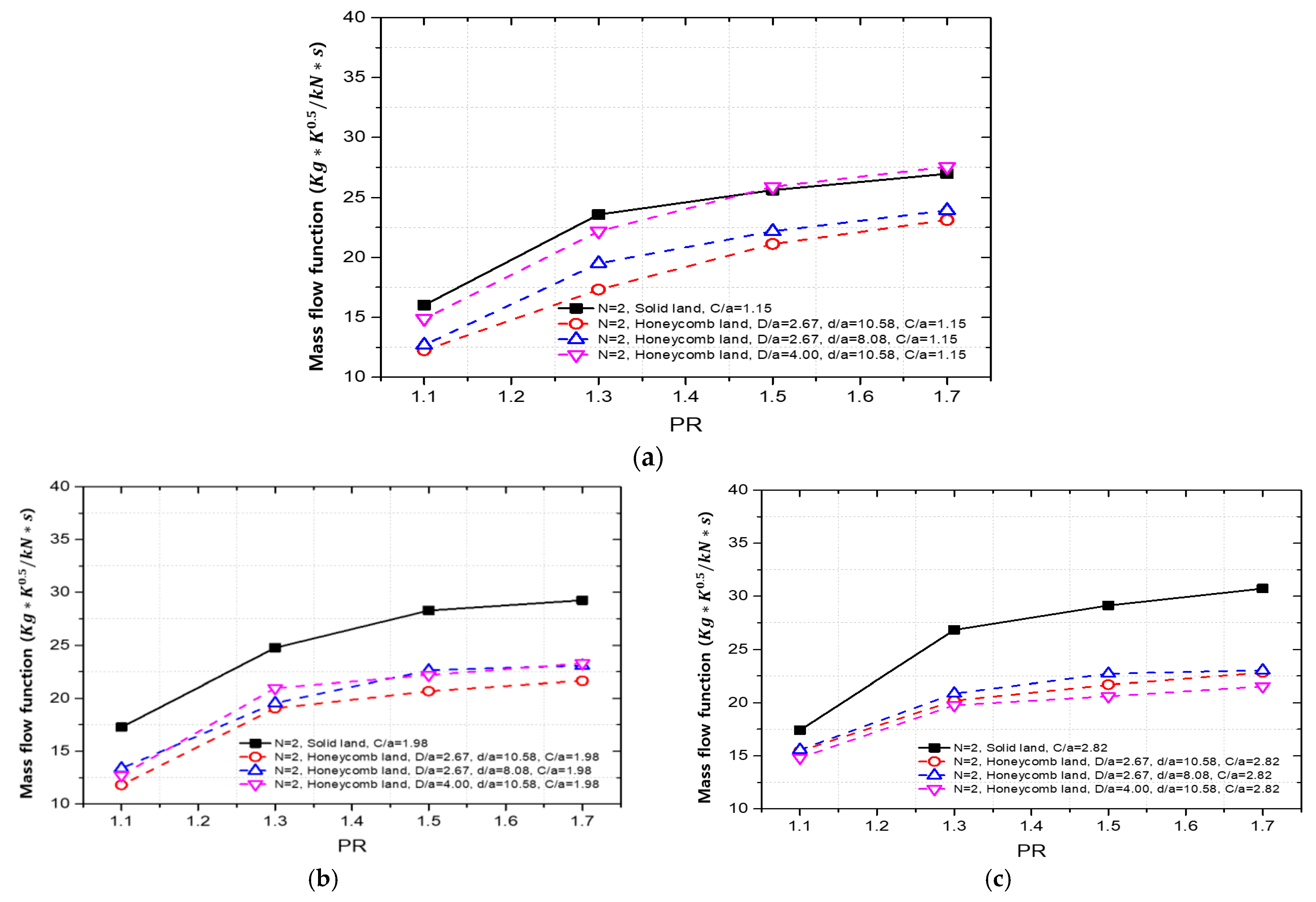
3.3. Comparison of Solid Land and Honeycomb Land Labyrinth Seal

Figure 10 is a graph comparing the solid land labyrinth seal and the honeycomb land labyrinth seal with the same number of fins, clearance, and FFA. In most cases, the honeycomb land application showed lower mass flow function values, indicating that the honeycomb land application improved the sealing performance.

4. Conclusions

In this study, the effects of various geometric factors on the sealing performance of solid land labyrinth seals and honeycomb land labyrinth seals were experimentally verified. The experimental results were used to derive a correlation equation of the mass flow function with the relevant geometric factors. The main results are as follows.
(1)
Regarding the solid land labyrinth seal, the mass flow function exhibited its lowest value at the FFA (forward facing angle) of 60°. Additionally, the mass flow function demonstrated a decreasing trend as the clearance decreased.
(2)
In both solid and honeycomb lands, employing three fins resulted in a higher sealing performance compared to using two fins.
(3)
The effect of the honeycomb cell diameter on the flow rate function varied depending on the clearance, while the effect of cell depth on the flow rate function was relatively minor compared to the influence of cell diameter.
(4)
In general, the honeycomb land labyrinth seal exhibited lower mass flow function values compared to the solid land seal with the same number of fins, FFA, and clearance.
(5)
Based on the experimental results, correlation equations were derived for both solid and honeycomb lands. It is expected that these equations can be applied to various seal designs.
In this study, experiments were conducted in a simplified test rig to establish flow rate function correlations for honeycomb land and solid land labyrinth seals. In the future, it is suggested that similar studies are carried out in experimental setups that simulate the real operational conditions of gas turbines, such as under rotational conditions or using annular-shaped devices.

Author Contributions

Conceptualization, H.J.K. and J.S.K.; methodology, H.J.K. and Y.J.K.; software, H.J.K. and Y.J.K.; validation, H.J.K. and W.K.; formal analysis, H.J.K.; investigation, H.J.K. and Y.R.J.; resources, J.S.K.; data curation, H.J.K. and Y.J.K.; writing—original draft preparation, H.J.K.; writing—review and editing, H.J.K., S.P. and J.S.K.; supervision, J.S.K.; project administration, J.S.K.; funding acquisition, J.S.K. All authors have read and agreed to the published version of the manuscript.

Funding

This research was supported by Basic Science Research Program through the National Research Foundation of Korea (NRF), funded by the Ministry of Education (grant number: 2022R1A6A1A03056784) and The National Research Foundation of Korea (NRF) grant, funded by the Korea government (MSIT) (2021M3F6A1085955).

Data Availability Statement

Data sharing is not applicable to this article.

Conflicts of Interest

The authors declare no conflict of interest.

Nomenclature

A c Clearance area
a Fin tip thickness
C Clearance
D Honeycomb cell diameter
d Honeycomb cell depth
FFAFin front angle
h Fin height
m Mass flow rate
N Number of fins
P 0 Total pressure
p Pitch of fin
PRPressure ratio
T 0 Total temperature
t Honeycomb cell thickness
θ Fin front angle (degree)
Φ Mass flow function ( k g K 0.5 / k N s )

References

  1. Denton, J.D. The 1993 IGTI Scholar Lecture: Loss Mechanisms in Turbomachines. ASME J. Turbomach. 1993, 115, 621–656. [Google Scholar] [CrossRef]
  2. Chupp, R.E.; Hendricks, R.C.; Lattime, S.B.; Steinetz, B.M. Sealing in Turbomachinery, NASA Technical Report, NASA/TM-2006-214341; NASA: Cleveland, OH, USA, 2006. [Google Scholar] [CrossRef]
  3. Wadia, A.R.; Booth, T.C. Rotor-Tip Leakage: Part II—Design Optimization Through Viscous Analysis and Experiment. J. Eng. Power 1982, 104, 162–169. [Google Scholar] [CrossRef]
  4. Steinetz, B.M.; Hendricks, R.C.; Braun, M.J. Turbomachine Sealing and Secondary Flows, Part 1—Review of Sealing Performance, Customer, Engine Designer, and Research Issues, NASA Technical Report, NASA/TM-2004-211991/Part1; NASA: Cleveland, OH, USA, 2004. [Google Scholar]
  5. Stocker, H.L. Determining and improving labyrinth seal performance in current and advanced high performance gas turbines. AGARD Seal Technol. Gas Turbine Eng. 1978, 237, 13.1–13.22. [Google Scholar]
  6. Zimmermann, H.; Wolff, K.H. Air System Correlations: Part 1—Labyrinth seals. In ASME International Gas Turbine and Aeroengine Congress and Exhibition, stockholm, sweden, Volume 4: Heat Transfer; Electric Power; American Society of Mechanical Engineers: Atlanta, GA, USA, 1998; V004T09A048. [Google Scholar]
  7. Vermes, G. A fluid mechanics approach to the labyrinth seal leakage problem. ASME J. Eng. Power 1960, 83, 161–169. [Google Scholar] [CrossRef]
  8. Kim, T.S.; Kang, Y.; Moon, H.K. Aerodynamic Performance of Double-Sided Labyrinth Seal, Fluid Machinery and Fluid Me-Chanics: 4th International Symposium; Springer: Berlin/Heidelberg, Germany, 2009; pp. 377–382. [Google Scholar]
  9. Micio, M.; Facchini, B.; Innocenti, L.; Simonetti, F. Experimental Investigation on Leakage Loss and Heat Transfer in a Straight through labyrinth seal. In Proceedings of the ASME Turbo Expo: Turbine Technical Conference and Exposition, Vancouver, LM, Canada, 6–10 June 2011; Volume 54655, pp. 967–979. [Google Scholar] [CrossRef]
  10. Michaud, M.; Vakili, A.; Meganathan, A.; Zielke, R.; Shuster, L.; Terrell, J. An experimental study of labyrinth seal flow. In Proceedings of the International Joint Power Generation Conference collocated with Turbo Expo 2003, Atlanta, GA, USA, 16–19 June 2003; Volume 36924, pp. 497–504. [Google Scholar]
  11. Vakili, A.D.; Meganathan, A.J.; Michaud, M.; Radhakrishnan, S. An experimental and numerical study of labyrinth seal flow. In ASME Turbo Expo 2005: Power for Land, Sea, and Air Volume 3: Turbo Expo 2005, Parts A and B; ASME: New York, NY, USA, 2005; pp. 1121–1128. [Google Scholar]
  12. Kang, Y.; Kim, T.S.; Kang, S.Y.; Moon, H.K. Aerodynamic performance of stepped labyrinth seals for gas turbine applications. In ASME Turbo Expo 2005: Power for Land, Sea, and Air Volume 4: Heat Transfer, Parts A and B; ASME: New York, NY, USA, 2010; pp. 1191–1199. [Google Scholar]
  13. Li, J.; Yan, X.; Li, G.; Feng, Z. Effects of pressure ratio and sealing clearance on leakage flow characteristics in the rotating honeycomb labyrinth seal. In ASME Turbo Expo: Power for Land, Sea, and Air, Montreal, Canada Volume 4: Turbo Expo 2007, Parts A and B; ASME: New York, NY, USA, 2007; pp. 1199–1206. [Google Scholar] [CrossRef]
  14. Bunker, R.S. Axial Turbine Blade Tips: Function, Design, and Durability. J. Propuls. Power 2006, 22, 271–285. [Google Scholar] [CrossRef]
  15. Kaczyński, P.; Szwaba, R.; Wasilczuk, F.; Flaszyński, P.; Doerffer, P. Leakage flow reduction in different configuration of labyrinth seal on a turbine blade tip. J. Phys. Conf. Ser. 2018, 1101, 012012. [Google Scholar] [CrossRef]
  16. Frączek, D.; Bochon, K.; Wróblewski, W. Influence of Honeycomb Land Geometry on Seal Performance. In Proceedings of the ASME Turbo Expo 2016: Turbomachinery Technical Conference and Exposition, Seoul, South Korea, 13–17 June 2016; Volume 5A: Heat Transfer. [Google Scholar]
  17. Yan, X.; Chen, X.; He, K. Influence of Shroud Seal Dimensions on Aerodynamic Performance of Steam Turbine Stages: Part I—Honeycomb Seal. In Proceedings of the ASME Turbo Expo 2016: Turbomachinery Technical Conference and Exposition, Seoul, South Korea, 13–17 June 2016; Volume 8: Microturbines, Turbochargers and Small Turbomachines, Steam Turbines. [Google Scholar]
  18. Desando, A.; Rapisarda, A.; Campagnoli, E.; Taurino, R. Numerical Analysis of Honeycomb Labyrinth Seals: Cell Geometry and Fin Tip Thickness Impact on the Discharge Coefficient. In Proceedings of the ASME Turbo Expo 2015: Turbine Technical Conference and Exposition, Montreal, QC, Canada, 15–19 June 2015; Volume 5C: Heat Transfer. [Google Scholar]
  19. Kuwamura, Y.; Matsumoto, K.; Uehara, H.; Ooyama, H.; Tanaka, Y.; Nishimoto, S. Development of New High-Performance Labyrinth seal Using Aerodynamic Approach. In Proceedings of the ASME Turbo Expo: Turbine Technical Conference and Exposition, San Antonio, TX, USA, 3–7 June 2013; Volume 5B: Oil and Gas Applications, Stream Turbines. [Google Scholar]
  20. Lee, S.I.; Kang, Y.J.; Kim, W.J.; Kwak, J.S. Effects of tip clearance, number of teeth, and tooth front angle on the sealing performance of straight and stepped labyrinth seals. J. Mech. Sci. Technol. 2021, 35, 1539–1547. [Google Scholar] [CrossRef]
  21. Li, J.; Kong, S.; Yan, X.; Obi, S.; Feng, Z. Numerical Investigations on Leakage Performance of the Rotating Labyrinth Honeycomb Seal. ASME J. Eng. Gas Turbines Power 2010, 132, 062501. [Google Scholar] [CrossRef]
  22. Zhang, L.; Zhu, H.; Liu, C.; Tong, F. Experimental and Numerical Investigation on Leakage Characteristic of Stepped Labyrinth Seal. In Proceedings of the ASME Turbo Expo 2016: Turbomachinery Technical Conference and Exposition, Seoul, South Korea, 13–17 June 2016; Volume 5A: Heat Transfer. [Google Scholar]
  23. Chun, Y.H.; Ahn, J. Optimizing the Geometric Parameters of a Stepped Labyrinth Seal to Minimize the Discharge Coefficient. Processes 2022, 10, 2019. [Google Scholar] [CrossRef]
  24. Hu, B.; Yao, J.; An, N.; Mi, H.; Bai, X. Numerical investigation on the effects of HC geometry on the flow and heat transfer in the disk cavity system at the turbine vane root. Appl. Therm. Eng. 2023, 230, 120794. [Google Scholar] [CrossRef]
  25. Kim, T.-S.; Kang, S.-Y. Investigation of Leakage Characteristics of Straight and Stepped Labyrinth Seals. Int. J. Fluid Mach. Syst. 2010, 3, 253–259. [Google Scholar] [CrossRef]
  26. Kline, S.J. The Purposes of Uncertainty Analysis. ASME J. Fluids Eng. 1985, 107, 153–160. [Google Scholar] [CrossRef]
Figure 1. Schematic of the test rig.
Machines 11 00880 g001
Figure 2. Parameters of labyrinth seal. (a) Solid land labyrinth seal (b) Honeycomb land labyrinth seal (c) Parameters of honeycomb cell.
Machines 11 00880 g002
Figure 3. Replaceable pieces with fins (FFA = 90°, 75°, 60°, n = 2, 3). (a) N = 2, FFA = 90° (b) N = 2, FFA = 75° (c) N = 2, FFA = 60° (d) N = 3, FFA = 90° (e) N = 3, FFA = 75° (f) N = 3, FFA = 60°.
Machines 11 00880 g003
Figure 4. Effect of number of fin and clearance. (a) FFA = 90°, (b) FFA = 75°, (c) FFA = 60°.
Machines 11 00880 g004
Figure 5. Effect of FFA (PR = 1.7).
Machines 11 00880 g005
Figure 6. Effect of number of fins (FFA = 90°).
Machines 11 00880 g006
Figure 7. Effect of clearance per FFA in honeycomb land labyrinth seal (N = 2, D/a = 2.67, d/a = 10.58) (a) FFA = 90°, N = 2 (b) FFA = 75°, N = 2 (c) FFA = 60°, N = 2.
Machines 11 00880 g007
Figure 8. Effect of cell diameter (a) D/a = 1.33, d/a = 10.58 (b) D/a = 4.00, d/a = 10.58.
Machines 11 00880 g008
Figure 9. Effect of cell depth (FFA = 90°, N = 2) (a) D/a = 2.67, d/a = 8.08 (b) D/a = 2.67, d/a = 13.08.
Machines 11 00880 g009
Figure 10. Effect of honeycomb land (FFA = 90°) (a) C/a = 1.15, (b) C/a = 1.98, (c) C/a = 2.82.
Machines 11 00880 g010
Table 1. Geometry of labyrinth seal.
Seal TypeSolid LandHoneycomb Land
FFA (θ)60°, 75°, 90°
Number of fin (N)2, 3
Fin tip thickness (a)1.2 mm
Pitch (p/a)10
Clearance (C/a)1.16~2.821.15~3.65
Honeycomb cell thickness (t/a)-0.25
Honeycomb cell diameter (D/a)-1.33~4.00
Honeycomb cell depth (d/a)-8.08~13.08
Table 2. Coefficient of correlation of solid land labyrinth seal.
ParametersConstraints
FFA (θ)90~60°
Clearance (C/a)1.1~2.82
Number of fin (N)2, 3
PR1.1~1.7
r 2 0.9822
i0.1915
j22.5635
k0.2250
l−0.2230
m0.4594
Table 3. Coefficient of correlation of honeycomb land labyrinth seal.
ParametersConstraints
FFA (θ)90~60°
Clearance (C/a)0.83~1.98
Number of fin (N)2, 3
Cell diameter (D/a)1.33~2.67
Cell depth (d/a)8.08~13.08
PR1.1~1.7
r 2 0.9621
i0.1019
j34.1676
k0.0465
l0.1790
m−0.2072
n0.4824
Disclaimer/Publisher’s Note: The statements, opinions and data contained in all publications are solely those of the individual author(s) and contributor(s) and not of MDPI and/or the editor(s). MDPI and/or the editor(s) disclaim responsibility for any injury to people or property resulting from any ideas, methods, instructions or products referred to in the content.

