Abstract
In order to solve the problem of poor stability of hard brittle material in cutting process, a 45° groove micro-textured composite bionic tool was proposed. Under the same cutting parameters and conditions, the temperature rise and cutting force can be suppressed, and the tool stability can be reduced. Firstly, the design tool was modeled in three dimensions and the optimal bionic tool structure was optimized by finite element simulation technology. Secondly, four microstructures were constructed on the basis of biomimetic tools, and the optimum microstructures were selected based on shear force, stress distribution and chip discharge capacity. The smallest microstructure size parameters were obtained by changing the spacing of microstructures. Finally, on the basis of optimizing the micro-textured biomimetic tool, the surface of the tool was coated, and the influence of coating material on tool performance was discussed. The results showed that the cutting fracture rate of the material increased and the cutting accumulation phenomenon was alleviated obviously when the 45° chute micro-textured bionic tool with composite coating was used for machining. The cutting stability of the tool was enhanced and chip adhesion was reduced when cutting forces and cutting temperatures were reduced. At the same time, compared with conventional tools, the main cutting force and radial force decreased by 35% and 62%, and the cutting temperature decreased by 3.5%. With the decrease in cutting force and cutting temperature, the stability of cutting was enhanced and the phenomenon of chip adhesion on the tool surface was reduced.
1. Introduction
Metal cutting is widely used in the fields of automobile, ship and airplane, and is a pillar industry in the development of the country [1,2]. With the popularization of nanotechnology, higher requirements are put forward for precision, tool processing and working process of mechanical parts [3]. Carbide cutting tools are widely used in cutting because of their good red heat resistance, abrasion resistance and high temperature oxidation resistance [4,5]. However, in the cutting process, when the tool collides with the workpiece, elastic and plastic deformation will occur, causing strong friction between the contact surfaces, causing the tool to be in a high temperature and pressure for a long time, and easy to cause damage to the tool [6,7].
In order to reduce tool wear and prolong tool service life, a large amount of coolant is usually added in the cutting process to avoid excessive wear and tear and cause tool damage. On the one hand, the coolant plays the role of cooling and lubrication, reducing the cutting temperature of the tool; the coolant, on the other hand, can take the remaining chips from the processing area and avoid abrasion. However, a high amount of cutting heat is generated during the cutting process. At high temperatures, the coolant evaporates, gases are discharged into the air, causing air pollution, and the coolant recovery treatment increases production costs [8,9,10]. In order to respond to the development trend of national green manufacturing technology, dry cutting has become the focus of current research [11]. Dry cutting completely eliminates the harm caused by cutting fluid, but it creates a lot of debris during material removal process. Because of its thermoplasticity, it is not easy to break, can easily cause chip accumulation and cannot guarantee stability of processing and product quality [12]. Therefore, in view of the above problems, domestic and foreign scholars found through tribology and bionics that micro-textured machining on the tool surface can reduce friction and chip adhesion [13,14]. Arulkirubakaran et al. studied the effect of micro-textured tools on titanium alloy cutting and found that micro-textures on the surface in front of the tool can reduce the contact area and friction between the tool and the cutting block [15]. Patel, K et al. studied the influence of micro-textured parameters on the force, stress and wear during cutting titanium alloy, and found that micro-textured width, depth and edge distance had a great influence on the cutting force. Micro-textured depth and distance from the main blade have an important effect on cutting temperature [16]. Chen, Y et al. studied the influence of micro-textured ball-end milling cutters on the surface quality of workpieces after milling, and found that a reasonable arrangement of micro-textured on the tool surface could improve the surface quality of machined parts and effectively reduce the generation of burrs [17]. Li, Q et al. found that appropriate micro-textured morphology can significantly reduce tool wear, improve workpiece surface quality and reduce tool surface stress [18]. In summary, based on bionics and friction, the combination of microfabrication and cutting tools can improve the cutting performance of the tool and, compared with the traditional tool, has more advantages, including: it can reduce the tool–chip contact mask, it can increase the surface heat dissipation area of the tool, it has microfabrication parts to capture the cutting of the micro debris to avoid abrasive wear. As the demand for tools becomes more diversified, researchers have found that biological teeth and scales have excellent wear reduction and anti-wear effects; so, the gradual imitation of tool morphology has become a current research focus [19,20]. Lian Yunsong et al. designed bionic cutting tools according to the surface structure of subarca granosa, and found that the optimized bionic cutting tools played a certain role in improving cutting force, cutting temperature and other aspects compared with ordinary cutting tools [21,22]. In order to further improve the cutting performance of the tool, the concept of coating tool is proposed [23,24]. Coating tool is a tool-surface-coating treatment, coating material and tool matrix combined to form a protective film and improve tool durability [25]. In the traditional processing of the rake face of the tool and the workpiece material in close contact, it is difficult for the cutting fluid to enter the close contact area, and the extensive use of cutting fluid is likely to cause environmental pollution and rising processing costs. The proposal of self-lubrication of micro-textured tools provides a theoretical basis for solving this problem. Mohanty, A. et al. [26] investigated the effect of coating materials on high speed milling of strong steels and found that the tools exhibited good machining performance when milling with multi-coated tools, which promoted efficient and high-quality machining. Zheng, G. et al. [27] investigated the friction wear mechanism of coated tools under dry-cutting conditions and found that oxide film formed on the surface of the cutter body can prevent the direct contact of the friction vice and plays a positive role in lubrication. Additionally, the combination of surface microstructures and coating materials using microstructures to store the oil film formed under high temperature and high pressure, continuous and stable lubrication conditions for the tool contact area, so that the tool in the dry hard cutting conditions can still be sustained and stable processing.
After the above study, it was found that the surface micro-textured tool shows good performance in optimizing the cutting performance of the tool, and the type and arrangement of micro-textured has some limitations for the optimization of the tool. Therefore, this paper proposed a bionic structure of the tool, which was different from the traditional structure, and combined the surface micro-textured with the coating technology to further optimize the cutting performance of the tool. In this study, the finite element analysis software was used to analyze and compare the effect of four bionic tool structures on cutting force to select the optimal bionic tool structure. On this basis, four kinds of different morphology micro-textures were constructed and the density of the micro-textures was changed, and the optimal bionic micro-textured tool was selected through the test with the cutting force, stress distribution, and the ability to promote chip removal was taken as the measurement criteria. Finally, the surface treatment of the bionic micro-textured tool was carried out to investigate the effect of composite coating materials on the cutting performance.
2. Finite Element Simulation Analysis
AISI 52100 bearing steel is widely used in the machinery industry due to its good thermal processing performance, but it is a difficult material with high hardenability and complicated processing steps [28]. Compared with cutting tools made of other materials, the carbide tool has higher production efficiency, but in the hard cutting state, it is easy for phenomena such as edge collapse and thermal deformation to occur [29,30]. The bionic carbide tool cutting the bearing steel was simulated by the finite element simulation software, and the bionic carbide tool was comprehensively evaluated with the cutting force as the evaluation standard, and the optimal structure of the bionic carbide tool was optimized.
2.1. Finite Element Simulation and Bionic Tool
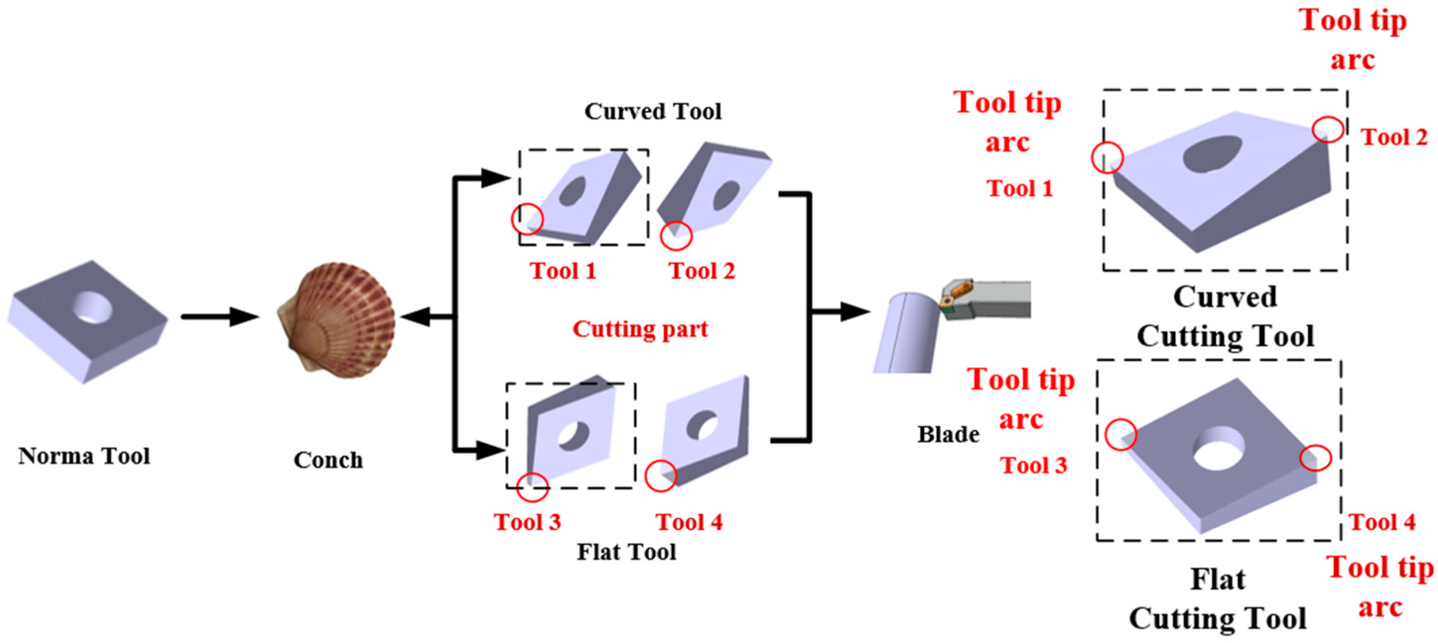
In different fields, the cutting material and machining accuracy are very different. Therefore, when cutting material is not the same as the ability of cutting tool surface to adhere to the chip, cutting performance will change. According to the high requirement of modern machining, the biological structure of nature shows great potential in improving the performance of engineering field, and so, this paper constructed a kind of blade which is different from traditional tool shape. Firstly, by observing the biological world, it is known that shells have good mechanical properties because of the interaction between the hard material and microstructure, and the way, size and shape of the perlite structure on the surface affect the bearing capacity of shells. Therefore, based on the good mechanical properties of shells and combined with traditional tools, four bionic tools were designed as shown in Figure 1 below. In order to compare and analyze the performance of different kinds of tool, the tool was modelled as shown in Figure 1. Tool 1 is a convex curved tool with a certain angle protruding from the tip of the blade to the inside of the blade. Tool 2 is a concave curved surface bionic tool which is dented at a certain angle from the tip of the knife to the inside of the blade. Tool 3 is a convex planar biomimetic tool with a certain angle protruding from the tip of the tool. The Tool 4 starts at the tip of the knife and goes down at an angle to the inside of the tool to flatten out the front of the bionic tool. Therefore, based on the good mechanical properties of shells and combined with traditional tools, four bionic tools were designed as shown in Figure 1 below. In order to compare and analyze the performance of different kinds of tool, the tool was modelled as shown in Figure 1.

Figure 1.
Bionic carbide tool. Tool 1 is a convex curved tool with a certain angle protruding from the tip of the blade to the inside of the blade. Tool 2 is a concave curved surface bionic tool which is dented at a certain angle from the tip of the knife to the inside of the blade. Tool 3 is a convex planar biomimetic tool with a certain angle protruding from the tip of the tool. Tool 4 starts at the tip of the knife and goes down at an angle to the inside of the tool to flatten out the front of the bionic tool. A three-dimensional model of a conventional tool was also established as a comparison test.
The designed bionic tool was imported into the AdvantEdge finite element simulation software, the mesh division of the tool and the workpiece, in order to ensure the simulation of precision and accuracy of the tool, the maximum mesh size was set to 1 mm, the minimum mesh size was set to 0.1 mm, away from the cutting region of the workpiece’s maximum mesh size was set to 3 mm and the cutting region of the minimum mesh size was set to 0.1 mm. The workpiece material was defined as AISI 52100, the size of the workpiece was 30 mm round bar greater than five times the tool feed, the tool material was defined as a carbide tool, the initial temperature of the workpiece and the tool was 20 °C, the cutting path was set for the tool to turn the workpiece outside the circle of a week and the finite element simulation mesh model of the tool workpiece is shown in Figure 2.
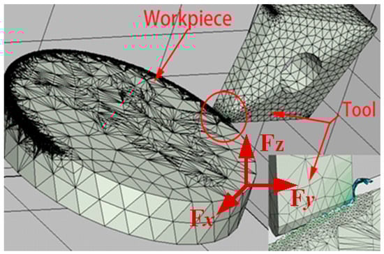
Figure 2.
Workpiece cutting tool grid division.
In the metal-cutting simulation, the material constitutive model was very important, and currently, the main constitutive models applied in metal-cutting simulation are the Power–Law constitutive model, Drucker–Prager model and User-Defined Yield Surface constitutive model. Among them, the User-Defined Yield Surface model determines the stress of the material from elasticity to plasticity under a given strain condition. The Johnson–Cook model of the selected material was invoked in this constitutive model, which is able to reflect the uneven distribution of strain, strain rate, and temperature at various locations when collision occurs during the cutting process, so this model is widely used in the cutting field [31,32]. It was assumed that the contact between the tool and the chip is sliding friction contact, and the friction coefficient between the tool and the chip was set to 0.4 during the simulation. The material model performance parameters of AISI 52100 Johnson–Cook are shown in Table 1, and the material thermo-physical properties and elastic modulus parameters are shown in Table 2.

Table 1.
Parameters of AISI 52100 Johnson–Cook material model [33].
Table 2.
Material property parameters of AISI 52100.
The yield stress in the Johnson–Cook material model is defined as:
where σ is plastic stress; A is yield strength; B is strain hardening constant; C is strain rate strengthening coefficient; m is thermal softening parameter; n is strain hardening parameter; ε is plastic strain; p is plastic strain rate; 0 is reference strain rate; t is material dynamic temperature; t0 is ambient reference temperature; tm is melting point of material.
2.2. The Result of Finite Element Analysis
We aimed to study the effect of different processing parameters such as cutting speed, feed, depth of cut on the cutting force generated during the cutting process of AISI 52100, the parameters of which are shown in Table 3.
Table 3.
Processing parameters used in finite element analysis.
Cutting Force Simulation Analysis of Cutting Process
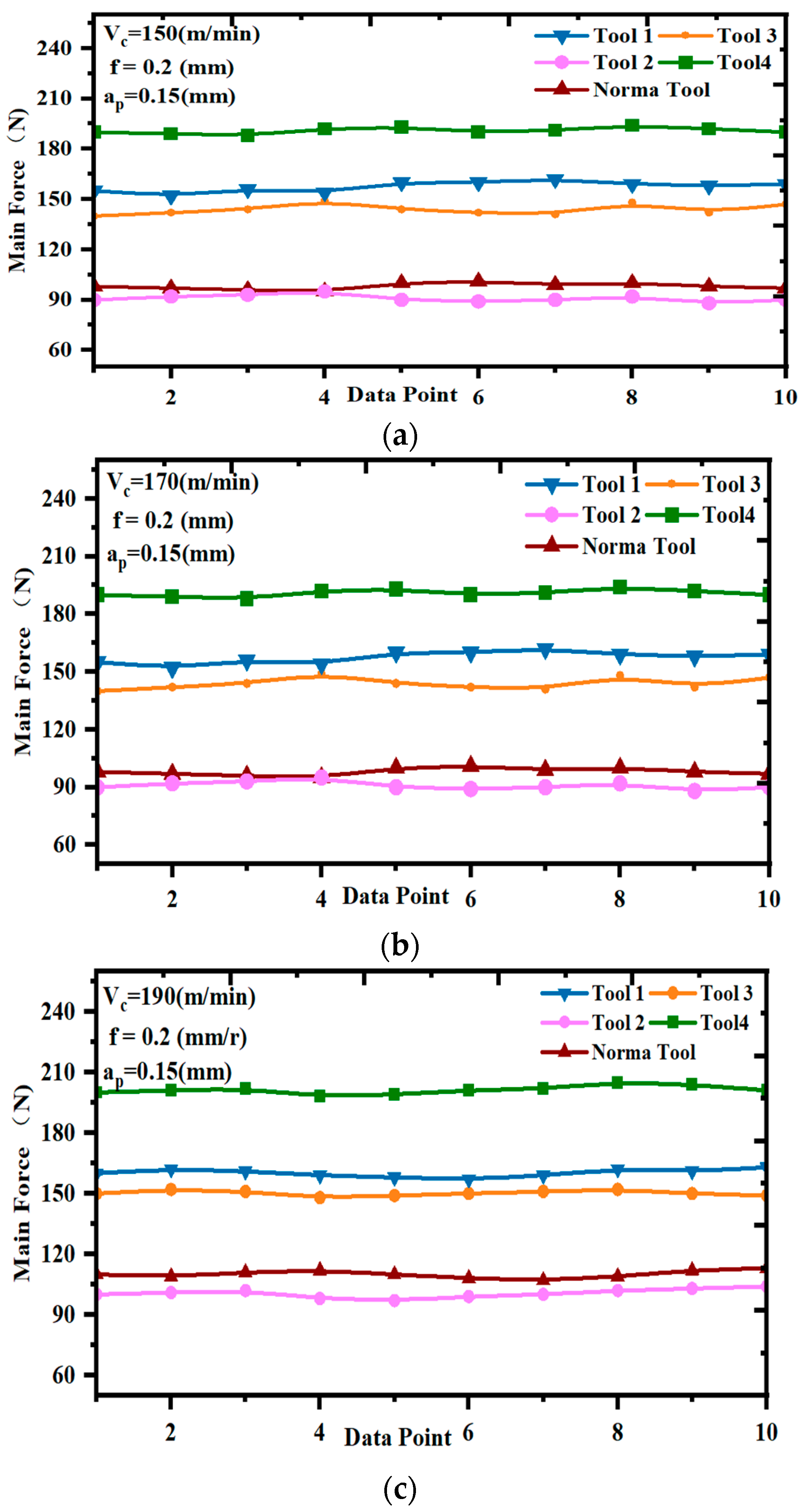
According to the finite element three-dimensional model of the bionic tool in 4 and the set parameters of the cutting dosage test, a large number of finite element simulation cutting tests were carried out. Due to the high hardness and hardness characteristics of this steel material AISI 52100, the magnitude of the cutting force in hard cutting directly affects the tool life, and so, it is particularly important to conduct a comprehensive analysis of the cutting force. In order to study the effect of machining parameters and tool structure on the main cutting force generated during the cutting process, the main cutting force generated during the cutting process was data-collected, averaged and calculated, and the fitted curves of the main cutting force of the bionic tool and the traditional structured tool under different cutting speed conditions were plotted as shown in Figure 3.
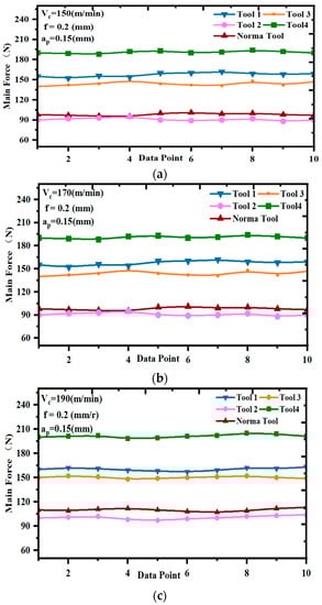
Figure 3.
Effect of cutting speed on the main cutting force of the tool. (a) vc = 150 (m/min) Influence of tool structure on main cutting forces, (b) vc = 170 (m/min) influence of tool structure on main cutting forces, (c) vc = 190 (m/min) influence of tool structure on main cutting forces.
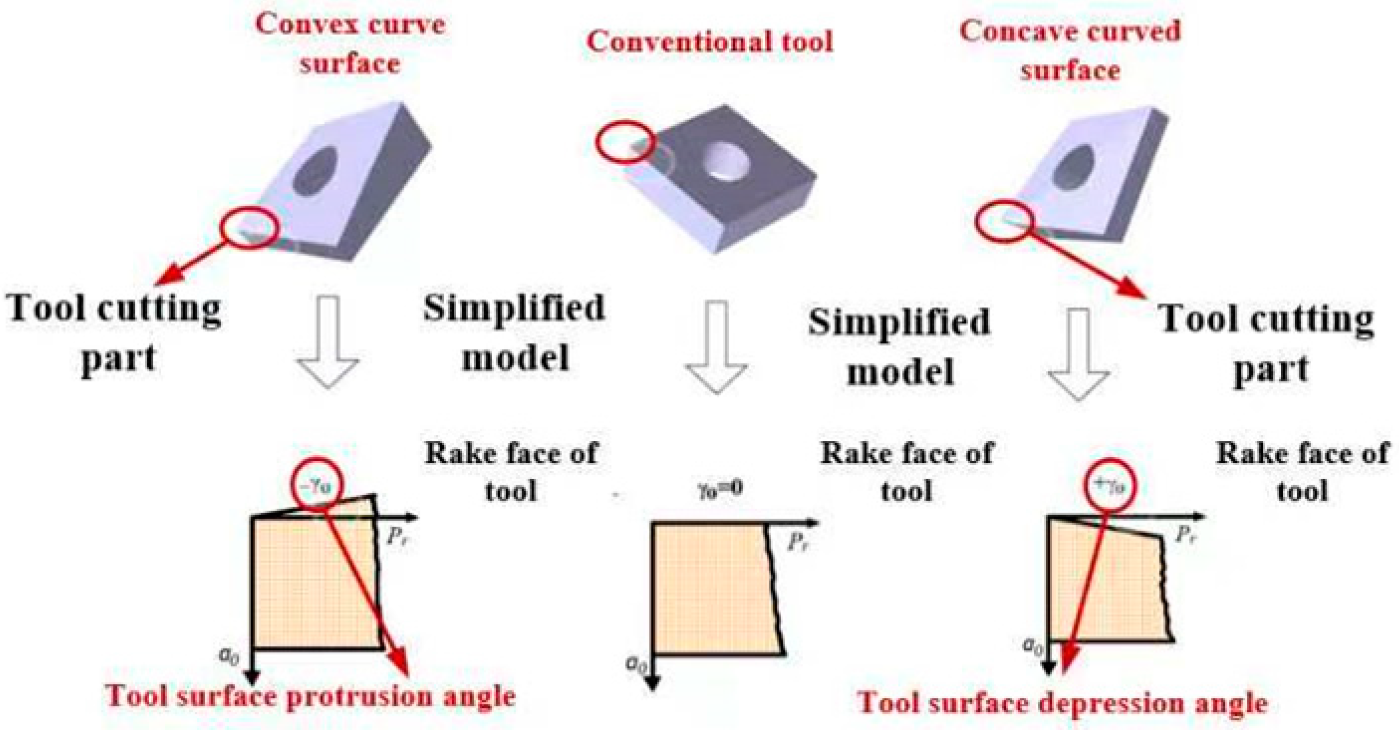
As can be seen in Figure 3, the four bionic tools had different effects on the main cutting forces. In the laboratory group 1 conditions, the main cutting force of the normal structure tool was about 85 N. The main cutting force increased obviously when using the convex plane, convex camber and concave plane tool in the test, while the main cutting force decreased by about 7% when using the concave camber tool and the cutting speed continued to climb, thus meaning that the cutting gradually increased. Figure 4 below shows the increase or decrease in the rake angle of the bionic curved face tool compared to the conventional tool. It can be seen from Figure 4 that when the concave and convex bionic tools were used for the test, the rake angle of the tool was increased and decreased relative to the normal structure tool.
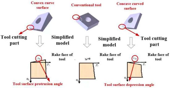
Figure 4.
Increase and decrease in tool rake angle.
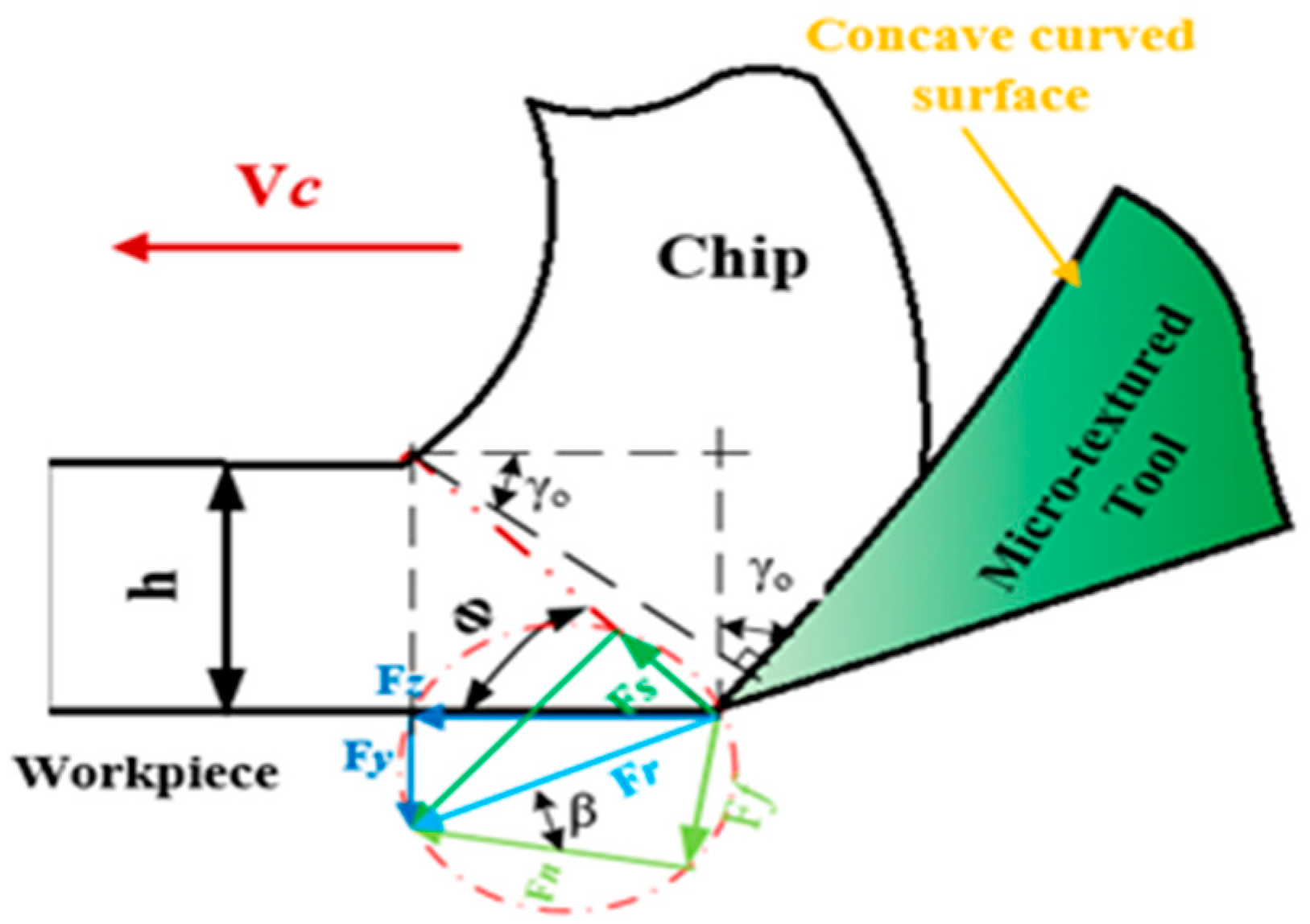
Wedge angle β0 is the angle between the rake face and the relief face, the larger the wedge angle of the cutting part of the higher strength, the greater the cutting resistance. From Formulas (2) and (3) [34], it can be seen that tool clearance angle was unchanged in its conditions, and the tool rake angle γ0 increased and the wedge angle β0 decreased. As the wedge angle β0 reduced the cutting edge tip radius, the workpiece cutting layer contact was reduced, which made the friction coefficient µ reduced.
where γ0—tool rake angle; —tool clearance angle; β0—wedge angle; β—friction angle depending on the friction coefficient of the rake face of the tool; µ—friction coefficient.
In the metal-cutting process, tool rake angle γ0 and shear angle φ affected the cutting deformation of the two major factors, according to the “tangential stress and the direction of the main stress into the 45 ° theory” of shear theory, the shear angle φ is:
where φ—shear angle.
From Equation (4), it can be seen that increasing the tool rake angle γ0 reduced the friction between the tool–chip surface, making the shear angle φ increase. Therefore, the cutting deformation was reduced, prompting a reduction in cutting force, improving the phenomenon of machine vibration during machining caused by excessive cutting force. When cutting with flat and curved face tools with the same rake angle, the curved face tool was better than the flat type tool for the suppression of the generation of the main cutting force. This is because of the unique arc structure of the rake face and the arc front tool face to promote the cutting layer of the workpiece were not in close contact with each other, reducing the tool on the cutting layer of the extrusion pressure, and the arc structure was more conducive to the flow of chips, to avoid the cutting pile up, and to contribute to the reduction in the cutting force. As the cutting speed continued to rise, the main cutting force of the tool increased. This is because as the speed rises, the material removal efficiency per unit of time rises, the workpiece cutting layer of material quickly transformed into chips to shorten the time, the chips were difficult to quickly extend the rake face out of the chip material piles up in the rake face, which can easily cause the phenomenon of the second cutting leading to an increase in the cutting force. Figure 5 below shows the angle relation of cutting tool.
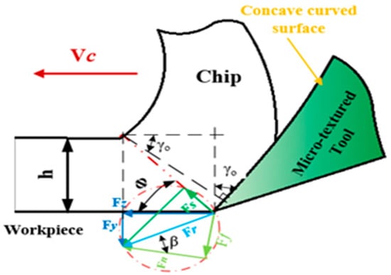
Figure 5.
Angle relation of cutting tool.
From the above analytical simulation and mathematical model analysis, it can be seen that the selection of concave curved face tool for cutting significantly alleviated the phenomenon of cutting force generation and cutting build-up, and so, the selection of concave curved face structure of the bionic tool cutting dosage for vc = 150 m/min, f = 0.2 mm/r, ap = 0.15 mm for further analysis.
2.3. Influence of Concave Camber Angle on Cutting Force
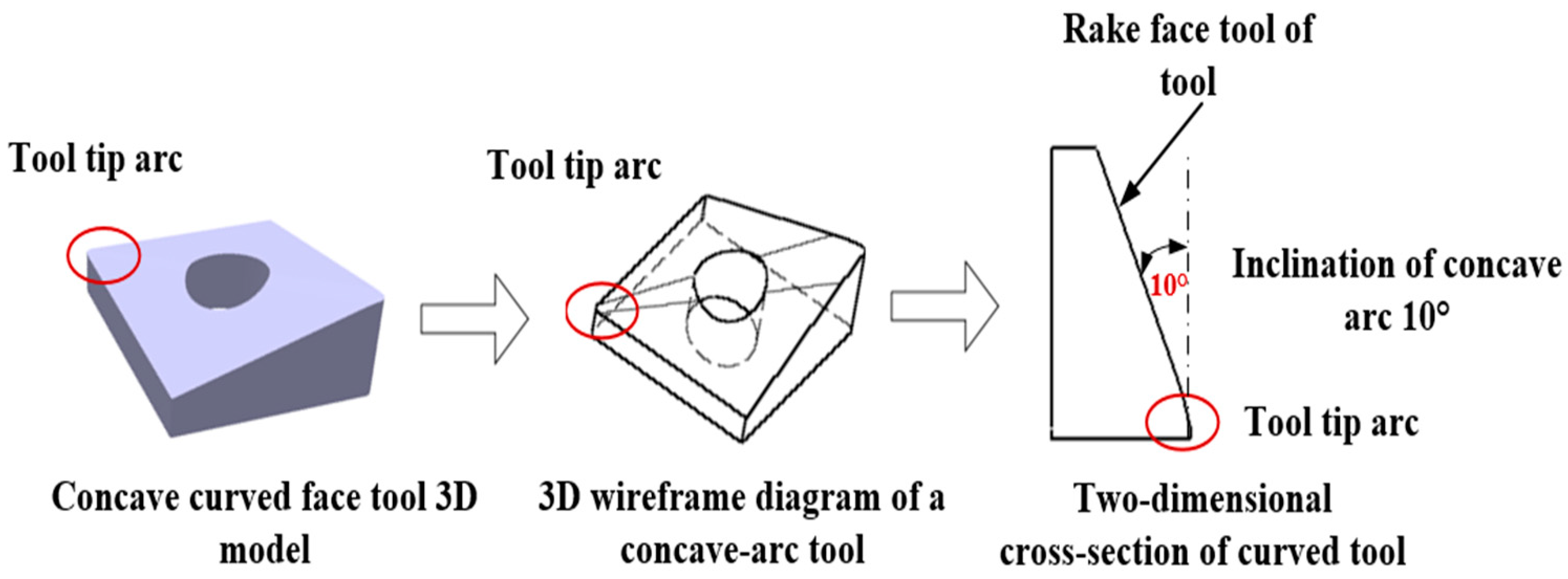
In order to investigate the optimal arc inclination angle bionic tool, based on the above test, the arc inclination angle was changed for the test, and the combination of vc = 150 m/min, f = 0.2 mm/r, ap = 0.15 mm main cutting force minimum cutting dosage was chosen to carry out the variable arc inclination angle finite element simulation test. The camber dip angles were 5°, 7°, 10°, 13°, 15° and 19°, respectively. A three-dimensional model was established and tested under the same parameters. The three-dimensional model is shown in Figure 6.
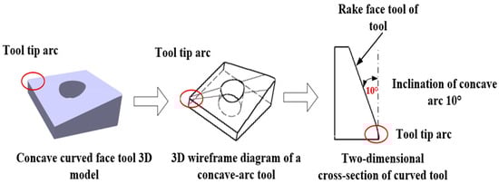
Figure 6.
Three-dimensional model of concave camber.
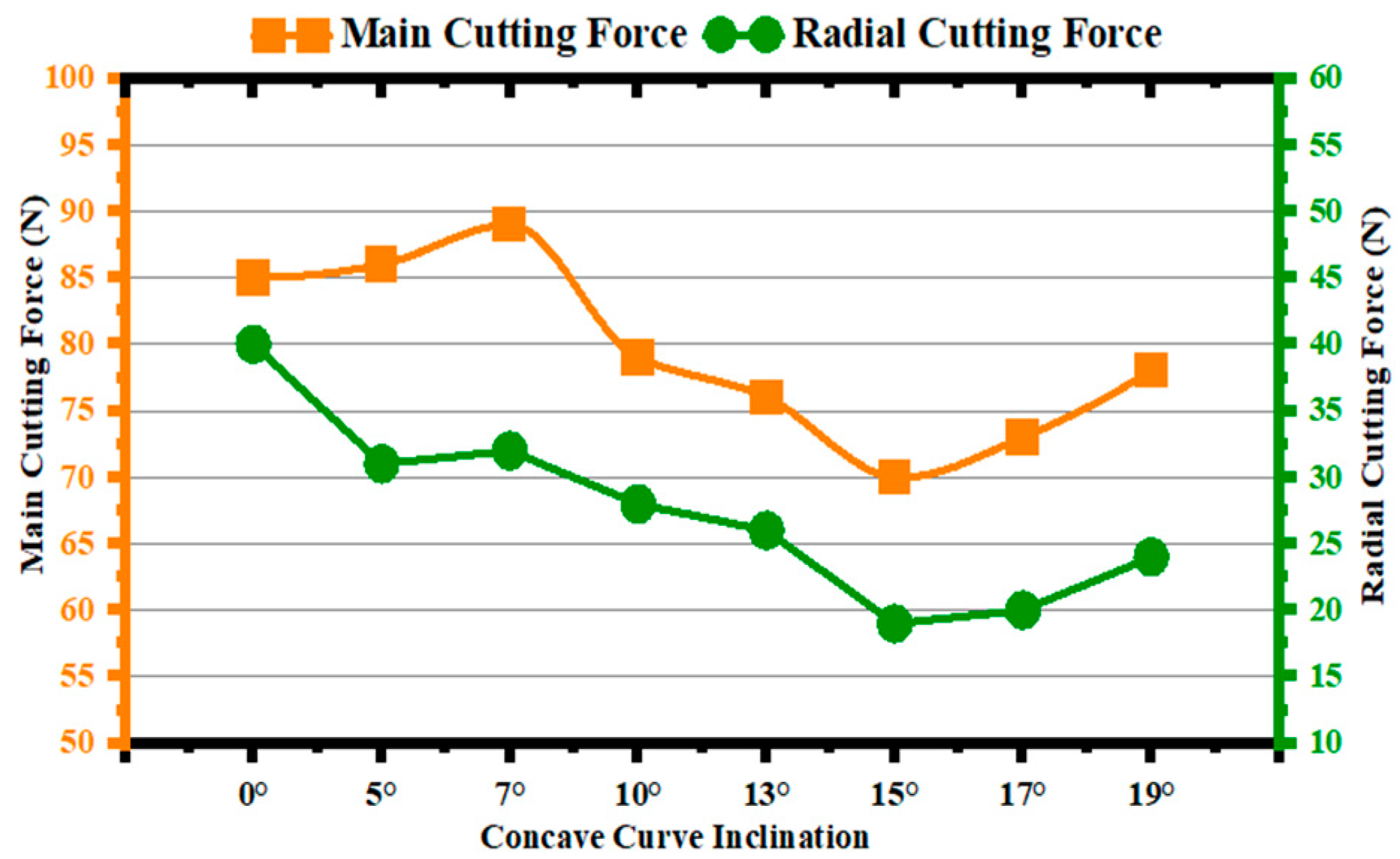
Figure 7 shows the influence of different camber angles on the main cutting force and radial force, and Figure 8 shows the force-versus-angle relationship during cutting of concave-curved surface tools. As can be seen from Figure 6, the main cutting force increased first and then decreased with the increasing dip angle, and the main cutting force reached the minimum when the camber dip angle was 15°. As can be seen from Figure 8, with the increase in the cambered angle, the radial force decreased first and then increased and reached the minimum at 15°. This is because the cutting force in cutting machining mainly comes from the frictional resistance between the workpiece-tool-chip and the force of elastic and plastic deformation inside the workpiece, and as the inclination angle of the rake face of the bionic tool continued to increase, the coefficient of friction continued to decrease, which contributed to the reduction in the cutting force. With the progress of cutting, the cutting layer was subjected to shear stress and slip phenomenon, the workpiece material broke and formed chips, and the chips flowed out of the front cutter surface and were squeezed, making the shape size of the chips change. And the degree of internal deformation of the workpiece can usually be expressed by the relative variation quantity of the chip shape Λh. According to Formula (5) [34], with the increase in the rake angle and the decrease in the shear angle, the ratio of chip compression thickness increased gradually, namely, the degree of workpiece plastic deformation increased gradually. When the inclination angle of the arc was greater than 15°, the cutting layer deformation was too large, resulting in a sharp increase in cutting force. It can be seen that when the camber angle was 15°, the bionic concave camber tool had the best cutting performance.
where Λh-chip compression thickness.
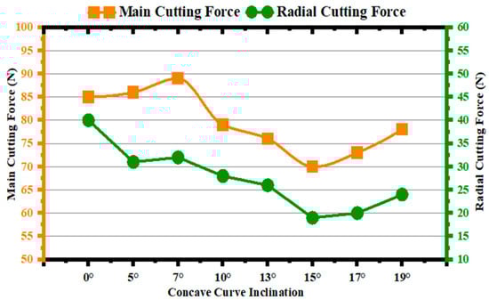
Figure 7.
Line graph of main cutting force and radial force camber angles.
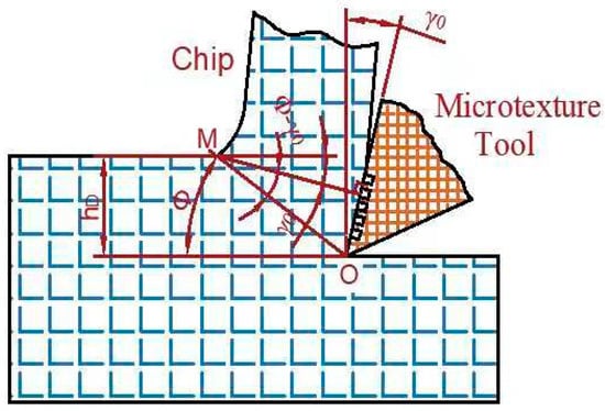
Figure 8.
Relationship between tool rake angle, shear angle and cutting deformation.
Through the analysis and comparison of the main cutting force of the tool with different structures, it can be seen that the concave-curved bionic tool had the most significant effect on reducing the main cutting force. By changing the camber dip angle, it was found that when the camber dip angle was 15°, the main cutting force and radial force reached the minimum at the same time, and the cutting performance of the tool reached the best.
3. Effect of Micro-Textured on Cutting Performance of Bionic Tool with Concave Curved Surface
Due to the rake face of the tool in the cutting process and chip contact extrusion, it was very easy to cause chip accumulation when the cutting force increased. Therefore, on the basis of the above theories, the groove-type micro texture was constructed in the tool-chip contact area to enhance the advantage of the cutting process of the concave-curved bionic tool, and to further explore the influence of the micro-texture placed in the front tool surface on the concave-curved bionic tool.
3.1. Micro-Textured Morphology and Shape Parameters
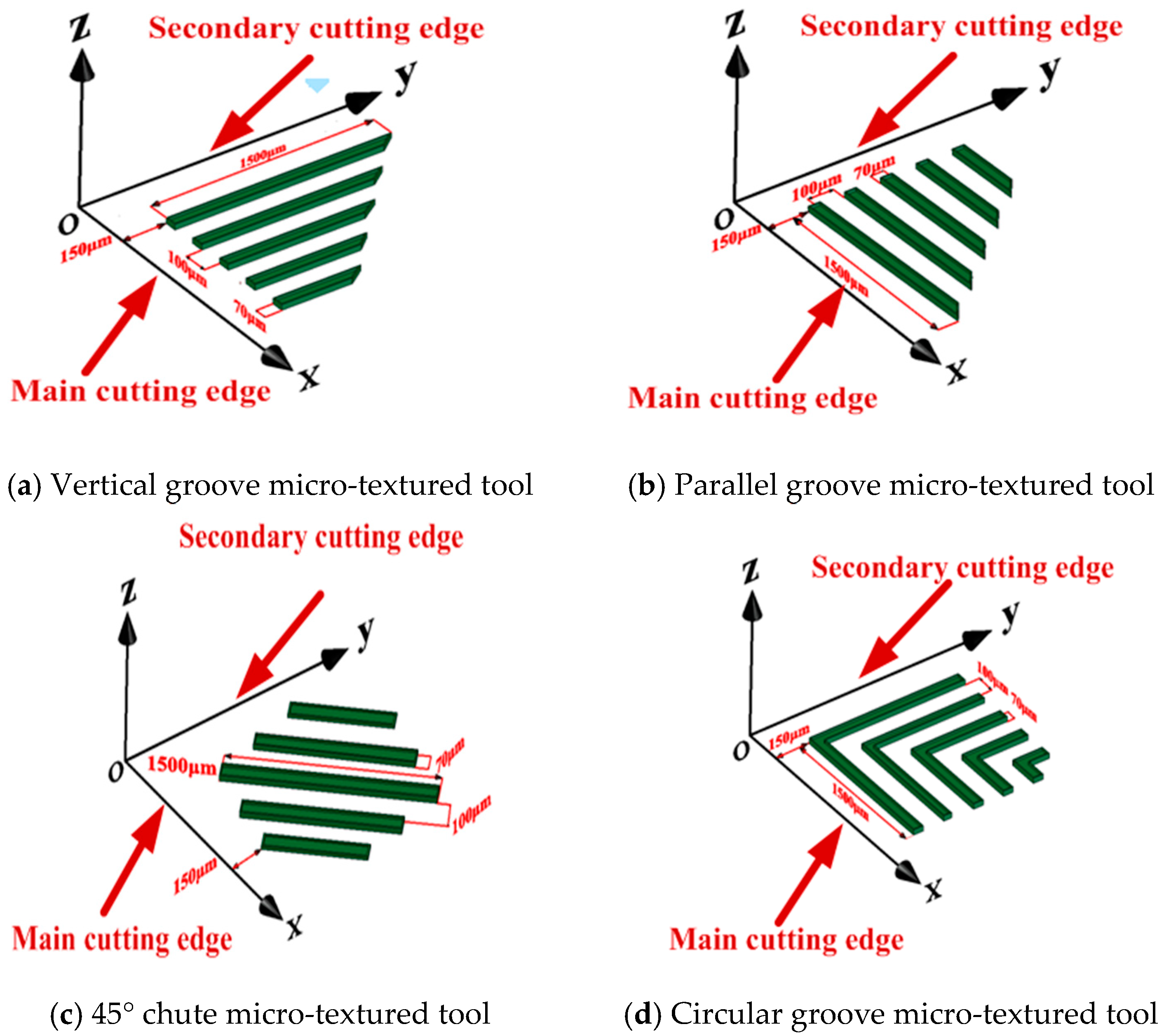
In order to analyze the influence of the micro-textured tools on the cutting performance of the tool (the four texture morphologies are shown in Figure 9), four kinds of micro-textured tools were constructed on the front cutter face of the concave bionic tool, namely, the parallel groove parallel to the main cutting edge, the vertical groove perpendicular to the main cutting edge, the circular groove parallel to the tool tip arc and the 45° chute micro-textured tool. The purpose of the modeling process was to ensure that the four structures had the same dimensions, cutting tests were carried out under the same cutting conditions, namely Vc = 150 m/min, f = 0.2 mm/r, ap = 0.15 mm, groove micro-textured spacing 100 µm, width 70 µm, length 1500 µm, depth 70 µm, edge distance 150 µm. Because the front cutter face was curved, the texture depth and width decreased with the concave degree of the front cutter face under the same dimension parameter.
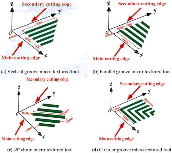
Figure 9.
Morphologies of four micro-textured tools.
3.2. Effect of Micro-Textured Type on Cutting Force
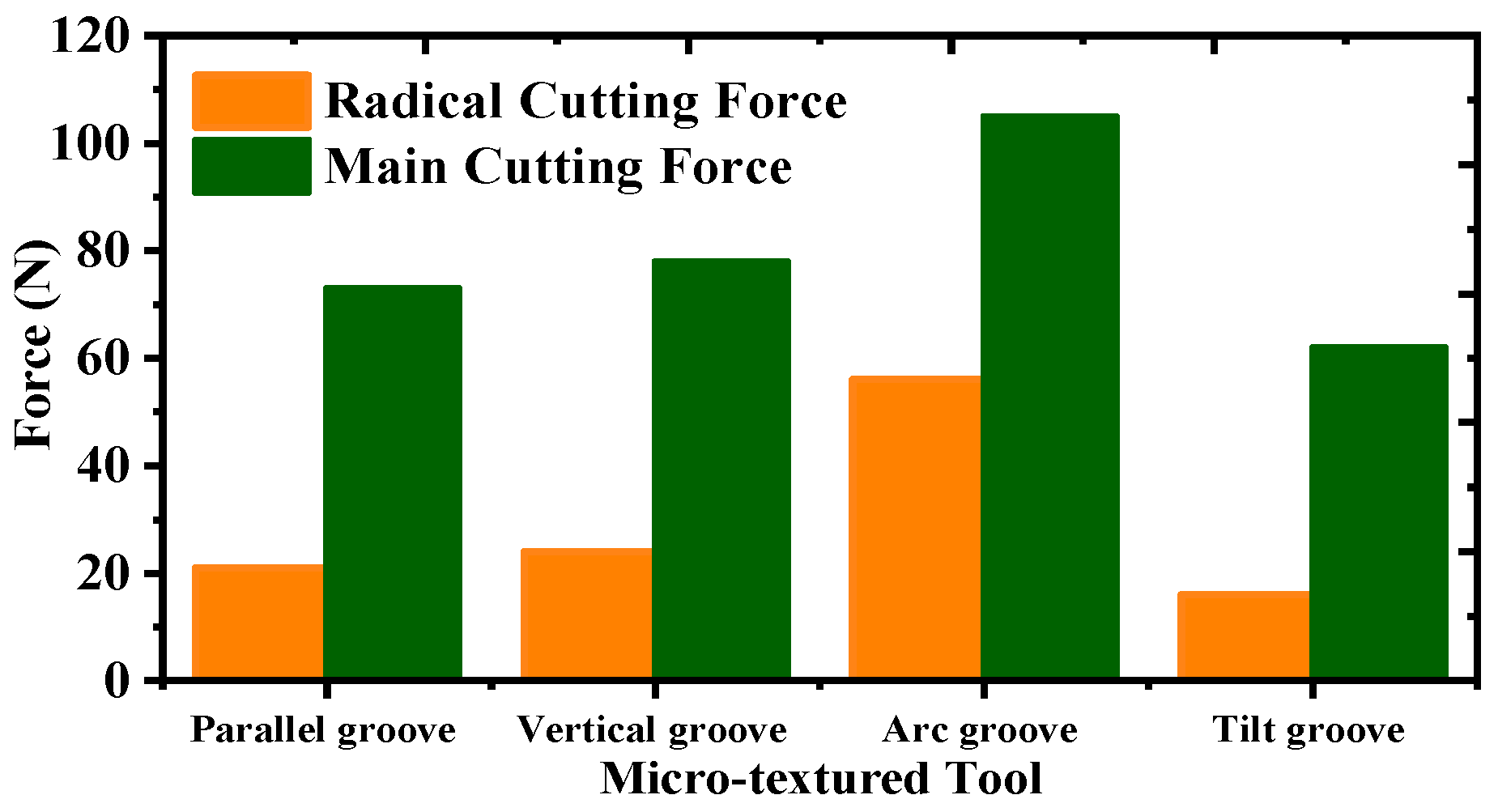
As the workpiece in the processing, the workpiece cutting layer by the tool extrusion will produce internal elastic deformation, the rake face of the tool and the workpiece material friction was intense; the rake face of the tip part of the construction of micro-textured structure can effectively alleviate the phenomenon of intense friction produced by the tool and the workpiece in close contact with the phenomenon, but the different micro-textured structure of different impacts on the cutting performance of the tool. So, this paper was on the above four kinds of micro-textured structure for finite element simulation experiments, and the cutting force simulation results are shown in Figure 10. From the figure, it can be seen that the circular groove micro-textured structure tool cutting force was the largest, the parallel groove and perpendicular groove for cutting force had a similar impact, and a 45° oblique groove to reduce the cutting force of the tool to reduce the effect was significant. In the cutting process, due to the dry-cutting tool surface and chip contact being strong, with microfabrication of the tool in the tool to increase the space between the chip, reduce the adhesion of the chip and inhibit the generation of cutting; thus, the reasonable placement of microfabrication can play a role in reducing friction and anti-wear. A 45° oblique groove weaving type tool most close to the concave arc surface bionic tool chip flow direction maximized the reduction in the tool rake face and the contact area between the chip, the cutting force and cutting temperature did not rise, and the concave arc surface knife had a larger shear angle and deformation coefficient, which can promote the chip bending and breaking during the cutting process. Chip material in the non-lubricated was also easy to enter the micro-textured parts or the chip breakage along the rake face of the knife. The chip material can easily enter the micro-textured area under non-lubrication or spill out along the rake face after chip breakage, which alleviated the phenomenon of chip accumulation.

Figure 10.
Cutting force of micro-textured concave-cambered bionic tool.
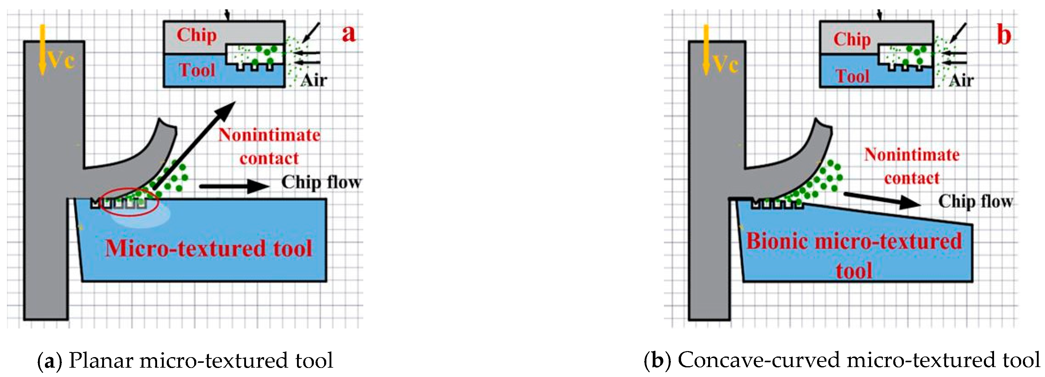
Figure 11 is a comparison chart of chip outflow between planar micro-textured tool and concave arc surface micro-textured tool. From Figure 11a, it can be seen that when the chips flowed out along the rake face of the cutter, the flow rate was very low and easy to stagnate when it was close to the surface of the rake face of the cutter, which resulted in the accumulation of chips staining the knife phenomenon. In the rake face of the tool to construct a texture, the tool entered the workpiece material extrusion cutting layer, and then the texture entered the cutting layer, and the tiny chips retained on the surface of the tool body were captured by the texture and stored inside the texture, which alleviated the phenomenon of secondary cutting. When a concave-arc-structured tool was adopted, as shown in Figure 11b, the rake face of the tool was not in close contact with the chips, which increased the chip breakout space and facilitated chip flow.

Figure 11.
Chip outflow comparison.
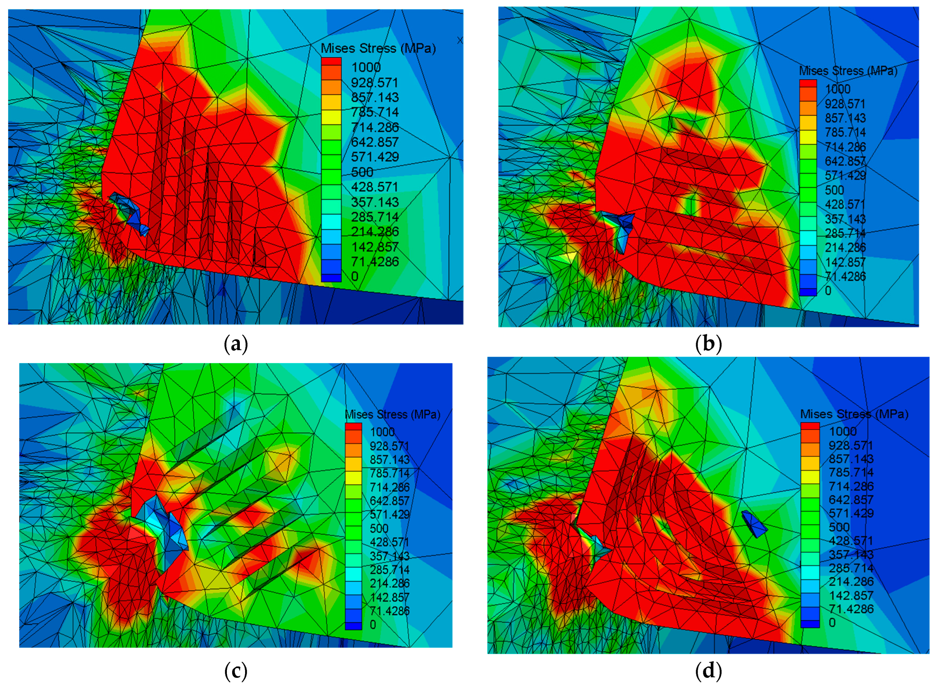
The stresses of the four tools were analyzed by finite element analysis and the stress distribution is shown in Figure 12. The maximum stress of the tool occurred in the first deformation zone, and the average stress of the four tools was 1440 MPa, 1380 MPa, 1255 MPa and 1079 MPa, respectively. According to the change of stress, the absorption and dispersion effect of the 45° chute micro-textured tool was better than the other three kinds of groove tools in the cutting process, which can promote the shear slip effect of the workpiece and facilitate the cutting of the main cutting force and radial force.
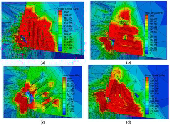
Figure 12.
Stress distribution of micro-textured tool. (a) Stress diagram of straight groove micro-textured tool, (b) stress diagram of parallel groove micro-textured tool, (c) stress diagram of 45° chute groove micro-textured tool, (d) stress diagram of circular groove micro-textured tool.
3.3. Effect of Micro-Textured Spacing on Cutting Force
Through the above analysis, it was found that 45° chute micro-textured was significantly better than the other three micro-textured tools in alleviating cutting force and promoting chip removal. Therefore, it was necessary to use quantitative analysis to explore the influence of micro-textured parameters on cutting performance. By changing the texture width on the basis of the optimal 45° chute micro-textured tool, the influence of micro-textured width on cutting performance was compared and analyzed. The dimension parameters of the 45° chute cutter with different micro-textures are shown in Table 4.
Table 4.
45° chute micro-textured spacing.
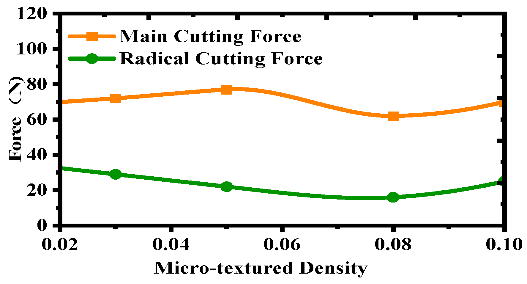
Figure 13 shows the influence of varying micro-textured width on cutting force. It can be seen from the figure that when the micro-textured spacing was 0.08 mm, the main cutting force and radial force simultaneously reached the minimum. As for the main cutting force, the main cutting force gradually increased with the increase in the spacing of micro-textured spacing, reached the peak value at 0.05 mm, and then decreased. As for the radial force, it gradually decreased with the increase in the micro-textured spacing, and then the radial force increased after reaching the minimum of 0.08 mm. This is because, on the one hand, with the increase in micro-textured spacing, the contact area between the cutter and chip increased, resulting in increased friction, resulting in a sharp increase in cutting force. On the other hand, too large micro-textured spacing will lead to part of the micro-textured layout beyond the tool–chip wear area, and the excess parts cannot play a role in anti-friction and anti-wear failure. However, if the micro-textured spacing is too small, the micro-textured will not fill the tool-chip contact area completely, and the chip capture ability of the micro-textured is weakened, which is easy to produce secondary cutting phenomenon. Moreover, the excessively small micro-textured spacing will reduce the impact resistance of the front tool face, resulting in tool wear. Therefore, the analysis found that 0.08mm was the most suitable micro-textured spacing parameter for the bionic tool with 45° chain-curved surface.
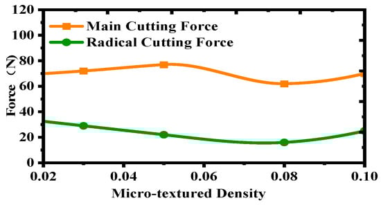
Figure 13.
Influence of micro-textured spacing on cutting force.
Through comparative analysis of four kinds of micro-textured constructed on the front cutter face of the concave camber bionic tool, it was found that the 45° chute texture was significantly better than the other three kinds of micro-textured tools in reducing cutting force, absorbing and diffusing stress, and changed the 45° chute micro-textured spacing. It was found that the cutting force was minimum at the 0.08 mm micro-textured spacing. Therefore, tools with micro-textured rake face are useful in reducing friction and material adhesion between the tool and chip interface.
4. Bionic Cutting Experiment of Coating 45° Chute Micro-Textured Concave Cambered Surface
Due to the low thermal conductivity and high hardness of the steel material, it is more likely to cause increased cutting temperatures and chip build-up and machining instability. The coated carbide tool is widely used in the finishing of steel materials because of its wear-resisting and high temperature resistance. In order to further clarify the theoretical feasibility of combining micro-textured bionic carbide cutting tool with coating technology to optimize the cutting performance of the tool, the TiN material, Al2O3 material and the combination of coating materials were used to carry out the turning simulation experiment under the condition of ensuring the same cutting dosage, to explore the influence of different coating materials on the cutting performance [35,36]. The coating was carried out on the basis of the above preferred 45° chute micro-textured bionic tool. According to the properties of the coating materials, TiN material, Al2O3 material with strong oxidation resistance and composite coating combined with the two were selected in this paper. The coating was carried out on the surface of the hard alloy, and the turning test was carried out under the same cutting conditions. The effect of coating material on machinability was studied. Figure 14 shows a flow chart of the tool-coating process.
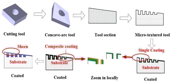
Figure 14.
Tool-Coating Flow chart.
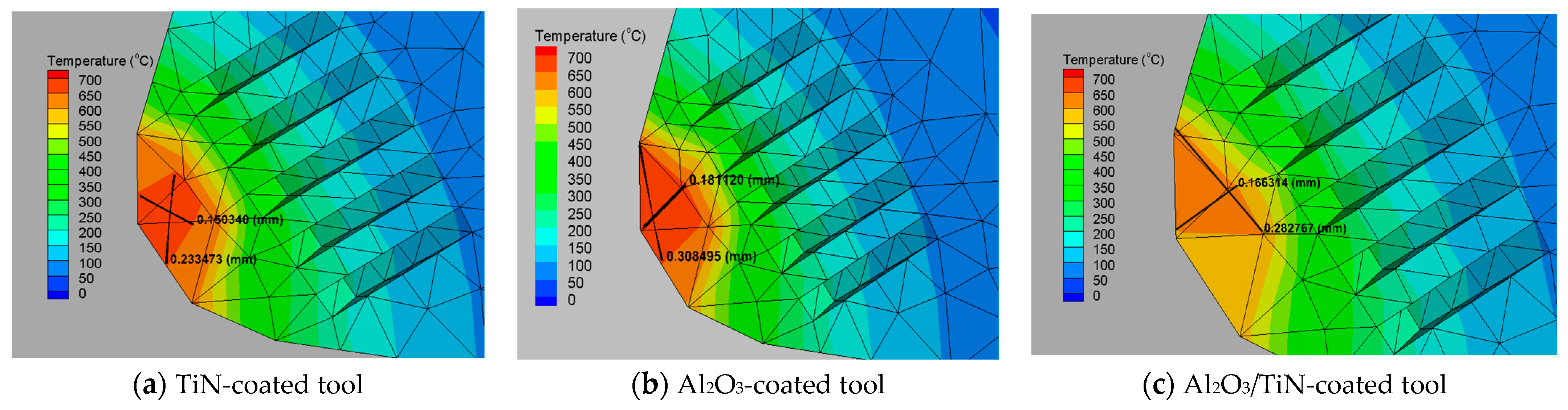
4.1. Influence of Cutting Temperature in Coated Concave-Arc Surfaces with 45° Chute Micro-Textured Bionic Tool
The cutting heat mainly comes from the elasticity and plastic deformation generated by the three deformation zones, and the friction between the chip and the front tool face, and the cutting temperature cloud is shown in Figure 15. The temperatures were 636 °C for TiN-coated tools, 655 °C for Al2O3-coated tools and 579 °C for Al2O3/TiN-composite-coated tools, indicating that composite-coated tools can reduce the cutting temperature and are better than single-coated materials. Relative to the traditional tool, the hard cutting conditions of contact but long time high temperature and high pressure state, with the micro-textured tool as the tool surface storage coating material and storage lubricant structure, can be sustained and efficient for the tool and the workpiece material in close contact with the formation of friction film in the area, and can effectively improve the lubrication state. The selected Al2O3/TiN composite coating had the characteristics of strong oxidation resistance, good heat insulation, strong bonding ability with the substrate of Al2O3 material and high hardness and strong impact resistance of TiN material at the same time. During cutting, the composite coating material was applied on the surface of the tool to form a layer of thermally stable thermal barrier between the tool and the chip with good thermal insulation effect, reducing the impact of temperature shock and friction on the structure of the tool body, thus achieving the purpose of reducing the cutting temperature, making the tool very suitable for dry cutting conditions. Due to the existence of micro-textured structure, the ability of the tool surface to capture debris was enhanced; in the wet lubrication conditions, using the chip flow along the knife surface to take away the heat, the cutting accumulation phenomenon was significantly reduced, cutting viscous and sticky, cutting temperature was reduced.
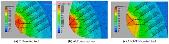
Figure 15.
Cutting heat distribution.
4.2. Effect of Cutting Speed on Cutting Force of Coating Tool
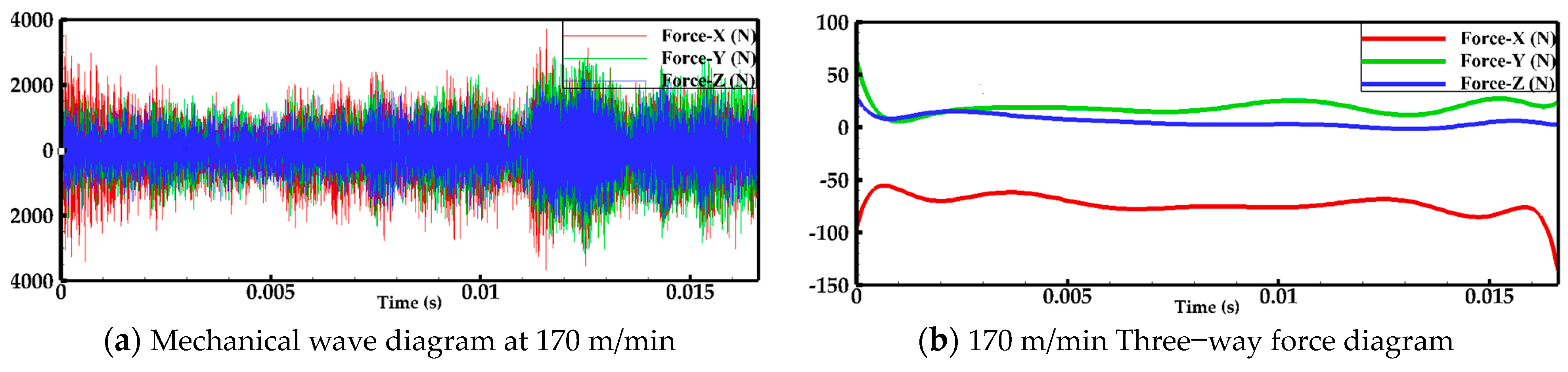
Based on the above analysis, the cutting speed was increased to study the effect of cutting speed on the performance of the coated tool. Figure 16 shows the line graph of cutting force at cutting speed 170 m/min.

Figure 16.
Cutting force.
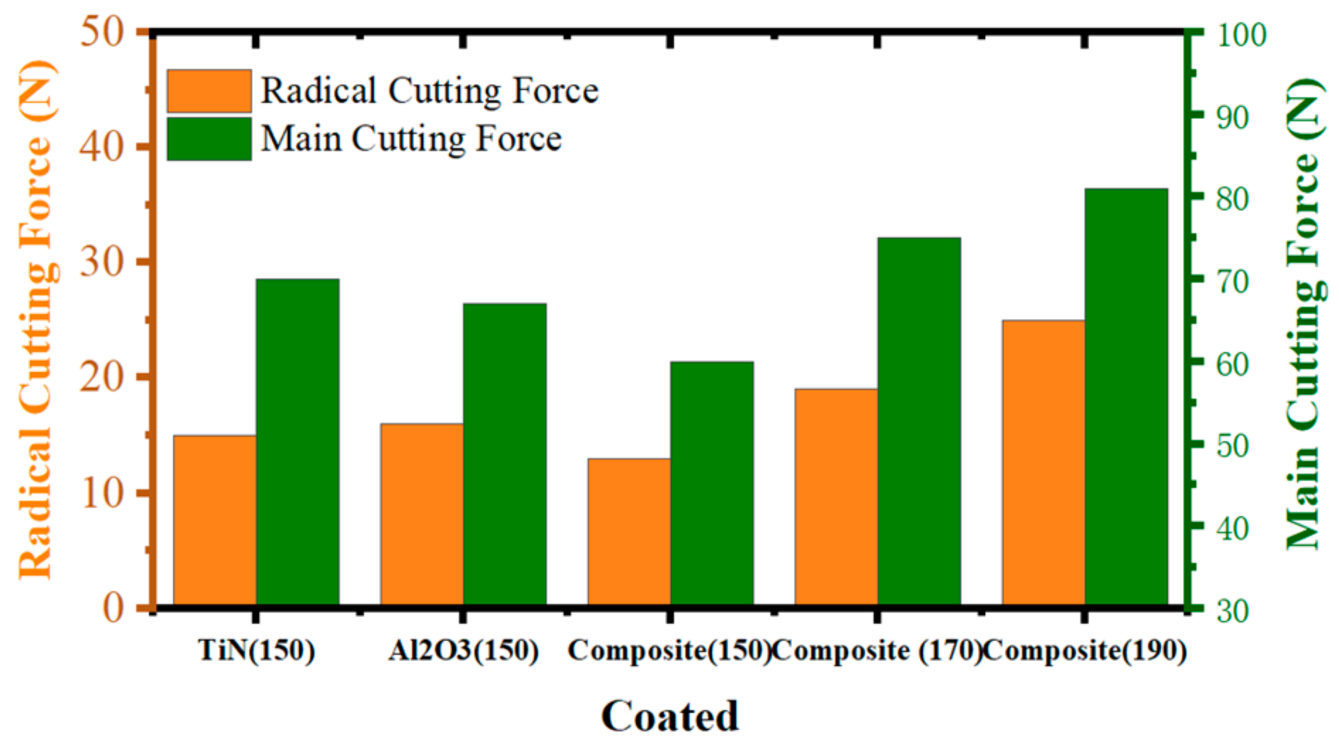
As shown in Figure 17, different cutting speeds coating material on the cutting force of the line graph were used, and Figure 18 shows the coating material and tool combination diagram. It can be seen from the figure that, under the same cutting speed, the cutting force of composite coating material was the minimum, and the cutting force increased with the increase in cutting speed. This was because the process of processing the workpiece material involved an extrusion fracture, so the chip on the front of the tool face produced a lot of pressure and friction. The coating material acted as the intermediate medium to play the role of lubrication and compression, and reduced the friction to reduce the cutting force. With the increase in cutting speed, material deformation degree and material removal rate, the cutting force and cutting temperature of the tool increased, so that the coating material on the surface of the tool body was heated to form protective film as lubricating oil, which reduced the surface retention layer chip, so that the machining stability relative to the same cutting speed without coating tool performance significantly improved. Under high-speed cutting conditions, the coating material on the tool surface was subjected to high temperature to generate aluminum oxide and titanium oxide, and the corrosion resistance of the tool was greatly improved. Composite coating materials showed a lower coefficient of friction and lower shear strength than single coating materials.
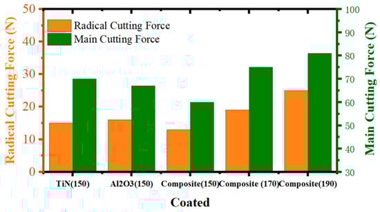
Figure 17.
Effect of coating material on cutting force.

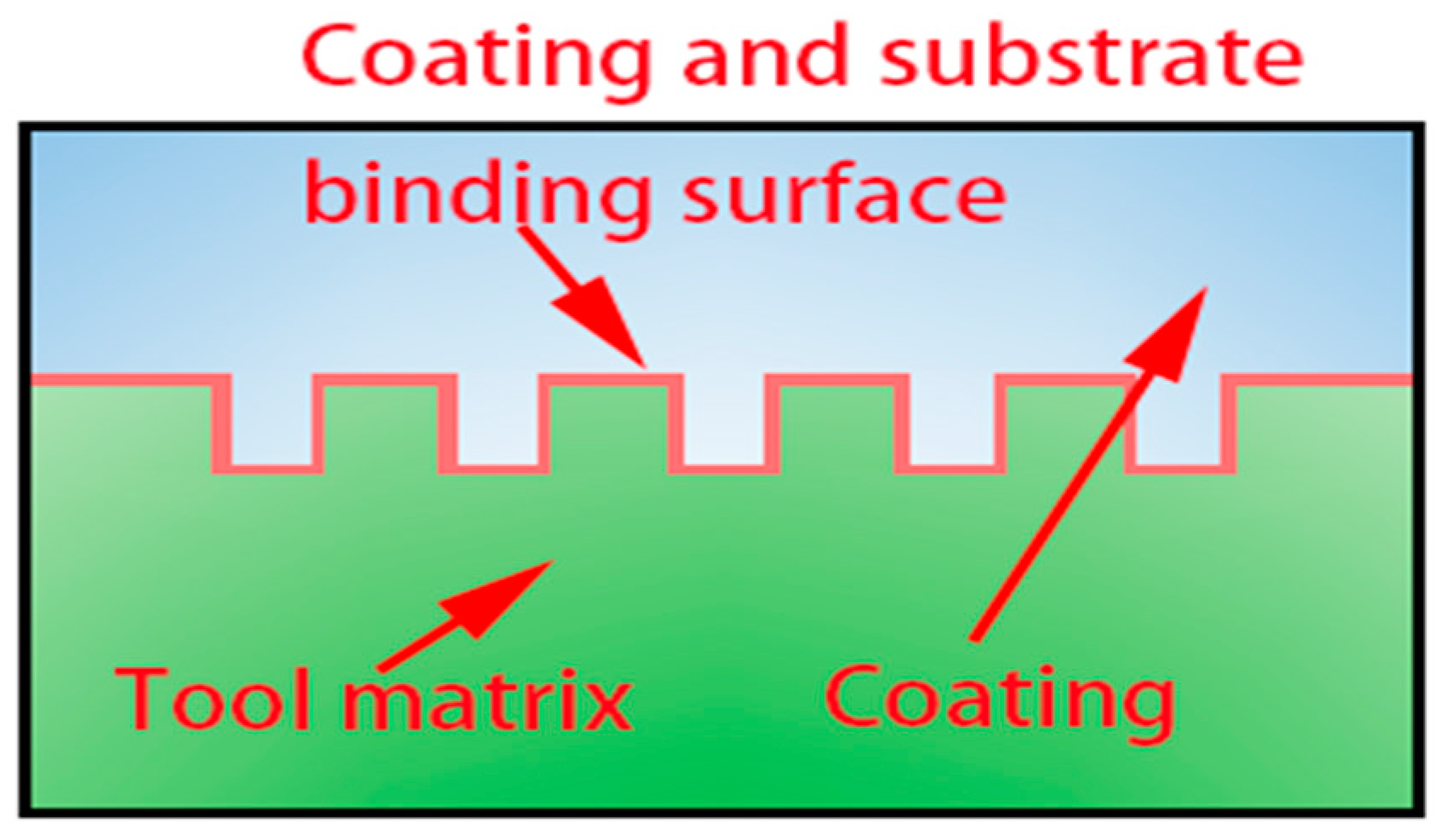
Figure 18.
Combination of coating material and tool.
Therefore, the surface coating of micro-textured bionic tool with 45° chute can effectively reduce the cutting heat and cutting force generated in the cutting process, and the composite coating material was better than the single coating tool. With the increase in cutting speed, the cutting force of composite coating tool increased gradually, but the overall cutting performance of composite coating tool was better than that of uncoated tool. Therefore, under the condition of ensuring the machining accuracy, the cutting parameters should be selected reasonably to improve the cutting efficiency. Cutting forces decreased by 45% and cutting temperatures decreased by 3.5% when machining with a composite-coated 45° slant groove micro-textured bionic tool.
5. Conclusions
In this paper, the effect of tool structure and micro-textured morphology of the rake face on the cutting performance was investigated by cutting simulation tests using bionic micro-textured tools and conventional tools. The composite coating material was applied on the surface of the bionic micro-textured tool to optimize the impact resistance of the tool, and the following conclusions were obtained:
- (1)
- When using concave arc face bionic tool cutting, experiments can inhibit the generation of cutting force, through the mathematical model and the experimental results of the analysis, concave arc face tool compared to the normal tool to increase the rake angle of the tool; in the back angle of the same conditions of the chip outflow resistance and friction coefficient were reduced; to promote the cutting chip curl fracture, leading to a reduction in cutting force, machining stability was improved. By changing the inclination angle of concave arc surface, it was found that the cutting performance of the bionic tool was optimal when the inclination angle of the arc surface was 15°, and the cutting force decreased by 29%.
- (2)
- The cutting performance of the tool was significantly enhanced when a 45° slant groove micro-textured with a micro-textured pitch of 0.08 was constructed on the rake face of the bionic tool. The combination of slant groove micro-textured and concave curved surface reduced the tool–chip adhesion area, and the chips were captured by the micro-textured site to reduce the phenomenon of secondary cutting. Moreover, the concave-curved surface of the bionic tool body caused the depth of the micro-textured to decrease with the curved surface, which protected the overall stiffness of the tool.
- (3)
- The composite coating material that prompted the cutting temperature reduction ability was more superior, and significantly improved the anti-adhesive and lubrication ability of the tool surface, so that the tool impact resistance was enhanced, and machining stability was improved. Therefore, the coated micro-textured tools should be an important direction for improving cutting performance and optimizing machining efficiency.
Author Contributions
Q.L., research ideas, experimental design and data analysis; C.M., writing manuscripts, charting, data collection.; C.W., data collection, data analysis, literature retrieval; B.W., document retrieval, data collection, research design.; S.Z., experimental design, data collection, data analysis. All authors have read and agreed to the published version of the manuscript.
Funding
Here, we need to thank the following organization for its strong support: “Natural Science Foundation of Jilin Province-General Project, Study on the Machinability of Milling Titanium Alloy with Micro-textured Milling Cutter” (20220101227JC).
Data Availability Statement
Not applicable.
Acknowledgments
The authors would like to thank the members of the project team for their dedication and efforts, and the teachers and schools for their help.
Conflicts of Interest
The authors declare no conflict of interest.
References
- Zhuang, K.; Fu, C.; Weng, J.; Hu, C. Cutting edge microgeometries in metal cutting: A review. Int. J. Adv. Manuf. Technol. 2021, 116, 2045–2092. [Google Scholar] [CrossRef]
- Zou, X.; D, J.; C, X. Process and method analysis of metal cutting precision. Sci. Wealth 2019, 36, 396. [Google Scholar]
- Cai, W.; Lai, K.H. Sustainability assessment of mechanical manufacturing systems in the industrial sector. Renew. Sustain. Energy Rev. 2021, 135, 110169. [Google Scholar] [CrossRef]
- Chowdhury, M.S.I.; Bose, B.; Yamamoto, K.; Shuster, L.S.; Paiva, J.; Fox-Rabinovich, G.S.; Veldhuis, S.C. Wear performance investigation of PVD coated and uncoated carbide tools during high-speed machining of TiAl6V4 aerospace alloy. Wear 2020, 446, 203168. [Google Scholar] [CrossRef]
- Günay, M.; Korkmaz, M.E.; Yaşar, N. Performance analysis of coated carbide tool in turning of Nimonic 80A superalloy under different cutting environments. J. Manuf. Process. 2020, 56, 678–687. [Google Scholar] [CrossRef]
- Gouarir, A.; Martínez-Arellano, G.; Terrazas, G.; Benardos, P.; Ratchev, S.J.P.C. In-process tool wear prediction system based on machine learning techniques and force analysis. Procedia CIRP 2018, 77, 501–504. [Google Scholar] [CrossRef]
- He, Z.; Shi, T.; Xuan, J.; Li, T. Research on tool wear prediction based on temperature signals and deep learning. Wear 2021, 478, 203902. [Google Scholar] [CrossRef]
- L, W. Talk about dry cutting technology. Sci. Informatiz. 2019, 2, 65. [Google Scholar]
- Wu, Z.; Yang, Y.; Su, C.; Cai, X.; Luo, C. Development and prospect of cooling technology for dry cutting tools. Int. J. Adv. Manuf. Technol. 2017, 88, 1567–1577. [Google Scholar] [CrossRef]
- Jianxin, D.; Ze, W.; Yunsong, L.; Ting, Q.; Jie, C. Performance of carbide tools with textured rake-face filled with solid lubricants in dry cutting processes. Int. J. Refract. Met. Hard Mater. 2012, 30, 164–172. [Google Scholar] [CrossRef]
- Bayraktar, S. Dry cutting: A sustainable machining technology. In Sustainable Manufacturing; Elsevier: Amsterdam, The Netherlands, 2021; pp. 231–257. [Google Scholar]
- Su, Y.; Li, Z.; Li, L.; Wang, J.; Gao, H.; Wang, G. Cutting performance of micro-textured polycrystalline diamond tool in dry cutting. J. Manuf. Process. 2017, 27, 1–7. [Google Scholar] [CrossRef]
- Niketh, S.; Samuel, G.L. Drilling performance of micro textured tools under dry, wet and MQL condition. J. Manuf. Process. 2018, 32, 254–268. [Google Scholar]
- Devaraj, S.; Malkapuram, R.; Singaravel, B. Performance analysis of micro textured cutting insert design parameters on machining of Al-MMC in turning process. Int. J. Lightweight Mater. Manuf. 2021, 4, 210–217. [Google Scholar] [CrossRef]
- Arulkirubakaran, D.; Senthilkumar, V.; Kumawat, V. Effect of micro-textured tools on machining of Ti–6Al–4V alloy: An experimental and numerical approach. Int. J. Refract. Met. Hard Mater. 2016, 54, 165–177. [Google Scholar] [CrossRef]
- Patel, K.; Liu, G.; Shah, S.R.; Özel, T. Effect of micro-textured tool parameters on forces, stresses, wear rate, and variable friction in titanium alloy machining. J. Manuf. Sci. Eng. 2020, 142, 021007. [Google Scholar] [CrossRef]
- Chen, Y.; Guo, X.; Zhang, K.; Guo, D.; Zhou, C.; Gai, L. Study on the surface quality of CFRP machined by micro-textured milling tools. J. Manuf. Process. 2019, 37, 114–123. [Google Scholar] [CrossRef]
- Li, Q.; Pan, C.; Jiao, Y.; Hu, K. Investigation on cutting performance of micro-textured cutting tools. Micromachines 2019, 10, 352. [Google Scholar] [CrossRef]
- Ma, J.; Zhang, M.; Liu, Q.; Liu, X.; Yue, C.; Yang, S. Review of bionic tool research progress. J. Mech. Eng. 2022, 58, 261–281. [Google Scholar] [CrossRef]
- Zhang, W.; Zhang, L.; Wang, B.; Wang, S. Finite element simulation analysis of bionic ball-end milling cutter. Int. J. Adv. Manuf. Technol. 2019, 103, 3151–3161. [Google Scholar] [CrossRef]
- Lian, Y.; Xie, C.; Zhou, W.; Chu, X.; Zhao, G. Study on the performance of bionic cutting tool for dry cutting GH4169 based on the surface microstructure of hemarca granosa. J. Mech. Eng. 2021, 57, 242–251. [Google Scholar] [CrossRef]
- Duan, R.; Deng, J.; Lei, S.; Ge, D.; Liu, Y.; Li, X. Effect of derivative cutting on machining performance of micro textured tools. J. Manuf. Process. 2019, 45, 544–556. [Google Scholar] [CrossRef]
- Szczotkarz, N.; Mrugalski, R.; Maruda, R.W.; Królczyk, G.M.; Legutko, S.; Leksycki, K.; Dębowski, D.; Pruncu, C.I. Cutting tool wear in turning 316L stainless steel in the conditions of minimized lubrication. Tribol. Int. 2021, 156, 106813. [Google Scholar] [CrossRef]
- Behera, B.C.; Setti, D.; Ghosh, S.; Rao, P.V. Spreadability studies of metal working fluids on tool surface and its impact on minimum amount cooling and lubrication turning. J. Mater. Process. Technol. 2017, 244, 1–16. [Google Scholar] [CrossRef]
- Sousa, V.F.; Silva, F.J. Recent advances in turning processes using coated tools—A comprehensive review. Metals 2020, 10, 170. [Google Scholar] [CrossRef]
- Mohanty, A.; Gangopadhyay, S.; Thakur, A. On applicability of multilayer coated tool in dry machining of aerospace grade stainless steel. Mater. Manuf. Process. 2016, 31, 869–879. [Google Scholar] [CrossRef]
- Zheng, G.; Zhao, G.; Cheng, X.; Xu, R.; Zhao, J.; Zhang, H. Frictional and wear performance of TiAlN/TiN coated tool against high-strength steel. Ceram. Int. 2018, 44, 6878–6885. [Google Scholar] [CrossRef]
- Panda, A.; Sahoo, A.K.; Kumar, R.; Das, R.K. A review on machinability aspects for AISI 52100 bearing steel. Mater. Today Proc. 2020, 23, 617–621. [Google Scholar] [CrossRef]
- Sharma, N.; Gupta, K. Influence of coated and uncoated carbide tools on tool wear and surface quality during dry machining of stainless steel 304. Mater. Res. Express 2019, 6, 086585. [Google Scholar] [CrossRef]
- Fan, L.; Deng, Z.L.; He, Y.; Zhu, X.L.; Gao, X.J.; Jin, Z. The effects of micro-texture shape on serrated chip geometry in the hardened steel AISI D2 cutting process. Surf. Topogr. Metrol. Prop. 2022, 10, 015031. [Google Scholar] [CrossRef]
- Weilin, C.; Dong, Y.; Min, W.; Ma, H. Simulation study on right-angle cutting of 7050-T7451 aluminum alloy. Mech. Manuf. 2021, 59, 63–67. [Google Scholar] [CrossRef]
- Hongbo, P.; Hongjian, Z. Research progress on the intrinsic structure model of metallic materials. Mech. Eng. Mater. 2012, 36, 5–10+75. [Google Scholar]
- Zheng, K.; Yang, F.; Pan, M.; Zhao, G.; Bian, D. Effect of surface line/regular hexagonal texture on tribological performance of cemented carbide tool for machining Ti-6Al-4V alloys. Int. J. Adv. Manuf. Technol. 2021, 116, 3149–3162. [Google Scholar] [CrossRef]
- Liu, P.D.; Duan, J.Y. (Eds.) Metal Cutting Principles and Tools (TG501;TG71); Jilin University Press: Jilin, China, 2016. [Google Scholar]
- Xin, T.; Pei, H.; Shucai, Y. Coating and micro-texture techniques for cutting tools. J. Mater. Sci. 2022, 57, 17052–17104. [Google Scholar] [CrossRef]
- Xiang, D.; Feng, H.; Guo, Z.; Zhang, L.; Wu, B. Preparation technology and properties of microtexture diamond-coated tools. Int. J. Refract. Met. Hard Mater. 2018, 76, 16–24. [Google Scholar] [CrossRef]


Disclaimer/Publisher’s Note: The statements, opinions and data contained in all publications are solely those of the individual author(s) and contributor(s) and not of MDPI and/or the editor(s). MDPI and/or the editor(s) disclaim responsibility for any injury to people or property resulting from any ideas, methods, instructions or products referred to in the content. |
© 2023 by the authors. Licensee MDPI, Basel, Switzerland. This article is an open access article distributed under the terms and conditions of the Creative Commons Attribution (CC BY) license (https://creativecommons.org/licenses/by/4.0/).