Abstract
Ergonomics is a key factor in the improvement of health and productivity in workplaces. Its use in improving the performance of a manufacturing process and its positive effects on productivity and human performance is drawing the attention of researchers and practitioners in the field of industrial engineering. This paper proposes an ergonomic design approach applied to an innovative prototype of an adaptive automation assembly system (A3S) equipped with Microsoft Kinect™ for real-time adjustment. The system acquires the anthropometric measurements of the operator by means of the 3-D sensing device and changes its layout, arranging the mobile elements accordingly. The aim of this study was to adapt the assembly workstation to the operator dimensions, improving the ergonomics of the workstation and reducing the risks of negative effects on workers’ health and safety. The case study of an assembly operation of a centrifugal electric pump is described to validate the proposed approach. The assembly operation was simulated at a traditional fixed workstation and at the A3S. The shoulder flexion angle during the assembly tasks at the A3S reduced between 18% and 47%. The ergonomic risk assessment confirmed the improvement of the ergonomic conditions and the ergonomic benefits of the A3S.
1. Introduction
The performance of an industrial company, in terms of productivity, is often affected by the occurrence of work-related musculoskeletal disorders (WMSDs) and psychological stress among workers [1,2]. To reduce these adverse effects on workers’ health and safety and reach acceptable levels of work effectiveness, several industrial companies are currently designing and redesigning physical workspaces as well as the overall production system according to ergonomic principles [3,4]. In the late 1990s, researchers and industrial practitioners used videotaping systems to collect information that was useful for the improvement of ergonomic design and to monitor human workers performing manufacturing operations [5,6,7]. In these studies, authors analyzed the videotapes and implemented a trial-and-error methodology to improve the workstation ergonomic design [5,6,7]. This trend proves that, in most cases, the phases of data collection and ergonomic adjustment of the manufacturing system are not performed in real time. Very few studies propose real-time applications for the ergonomic design of such systems. Three-dimensional sensing devices, such as Vicon cameras and Microsoft Kinects™ systems with multiple cameras, can be used for human body tracking and to make the manufacturing system able to acquire the anthropometric measurements of the body in real time and consequently reconfigure its structure [8,9]. Microsoft Kinect™ is a motion sensing device originally created as a camera for the gaming system Xbox and is able to provide real-time skeletal tracking in a three-dimensional space through an RGB camera, an infrared projector and a monochromatic C-MOS sensor [10]. Compared with traditional electromagnetic-based and opto-electronic motion tracking systems, the Kinect sensor is very low-cost, portable and marker-less [11,12]. The existing laboratory-based 3-D motion capture systems are of limited use to perform ergonomic assessment. Both active, e.g., NDI, and passive, e.g., Vicon Motion Systems, video-based systems are not easy to use in real-world applications due to complexity and space requirements, while magnetic tracking systems, e.g., Polhemus, and inertial measurement systems, e.g., Xsens, tend to have limited accuracy [13]. The Kinect sensor offers portable 3-D motion capture capabilities that overcome the limitations of the existing systems, and thanks to its above-mentioned characteristics, it can be efficiently used for human body tracking and for ergonomic risk assessment. Beyond such advantages and benefits, the Kinect system is suitable to be used in small capture volumes and, preferably, in indoor environments characterized by light brightness. These two factors are among the main limitations of this system.
This paper proposes an ergonomic design approach applied to an innovative prototype of an adaptive automation assembly system (A3S), which has risen in the last few years as an Industry 4.0 solution, able to cope with product variety and production efficiency [14]. The proposed A3S prototype is equipped with Microsoft Kinect™ for real-time adjustment. The system acquires the anthropometric measurements of the operator through the 3-D sensing device and changes its layout, arranging the mobile elements accordingly. The aim is to adapt the workstation to the worker dimensions, improving the ergonomics of the workstation and reducing the risk of biomechanical overload and awkward postures for assembly workers. A case study of an assembly of a centrifugal electric pump is used to validate the proposed approach. According to this background, the remainder of this paper is organized as follows: Section 2 introduces a literature review on the ergonomic approach to the design of work systems, while Section 3 describes the A3S prototype and the logical control that drives the adaptation of the workstation layout to the characteristics of the assembly operator. The case study on the assembly operation of an electric pump is described in Section 4. Finally, Section 5 and Section 6 describe the results of the case study and the future developments of this research.
2. Literature Review
Ergonomics is a key factor in the improvement of health and productivity in workplaces. Past and recent studies widely investigated the impact of ergonomics and human factors on the design of workplaces and work processes in all industries. The use of ergonomics to improve the performance of a manufacturing process and the positive effects of ergonomic design on productivity and human performance are drawing attention from researchers and practitioners in the field of industrial engineering, i.e., ergonomics can optimize human performance and overall work system performance [15]. Furthermore, ergonomic workplaces and jobs reduce injury and absenteeism rates while improving productivity, quality and reliability [16].
The design of work systems needs to consider the interactions among one or more workers and the components of the system, such as tasks, equipment, workspace and environment. Finnsgard et al. [17] examined how the materials’ exposure on the workstation impacts performance in terms of non-value-adding work, space requirements and ergonomics. Three workstations in the assembly line of an automotive company were studied and redesigned following the principles of lean production, using smaller plastic containers for the materials’ exposure. After the redesign, the ergonomic improvement for the assembly operator was significant, with a 92% reduction in potentially harmful picking activities. In addition, the space required for materials was reduced by 67%, non-value-adding work decreased by 20%, and walking distance was reduced by 52%.
Botti et al. [18,19] developed a mathematical model for the design of ergonomic lean processes in assembly lines with both workers and automated machinery. The aim was to improve ergonomics for manual workers and cost reduction for the whole assembly process, following the principles of lean manufacturing. Results showed that worker ergonomics is a key parameter of the assembly process design, as other lean manufacturing parameters, e.g., takt time, cycle time and work in progress.
The redesign of a workstation to meet the ergonomic principles and to obtain the related improvements requires the analysis of the characteristics of workers and the workplace, aiming to identify potential issues that need to be addressed. In their study, Kushwaha and Kane [20] proposed the redesign of a crane cabin from the 1960s, aiming to fit man and machine to improve the worker’s performance and reduce stresses and fatigue at work. After a first analysis of the workplace and a preliminary ergonomic risk assessment, the authors investigated the anthropometric data of the workers required to use the crane cabin and redesigned the workplace. The results of their study showed that the intervention of ergonomics in the workplace reduced the mismatch between man and machine and made the workplace comfortable for work.
Regulations and International Standards establish the fundamental principles of ergonomics for executives, managers, workers (and their representatives, when appropriate) and professionals, such as ergonomists, project managers and designers who are involved in the design or redesign of work systems. The ISO 45001 standard on safety management systems plays a crucial role in supporting employers in improving occupational health and safety in their workplaces [21]. This standard enables employers to anticipate and prevent risks, protecting the health of their employees [22]. Additionally, ISO 45001 promotes the consideration of potential adverse impacts on employee health and safety in global supply chains, ensuring that hazards in outsourced processes are controlled [23]. Work system design considers human beings as the main factor and an integral part of the system to be designed, including the work process as well as the work environment [24]. This approach, known as human-centred design, enhances the effectiveness and the efficiency of the work system while improving human well-being, user satisfaction, accessibility and sustainability and counteracting possible adverse effects of use on human health, safety and performance [25]. Specifically, ISO 9241:2010 [25] identifies four linked human-centred design activities that shall be addressed during the design of a working system: understanding and specifying the context of use, specifying the user requirements, producing design solutions, and evaluating the design. The development of human-centred design activities does not imply a strictly linear process, i.e., each human-centred design activity uses outputs from other activities.
The International Standard ISO 6385:2016 [24] describes an integrated approach to the design of work systems, where ergonomists cooperate with other professionals involved in the design, with attention to the human, social and technical requirements. Work organization, work tasks, jobs, work environment, work equipment and workstation should be designed considering the interdependencies among them. When designing machinery and work tasks, the designer shall consider the differences and the dynamic characteristics of the intended population [26].
Specifically, ISO 6385 requires including considerations of body dimensions, posture, muscular strength and movement during the design of workstations and work equipment, e.g., sufficient space should be provided to allow the task to be performed with good working postures and movements, opportunities for variations in posture and to allow easy access [24]. Professionals who are involved in the design of work systems consider the human body measurements for technological design established by ISO 7250-1 [27]. The list of anthropometric measurements specified in ISO 7250-1 is a guide for ergonomists who are required to define body measurements for population groups and apply the ergonomics principles to the geometric design of workplaces and living environments. However, body measurements of people have been increasing in many countries over the last decades, and the rate of increase differs from country to country. The ISO/TR 7250-2 [28] provides statistical summaries of body measurements for working-age people in the national population. To meet the goals of the human-centred design, ISO 14738 [29] establishes principles for deriving working area dimensions, e.g., working surface height, working area limits and space requirements for legs and feet, from anthropometric measurements and applying them to the design of workstations at non-mobile machinery.
Recent studies investigated the use of 3-D systems, motion capture systems and other innovative technologies to monitor working movements and postures and to retrieve data for workplace ergonomic risk assessment [30,31,32,33,34]. Recent analyses examined job performance using digital human models created by digitally recording the movements of actual workers through keyboard- and mouse-based data input [18,19,35,36]. However, this approach requires time to model all movements, and accuracy depends on the modelling technician [33]. To address these issues, Jun et al. [33] developed a digital human modelling automation system to model human movements, adopting an active sensing method with wearable sensors and a passive sensing method with cameras. The authors analyzed the data obtained with two different cameras, i.e., a Vicon camera and a Microsoft Kinect™ system with multiple cameras. Results show that using a Vicon camera allows one to quickly and accurately model movements, although the cost of the camera is high. However, Kinect cameras are cost-effective gaming devices that offer interesting possibilities in the context of biomechanical research and clinical applications [11,36]. Several studies have investigated the limits of such motion capture systems [32,33]. Although performance differences for various movements and motion planes have been found, previous researchers suggest that the Kinect is a viable tool for general biomechanical research, with specific limits on what levels of performance can be expected under various conditions [36].
Previous researchers investigated the design of adjustable workstations to accommodate users with different body dimensions. Nanthavanij [37] proposed a body height–workstation setting matrix for the adjustment of ergonomic visual display terminal (VDT) workstations with adaptable features. Specifically, the matrix gathers the results of a computational algorithm [38] that estimates relevant body measurements and retrieves the workstation settings, e.g., seat level height, keyboard’s home row level height, keyboard distance (shoulder to home row), screen centre level height, and screen centre distance (back rest’s plane to screen). Office workers use two parameters, the user’s body height and sex, to investigate the matrix and to estimate recommended workstation settings based on ergonomics principles. Nanthavanij’s study assumes that the workstation has adjustable features. However, workstations in the industry are frequently designed in an arbitrary manner, with fixed features and giving little consideration to the anthropometric measurements of the anticipated user [5,39,40,41].
Jung [42] developed a prototype of an adjustable table and an adjustable chair for educational institutions to meet the increasing physical dimensions of students. The adjusting mechanism on the table allows the user to set the surface height to the elbows in a sitting position. Similarly, the chair legs and the backrest can be adjusted to ensure proper posture and comfort for students. Delleman and Dul [43] investigated the design of a traditional sewing machine workstation with ten different combined adjustments of table height, desk slope, and pedal position. Working posture and workers’ perceptions were measured. The authors formulated a set of recommendations on table height and slope, aiming to minimize the load on the musculoskeletal system during sewing operation.
Workstation adjustment should take place every time that a worker moves to a workstation that is not designed to meet his or her dimensions. However, such an activity requires time and effort. Brkic et al. [44] proposed a methodology for the ergonomic assessment of crane cabins through kinematic modelling. The results suggested changes to existing standards to improve safety.
The analysis of the literature highlighted the presence of a wide set of papers proposing methods and algorithms to best design and manage production systems ergonomically in a wide range of industries. However, papers proposing full-scale prototypes addressing ergonomic issues and ready to be applied in a wide set of manufacturing industries are missing but highly expected.
This paper introduces the ergonomic design of an A3S prototype equipped with a 3-D sensing device for real-time adjustment. The system acquires the anthropometric measurements of the operator through the 3-D sensing device, i.e., Microsoft Kinect™, and changes its layout, arranging the mobile elements accordingly. An ergonomic risk assessment was performed to assess the risk due to the repetitive movements required to perform the manual activities at the reference workstation. The proposed assembly layout is suitable for a large set of industries, i.e., it is not designed for a specific sector, and manufacturing small- or medium-sized products, proving the reproducibility of the method.
The following Section 3 introduces the materials and the methods adopted in this study, together with the layout of the A3S and the limitations of the adopted approach.
3. Materials and Methods
3.1. Adaptive Automation Assembly System (A3S) Prototype
The system in Figure 1 is the adaptive automation assembly system (A3S) prototype equipped with a 3-D sensing device for real-time adjustment. The system acquires the anthropometric measurements by means of such a device and arranges the mobile elements of the assembly workstation accordingly. The aim is to adapt the workstation features to the body dimensions of the operator, reducing the risks of biomechanical overload and awkward postures and improving the workers’ health and safety.
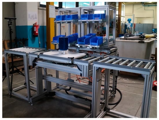
Figure 1.
Adaptive automation assembly system prototype (A3S).
Figure 2 outlines the components of the A3S. The workstation is made of three roller conveyors and a metallic frame. These conveyors are in central and lateral positions, and each workpiece is located on the roller conveyor during assembly. The metallic frame includes two movable modules (1) and a common base structure. The role of the two modules is to host the boxes with the assembly parts and components. Specifically, each module has an empty volumetric skeleton with two conveyors tilted at 12 degrees. These two modules move along the two Cartesian axes parallel to the ground, opening and closing symmetrically—lateral extension (LE in Figure 2)—and moving toward the operator—frontal extension (FE in Figure 2)—to ease the component pick. This mechanism reduces the operator movements and, consequently, the picking time. Two screw–nut groups, driven by two motors, are placed in the upper part of two extendable supports (2) and allow the vertical extension (VE in Figure 2) of the main roller conveyor (4). The two lateral roller conveyors (3) are placed on each side of the main roller conveyor and allow the product workflow on the assembly workstation. The height of the lateral roller conveyors is fixed. The assembly worker performs the assembly operations on the main roller conveyor. As soon as each workpiece arrives at the central position, the table is locked on the main roller conveyor. At the same time, a dedicated rotating mechanism placed under the roller conveyor admits the rotation of the workpiece table. The 3-D sensing device used in this study is a Microsoft KinectTM, and it is placed on the side of the A3S. The device is equipped with an RGB camera, an infrared projector and a monochromatic CMOS sensor. Thanks to this equipment, the Kinect is able to recognize and trace human movements in 3-D space. The device includes a structured light 3-D scanner, which uses projected light patterns and a camera system to calculate the depth of the objects in the space.
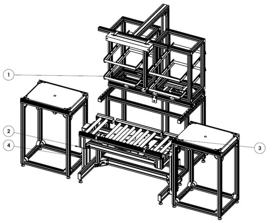
Figure 2.
Components of the self-adapting assembly workstation: 1. Modules for the storage of the assembly parts and components; 2. Extendable supports of the main roller conveyor; 3. Lateral roller conveyor; and 4. Main roller conveyor. (LE = Lateral Extension; FE = Frontal Extension; VE = Vertical Extension).
3.2. Test Cases
Two test studies have been developed to test the reliability of the anthropometric measurements acquired with the 3-D sensing device described in Section 3.1. Test 1 aimed to determine the optimal position of the 3-D sensing device testing different locations of the camera. Test 2 investigated a sample of 10 individuals, with one scan for each individual. The two tests were carried out in the Laboratory of Industrial Engineering at the University of Bologna (Italy), where the A3S is located. The prototype, as in Figure 1 and Figure 2, has limited dimensions, and the laboratory environment is characterized by a light brightness comparable with that of a traditional industrial context. These operative conditions allow us to overcome the main limitations of the Kinect cameras, as discussed in Section 1.
In the first test, the height and the inclination of the camera have been modified. Specifically, four different heights of the camera have been tested, and each height is associated with a different camera inclination for a total of 12 sub-tests (Table 1). The height of the camera varied from 1.50 to 1.70 m, while the inclination ranged from −8° to 15°. These values are selected since they allow efficient and accurate human body tracking. The distance of the 3-D sensing device from the assembly worker was fixed at 3 m. The investigated anthropometric measurements were elbow height, eye height, elbow–hand grip length, arm length, and shoulder height [27]. The results of the Test 1 are in the following table. Observed values are the measurements tracked with the 3-D sensing device. Effective values refer to the real body dimensions, and they are measured by using an anthropometer tool. Observed and effective measurements have been compared. Delta represents the absolute difference between the two measurements. The lower the value of Delta, the higher the precision of the measurement.

Table 1.
Results of Test 1.
The results of Test 1 show that positioning the camera at a height of 1.6 m with an inclination of −15° with respect to the horizontal ensures higher precision (Sub-test 8). The body dimensions of 10 individuals were measured in Test 2. The experimental setup was similar to Test 1, i.e., the distance of the 3-D sensing device from the assembly worker was fixed at 3 m, and the anthropometer was used to measure the effective values of the body parts. In particular, the investigated anthropometric measurements were elbow height, eye height, elbow–hand grip length, arm length, and shoulder height. One scan was performed for each assembly worker. Specifically, the inclination and the height of the camera in Test 2 were set as in Sub-test 8 of Test 1. The results of Test 2 are in Table 2.
Table 2.
Results of Test 2.
The percentages of the average errors in Table 2 range between 2% and 8%. Such values are acceptable for the purposes of this study. Once the optimal position of the 3-D-sensing device was determined and the effective and accurate tracking of human body parts was tested, the next step was to allow a real-time reconfiguration of the A3S by including ergonomic aspects in the assembly system logic control.
3.3. Including Ergonomics in the Logic Control of the A3S
To allow a real-time reconfiguration of the A3S prototype according to the anthropometric measurements of the human operators, an integration between the phases of logic control programming and skeleton tracking is mandatory. To do this, MATLAB software is used as a common programming environment by using the Motion Logic Programming Interface (MLPI) libraries for the A3S logic control programming and the Image Acquisition Toolbox (IAT) for the skeleton tracking. IAT is a computer vision-based tool that provides functions and blocks that enable the connection of industrial and scientific cameras, i.e., 3-D depth cameras, machine vision cameras and frame grabbers, to MATLAB and Simulink. The device used in this study is a Microsoft Kinect. It is equipped with two main sensors: one color sensor to acquire RGB images and one depth sensor to acquire skeletal data.
The acquisition of the anthropometric measurements consists of detecting the body dimensions of the operator in front of the assembly workstation. After a short initial setup for the necessary input configurations, the skeleton tracking function is launched. Specifically, the skeleton is a set of points (joints) positioned in relevant areas of the body. The relative distances between the points of the skeleton are calculated, and the anthropometric measurements of interest are extracted. The detected anthropometric measurements are transmitted to the anthropometric module of the A3S logic control, which proposes the positions that the workstation has to assume to the actuators. The outputs of the anthropometric module are the inputs for the self-adaption of the A3S (Figure 3).
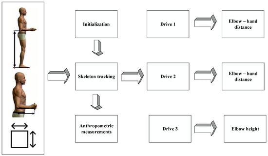
Figure 3.
Anthropometric module composition and purposes.
The programming code for the anthropometric module of the A3S consists of three sections: Drive 1, Drive 2 and Drive 3. The first section determines the frontal extension (see FE in Figure 2) of the modules (Drive 1). The ergonomic principle for the design of an ergonomic workplace suggests setting the work area and working devices within the so-called “golden zone”. The golden zone in ergonomics refers to the area between the mid-thigh and mid-chest [18,19]. Given the characteristics of A3S in Figure 1, the aim is to set the frontal extension of the module, allowing the operator to take the assembly parts according to the distance between the elbow and the hand. The extension of the module is inversely proportional to the arm length. Moreover, the closer the modules to the workpiece, the less is the distance that the worker’s hand has to cover. As a result, a shorter distance to pick up the assembly parts leads to reduced number of movements, improved ergonomic conditions, shorter time to assemble the components and higher productivity.
Drive 2 sets the lateral extension of the two modules, while Drive 3 computes the position of the third axis, which controls the height of the work surface (see LE and VE in Figure 2). ISO 14738 [29] suggests setting the height of the work surface according to the type of activity to perform. In the case of precision work, the working surface should be higher than the elbow height; in the case of low-precision work, e.g., the assembly of the centrifugal electric pump in Section 4, the height of the work surface should be equal to or lower than the elbow height. This allows the operator to work at a 90-degree angle between the arm and the forearm.
4. The Assembly of a Centrifugal Electric Pump
This section introduces the characteristics of the investigated case study and the ergonomic risk assessment for an assembly process performed at a traditional assembly workstation with a fixed layout in the first stage (Configuration #1) and at the A3S prototype in the second stage (Configuration #2) for comparison. A male operator (height 1.80 m, weight 85 kg, age 30) simulated the assembly process of a horizontal multistage centrifugal electric pump. Figure 4 and Table 3 show the sketch and the bill of materials for the reference pump.
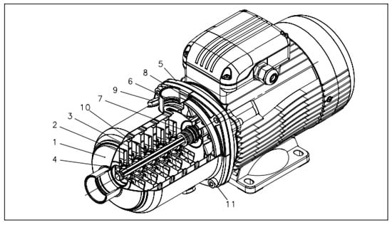
Figure 4.
Parts of the multistage horizontal centrifugal electric pump (components description is in Table 3).
Table 3.
Bill of materials for the horizontal multistage centrifugal electric pump.
This study focuses on the assembly of the pump components characterized by high weight and size, i.e., pump crankcase, rotor and seal housing disc. The remaining components are small metal parts, and their assembly is not relevant for the purposes of this study. Specifically, the reference assembly tasks consist of placing the rotor in the pump crankcase and positioning the seal housing disc on it. Figure 5 shows the crankcase, the rotor and the seal housing disc of the multistage centrifugal electric pump.
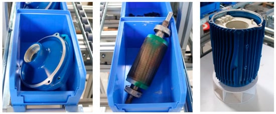
Figure 5.
Parts of the horizontal multistage centrifugal electric pump. From the left: seal housing disk, pump rotor and pump crankcase.
The assembly worker performed the technical actions in Table 4 to assemble one pump. Table 4 shows the technical actions of each arm and the time required in seconds.
Table 4.
Technical actions performed with each arm to assemble the parts in Figure 6.
The workpiece arrives from the previous assembly workstation on a table. At this stage, the crankcase is fixed on the workpiece. The assembly worker moves the component with the left hand to the main roller conveyor and takes the rotor from the box on the module. Then, the worker places this component with both hands inside the crankcase. With the right hand, the worker takes the seal housing disk and places it with both hands on the crankcase. Some pressure is required to fix the two components correctly. Finally, the right hand pushes the work table to the right, moving the workpiece towards that direction. The cycle time required to perform the introduced assembly task is 17 s. The pace of the operation depends on the takt time imposed by the production strategy. The ergonomic risk due to repetitive movements of the upper limbs has been assessed, considering the case study of an assembly worker who is required to perform the described assembly operation during an 8 h shift. A break of 30 min is included, and the net duration of the repetitive task is 450 min. The production volume considered for the ergonomic risk assessment is 1570 pieces per worker and work shift. Finally, the simulation considered the presence of seven hours during the work shift with proper recovery, as required by ISO 11228-3:2007 [45].
In Configuration #1, the main roller conveyor was set to a height of 0.95 m and the two modules that characterize the picking area were positioned as in Figure 1. The following Table 5 shows the investigated parameters for the ergonomic risk assessment of the assembly operation in Configuration #1 by using the OCcupational Repetitive Action (OCRA) method for the evaluation of risk factors in relation to repetitive movements with the upper limbs [46]. The OCRA index investigates the ratio between the number of actual technical actions necessary to perform the task and the number of reference technical actions recommended for ensuring an acceptable risk.
Table 5.
List of the OCRA parameters and indices for the assembly operation in the fixed workstation (Configuration #1).
The OCRA indices for both the right and the left arm reveal acceptable exposure to the risk of repetitive movements, i.e., the threshold limit value for the presence of high risk is 2.1. In Configuration #2, the assembly process was performed at the A3S equipped with Microsoft KinectTM. In such a configuration, the real-time control program sets the main roller conveyor height and the position of the two modules according to the operator’s anthropometric measurements. A second ergonomic risk assessment was performed. The results are in Section 5.
5. Results and Discussion
The assembly operation in Section 4 was performed at the A3S with the 3-D sensing device described in Section 3. The control program was activated, and the 3-D sensing device retrieved the anthropometric measurements of the operator at the workstation, i.e., the inputs of the control program for the smart workstation are the anthropometric measurements of the operator. A second ergonomic risk assessment with the OCRA method was performed to investigate the impact of automation and 3-D sensing on the risk of repetitive movements. Table 6 summarizes the OCRA parameters and the results of the ergonomic risk assessment.
Table 6.
List of the OCRA parameters and indices for the assembly operation at the A3S (Configuration #2).
The OCRA index for the right limb improved significantly from 1.6 (Table 5) to 1.1 (Table 6). The OCRA index for the left arm is constant and equal to 1.7.
The operator revealed that the assembly tasks at the smart assembly station required less effort and muscular fatigue compared with the fixed workstation. Specifically, the worker stated that the effort required to reach the assembly parts was reduced in the smart workstation. In addition, such a workstation improved the comfort of the back, neck and shoulders thanks to the optimal height of the work surface.
Figure 6, Figure 7 and Figure 8 show three assembly tasks performed at the fixed workstation (left) and at the A3S (right). In Figure 6, the operator takes the rotor from the module. Figure 7 shows the assembly of the rotor in the crankcase, while Figure 8 shows the positioning of the seal housing disc.
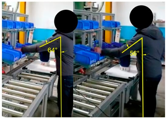
Figure 6.
Picking of the rotor from the module (left: fixed workstation; right: A3S).
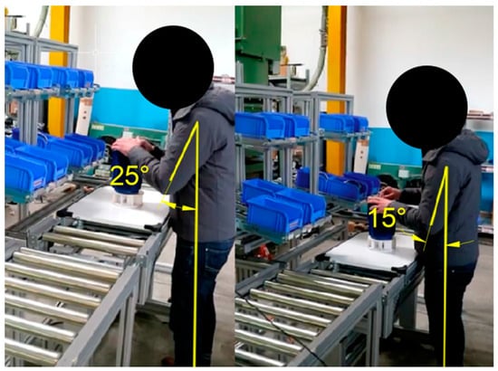
Figure 7.
Assembly of the seal housing disk (left: fixed workstation; right: A3S).
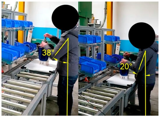
Figure 8.
Insertion of the rotor into the crankcase (left: fixed workstation; right: A3S).
Figure 6, Figure 7 and Figure 8 show also the impact of the A3S on the shoulder posture. Specifically, the shoulder flexion reduces with the adaption of the workstation to the operator’s body dimensions.
Results in Table 7 confirm that the A3S allows a significant reduction of the shoulder flexion angle. The maximum reduction is obtained when the operator inserts the rotor into the crankcase, i.e., the shoulder flexion angle in the A3S is reduced by 47%. The above-described results confirm the benefits of the A3S design and implementation towards traditional assembly layouts. From an economic perspective, flexible automation and intelligent manufacturing always require an initial investment able to reduce production costs over the system’s lifetime. In this paper, benefits are quantified from an ergonomic perspective, which is a key asset to consider in every industry, but cost and return on investment need to be addressed in the near future after the full ramp-up in the industry. Moreover, the proposed advanced assembly prototype can act as inspiration for many industries producing small- or medium-sized products looking for flexibility, adaptivity and ergonomic improvements. In fact, while the literature is rich in studies proposing mathematical methods or algorithms to design intelligent production systems, papers proposing full-scale prototypes are rare and expected.
Table 7.
Variation of the shoulder flexion angle using the fixed workstation and the A3S.
6. Conclusions and Future Research
The traditional anthropometric design is based on three major principles: design for extreme individual, i.e., designing for the maximum population, commonly referred to as the 95th percentile male, or designing for the minimum population value, commonly referred to as the 5th percentile female; design for an adjustable range, which considers both the 5th percentile female and 95th percentile male in order to accommodate 90% of the population; and design for the average, i.e., accommodating 50% of the user population [47]. Thus, the design of the work and living environment is based on statistical data on the body dimensions of the intended user population, aiming to accommodate most of the user population or to exclude a few [48]. However, the design of products, equipment, services or workplaces following the 5th and 95th percentile criteria is unable to provide appropriate support for achieving the objective of design inclusiveness [49].
This paper introduced an innovative approach to the ergonomic design of smart manufacturing systems. The aim was to adapt an assembly workstation to the operator dimensions, improving the ergonomics of the workstation and workers’ health and safety. An adaptive automation assembly system (A3S) prototype equipped with a 3-D sensing technology for real-time adjustment was introduced. The system acquires the anthropometric measurements of the human operators by means of the 3-D sensing device and arranges the mobile elements of the assembly workstation accordingly. Specifically, the workstation adapts its layout to the body dimensions of the operator, reducing the risks of biomechanical overload and awkward postures.
The case study of an assembly process of a centrifugal electric pump was described to validate the proposed approach. The assembly operation was simulated at a traditional fixed workstation and at the A3S. The shoulder flexion angle during the assembly tasks at the A3S reduced between 18% and 47%. The ergonomic risk assessment confirmed the improvement of the ergonomic conditions and the ergonomic benefits of such a system. Furthermore, the proposed approach improves the traditional approaches for the design of assembly workstations. Among the limitations of this study, it is worth noting that the proposed advanced assembly prototype is suitable for the manufacturing of small- to medium-sized products. Hence, for large-sized products, further assembly layouts need to be designed.
Future development of this study will include analyses of the impact of the A3S on the productivity of the assembly operator.
Author Contributions
Conceptualization, M.B., L.B., C.M. and F.G.G.; methodology, L.B. and F.G.G.; software, L.B. and F.G.G.; investigation, M.B., L.B. and F.G.G.; writing—original draft preparation, L.B. and F.G.G.; writing—review and editing, M.B. and C.M.; supervision, C.M. All authors have read and agreed to the published version of the manuscript.
Funding
This research received no external funding.
Data Availability Statement
Data are contained within the article.
Conflicts of Interest
The authors declare no conflict of interest.
References
- Carayon, P.; Smith, M.J. Work organization and ergonomics. Appl. Ergon. 2000, 31, 649–662. [Google Scholar] [CrossRef]
- Aarås, A.; Horgen, G.M.; Bjørset, H.H.; Ro, O.M.; Walsøe, H. Musculoskeletal, visual and psychosocial stress in VDU operators before and after multidisciplinary ergonomic interventions. A 6 years prospective study—Part II. Appl. Ergon. 2001, 32, 559–571. [Google Scholar] [CrossRef] [PubMed]
- Ketola, R.; Toivonen, R.; Häkkänen, M.; Luukkonen, R.; Takala, E.P.; Viikari-Juntura, E.; Expert Group in Ergonomics. Effects of ergonomic intervention in work with video display units. Scand. J. Work Environ. Health 2002, 28, 18–24. [Google Scholar] [CrossRef]
- Robertson, M.M.; Huang, Y.H.; O’Neill, M.J.; Schleifer, L.M. Flexible workspace design and ergonomics training: Impacts on the psychosocial work environment, musculoskeletal health, and work effectiveness among knowledge workers. Appl. Ergon. 2008, 39, 482–494. [Google Scholar] [CrossRef] [PubMed]
- Das, B.; Sengupta, A.K. Industrial workstation design: A systematic ergonomics approach. Appl. Ergon. 1996, 27, 157–163. [Google Scholar] [CrossRef] [PubMed]
- Scott, G.B.; Lambe, N.R. Working practices in a perchery system, using the OVAKO Working posture Analysing System (OWAS). Appl. Ergon. 1996, 27, 281–284. [Google Scholar] [CrossRef] [PubMed]
- Kadefors, R.; Forsman, M. Ergonomic evaluation of complex work: A participative approach employing video–computer interaction, exemplified in a study of order picking. Int. J. Ind. Ergon. 2000, 25, 435–445. [Google Scholar] [CrossRef]
- Martin, C.C.; Burkert, D.C.; Choi, K.R.; Wieczorek, N.B.; McGregor, P.M.; Herrmann, R.A.; Beling, P.A. A real-time ergonomic monitoring system using the Microsoft Kinect. In Proceedings of the Systems and Information Design Symposium (SIEDS), 2012 IEEE, Charlottesville, VA, USA, 27 April 2012; pp. 50–55. [Google Scholar]
- Han, J.; Shao, L.; Xu, D.; Shotton, J. Enhanced computer vision with microsoft kinect sensor: A review. IEEE Trans. Cybern. 2013, 43, 1318–1334. [Google Scholar]
- Zhang, Z. Microsoft kinect sensor and its effect. IEEE Multimed. 2012, 19, 4–10. [Google Scholar] [CrossRef]
- Bonnechère, B.; Jansen, B.; Salvia, P.; Bouzahouene, H.; Sholukha, V.; Cornelis, J.; Rooze, M.; Van Sint Jan, S. Determination of the precision and accuracy of morphological measurements using the KinectTM sensor: Comparison with standard stereophotogrammetry. Ergonomics 2014, 57, 622–631. [Google Scholar] [CrossRef]
- Xu, X.; McGorry, R.W. The validity of the first and second generation Microsoft KinectTM for identifying joint center locations during static postures. Appl. Ergon. 2015, 49, 47–54. [Google Scholar] [CrossRef] [PubMed]
- Dutta, T. Evaluation of the KinectTM sensor for 3-D kinematic measurement in the workplace. Appl. Ergon. 2012, 43, 645–649. [Google Scholar] [CrossRef] [PubMed]
- Bortolini, M.; Faccio, M.; Galizia, F.G.; Gamberi, M.; Pilati, F. Design, engineering and testing of an innovative adaptive automation assembly system. Assem. Autom. 2020, 40, 531–540. [Google Scholar] [CrossRef]
- Dul, J.; Neumann, W.P. Ergonomics contributions to company strategies. Appl. Ergon. 2009, 40, 745–752. [Google Scholar] [CrossRef]
- Falck, A.C.; Rosenqvist, M. Assembly failures and action cost in relation to complexity level and assembly ergonomics in manual assembly (part 2). Int. J. Ind. Ergon. 2014, 44, 455–459. [Google Scholar] [CrossRef]
- Finnsgard, C.; Wanstrom, C.; Medbo, L.; Neumann, W.P. Impact of materials exposure on assembly workstation performance. Int. J. Prod. Res. 2011, 49, 7253–7274. [Google Scholar] [CrossRef]
- Botti, L.; Mora, C.; Regattieri, A. Application of a mathematical model for ergonomics in lean manufacturing. Data Brief 2017, 14, 360–365. [Google Scholar] [CrossRef]
- Botti, L.; Mora, C.; Regattieri, A. Integrating ergonomics and lean manufacturing principles in a hybrid assembly line. Comput. Ind. Eng. 2017, 111, 481–491. [Google Scholar] [CrossRef]
- Kushwaha, D.K.; Kane, P.V. Ergonomic assessment and workstation design of shipping crane cabin in steel industry. Int. J. Ind. Ergon. 2016, 52, 29–39. [Google Scholar] [CrossRef]
- ISO 45001:2018; Occupational Health and Safety Management Systems—Requirements with Guidance for Use. International Standard Organization (ISO): Geneva, Switzerland, 2018.
- Šolc, M.; Blaško, P.; Girmanová, L.; Kliment, J. The Development Trend of the Occupational Health and Safety in the Context of ISO 45001:2018. Standards 2022, 2, 294–305. [Google Scholar] [CrossRef]
- Kapp, E. PW 2499 Using Iso 45001 To Improve Safety & Heath in the Global Supply Chain. Inj. Prev. 2018, 24, A242–A243. [Google Scholar] [CrossRef]
- ISO 6385-2016; Ergonomics Principles in the Design of Work Systems. International Standard Organization (ISO): Geneva, Switzerland, 2016.
- ISO 9241-210:2010; Ergonomics of Human-System Interaction—Part 210: Human-Centred Design for Interactive Systems. International Standard Organization (ISO): Geneva, Switzerland, 2010.
- EN 614-2:2000 + A1:2008; Safety of machinery—Ergonomic design principles—Part 2: Interactions between the design of machinery and work tasks. CEN: Oak Brook, IL, USA, 2008.
- ISO 7250-1:2017; Basic Human Body Measurements for Technological Design. Part 1: Body Measurement Definitions and Landmarks. International Standard Organization (ISO): Geneva, Switzerland, 2017.
- ISO/TR 7250-2:2010; Basic human body measurements for technological design. Part 2: Statistical summaries of body measurements from national populations. International Standard Organization (ISO): Geneva, Switzerland, 2010.
- ISO 14738; Safety of machinery. Anthropometric requirements for the design of workstations at machinery. International Standard Organization (ISO): Geneva, Switzerland, 2002.
- Caruso, L.; Russo, R.; Savino, S. Microsoft Kinect V2 vision system in a manufacturing application. Robot. Comput.-Integr. Manuf. 2017, 48, 174–181. [Google Scholar] [CrossRef]
- Manghisi, V.M.; Uva, A.E.; Fiorentino, M.; Bevilacqua, V.; Trotta, G.F.; Monno, G. Real-time RULA assessment using Kinect v2 sensor. Appl. Ergon. 2017, 65, 481–491. [Google Scholar] [CrossRef] [PubMed]
- Plantard, P.; Shum, H.P.H.; Le Pierres, A.S.; Multon, F. Validation of an ergonomic assessment method using Kinect data in real workplace conditions. Appl. Ergon. 2017, 65, 562–569. [Google Scholar] [CrossRef]
- Jun, C.; Lee, J.Y.; Kim, B.H.; Do Noh, S. Automatized modeling of a human engineering simulation using Kinect. Robot. Comput.-Integr. Manuf. 2019, 55, 259–264. [Google Scholar] [CrossRef]
- Demirel, H.O.; Duffy, V.G. Applications of Digital Human Modeling in Industry. In Digital Human Modeling; Springer: Berlin/Heidelberg, Germany, 2007; pp. 824–832. [Google Scholar]
- Botti, L.; Gamberi, M.; Manzini, R.; Mora, C.; Regattieri, A. A bi-objective optimization model for work activity scheduling of workers exposed to ergonomic risk. In Proceedings of the Summer School Francesco Turco 2014, Senigallia, Italy, 9–12 September 2014. [Google Scholar]
- Napoli, A.; Glass, S.; Ward, C.; Tucker, C.; Obeid, I. Performance analysis of a generalized motion capture system using microsoft kinect 2.0. Biomed. Signal Process. Control. 2017, 38, 265–280. [Google Scholar] [CrossRef]
- Nanthavanij, S. Body height-workstation settings matrix: A practical tool for ergonomic VDT workstation adjustment. Int. J. Ind. Ergon. 1996, 18, 215–219. [Google Scholar] [CrossRef]
- Nanthavanij, S. An ergonomic assessment of fixed-height, partially adjustable, and fully adjustable VDT workstations by IntelAd. Comput. Ind. Eng. 1994, 27, 361–364. [Google Scholar] [CrossRef]
- Zha, X.F.; Lim, S.Y.E. Intelligent design and planning of manual assembly workstations: A neuro-fuzzy approach. Comput. Ind. Eng. 2003, 44, 611–632. [Google Scholar] [CrossRef]
- Lin, R.T.; Chan, C.C. Effectiveness of workstation design on reducing musculoskeletal risk factors and symptoms among semiconductor fabrication room workers. Int. J. Ind. Ergon. 2007, 37, 35–42. [Google Scholar] [CrossRef]
- Hernandez-Arellano, J.L.; Serratos-Perez, J.N.; de la Torre, A.; Maldonado-Macias, A.A.; Garcia-Alcaraz, J.L. Design Proposal of an Adjustable Workstation for Very Short and Very Tall People. Procedia Manuf. 2015, 3, 5699–5706. [Google Scholar] [CrossRef][Green Version]
- Jung, H.S. A prototype of an adjustable table and an adjustable chair for schools. Int. J. Ind. Ergon. 2005, 35, 955–969. [Google Scholar] [CrossRef]
- Delleman, N.J.; Dul, J. Sewing machine operation: Workstation adjustment, working posture, and workers’ perceptions. Int. J. Ind. Ergon. 2002, 30, 341–353. [Google Scholar] [CrossRef]
- Brkić, V.S.; Klarin, M.M.; Brkić, A.D. Ergonomic design of crane cabin interior: The path to improved safety. Saf. Sci. 2015, 73, 43–51. [Google Scholar] [CrossRef]
- ISO 11228-3:2007; Ergonomics—Manual Handling—Part 3: Handling of Low Loads at High Frequency. International Standard Organization (ISO): Geneva, Switzerland, 2007.
- Colombini, D.; Occhipinti, E. Application of concise exposure index (OCRA) to tasks involving repetitive movements of the upper limbs in various industrial settings: Preliminary experience and validation. Occup. Health Ind. Med. 1997, 2, 76. [Google Scholar]
- Taifa, I.W.; Desai, D.A. Anthropometric measurements for ergonomic design of students’ furniture in India. Eng. Sci. Technol. Int. J. 2017, 20, 232–239. [Google Scholar] [CrossRef]
- Konz, S. Workstation organization and design. Int. J. Ind. Ergon. 1990, 6, 175–193. [Google Scholar] [CrossRef]
- Hussain, A.; Case, K.; Marshall, R.; Summerskill, S. Joint mobility and inclusive design challenges. Int. J. Ind. Ergon. 2016, 53, 67–79. [Google Scholar] [CrossRef]


Disclaimer/Publisher’s Note: The statements, opinions and data contained in all publications are solely those of the individual author(s) and contributor(s) and not of MDPI and/or the editor(s). MDPI and/or the editor(s) disclaim responsibility for any injury to people or property resulting from any ideas, methods, instructions or products referred to in the content. |
© 2023 by the authors. Licensee MDPI, Basel, Switzerland. This article is an open access article distributed under the terms and conditions of the Creative Commons Attribution (CC BY) license (https://creativecommons.org/licenses/by/4.0/).