Communication

Geometric Attitude Fault-Tolerant Control of Quadrotor Unmanned Aerial Vehicles with Adaptive Extended State Observers

Key Laboratory of Autonomous Systems and Networked Control, Ministry of Education, Guangdong Engineering Technology Research Center of Unmanned Aerial Vehicle Systems, South China University of Technology, Guangzhou 510640, China
*
Author to whom correspondence should be addressed.
Machines 2024, 12(1), 47; https://doi.org/10.3390/machines12010047
Submission received: 27 November 2023 / Revised: 6 January 2024 / Accepted: 7 January 2024 / Published: 10 January 2024
(This article belongs to the Special Issue Advanced Control and Path Planning of Unmanned Aerial Vehicles (UAVs))

Abstract

:
This paper is concerned with the attitude tracking problem of quadrotor unmanned aerial vehicles (UAVs) with respect to endogenous uncertainties, exogenous disturbances and actuator failures. Two different control methods are proposed to solve this problem. First, an adaptive extended state observer (AESO)-based control framework is devised to tackle the difficulties caused by model uncertainties and external disturbances. A fault-tolerant control method is proposed to cope with the occurrence of actuator failure, which is modeled as a constant loss of effectiveness. Another method employs AESOs to compensate for lumped disturbances, which include endogenous uncertainties, exogenous disturbances and actuator failures. Then, the error can exponentially converge to a bounded set. Finally, simulations are performed to ensure the feasibility of the designed technique.

1. Introduction

In recent years, unmanned aerial vehicles (UAVs) have attracted a great deal of attention due to their wide range of applications in various military, civilian and medical areas. The control problems of UAVs, such as complex flight maneuvers, large-angle flips, stabilization and tracking, have been widely studied by many researchers [1,2].
In many practical systems, disturbances and uncertainties [3,4,5,6,7,8,9,10,11,12,13] exist widely in the form of unmodeled dynamics, inertia matrix uncertainties or exogenous disturbances. Extended state observers (ESOs), which were first presented by Han [5,6,7], are powerful and efficient in estimating and counteracting lumped disturbances, which include all the endogenous uncertainties and exogenous disturbances. ESOs can be classified into two main types: nonlinear ESOs (NESOs) [8] and linear ESOs (LESOs) [9,10]. NESOs have a good estimation capability for nonlinear forms and strong robustness. An NESO [8] was employed to address the uncertainty problem of the MIMO system, but it is hard to satisfy the assumption conditions in real systems and its complex nonlinear structures and the number of parameters that need to be tuned are a problem to resolve. To reduce the number of parameters to be tuned, an LESO [9] was presented to solve the SISO uncertain system control problem by employing linear feedback instead of nonlinear feedback. LESOs have the ability to tune parameters simply. However, the design flexibility is reduced for complicated systems, and an LESO needs a high gain which may lead to a peaking phenomenon. Then, an adaptive ESO (AESO) [11] was proposed for its better estimation capabilities, simplicity of parameter tuning and design flexibility. AESOs have a linear form with an adaptive time-varying gain. Ref. [12] proposed an AESO to cope with the uncertainties both in the plant and in the sensors. Through comparison with the ESO, it can be found that the AESO possesses better control performance. Paper [13] devised an AESO-based nonsingular terminal sliding mode control (NTSMC) scheme to compensate for the unknown disturbances and parameter uncertainties.
Additionally, another key fact that may result in system performance degradation or instability is actuator faults, which are usually modeled as a constant partial loss of effectiveness (LOE). Then, the fault-tolerant control (FTC) scheme [14,15,16,17,18,19,20,21,22,23,24,25] was designed to facilitate the maintenance of system stability. An adaptive FTC method [14] was developed for nonlinear systems with actuator failures. A finite-time tracking controller [15] was designed against inertia uncertainties and external disturbances. In [16], an FTC law using online control allocation was proposed to cope with the attitude control problem with external disturbances, unknown inertia and actuator LOE. Remus C. Avram et al. [17] developed a fault detection, isolation and accommodation method for quadrotor actuator faults. Then, in [18], a fault-tolerant altitude and attitude tracking approach was proposed to address the actuator fault problem of UAVs without a fault diagnosis mechanism. A robust, adaptive FTC law [19] was developed to deal with multiple actuator faults which occur in altitude and attitude systems. A second-order fault-tolerant sliding control scheme [20] was presented to deal with system uncertainties, exogenous disturbances and reaction wheel faults of spacecraft. A fixed-time FTC scheme [21] was presented so that the current state converges to a given value in a fixed time, which can be decided by the user. Simultaneous actuator faults of UAVs were considered in [22]. In [23], actuator faults were modeled as a constant partial LOE and a fast terminal sliding mode controller was used to speed up the convergence rate. A fault detection, isolation and accommodation strategy [24] was devised to handle actuator faults and parameter uncertainties of fixed-wing UAVs. An FTC method [25] for UAVs was developed to effectively handle time-varying faults. However, the above research did not consider the possible ambiguity or singularity of quaternion or Euler-based UAV attitude representation, which can be effectively avoided by using geometric representation [2,26,27,28].
Inspired by the preceding discussion, this paper introduces two different control strategies for UAVs subject to system uncertainties and exogenous perturbations, as well as actuator faults, respectively. The main contributions can be outlined as follows:
(1)
This paper devises two different control algorithms, including an AESO-based geometric fault-tolerant control (AESOGFTC) method (passive FTC method) and an AESO-based attitude control method (active FTC method), and they both ensure that the closed-loop signals can exponentially converge to a bounded set.
(2)
In both approaches, the AESO-based control framework, without known upper bounds of the lumped disturbance, has a few parameters which need to be tuned; this makes the structure of the proposed control method more simple. In the active FTC method, while actuator failure, inertia matrix uncertainty and external perturbations occur, the AESO-based attitude control method actively estimates and compensates with an AESO. In the passive FTC method, inertia matrix uncertainty and external perturbation are regarded as the lumped disturbances that can be dealt with by the AESO.
(3)
In the passive FTC method, an FTC framework is proposed to address the attitude actuator failure problem by a constant partial LOE. As a result of the actuator failures that occur in the attitude subsystem, the model proposed in [18] does not apply to this article. Then, an improved method is developed by using the generalized inverse matrix.
(4)
By introducing the novel control laws, the actuator failures, inertia matrix uncertainty and external perturbations are simultaneously addressed.

2. Problem Statement and Preliminaries

Notation: · ^ : R 3 so ( 3 ) is t h e h a t m a p with a ^ b = a × b for a , b R 3 , whose inverse is t h e v e e m a p : so ( 3 ) R 3 . I n is the identity matrix with appropriate dimensions. The symbols · , tr ( · ) and λ ( · ) are the 2-norm, the trace and the eigenvalue of a matrix, respectively. The rotation matrix R S O ( 3 ) transforms a vector from the body coordinate system to the inertial coordinate system with the special orthogonal group S O ( 3 ) = { R R 3 × 3 | det R = 1 , R T R = I 3 } .

2.1. A Model of UAVs

Consider a second-order system of UAVs as
J w ˙ = w × J w + u + d 0 , R ˙ = R w ^ ,
where J = J + Δ J R 3 × 3 is the body inertia matrix with the diagonal inertia matrix J and the uncertain parts Δ J ; w , u R 3 are the body angular velocity and the control moment, respectively. The vector d 0 R 3 represents disturbances which include modeling errors and system noises. The control objective is to devise a controller that makes the output of the system (1) track a given signal.
For a given signal ( R d , w d ) and the current state ( R , w ) , according to [28], define the error dynamics of Ψ , e R and e w as
Ψ = 1 2 tr ( I 3 R d T R ) , e R = 1 2 ( R d T R R T R d ) , e w = w R T R d w d ,
whose derivatives satisfy
Ψ ˙ = e R · e w , e ˙ R = E ( R , R d ) e w , e ˙ w = J 1 ( w × J w + u + d ) α ,
where d is the lumped disturbance which is given in the next section. Ψ < δ < 2 with a positive constant δ , then Ψ b 1 e R 2 with b 1 = 1 2 δ . e R 2     2 Ψ , E ( R , R d ) = 1 2 tr ( R T R d ) I R T R d , α = w ^ R T R d w d + R T R d w ˙ d is the angular acceleration caused by the attitude command. Furthermore, E ( R , R d ) 3 2 .

2.2. Design and Stability Analysis of the AESO

For the following nonlinear system
X ˙ = f ( X ) + D + B U ,
where X , f ( X ) , B and U are the system state, known nonlinear function, known control gain and system input, respectively, the external disturbance D is partially or totally unknown but differentiable, and suppose that D and its derivative D ˙ are bounded with the unknown upper bound D M .
Then, for system (4), define X 1 = X and X 2 = D , and design the following AESO [11]
X ¯ ˙ 1 = f ( X ) + B U + X ¯ 2 + L 1 ( t ) ( X 1 X ¯ 1 ) , X ¯ ˙ 2 = L 2 ( t ) ( X 1 X ¯ 1 )
with the observation value X ¯ i and the time-varying gain L i ( t ) for i = 1 , 2 . Take the observation error Z i = X i X ¯ i . Then, the error system can be described as
Z ˙ 1 Z ˙ 2 = A ( t ) Z 1 Z 2 + b D ˙ ,
where Z = [ Z 1 , Z 2 ] T , A ( t ) = L 1 ( t ) 1 L 2 ( t ) 0 and b = 0 1 . According to [11,29], we transform system (6) into phase-variable form:
ζ ˙ = A c ( t ) ζ + b c D ˙ ,
where ζ is the state of system (7), A c ( t ) = 0 1 a 1 ( t ) a 2 ( t ) and b c = 0 1 . Here, let a i ( t ) be smooth (it has a continuous second-order derivative) and bounded.
L 1 ( t ) = a 2 ( t ) , L 2 ( t ) = a ˙ 2 ( t ) + a 1 ( t ) .
L i ( t ) can be expressed by a i ( t ) and its derivative. Accordingly, we can design a i ( t ) to prove system (7)’s stability, and moreover prove the stability of the AESO.
Next, consider the homogeneous form of (7) as follows
ζ ˙ = A c ( t ) ζ .
Lemma 1
([11]). For system (6), transform (6) into (7) with a transformation ζ = T ( t ) Z with the transformation matrix T ( t ) . If the two conditions hold:
(i) The PD-spectrum Υ of (9) satisfies Theorem 2.8 ([30]) and is smooth and bounded;
(ii) The disturbance item b D ˙ in (6) satisfies b D ˙     D M < h 3 h 5 h 1 h 2 θ μ for t 0 , Z { Z R 2 | Z   < μ } , and positive constants h 1 , h 2 , h 3 , h 5 , θ with 0 < θ < 1 .
Then, for all Z ( t 0 ) < h 1 h 2 μ and some finite t 1 , the solution of (6) satisfies
Z ( t ) ρ e r ( t t 0 ) Z ( t 0 ) , t 0 t t 0 + t 1 Z ( t ) Z M , t t 0 + t 1
where ρ = h 2 / h 1 , r = ( 1 θ ) h 3 2 h 2 , Z M = h 5 h 3 h 2 h 1 D M θ . Furthermore, Z 2 ( t ) Z M 2 Z 1 2 .
Remark 1.
From the definition in work [30], Υ = { p k ( t ) } k = 1 n is a PD-spectrum (parallel D-spectrum) for the scalar polynomial differential operator (SPDO) D a if p k ( t ) are PD-eigenvalues for D a and { y k ( t ) = exp ( p k ( t ) d t ) } k = 1 n comprises a fundamental set of solutions to D a ( y ) = 0 with D a = A n + a n ( t ) A n 1 + + a 2 ( t ) A + a 1 ( t ) and A = d d t . For a detailed description, please see Definition 2.1 in work [30].
Remark 2.
From Lemma 1, it is easy to obtain Z 2     Z M for t t 0 + t 1 , which implies that the observation error is directly related to the upper bound of the total disturbance. For an accurate value of the upper bound, we can obtain an accurate observation error.

3. Geometric Fault-Tolerant Tracking Control with AESOs

In this part, two different methods, which include the AESOGFTC method and the AESO-based geometric control method, are proposed to address the geometric attitude tracking control problem of UAVs subject to endogenous uncertainties, exogenous disturbances and multiplicative and additive faults.

3.1. Method I: AESO-Based Fault-Tolerant Control

In this method, an AESOGFTC law for (1) was devised, where the lumped disturbances and actuator faults are handled separately. Firstly, define the disturbance and unknown dynamic d 0 R 3 ; then, (1) can be given by
( J + Δ J ) w ˙ = w × ( J + Δ J ) w + u + d 0 .
( J + Δ J ) 1 = J 1 + J 1 Δ J ( I 3 + J 1 Δ J ) 1 J 1 = J 1 + δ J can be obtained according to [31] with δ J = J 1 Δ J ( I 3 + J 1 Δ J ) 1 J 1 . Define d 1 d 0 w × Δ J w + J δ J ( w × ( J + Δ J ) w + u + d 0 ) . System (10) can be transformed into
w ˙ = J 1 ( w × J w + u ) + J 1 d 1 .
This paper considers the effect of actuator faults caused by the rotors, so, for j = 1 , , 4 , the actuator fault model [18] can be written as
Ω j = ϵ j Ω j ,
where Ω j and Ω j are the actual and commanded rotor angular velocity, respectively. ϵ j ( ϵ ¯ , 1 ] is unknown but ϵ ¯ is a known lower bound. Then, for i = 1 , , 3 , the relationship between u i and Ω j is
u i = 1 β j ( t t j ) ϑ j k sgn ( Ω j ) Ω j 2
with the torque parameter k and the signum function sgn ( · ) . Suppose β j ( · ) is a step function; that is, for j = 1 , , 4 and the unknown fault occurrence time t j ,
β j ( t t j ) = 0 , t < t j , 1 , t t j .
Additionally, define the parameter ϑ j = 1 ϵ j 2 , where ϑ j ( 0 , ϑ ¯ ) is unknown with ϑ ¯ 1 ϵ ¯ 2 < 1 . Then, the control moment is rewritten as
u = M ( I 4 j = 1 4 β j ( t t j ) ϑ j Λ j ) Ω ¯ + a ( t ) ,
where u = [ u 1 , u 2 , u 3 ] T , Ω ¯ [ Ω 1 2 , Ω 2 2 , Ω 3 2 , Ω 4 2 ] T , the bias torque a ( t ) R 3 × 1 is bounded and I 4 is the 4 × 4 identity matrix. M R 3 × 4 is the mapping matrix between torques and rotor angular velocities. Λ j delineates the location of an actuator fault with Λ 1 = diag { 1 , 0 , 0 , 0 } , Λ 2 = diag { 0 , 1 , 0 , 0 } , Λ 3 = diag { 0 , 0 , 1 , 0 } , Λ 4 = diag { 0 , 0 , 0 , 1 } . Moreover,
w ˙ = J 1 M ( I 4 j = 1 4 β j ( t t j ) ϑ j Λ j ) Ω ¯ + J 1 d J 1 w × J w
with the lumped disturbance d = d 1 + a ( t ) .
Remark 3.
In real flight, due to the harsh working environment, unstable electronic devices, the aging of and damage to actuators, the failure of sensing devices, insufficient battery power, motor failure and other reasons, attitude control failure or abnormal situations often occur. There exists a difference between the faulty measured value and the actual measured value (i.e., additive faults).
Considering the extended state X ¯ 2 of the AESO, we can obtain the estimation value d ¯ of the lumped disturbance d.
Theorem 1.
For system (1) and positive constants k R , k w , k ϑ , υ R , define the system input Ω ¯ and the fault parameter update law of the estimate ϑ ^ :
Ω ¯ = ( I 4 j = 1 4 β j ( t t j ) ϑ ^ j Λ j ) 1 pinv ( M ) ( k R e R k w e w + w × J w + J α J d ¯ ) , ϑ ^ ˙ = P ( Θ ) , Θ = k ϑ ( j = 1 4 ( β j ( t t j ) Λ j ) Ω ¯ ) ( M T ( e w + c e R ) ) k ϑ υ ϑ ^ P ( Θ ) = 0 , i f Θ > 0 a n d ϑ ^ ϑ ¯ o r i f Θ < 0 a n d ϑ ^ 0 , Θ , o t h e r w i s e .
where the positive value c satisfies
c < min { λ m k R λ M , 2 b 1 k R λ M , K }
with K = ( 3 / 2 λ M k R + k w 2 / 4 + k w / 2 1 / 4 K 1 ) / ( 3 / 2 λ M ) , K 1 = ( 3 2 λ M k R 1 2 k w + 1 4 1 4 k w 2 ) 2 + 3 2 λ M ( k R k w + 1 2 k R ) . λ M and λ m are the maximum and minimum eigenvalues of J. pinv ( M ) is a generalized inverse matrix, and the mathematical operator ∘ is the Hadamard product. Then, the error exponentially converges to a bounded set.
Proof of Theorem 1.
Choose the Lyapunov function
V = 1 2 e w · J e w + k R Ψ + c J e w · e R + 1 2 k ϑ ϑ ˜ T ϑ ˜ ,
where the estimation error ϑ ˜ = ϑ ^ ϑ , ϑ ˜ = [ ϑ ˜ 1 , ϑ ˜ 2 , ϑ ˜ 3 , ϑ ˜ 4 ] T and c can be designed later. Since e R 2     2 Ψ , then
x 1 T W 11 x 1 V x 1 T W 12 x 1
with x 1 = [ e R , e w , ϑ ˜ F ] T R 3 , and
W 11 = 1 2 k R 1 2 c λ M 0 1 2 c λ M 1 2 λ m 0 0 0 1 2 k ϑ , W 12 = b 1 k R 1 2 c λ M 0 1 2 c λ M 1 2 λ M 0 0 0 1 2 k ϑ .
Substituting (16) in (15) and defining d ˜ = d d ¯ , one has
J e ˙ w = ( w × J w + M ( I 4 j = 1 4 β j ( t t j ) ϑ j Λ j ) Ω ¯ + d ) J α = k R e R k w e w + d ˜ + M j = 1 4 ( β j ( t t j ) ϑ ˜ j Λ j ) Ω ¯ .
Combined with (3), (16), (18) and ϑ ^ ˙ = ϑ ˜ ˙ , the derivative of V is
V ˙ = e w · J e ˙ w + k R e R · e w + c J e ˙ w · e R + c J e w · e ˙ R + 1 k ϑ ϑ ˜ T ϑ ^ ˙ = k w e w 2 c k R e R 2 c k w e w · e R + c J e w · E e w + d ˜ · ( e w + c e R ) υ ϑ ^ F 2 .
According to the results of Lemma 1 and the Young inequality, we can get
d ˜ · ( e w + c e R ) B ( e w + c e R ) B 2 + 1 2 e w 2 + c 2 2 e R 2 ,
where the upper bound of the observation error is B = [ B 1 , B 2 , B 3 ] T , in which B 1 , B 2 , B 3 can be designed in the roll–pitch–yaw dynamic, respectively. Moreover,
V ˙ x 1 T W 2 x 1 + B 2
with W 2 = c k R c 2 / 2 c / 2 k w 0 c / 2 k w k w 3 c / 2 λ M 1 / 2 0 0 0 υ . Since the positive constant c satisfies (17), this ensures that the matrices W 11 , W 12 , W 2 are positive definite. Then,
V ˙ λ m ( W 2 ) λ M ( W 12 ) V + B 2 ,
which means that V ˙ 0 if V > λ M ( W 12 ) λ m ( W 2 ) B 2 κ 1 . Define a subset of V as S ι = { ( R , w ) S O ( 3 ) × R 3 | V ι } . When the constant ι satisfies ι < δ b 1 λ m ( W 11 ) κ 2 , S ι D × R 3 . This means that x 1 2 < δ b ; moreover, Ψ b 1 e R 2     b 1 x 1 2 < ψ . When κ 1 < ι < κ 2 , the positive invariant set S ι becomes smaller if ι = κ 1 . To prove the existence of S ι , κ 1 = λ M ( W 12 ) λ m ( W 2 ) B 2 < ψ b 1 λ m ( W 11 ) = κ 2 holds. Finally, from Theorem 5.1 in [32], while the initial condition satisfies V ( 0 ) < κ 2 , its solution exponentially converges to the bounded set S ι { x 1 2 λ M ( W 12 ) λ m ( W 11 ) λ m ( W 2 ) B 2 } .
Remark 4.
From the above proof, the size of bounded set S ι depends on the value of B and moreover, it depends on the value of upper bound of the lumped disturbance.

3.2. Method II: AESO-Based Geometric Control Method

In this method, we consider actuator failures, which include multiplicative and additive failures. Define the input of actuators as
u = u r + Δ u ,
where u r is the computed input and Δ u is the actuator faults, with
Δ u = ( j = 1 4 β j ( t t j ) ϑ j Λ j ) pinv ( M ) u r + a ( t ) .
Then, (1) can be given by
w ˙ = J 1 w × J w + J 1 u r + J 1 d
with the lumped disturbance d w × Δ J w J δ J w × ( J + Δ J ) w + J ( J 1 + δ J ) ( Δ u + d 0 ) + J δ J u r .
Theorem 2.
For system (25) and positive constants k R , k w R , design the control torque
u r = k R e R k w e w + w × J w + J α d ¯ ,
where d ¯ is the observation value of d. The constant c satisfies
c < min { λ m k R λ M , 2 b 1 k R λ M , K }
with K = ( 3 / 2 λ M k R + k w 2 / 4 + k w / 2 1 / 4 K 1 ) / ( 3 / 2 λ M ) , K 1 = ( 3 2 λ M k R 1 2 k w + 1 4 1 4 k w 2 ) 2 + 3 2 λ M ( k R k w + 1 2 k R ) . Then, the tracking error exponentially converges to a bounded set.
Proof of Theorem 2.
Select a Lyapunov function
V = 1 2 e w · J e w + k R Ψ ( R , R d ) + c J e w · e R ,
where c can be designed as in (27). The next proof is similar to that of Theorem 1. □
Remark 5.
In this part, we devised two FTC methods which include active FTC (the AESO-based geometric control method) and passive FTC (the AESO-based FTC method); they could both achieve the control objectives of this article, respectively. The conclusions of the two Theorems seemed to be similar, both methods contained an AESO and most of the parameters were chosen to be the same, but the objects to be observed were different.

4. Simulations

In this part, the control performance of the proposed methods is tested on Simulink to explain the feasibility of designed controllers. The proposed AESO-based FTC method (Method I), the proposed AESO-based geometric control method (Method II) and the geometric FTC method ([28]) are compared under the same system parameters. The detailed parameters of system and the controller were chosen as
Δ J = 0 5.156 × 10 6 2.364 × 10 5 5.156 × 10 6 0 1.26 × 10 5 2.364 × 10 5 1.26 × 10 5 0 ,
J = diag { 0.010703 , 0.010340 , 0.017886 } , c = 0.1 , k ϑ = 0.001 , υ = 1 ,
k R = 5 , k w = 5.2 , d 0 = 1 14 [ 4 sin ( 3 14 t ) , 3 cos ( 4 14 t ) , 2 sin ( 5 14 t ) ] T .
The initial signals and the desired signals are
R ( 0 ) = 0.7071 0.3536 0.6124 0 0.866 0.5 0.7071 0.3536 0.6124 , w ( 0 ) = 10 π / 180 20 π / 180 30 π / 180 , R d = I 3 , w d = 0 3 × 1 .
The simulation results are given in Figure 1, Figure 2, Figure 3 and Figure 4, which show the tracking effect under the AESOGFTC method and the AESO-based geometric control method.
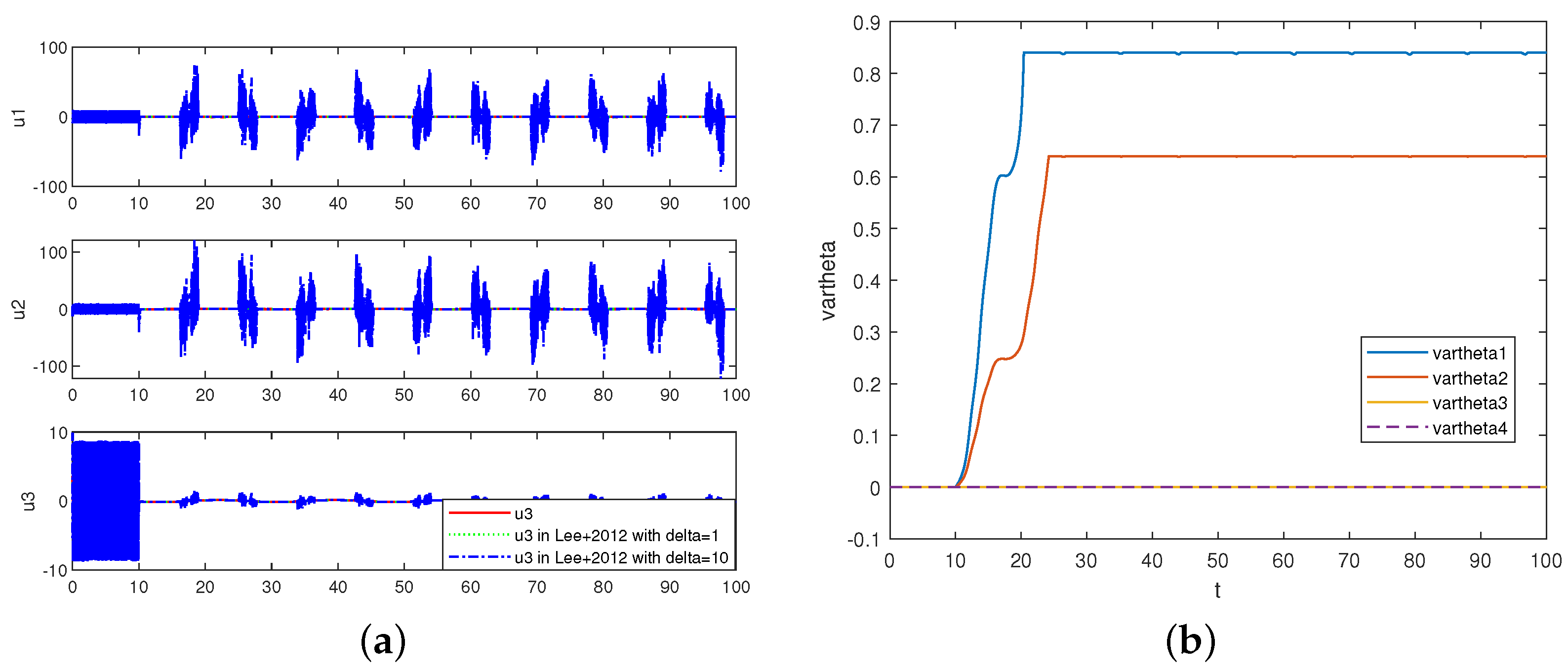
As shown in Figure 1 and Figure 2, the tracking performance of the designed AESO-based FTC method and the method in [28] with FTC is compared under the same system and control parameters. Since the method in [28] requires a known upper bound of interference, we choose 1 and 10 as the disturbance’s upper bounds. The given signal is w d = 0 3 × 1 ; thus, the angular velocity w quickly converges to zero in the first 10 s, as shown in Figure 1a, and as described in Figure 1b, the attitude error e R under the two control methods can exponentially converge to zero in the first 10 s. However, there exist small fluctuations when the fault occurrence time is 10 because of the existence of actuator faults; e R can converge to around zero, but the tracking error of the proposed method is smaller. However, from Figure 2a, when the upper bound of the disturbance is selected as 10, the chattering phenomenon happens. The control performance of the method in [28] depends on the upper bound of the disturbance, but it is hard to obtain the precise value in the real world. Figure 2b is the curve of the adaptive parameter ϑ . Since actuator failures occur in rotor 1 and rotor 2, the parameters ϑ 3 and ϑ 4 are always 0.
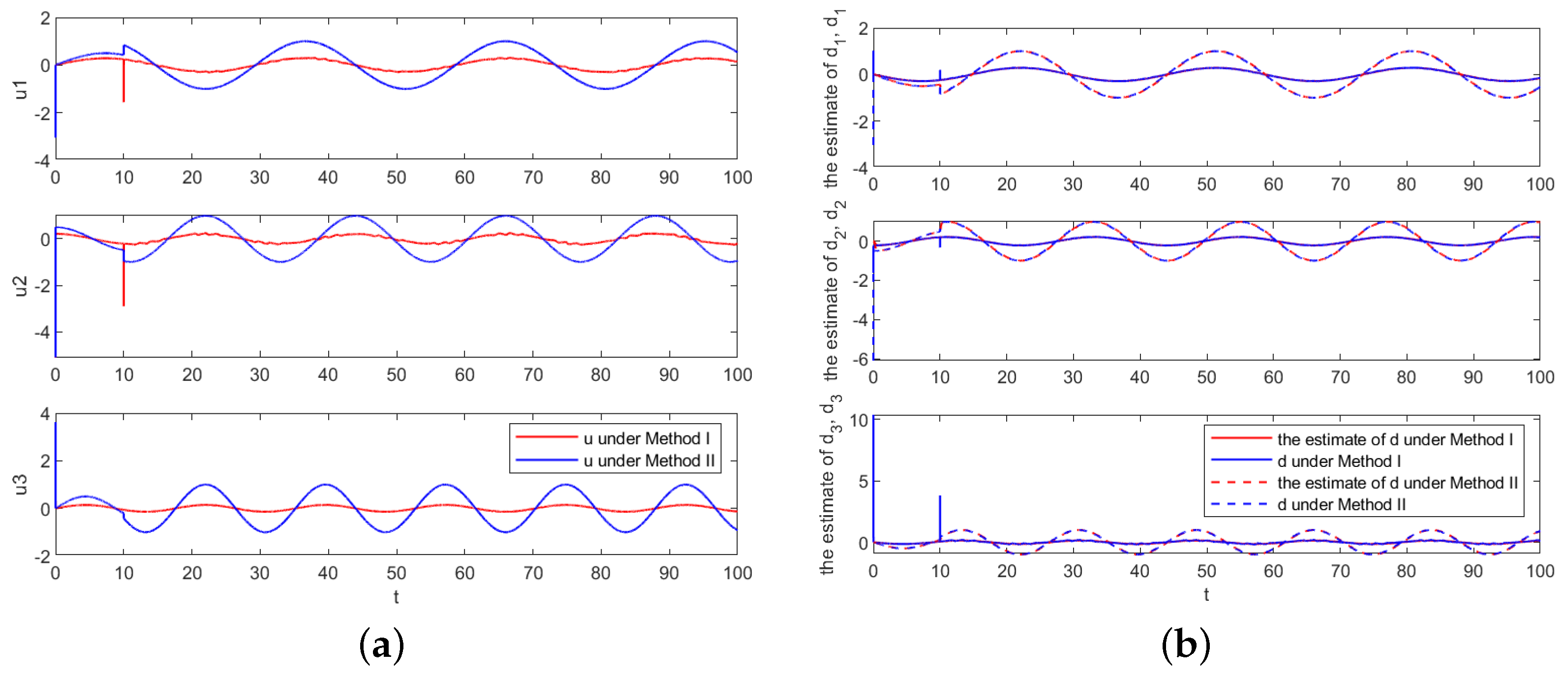
As shown in Figure 3 and Figure 4, the tracking performance of the proposed two control methods was compared when all parameters are the same. The two methods have different handling mechanisms for actuator faults. Method I is an AESO-based FTC method; the AESO estimates and compensates for uncertainty and external interference in the controller, which includes the fault tolerance control method. Method II is an AESO-based geometric control method; actuator failures are considered as part of the total disturbance, and the AESO estimates uncertainties, external disturbances and actuator failures and compensates for them in the geometric controller. Thus, as described in Figure 3a, while actuator failures (rotor 1 and rotor 2) occur in 10th s, method I is a fault-tolerant controller that is passive to deal with actuator faults. The angular velocity associated with rotor 1 and rotor 2 varies over a wide range; the angular velocity w varies less under method II. As shown in Figure 3b, the attitude error e R due to the AESO estimation error varies within a small range, and the attitude error associated with rotor 1 and rotor 2 varies within a wide range. According to Figure 4a,b, although all the parameters are the same, the control torque u and disturbance d are different due to the different control mechanisms.

5. Conclusions

In this paper, two different methods, including an AESOGFTC method and an AESO-based geometric control method, were proposed on SO(3) for UAVs. In the first method, an AESO-based control framework was constructed to estimate and compensate for the lumped disturbances with a time-varying observer gain which can effectively alleviate the peaking phenomenon. An FTC framework was proposed to cope with the occurrence of actuator faults which were modeled as a constant LOS. Another method employed an AESO to compensate for the lumped disturbances, which include endogenous uncertainties, exogenous disturbances and actuator faults. Finally, the error could exponentially converge to a bounded set. The proposed AESO-based controllers were designed without a known upper bound of the lumped disturbance. It is noted that the AESO-based control strategy does not depend on a precise system model; it can be applied to a wide spectrum of systems such as aircraft systems.

Author Contributions

Conceptualization, L.W.; methodology, L.W. and H.P.; software, L.W.; validation, L.W.; formal analysis, L.W.; investigation, L.W.; resources, L.W.; data curation, L.W.; writing—original draft preparation, L.W.; writing—review and editing, L.W., H.P. and Z.C.; visualization, L.W.; supervision, H.P. and Z.C.; project administration, H.P. and Z.C.; funding acquisition, H.P. All authors have read and agreed to the published version of the manuscript.

Funding

This work was funded by the Scientific Instruments Development Program of NSFC (61527810), the Fundamental Research Funds for the Central Universities (x2zdD2230070), National Key R&D Program of China (2023YFB4704900), the Aeronautical Science Foundation (20220056060001), and the New Generation of Information Technology Innovation Project, China University Innovation Fund (2022IT046).

Data Availability Statement

Data are contained within the article.

Conflicts of Interest

The authors declare no conflicts of interest.

Abbreviations

The following abbreviations are used in this manuscript:
UAVUnmanned Aerial Vehicle
AESOAdaptive Extended State Observer
NESONonlinear Extended State Observer
LESOLinear Extended State Observer
LOELoss of Effectiveness
FTCFault-Tolerant Control
SISOSingle-Input, Single-Output
MIMOMultiple-Input, Multiple-Output
AESOGFTCAESO-based Geometric Fault-Tolerant Control

References

  1. Lee, T.; Leok, M.; Mcclamroch, N. Control of complex maneuvers for a quadrotor UAV using geometric methods on SE(3). Mathematics 2010, 15, 391–408. [Google Scholar]
  2. Yun, Y.; Yang, S.; Wang, M.; Li, C.; Li, Z. High performance full attitude control of a quadrotor on SO(3). In Proceedings of the 2015 IEEE International Conference on Robotics and Automation (ICRA), Seattle, WA, USA, 26–30 May 2015; pp. 1698–1703. [Google Scholar]
  3. Alattas, K.A.; Vu, M.T.; Mofid, O.; El-Sousy, F.F.M.; Fekih, A.; Mobayen, S. Barrier Function-Based Nonsingular Finite-Time Tracker for Quadrotor UAVs Subject to Uncertainties and Input Constraints. Mathematics 2022, 10, 1659. [Google Scholar] [CrossRef]
  4. Gao, Y.; Zhang, H.; Chen, X.; Lu, T.; Tan, S.; Yang, H.; Gulliver, T.A. Tracking performance of the coaxial counter-paddle flight system using fractional active disturbance rejection controller. Appl. Math. Model. 2023, 121, 800–827. [Google Scholar] [CrossRef]
  5. Han, J.Q. A class of extended state observers for uncertain systems. Control. Decis. 1995, 10, 85–88. [Google Scholar]
  6. Han, J.Q. Active Disturbance Rejection Control Technique—The Technique for Estimating and Compensating the Uncertainties; National Defense Industry Press: Beijing, China, 2008; pp. 197–270. [Google Scholar]
  7. Han, J.Q. From PID to active disturbance rejection control. IEEE Trans. Ind. Electron. 2009, 56, 900–906. [Google Scholar] [CrossRef]
  8. Guo, B.Z.; Zhao, Z. On convergence of nonlinear extended state observer for multi-input multi-output systems with uncertainty. IET Control Theory Appl. 2012, 6, 2375–2386. [Google Scholar] [CrossRef]
  9. Guo, B.Z. Scaling and bandwidth-parameterization based controller tuning. In Proceedings of the 2003 American Control Conference, Denver, CO, USA, 4–6 June 2003; pp. 4989–4996. [Google Scholar]
  10. Shao, X.; Zhang, W.; Zhang, W. Improved prescribed performance anti-disturbance control for UAVs. Appl. Math. Model. 2021, 97, 501–521. [Google Scholar] [CrossRef]
  11. Pu, Z.; Yuan, R.; Yi, J.; Tan, X. A class of adaptive extended state observers for nonlinear disturbed systems. IEEE Trans. Ind. Electron. 2015, 62, 5858–5869. [Google Scholar] [CrossRef]
  12. Xue, W.; Bai, W.; Yang, S.; Song, K.; Huang, Y.; Xie, H. ADRC with adaptive extended state observer and its application to air-fuel ratio control in gasoline engines. IEEE Trans. Ind. Electron. 2015, 62, 5847–5857. [Google Scholar] [CrossRef]
  13. Wu, X.; Wang, C.; Hua, S. Adaptive extended state observer-based nonsingular terminal sliding mode control for the aircraft skin inspection robot. J. Intell. Robot. Syst. 2020, 98, 721–732. [Google Scholar] [CrossRef]
  14. Tang, X.; Tao, G.; Joshi, S.M. Adaptive actuator failure compensation for nonlinear MIMO systems with an aircraft control application. Automatica 2007, 43, 1869–1883. [Google Scholar] [CrossRef]
  15. Lu, K.; Xia, Y. Adaptive attitude tracking control for rigid spacecraft with finite-time convergence. Automatica 2013, 49, 3591–3599. [Google Scholar] [CrossRef]
  16. Shen, Q.; Wang, D.; Zhu, S.; Poh, E.K. Inertia-free fault-tolerant spacecraft attitude tracking using control allocation. Automatica 2015, 62, 114–121. [Google Scholar] [CrossRef]
  17. Avram, R.C.; Zhang, X.; Muse, J. Quadrotor actuator fault diagnosis and accommodation using nonlinear adaptive estimators. IEEE Trans. Control Syst. Technol. 2017, 25, 2219–2226. [Google Scholar] [CrossRef]
  18. Avram, R.C.; Zhang, X.; Muse, J. Nonlinear adaptive fault-tolerant quadrotor altitude and attitude tracking with multiple actuator faults. IEEE Trans. Control Syst. Technol. 2018, 26, 701–707. [Google Scholar] [CrossRef]
  19. Li, B.; Hu, Q.; Yu, Y.; Ma, G. Observer-based fault-tolerant attitude control for rigid spacecraft. IEEE Trans. Aerosp. Electron. Syst. 2017, 53, 2572–2582. [Google Scholar] [CrossRef]
  20. Ran, D.; Chen, X.; de Anton, R.; Xiao, B. Adaptive extended-state observer-based fault tolerant attitude control for spacecraft with reaction wheels. Acta Astronaut. 2018, 145, 501–514. [Google Scholar] [CrossRef]
  21. Wang, X.; Tan, C.P. Fault-tolerant spacecraft attitude control under actuator saturation and without angular velocity. Int. J. Robust Nonlinear Control 2019, 29, 6483–6506. [Google Scholar] [CrossRef]
  22. Mallavalli, S.; Fekih, A. A fault tolerant tracking control for a quadrotor UAV subject to simultaneous actuator faults and exogenous disturbances. Int. J. Control. 2020, 93, 655–668. [Google Scholar] [CrossRef]
  23. Najafi, A.; Vu, M.T.; Mobayen, S.; Asad, J.H.; Fekih, A. Adaptive Barrier Fast Terminal Sliding Mode Actuator Fault Tolerant Control Approach for Quadrotor UAVs. Mathematics 2022, 10, 3009. [Google Scholar] [CrossRef]
  24. Liu, Z.B.; Wang, L.; Song, Y.C.; Dang, Q.Q.; Ma, B.D. Fault diagnosis and accommodation for multi-actuator faults of a fixed-wing unmanned aerial vehicle. Meas. Sci. Technol. 2022, 33, 075903. [Google Scholar] [CrossRef]
  25. Xu, J.; Wang, L.; Liu, Y.; Xue, H. Finite-time prescribed performance optimal attitude control for quadrotor UAV. Appl. Math. Model. 2023, 120, 752–768. [Google Scholar] [CrossRef]
  26. Bullo, F.; Murray, R.M. Proportional Derivative (PD) Control on the Euclidean Group; California Institute of Technology: Pasadena, CA, USA, 1995; Available online: https://citeseerx.ist.psu.edu (accessed on 18 March 2020).
  27. Lee, T. Exponential stability of an attitude tracking control system on SO(3) for large-angle rotational maneuvers. Syst. Control Lett. 2012, 61, 231–237. [Google Scholar] [CrossRef]
  28. Lee, T. Robust adaptive geometric tracking controls on SO(3) with an application to the attitude dynamics of a quadrotor UAV. In Proceedings of the 50th IEEE Conf. on Decision and Control and European Control Conference, Orlando, FL, USA, 12–15 December 2012. [Google Scholar]
  29. Silverman, L.M. Transformation of time-variable systems to canonical (phase-variable) form. IEEE Trans. Automat. Control 1966, 11, 300–303. [Google Scholar] [CrossRef]
  30. Zhu, J. A unified spectral theory for linear time-varying systems-progress and challenges. In Proceedings of the IEEE Conference on Decision and Control, New Orleans, LA, USA, 13–15 December 1995. [Google Scholar]
  31. Ma, K. Comment on ‘Quasi-continuous higher order sliding-mode controller for spacecraft-attitude-tracking maneuvers’. IEEE Trans. Ind. Electron. 2013, 60, 2771–2773. [Google Scholar] [CrossRef]
  32. Khalil, H. Nonlinear Systems, 2nd ed.; Prentice Hall: Hoboken, NJ, USA, 1996. [Google Scholar]
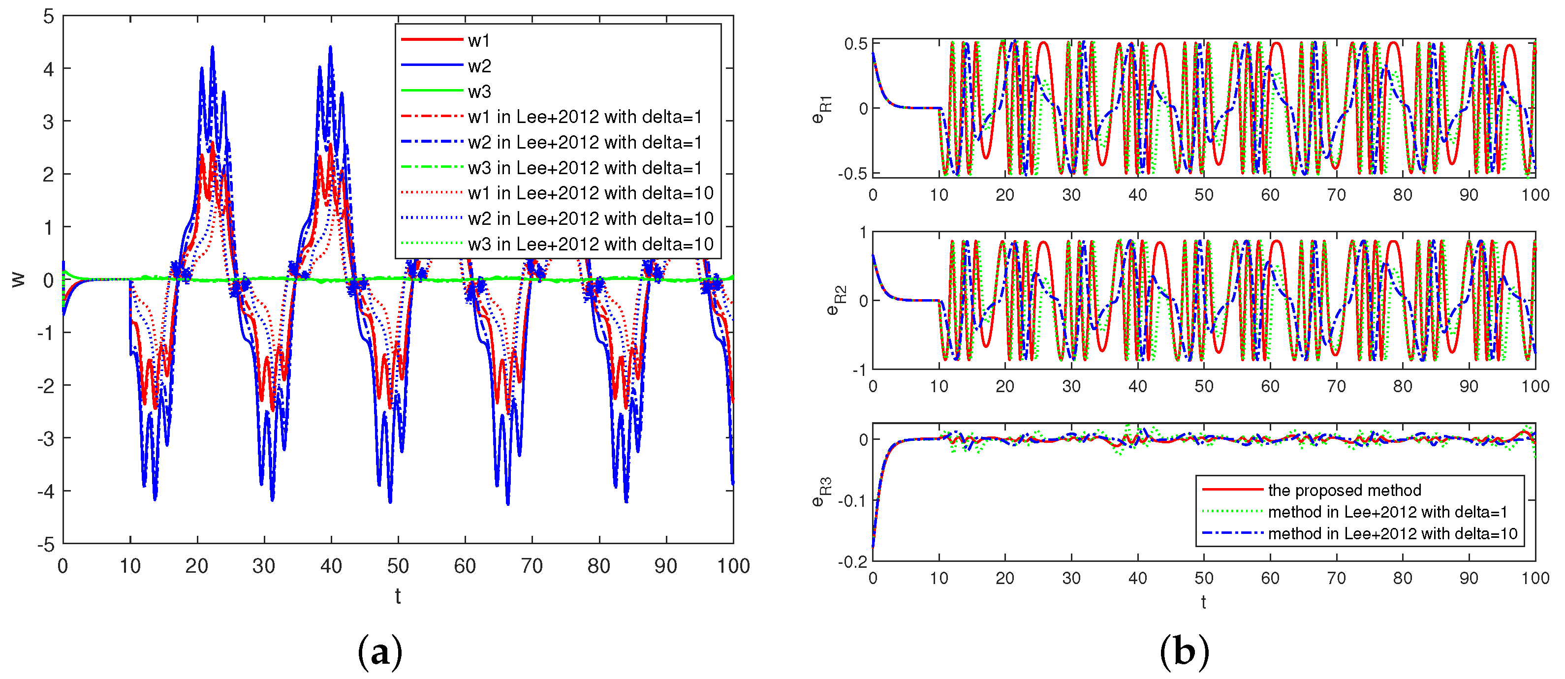
Figure 1. (a) The angular velocity w. (b) The attitude error vector e R .
Machines 12 00047 g001
Figure 2. (a) The control torque u. (b) The adaptive parameter ϑ .
Machines 12 00047 g002
Figure 3. (a) The angular velocity w under methods I and II. (b) The attitude error vector e R under methods I and II.
Machines 12 00047 g003
Figure 4. (a) The control torque u under methods I and II. (b) The lumped disturbance d and its estimate d ¯ under methods I and II.
Machines 12 00047 g004
Disclaimer/Publisher’s Note: The statements, opinions and data contained in all publications are solely those of the individual author(s) and contributor(s) and not of MDPI and/or the editor(s). MDPI and/or the editor(s) disclaim responsibility for any injury to people or property resulting from any ideas, methods, instructions or products referred to in the content.