Article

Universal Jamming Gripper: Experimental Analysis on Envelope and Granular Materials

by
Ignacio de Rodrigo
*,
Jorge Belart
and
Alvaro J. Lopez-Lopez
Institute for Research in Technology, ICAI School of Engineering, Comillas Pontifical University, 28015 Madrid, Spain
*
Author to whom correspondence should be addressed.
Machines 2024, 12(1), 52; https://doi.org/10.3390/machines12010052
Submission received: 4 December 2023 / Revised: 3 January 2024 / Accepted: 9 January 2024 / Published: 11 January 2024
(This article belongs to the Section Material Processing Technology)

Abstract

:
This article presents a materials optimization for the universal jamming gripper, one of the most versatile tools for robotic grasping. For this purpose, we analyze both the granular interior material and its surrounding deformable envelope. We combine four different granulate sizes (glass balls ranging from 0.2 to 1 mm) with four envelope materials (three silicones and latex), resulting in 16 prototype combinations. We use a tensile test machine to recreate the robot’s vertical movement in a real scenario situation. Thus, we can have precise control of the gripper’s immersion depth, forces, and displacements. Thanks to the tensile test, we extract the critical parameters to evaluate every material combination and the gripper’s performance. Therefore, we provide an experimental guide to selecting the right materials and rule out bad combinations for soft robots and specifically for the universal jamming gripper.

1. Introduction

Most of the parts and components in industrial assembly lines appear inside boxes. Robots are familiar with manipulating them in well-organized and structured scenarios. Nevertheless, the interior of these boxes is chaotic and supplier-dependent. Thus, interacting with industrial parts becomes a non-structured and complicated scenario for robots. Automated systems might deal with pick&place, opening boxes, or depalletizing clamped parts. In addition, the bill of materials can grow exponentially depending on the industry sector. Therefore, robots must deal with different geometries, textures, weights, and other part restrictions. Simultaneously, the industrial sector demands minimum cycle times and increasingly independent systems. These restrictions mean that robot systems must be fast, effective, and versatile.
Academia and industry have established common spaces to share ideas about tackling robot warehouse automation [1,2]. Nevertheless, the issue is still far from finding a general solution: component geometries range from large-size elements such as bottles to tiny parts such as threaded nuts. In addition, chaotic scenarios show different entropy degrees. Entropy describes the lack of structure and depends mainly on shapes. Thus, the scenarios a robot must face may include unstable arrangements (Figure 1A) vertical overlaps (Figure 1B) or coplanar overlap (Figure 1C). These scenarios mean the robot might displace a component when trying to catch it or not even be able to approach the part because the grasping point is unreachable (see, for instance Figure 1C, where the center object is unreachable for a two-jaw parallel gripper). Therefore, entropy could make a whole grasp cycle unsuccessful.
Thus, robots need to include feedback when they move to react on the fly, so some solutions include onboard cameras. In addition, robot grippers must include force feedback when grasping soft or delicate components such as foams or plastics [3]. Finally, robots might face restrictive scenarios for their kinematics, so Reinforcement Learning (RL) has emerged as a new tool to drive robotic arms in challenging scenarios [4]. The coordination of these solutions shows strategies to reliably catch parts in chaotic scenarios and approach the unsolved question of how to catch parts individually when chaos appears. Over the last several years, the following areas have brought improvements to solve this open question:
  • Data acquisition: Automated stations usually rely on RGB cameras to input data into the systems. These devices can feed deep learning models to estimate object positions [5] or contours [6] and, thus, command the robot’s movement [7]. Depth images and point clouds are a standard complement to RGB images. With this information, models can also estimate the orientation of the objects and improve versatility [8].
  • Grasping point strategies: Some models rely on the power of Convolutional Neural Networks (CNNs) to determine the quality of several grasping points for an object [9]. On other occasions, the model first estimates the location and orientation of the object and then, with this information, locates the grasping point. In most cases, synthetic data generation has reached a prominent position as a tool to create and label datasets [10]. Finally, in those cases where the positioning or the complexity of the part is high, some solutions explore the coordination of two robots [11].
  • Robot kinematics: For the last few decades, RL has mimicked the mammal’s brain response to positive stimuli. RL has become a popular tool to orchestrate robotic movement based on trial and error as well as adequate reward policies. Some achievements include reaching tasks, pick&place tasks, or even higher-level tasks such as opening doors [4]. Again, the experience gathered through virtual simulators has reached a prominent relevance [12], although some approaches have opted to acquire real-life experience [13]. In addition to these techniques, other projects have developed ad hoc strategies for particular picking tasks [14] or multiagent strategies for static and dynamic collision avoidance [15].
  • Gripper designs: Some of the most important developments have come from the soft robotics field [16]. This technique replicates nature to reproduce soft bodies with no rigid structure [17]. The main characteristics describing these bodies are silicones as materials and air pressure as the actuation system to generate movement [18,19]. In addition, some solutions have implemented paper folding and paper cutting techniques (origami and kirigami). These techniques have provided both grippers with larger contact surfaces [20] and grippers capable of adapting their geometry and passively modulating the force they apply [3]. Finally, also inspired by nature, other projects base the gripping ability on geckos’ traction technique. Here, the gripper is a thin sheet of deformable biphase material that changes its properties by heat application. Temperature variations produce phase changes that increase Van der Waals forces, allowing this prototype to grasp different geometry objects [21].
These strategies help solve some of the most complex scenarios of grasping objects. Nevertheless, the industry is not only interested in robots gripping parts in chaotic scenarios. The industry requires individual gripping so that the number of parts is under control at any given time. Thus, robots can create batches with the exact number of parts to precisely feed the assembly line. However, some of the mentioned solutions require a significant time and money investment when implemented or are not suitable for generalization.
We believe that gripper development needs more prominence to reach generalist solutions. Thus, we have developed research to study alternative gripping tools prior to this publication. In that research, we aimed to detect the tool with the most significant potential to grasp parts individually. We defined our specific parameters and developed an ad hoc decision matrix to judge the best suitable solution, as the literature does not provide an adequate framework for a selective grasping application [22]. We include this outcome in the Appendix A. In this prior research, we concluded that the best tool for this purpose is the jamming effect gripper, a soft robotics solution [23]. The physical principle behind this soft robotic manipulator is known as the jamming effect. The gripper can work in two modes or phases. In the first phase, in which the inner pressure is the atmospheric one, the gripper behaves as a relaxed body that can adapt to any geometry. In the second phase, the granulates inside the envelope are compact since the vacuum effect removes the air in the interior. Here, the gripper is petrified, and the jamming effect arises; the manipulator can then take advantage of its ad hoc shape to potentially grasp any object it covers. Figure 2 shows the universal jamming gripper used. Its geometry is further described in Section 3.1.
Figure 2. Universal jamming gripper. Two key elements comprise the robotic manipulator: the white translucent envelope and the granulate material it wraps (refer to Figure 3). In addition, the image also shows the upper attaching part, which contains the air filter and allows for a hermetic seal (refer to Figure 4).
Machines 12 00052 g002
This gripper can adapt its shape to different geometries and provide high-quality grasps. In addition, there is the potential for embedding tactile sensors on it [24,25]. These properties make this gripper a great candidate for solving the chaotic scenario problem, including knowing the number of parts the gripper touches and where they are located.
As a previous step in developing these concepts, we study the gripper’s components: both the inner granular one and the deformable material that covers it. In this way, we aim to find a good combination for different use cases where object properties (weight, geometry, or rigidity) vary.
We summarize our main contributions as:
  • Primary Contribution: We provide a robust empirical foundation for material selection in applications involving elements of soft robotics, particularly those requiring lax compression, vacuum application, and traction under the jamming effect, such as in robotic grasping scenarios.
  • Unique Gripping Cycle Analysis: Unlike other studies, this research closely replicates the gripping cycle of a robot, including lax compression (simulating grip deformation) and traction with an active jamming effect (representing the maximum gripping force). We test the prototypes with this optimization goal, and our methods and designs align with this goal.
  • Introduction of a New Metric: We introduce an unexplored metric in this context—the energy absorbed in the grip—proposed as a quality measure for assessing grip efficacy.
  • Extensive Material Combination Study: We research an extensive range of material combinations (16 in total), a significantly broader scope than most literature, examining both filler (four glass ball diameters) and enveloping materials (four different materials).
  • Detailed Analysis of Filler Material Dimensions: Unlike common studies that focus on glass balls larger than 1 mm, this research delves into finer details, analyzing up to three sizes of glass beads below 1 mm, enhancing material optimization sampling.
  • The Thinner the Better for Optimizing Weight Lifting: Our research suggests that envelopes with thinner walls allow the internal granulate to manifest in the external texture of the prototype, increasing its coefficient of friction. In other words, the selection of internal material not only affects the forces that can be developed during the jamming effect phenomenon (internal influence) but also has a very notable effect on what happens in the prototype piece contact (external influence) when the envelope wall is thin.

2. Related Work

The jamming effect is a phenomenon that appears in granular materials when the interaction of the particles prevents their movement. These particles’ size order of magnitude may vary between micrometers (coffee grounds when packed) to meters (rock jetties). Jaeger [26] reviewed the scope of application of the jamming effect and summarized it in three major fields: architecture [27], energy dissipation, and soft robotics. On the other hand, soft robotics is the group of actuators based on biology that replicates soft bodies with variable stiffness. Previous works introduced extensive revisions on soft robotics: Kim et al. [17] made a comprehensive review of bio-inspired soft robots, while Shintake et al. [16] focused on the application of this technology to robot grippers. In addition, Fitzgerald et al. [28] merged both concepts (jamming effect plus soft robotics) and developed a specific review on the jamming effect on soft robots.
Brown et al. [23] introduced one of the most relevant prototypes in the soft robotics gripper field: the universal jamming gripper. This gripper comprised a flexible envelope plus a granular material in the interior: the conjunction of materials allowed the gripper to adapt to any geometry. Once deformed, this gripper can grasp the object by vacuuming the interior chamber and thus increasing the gripper stiffness. Some subsequent works included more refinements as positive pressure [29]. This feature allowed the breaking of the jammed structure when no vacuum was applied, thus recovering the relaxed gripper shape. Due to the versatility of the gripper and its agnosticism to object geometry, Amend et al. [30] attempted to commercialize it.
In the field of soft robotics, vacuum is the most commonly used driving force to produce the jamming effect. Nevertheless, other works have proved that this technique is not the only one capable of generating it. Choi et al. [31] developed a visually similar gripper to Brown’s. However, instead of granular material as filler, they used a magnetorheological fluid, and instead of vacuum, they used a magnetic field to solidify the gripper. In addition, Choi et al. also studied the effects of including magnetic properties in the elastic envelope. In line with this methodology, Nishida et al. [32] studied the impact of non-magnetic particles on the magnetorheological fluid. Here, they looked at the influence of particle materials and sizes on the gripper’s behavior. In addition to this technique, Li et al. [33] observed that external forces applied to a confined granular material could also obtain the jamming effect. In this way, they presented a prototype where inflatable soft actuators put pressure on the filler chamber to modify robot stiffness. Bartkowski et al. [34] presented the known e-morph, an electromagnetically-controlled actuator, that combines a granular core with a silicone outer shell, featuring channels filled with liquid metal. This design enables rapid changes in shape and stiffness, driven by electromagnetic forces and a jamming mechanism.
Other works have focused on the independent influence of both the granular material and the flexible envelope. Regarding the granular material, Götz et al. [35] studied the impact of deformable particles on the maximum weight a universal jamming gripper could lift. In addition, Loeve et al. [36] studied the influence of different granulate geometries and sizes to maximize the bending moment in worm-inspired soft robots for endoscopic application. Furthermore, Misking and Jaeger [37] developed an evolutionary algorithm to design molecule-style particles. Thus, they could control the compaction factor by changing the number and orientation of spheres comprising a particle. In addition, Hudson [38] studied a range of granular materials, including various sizes of glass beads (most with diameters over 1 mm), silica blasting media, sand, and ground coffee, subjecting them to different vacuum pressures. His experiments were conducted under compressive loads, thus not covering traction tests.
Regarding envelope studies, Howard et al. [39] developed a genetic algorithm to design the universal jamming gripper’s geometry. In addition, they used a 3D printer to manufacture the silicone sac, while most soft robotics manufacturing processes use molds. Additionally, Jiang et al. [40] studied the influence of envelope materials on the mechanical performance of soft tubular specimens. Finally, Xiao et al. [41] worked on the geometry of soft actuators. As a result, they developed pneumatic twisting muscles with helical geometries.
Regarding the jamming effect, several other research studies and soft robot prototypes include its properties. Wei et al. [42] proposed a three-finger gripper that complies with objects’ geometries better than traditional stiff finger grippers, while Cheng et al. [43] developed a trunk-inspired hyper-redundant manipulator. Furthermore, Licht et al. [44] applied the universal jamming gripper to collect objects in deep-sea scenarios. In addition, Cheng et al. implemented a prosthetic hand system by using the same gripper prototype [45]. Finally, some projects have mixed the capabilities of soft robots and the jamming effect with state-of-the-art deep learning algorithms. Thus, Jiang et al. [46] took advantage of the radial symmetry and deformation of the universal jamming gripper to develop a hardware-agnostic algorithm for robust grasping.
While state-of-the-art research in material optimization for jamming effects has been extensive and diverse, it often varies in operational conditions. Some studies focus on prototypes operating under compressive loads with jamming effect [38], others on bending loads [36], and some integrate magnetic particles [31]. As a result, the outcomes of these studies are highly influenced by their specific optimization goals.
On the other hand, our research is specifically tailored for robotic gripping, requiring a precise operational sequence for effectiveness:
  • Gripper compression against the part without the jamming effect;
  • Creation of a vacuum, preparing the gripper for action under the jamming effect;
  • Traction while the gripper is engaged with the object, with the jamming effect active.
This operational sequence highlights the unique application of the jamming effect in robotic gripping. Our focus is on traction, which distinguishes our approach from studies centered on other forms of stress, such as bending or compression, under the jamming effect.

3. Methodology

As Amend et al. [29] stated, three physical effects can contribute to successfully grasping an object using a universal jamming gripper: friction force (microscopic level), geometry irregularities (macroscopic level), and vacuum cameras. Figure 5 illustrates these physical phenomena.
Different research projects prove that the jamming effect differs based on the material used [35,36,40]. Nevertheless, these works have always tested both materials (granular material plus envelope) in a separate way. Here, we test different options by changing both elements to find optimum combinations.
Thus, the materials used to manufacture the envelopes are latex and three different silicones (Shore 00-10, Shore 00-50, and Shore A-25). As shown in Table 1, every envelope has a particular wall thickness due to manufacturing restrictions and tearing resistance. In addition, Table 1 shows other silicone features, such as density and roughness.
Regarding the granular material, this research is only interested in analyzing grain size comparison. Therefore, choosing a unique material for the different diameter samples is critical. Using the same granular material allows for exploring the size influence on gripper performance without introducing any bias related to other granulate properties. We explored several material options, including organic ones like beach sand and synthetic ones like silica gel. We chose to use glass balls since this material allowed us to scan the diameters of interest for this research, and the needed formats were readily available on the market. Figure 3 shows the different sizes of glass balls used under a 20× zoom magnification. Although the granular material used in this study is segmented into four different size groups, polydispersity is a potential phenomenon that could arise. This phenomenon, as studied by Hermes and Dijkstra [47], suggests that the occurrence of different particle sizes can lead to higher packing densities and alter the mechanical behavior of the prototypes: a higher packing density results in more contact between particles and, potentially, more frictional forces arise between them in the prototype’s interior. Although this behavior might be considered beneficial in certain scenarios, this study opts to analyze the different filler sizes separately. To confirm this, a sampling of the glass balls was performed under a microscope (Figure 3) to verify that the dimensions of the glass beads indeed matched the manufacturer’s specifications. While it is true that some beads of different size might appear, their population density was not very notable, thus leaving the effects of polydispersity outside the scope of this work.

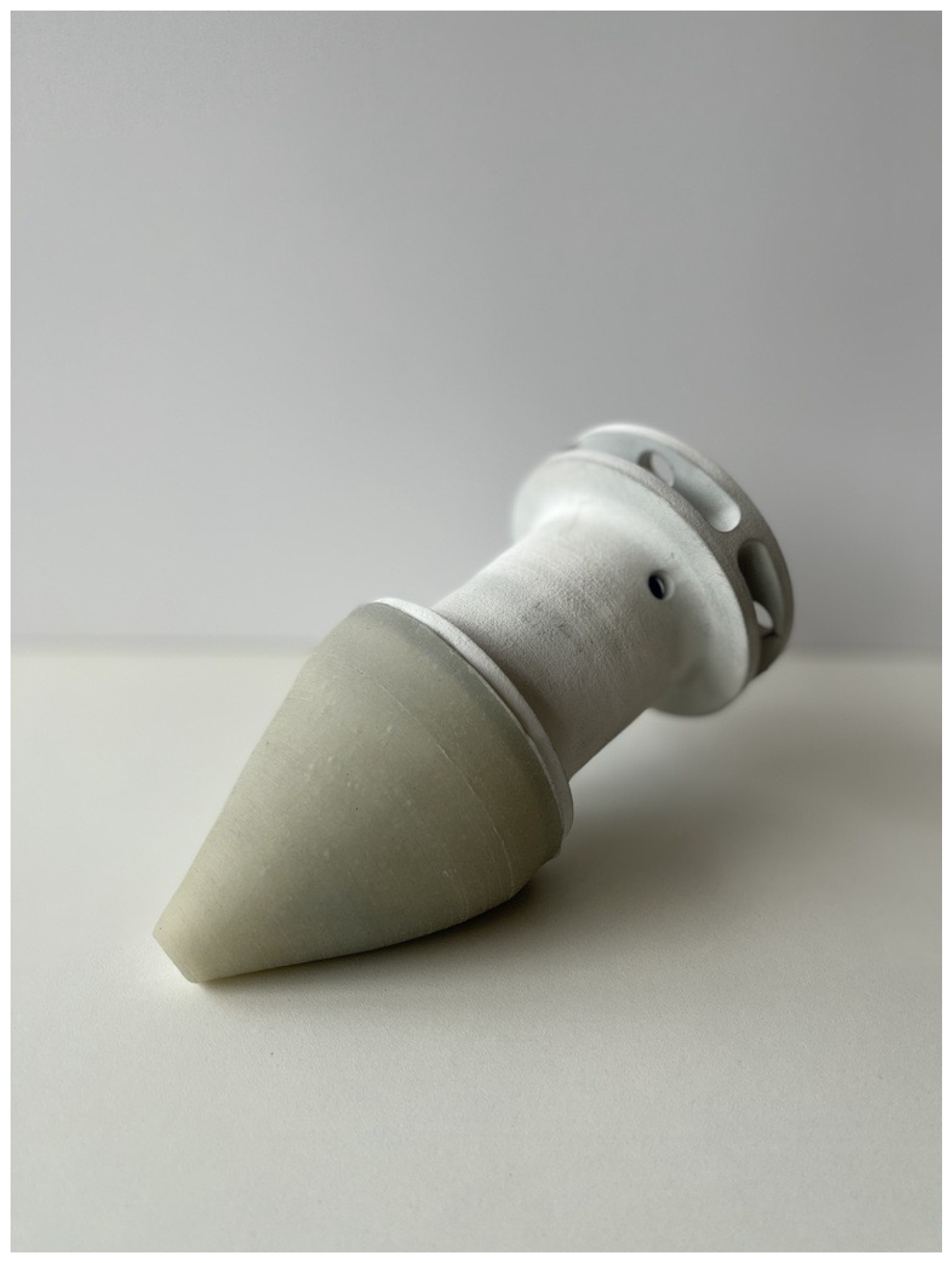
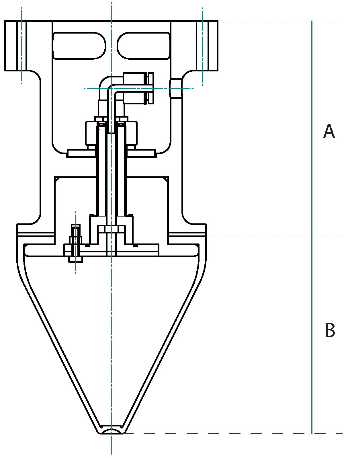
3.1. Gripper Geometry

As shown in Figure 4, two subassemblies comprise the prototype: the rigid support and the deformable body. At the top is the rigid support, which anchors the gripper to the robot or the tensile tester. In addition, the rigid support includes the necessary components to guarantee the hermetic sealing of the deformable body and the vacuum filter. We include a detailed exploded-view assembly drawing as Supplementary Materials.
On the other hand, the soft body comprises the two elements relevant to this research: the envelope and the granulate material. The envelope houses the different samples of granulate material shown in Figure 3. As previously mentioned, the materials considered for the envelope are flexible and deformable: silicone and latex (Table 1). The geometry of the envelope is conical in such a way that it is possible to grip parts of different sizes: from the smallest (using the gripper tip to avoid excessive compression) to the largest (compressing the gripper to the base, where the diameter is more prominent, and the contact region increases). The choice of this gripper geometry is motivated by its potential pliability, its collapse capabilities (which favor the embracing of the mushroom-shaped test part), and its radius reduction to minimize volume and weight. After several iterations in which we changed the aspect ratio of the tool (radius vs. length), we opted for this geometry that satisfied our criteria. Furthermore, as Brown et al. [23] did with their original design, we chose a geometry with radial symmetry to favor the kinematics of any potential robot. The envelope tip includes a slight concavity that aims to ease the collapse of the soft body when it makes contact with any object. On the other hand, the top of the envelope includes a lip that, compressed against the upper body, allows for a tight seal of the vacuum chamber. The silicone envelopes are manufactured by molding, while the latex version requires an immersion technique due to curing limitations.

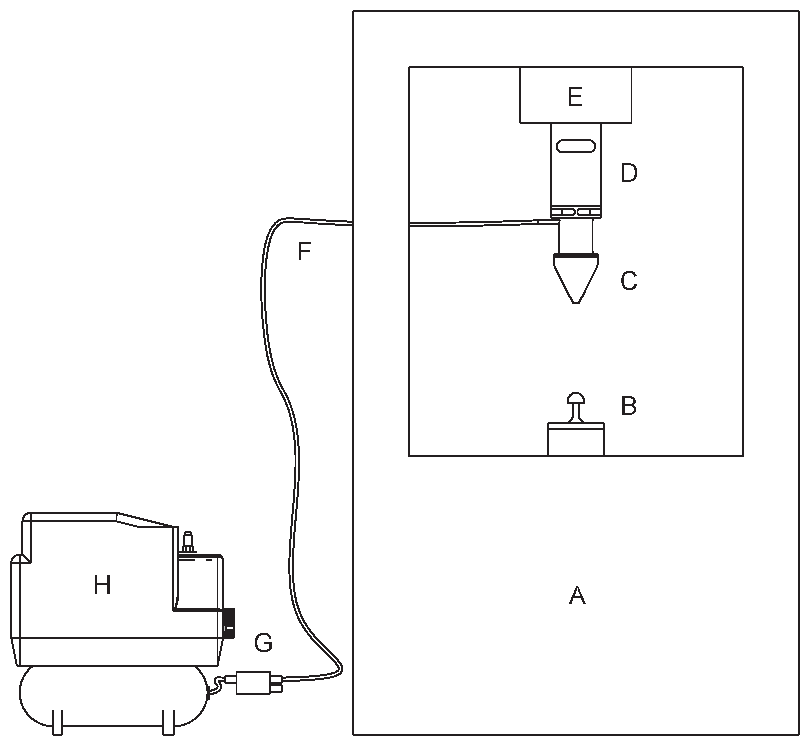
3.2. Setup Description

The testing setup is composed of several elements; Figure 6 shows them and their arrangement. The elements involved in the vacuum effect generation are an air compressor and a Venturi device. The air compressor works in the 6 to 8 bar range. The Venturi device, attached to the compressor’s output, ensures a negative pressure of at least 0.8 bar at every moment. A vacuum line connects the pressure system to the gripper. The tensile force tester allows for precise vertical placement of the gripper, constant velocity during tests, and force versus displacement recording. The load force sensor used has a maximum value of 0.5 KN. The tester’s upper part is the moving one, and the force sensor and, in turn, the gripper attaches to it. On the other hand, the test specimen is located at the fixed lower part of the machine.
We designed the test specimen according to the Amend et al. findings [29] displayed in Figure 5. As presented in Section 3, the three phenomena allowing the gripper to grasp objects are: static friction, geometric constraints, and vacuum chambers. Since we want to test the prototype’s resilience, the test specimen’s shape tries (on purpose) to reproduce the worst-case scenario. This scenario means that the gripper cannot always rely on favorable geometric constraints or vacuum chambers since the most complicated parts to grasp hardly ever include these features. Thus, the gripper can only rely on the traction force between the gripper and the specimen’s surface and, occasionally, on the geometric constraints its mushroom shape provides. To recreate the desired behavior, we designed the specimen by focusing on the mentioned parameters—static friction, geometric constraints, and vacuum chambers—as follows.
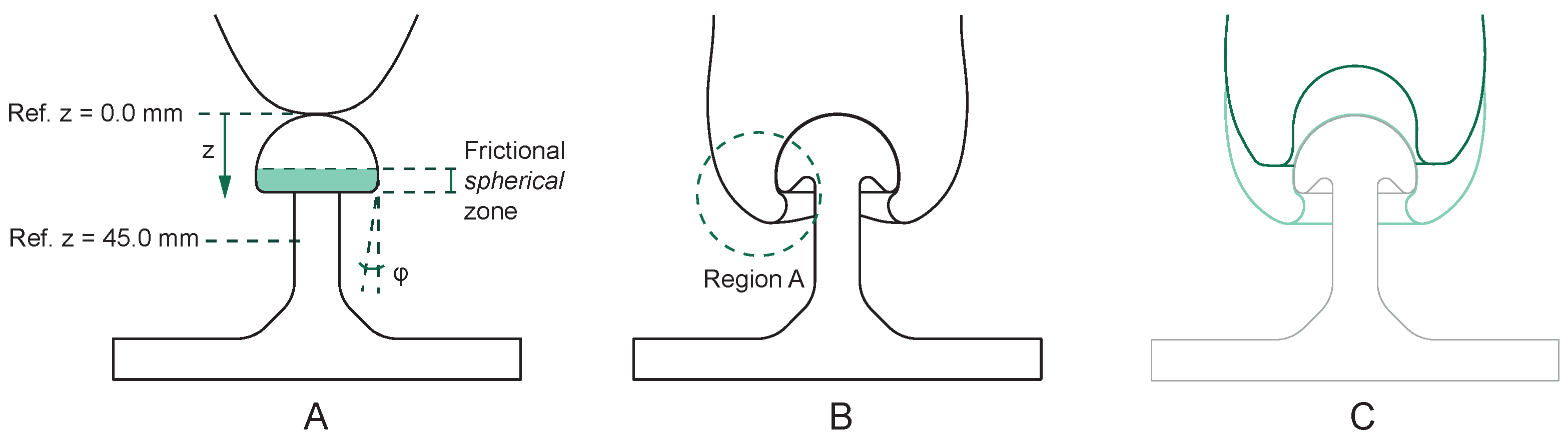
  • Static friction: The machine used to manufacture the specimen is a Multi Jet Fusion 3D printer. The material used is powdered nylon PA12. The combination of the process and the material results in a linear roughness of 78 μm, providing an isotropic and uniform friction factor along the contact area. The contact zone provided by the specimen is limited to the region marked in green in Figure 7A.
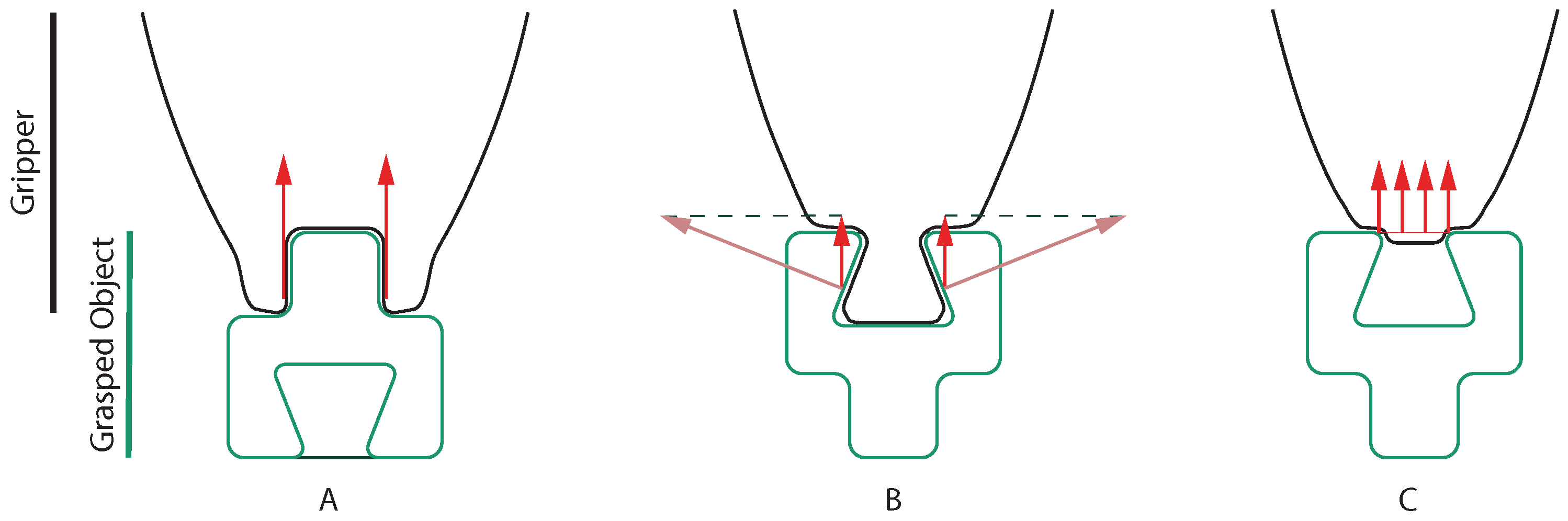
  • Geometric constraints: We wanted to reward only those gripper combinations with good deformation behavior. Thus, we designed the specimen so that there are no easily reachable geometric constraints. Instead, we hid the constraint behind the convexity of the mushroom head. Figure 7A defines the angle φ . This parameter describes the ability of the gripper to occupy the geometric constraint provided by the specimen. Figure 7B explicitly shows how prototypes can occupy the gripper zone called Region A. Only those prototypes with adequate fluidity and pliability can reach this zone. This fact allows their performance to improve. As shown in Figure 8, prototypes manage to increase the gripping distance d and maximize the stored energy E (both parameters are defined in Figure 9).
  • Vacuum chambers: We decided not to consider any vacuum chamber effect. To prevent the formation of any pressure chamber, we included a convex shape at the top of the test specimen.

3.3. Pull-Off Force Test

The tensile test machine can show the features of every gripper by performing a (conceptually similar) stress–strain test. The main difference here is that the sample specimen is not a single metal or composite part; instead, it is two detachable parts: the soft gripper and the mushroom-shaped part. The tensile tester machine pulls until both parts, initially attached, lose contact. Thus, the pull-off force test can evaluate the grippers’ extreme case abilities. Here, the candidate grippers’ parameters to be optimized are:
  • Lifted weight: This variable is the maximum weight a gripper can lift. The gripper reaches this value during the tension testing phase.
  • Stored energy: The second relevant parameter is the stored energy in the pull-off process. This value means the energy needed to pull off the gripper from the test specimen, i.e., the energy required to make any grasped object drop. This parameter is relevant since it expresses the quality of the grasp. In a real-life scenario, when a robotic arm attaches to the gripper, this external energy might be revealed in vibrations or inertial forces associated with linear accelerations and rotational movements. The higher the energy value is, the better the quality of the grasps.
  • Deformation force: This parameter is the force a gripper needs to adapt its initial shape to the desired object. The tensile test machine obtains this value during the compression phase when the gripper is relaxed. The deformation force value is relevant since some industrial applications require robotics systems to grasp delicate parts such as brittle or deformable objects.
Developing these tests means following a precise sequence of steps. The following methodology guarantees the repeatability of the tests and makes possible the comparison between the different material combinations:
  • First step: The volume of glass balls inside the envelope must be uniform for every test combination and equal to 153 mL. This is the theoretical interior volume (measured in CAD) that the envelope can wrap.
  • Second step: The envelope must be clean every time a test starts. Cleaning it with alcohol guarantees that no particle from the surrounding environment is attached to the surface, and thus, no friction losses happen.
  • Third step: Once the surface is dry, the upper part of the tensile tester machine starts its movement downwards. This movement compresses the gripper against the mushroom-shaped test specimen while the gripper is still relaxed. The movement stops when the displacement is equal to 45 mm from the reference position. Figure 7A shows the reference position ( z = 0 when the gripper tip is tangent to the mushroom head). The maximum displacement any gripper can handle without entering the nonlinear compression force region is 45 mm (Figure 10 indicates the typical gripper behavior during the compression phase). The downwards velocity of the gripper at this stage is 250 mm/min.
It is also relevant to remark that a displacement d on the tensile tester upper part is not equivalent to the same displacement on the gripper prototype ( d ). Even though both parts are attached, the prototype’s deformation properties (for instance, envelope pliability or granulate fluidity) lead to different displacement correlations, i.e., d d .
Figure 8 illustrates this. Even though the tensile tester’s upper part always moves 45 mm downwards, the gripping distance d (defined in Figure 9) is different for every material combination. This parameter d highly depends on the prototype’s ability to make the angle φ (Figure 7A) as big as possible, which also depends on how the gripper collapses and how the gripper radially expands its volume when the machine compresses it.
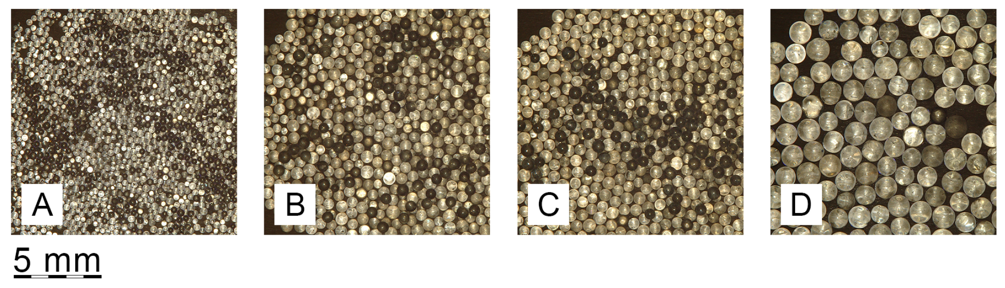
  • Fourth step: When the gripper is in position, the vacuum valve activates. Then, the gripper stands in this position for 40 s. Even though the petrification is almost immediate, the 40 s delay allows the system to reach a steady-state compression force. This compression value reveals the deformation force defined above ( F 2 in Figure 9). Vacuum pressure in our case study (robotic grasping) has an influence on two points: internal influence on the mechanical capabilities of the jamming effect and external influence on the gripper piece contact.
    In the first phenomenon, the higher the vacuum pressure, the more pronounced the jamming effect. This behavior can be qualitatively observed in the results of Hudson [38], where a progression of mechanical performance with increasing vacuum pressure is demonstrated. (Hudson’s results serve here to qualitatively guide the intuition of the effect of pressure, as his work studies the jamming effect only under compression and not under tension, as in our case).
    On the other hand, an increase in vacuum pressure in some prototypes favors an increase in the friction coefficient between the gripper and the grasped piece, as an increase in vacuum pressure causes the internal material to manifest on the external surface of the gripper, increasing its macroroughness (especially in cases of enveloping materials with lower hardness and thinner wall thickness, as shown in Figure 11).
    In any case, in this work, we assume that the effect of increasing vacuum pressure tends towards a limit in which both phenomena saturate. In this study, the research on the influence of pressure is beyond the scope, and we work with a uniform pressure value of 0.8 bar provided by the Venturi device.
  • Fifth step: The setup is ready to start a conventional tensile force test with a 20 mm/min quasi-static speed rate.

4. Results and Discussion
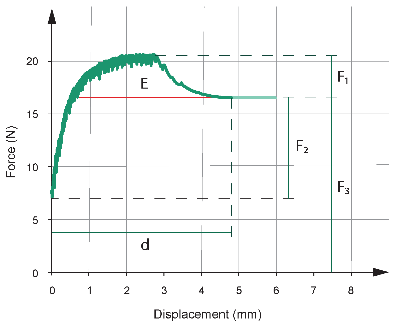
As stated in the Section 3, the tests developed in this work try to optimize three parameters in the pull-off force test. These parameters are lifted weight, stored energy, and deformation force. In a real-world scenario, when the gripper grasps an object, these parameters can translate into the maximum weight the grasped object can be, the energy needed to detach the object from the gripper, and the minimum force required to adapt the gripper to any given shape.
Figure 9 shows the output of a generic pull-off force test. In this figure, the relevant parameters are:
  • Lifted weight ( F 1 ). This parameter corresponds to the peak value in the tensile force curve.
  • Stored energy (E). This parameter is the area between the tensile curve and the final traction value derived from the prototype’s weight ( F 3 ).
  • Deformation force ( F 2 ). This value is equal to the difference between the weight ( F 3 ) and the initial value of the tensile curve.
Figure 9 also shows two other complementary parameters:
  • Gripping distance (d). This parameter shows the distance over which the prototype can grip the mushroom-shaped specimen along its frictional spherical zone (Figure 7A).
  • Total weight of the prototype ( F 3 ). This value includes the weight of the assembly shown in Figure 4 plus other components that attach it to the tensile tester.
As stated in the Section 3, the material combinations result in a four-row by four-column matrix. Every element in the matrix gathers five experiments. Figure 8 shows the outcomes of the pull-off force test in the following arrangement: ball particle diameters increase from left to right, while envelope pliability increases from bottom to top. The three relevant parameters to assess the material combinations emerge from these plots, and the following lines discuss them individually. Figure 12, Figure 13 and Figure 14 show four box-and-whiskers plots each. Each plot corresponds to one complete envelope performance, and they are arranged in such a way that the pliability of the envelopes increases from left to right. Inside every plot, granulate size also increases in the same direction.
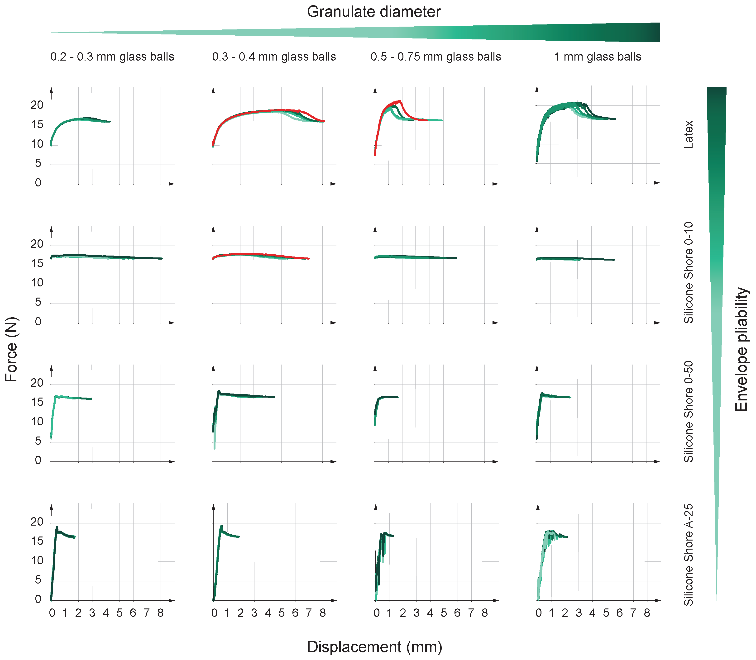
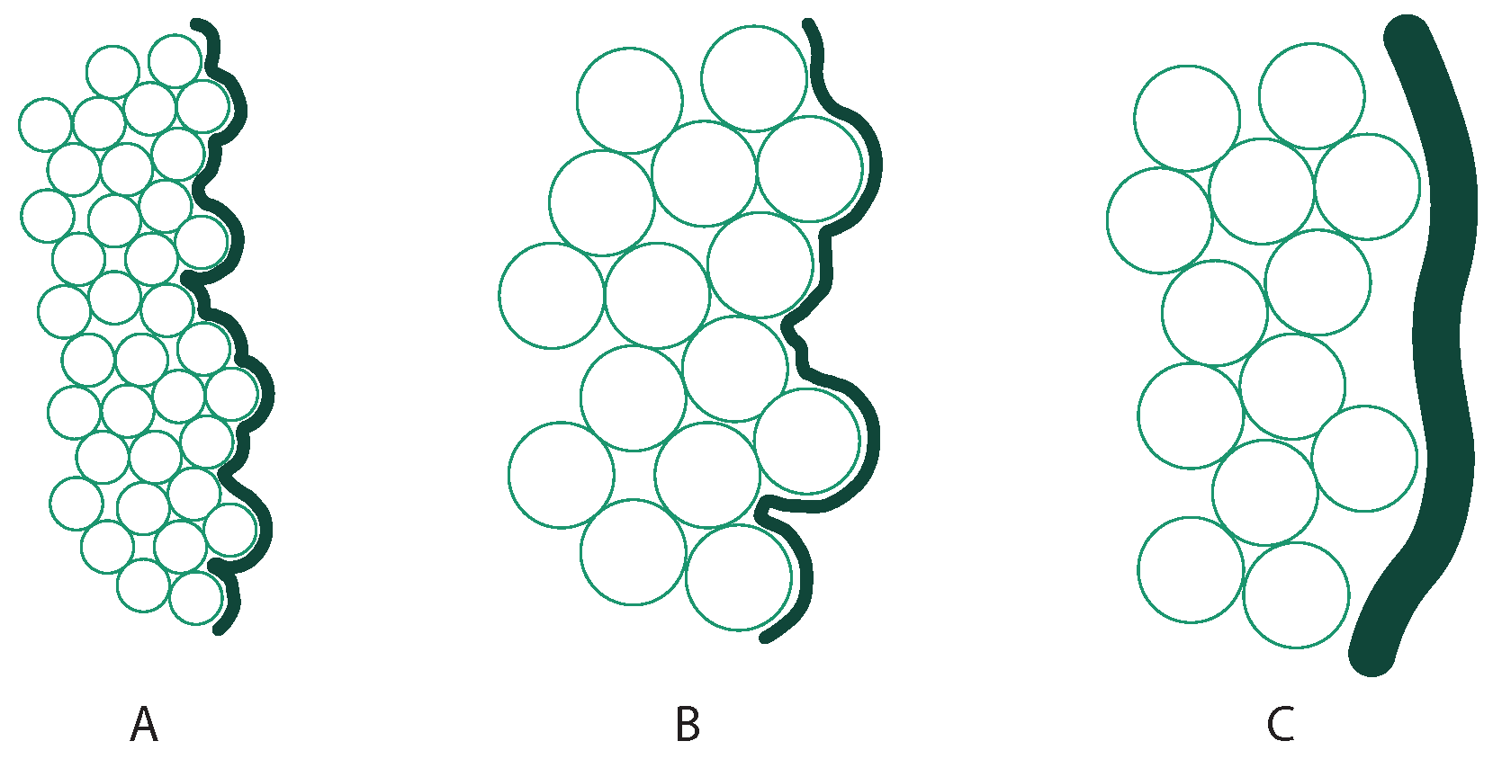
  • Lifted weight: Figure 12 shows the maximum lifted weight results following the guidelines stated above. Here, the three plots on the left (silicones) show the best performance for the 0.3–0.4 mm diameter balls, followed by some pick-up cases for the 1 mm balls.
    Nevertheless, the best behaviors appear with latex (plot on the far right), doubling the best results reached by the silicones. This plot shows a correlation between ball diameter and force output, reaching the best performance with diameters larger than 0.4 mm. Thus, the best combination to optimize the maximum weight the gripper can lift is a latex envelope in addition to the 1.0 mm diameter glass balls (if 0.5–0.75 mm outliers are discarded).
    Figure 12 does not show a clear trend for the influence of the granulate size on the lifted weight, at least in those prototypes manufactured with silicone. However, the opposite happens in the case of the latex envelope. If compared, envelopes are different in the material used to manufacture them but also in their wall thickness (it is relevant to remark here again that these wall thicknesses are the minimum achievable due to manufacturing restrictions; Table 1). Thus, we consider that the main reason the latex shows better results is its wall thickness (0.15 mm). This hypothesis assumes that smaller envelopes’ wall thicknesses allow the relief of the granular material to manifest more easily on the outside. Consequently, different grain sizes allow us to achieve different friction coefficients.
    As indicated in Figure 7A, the lifted weight is due to the frictional force established between the test specimen and the prototype. Thus, this force is directly proportional to the value of the static friction coefficient ( μ ), which can be qualitatively related to the roughness and waviness values of the prototype surface while the prototype is in the jamming phase (vacuum on).
    We performed waviness measurements of the prototypes for different granulate materials. In these measurements, we are only interested in the waviness values (and not in the roughness ones). This bias is because we consider the grain size sufficiently large (from 0.2 to 1.0 mm) to consider its effects on a macroscopic scale. Thus, we discard roughness values, as we consider them to reflect the influence of the envelope surface on a microscopic scale. In addition, since we want to see the influence of the granulate size on performance, it does not make sense to consider any contribution coming from the envelope side.
    The analysis of the prototypes showed minor waviness variations in the silicone cases (wall thicknesses of 1 and 2 mm). This result is due to the thick silicone wall’s cushioning effect, preventing the granular material’s relief from manifesting on the outside (Figure 11, diagram C). However, in the case of latex, significant waviness changes appear when analyzing the different granulate sizes (Figure 11, diagrams A and B) since the latex’s wall thickness is unable to provide any cushioning effect. Table 2 gathers the waviness results for the four different granulate and latex combinations.
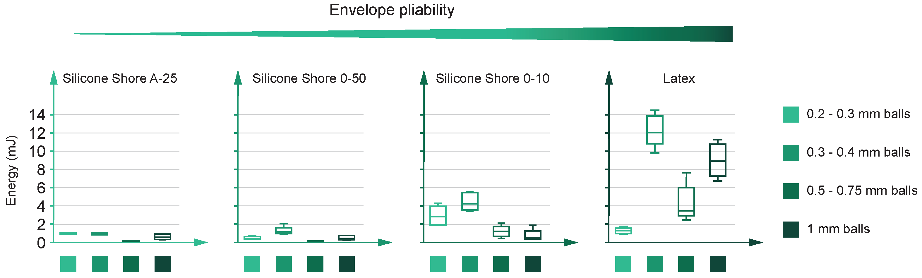
  • Stored energy: Figure 13 shows the energy results of the tests. This figure follows the same format as the previous one. Again, the behavior of the silicones (three plots on the left) differ from the latex and display an inverse correlation between Shore hardness and energy absorption. The two hardest silicones (Shore 00-50 and Shore A-25) find it difficult to reach 2 mJ, but it is relevant to remark on the 0.5–0.75 mm diameter balls’ inability in both scenarios. There, the energy absorption is null.
    On the other hand, still analyzing silicones, the outcomes of the Shore 00-10 silicone improve the results of the hardest ones. The plot shows a properly defined maximum value for the 0.3–0.4 mm diameter one, multiplying by almost three the best results of its competitors.
    Figure 13 shows remarkable differences between silicones when absorbing energy. This difference lies in their plasticity. Analogously, we can refer to tensile tests on metals: more ductile metals obtain higher energy absorption values than brittle ones. Similarly, silicones with lower Shore hardness (more plastic and deformable) obtain better results than those with higher Shore hardness (more rigid).
    Finally, latex shows outstanding behavior compared to silicones. The results improve for every ball diameter, except for the smallest one, and the best combination (0.3–0.4 mm diameter) performs over 10 mJ in almost every case. Finally, it is also interesting that the 1.0 mm diameter balls step up after a sharp drop. This fall is due to the 0.5–0.75 mm balls, which tend to worsen the energy performance for every envelope.
    The simplified energy formula E = F d explains the better latex performance. In this formula, F is the lifted weight, and d is the gripping distance. Here, latex is the envelope that obtains better results because of both parameters: F and d. Lifted weight has already been explained in the previous point, and, on the other hand, latex maximizes the gripping distance d due to its ability to obtain better angle φ values (Figure 7A) and to take advantage of Region A (Figure 7B).
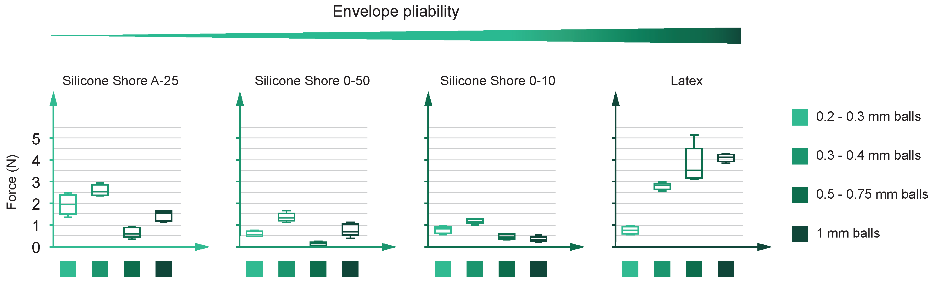
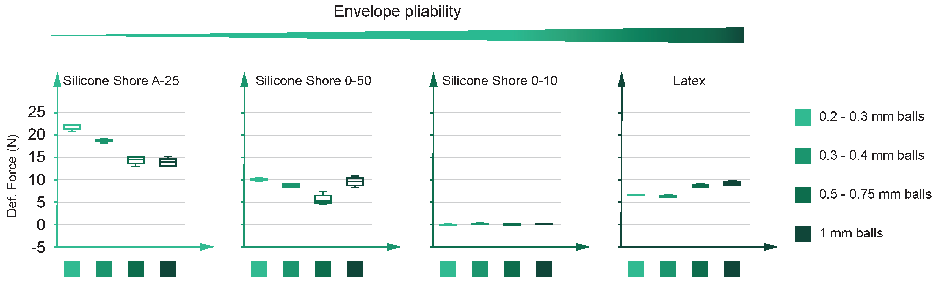
  • Deformation force: Figure 14 shows deformation force results. Again, this figure follows the same format as the previous figures. As stated before, the optimum deformation force is most likely to be the one with the minimum value. The deformation force results allow for breaking off the previously seen silicone cluster, i.e., the silicones produce the best and the worst performance here. The hardest silicone (Shore A-25) suffers the most significant deformation values: in addition to 0.2–0.3 mm balls, the force goes over 20 newtons. Conversely, on the opposite side of the hardness scale, Shore 00-10 silicone results in close to zero forces. In addition, the other materials (latex and Shore 00-50 silicone) show a less attractive behavior, reaching values between 5 to 10 newtons.
    The parameter discussed here shows a clear correlation between the force values and the envelope plasticity. If considered a membrane, the more rigid the envelope is, the more tension appears in the deformation process. This tension restricts the movement of the inner particles, producing higher forces in those cases where the inner particles’ relocation is blocked. Thus, when the envelope adapts its form to the mushroom-shaped part, the glass balls find a limp boundary in the case of Shore 00-10 and a less permissive one in the case of Shore A-25. This difference in the boundary tension leads to particles’ movement behavior and the consequent results in Figure 14.
    Contrary to what happens with the envelope materials, it is not possible to extract a behavior trend for the glass balls. At first glance, the friction force between inner particles might arise as the leading cause contributing to the gripper deformation force. Since friction force is proportional to area, reducing the contact area between balls might be an interesting way to decrease the gripper deformation force. Thus, the larger the glass balls’ diameter, the lower the gripper deformation force. Even though the plot on the right in Figure 14 may confirm this hypothesis, the others discredit it. In this way, the relation between the balls’ diameter and gripper deformation force seems more complex. A new hypothesis might consider the interaction between envelope material and balls (instead of just balls). Thus, the envelopes’ roughness might enter the scene and explain the diameter influence. However, the confirmation of this hypothesis is left for future work.

5. Conclusions

This publication introduces a general guideline for material selection for soft robots in general and universal jamming grippers in particular. We conducted empirical tests for every possible envelope and granulate material combination to obtain this guideline. Both granulate and envelope materials showed a substantial influence on prototype performances: envelope material is critical for obtaining parameters such as the deformation force or the stored energy, while the granulate material size reveals its influence on the prototype’s ability to reach higher lifted weight values.
This last discovery was achieved by testing the latex envelope, an envelope with a wall thickness of just 0.15 mm. Thus, this publication reveals that wall thickness is crucial for optimizing results and allowing granulate materials to reach their potential. Narrow envelope walls allow the waviness provided by the granular material to become visible on the outer surface. Thus, by changing the size of the granules, we can achieve different waviness values and, therefore, different static friction coefficients. In this way, varying the inner material means optimizing the friction force and, consequently, the maximum lifted weight. On the other hand, wide-walled envelopes are insensitive to this effect since they cushion the relief the different grain sizes provide.
Due to these observations, we conclude that latex is the material with higher energy absorption and weight lifting performance. In addition, we remark that latex is not the best envelope for every application; the choice of the material must fulfill the requirements of the specific scenario. Therefore, the hardest silicones still apply when wearing resistance is required (for instance, in tasks with a high number of cycles). On the other hand, softer silicones still have their application niche for grasping fragile objects.
As improvement points, future studies could focus on new manufacturing processes to obtain thinner envelopes (so that any prototype can take advantage of granulate influence on static friction). This research does not consider thickness variation analysis for the same envelope material, but its optimization could enhance results. Furthermore, we also intend to decrease the passivity of the gripper by discretizing its actuation volume. In addition, as future developments, the authors intend to improve the performance of the universal jamming gripper by implementing tactile sense and obtaining feedback and a closed-loop control over its performance.

Supplementary Materials

The following supporting information can be downloaded at: https://www.mdpi.com/article/10.3390/machines12010052/s1. Video S1: The video shows the test process described on the Section 3 in the paper. File S1: The exploded view of the prototype, gathering all elements needed in the assembly.

Author Contributions

Conceptualization, I.d.R., J.B. and A.J.L.-L.; Methodology, I.d.R., J.B. and A.J.L.-L.; Formal analysis, I.d.R., J.B. and A.J.L.-L.; Data curation, I.d.R., J.B. and A.J.L.-L.; Writing—original draft, I.d.R., J.B.; Visualization, I.d.R.; Supervision, A.J.L.-L. All authors have read and agreed to the published version of the manuscript.

Funding

This research received no external funding.

Data Availability Statement

Data are contained within the article.

Acknowledgments

The authors of this publication would like to thank the Chair for Smart Industry for providing the necessary resources to produce this research. In addition, they also acknowledge the contributions of Philip A. Opupele Gavino as a research student. Finally, the authors would like to thank Eva Paz for her recommendations regarding the testing setup.

Conflicts of Interest

The authors declare no conflict of interest.

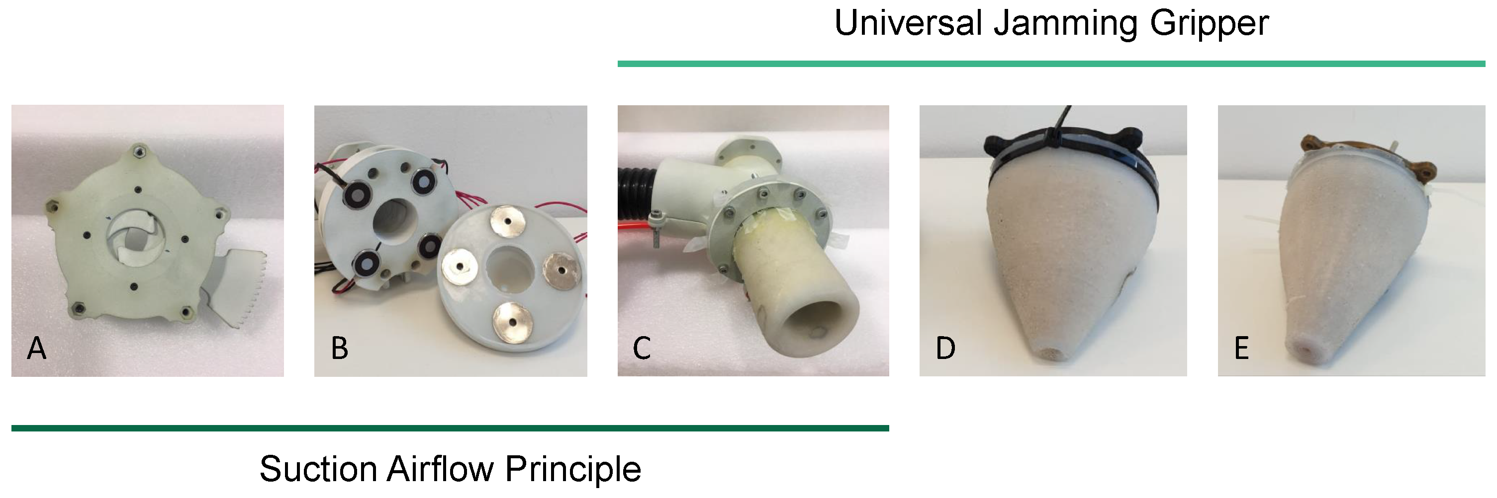
Appendix A. Alternative Gripping Techniques and Decision Matrix

As stated in the paper’s introduction, industry and academia still face a significant problem in automating robotic processes. Chaotic and non-structured scenarios still pose the unsolved question of how to make robots catch parts individually when chaos appears.
To solve this open question, we initially analyzed alternative gripper prototypes prior to the development of this publication and the experiments described in it. We developed a decision matrix to tackle the chaotic scenario issues and included eight different parameters:
  • Complex geometries, flat parts, and soft parts: evaluates the ability of the grippers to grasp parts with these features.
  • Selectivity: describes the ability of the gripper to grasp a unique object in a random and chaotic scene.
  • Active response: indicates if the prototype includes any system to actively react or adapt its behavior depending on the object to grasp.
  • Readiness: describes the ability of the prototype to grasp two completely different objects without requiring intermediate steps, i.e., this indicator punishes those grippers needing an intermediate step to adjust their performance. An intermediate step might be a tool change or any adjustment not done on the fly. On the other hand, this parameter rewards designs with few to no intermediate steps.
  • Sealing: when applicable, this indicator shows the ability of the design to prevent airflow and pressure losses. This parameter often relates to selectivity since air leaks attract an undesired number of objects. Of course, as this factor is not applicable to every prototype, the scores awarded in this section are not computed to choose the final candidate.
  • Compactness: evaluates the ability of the prototype to develop its actions without interfering with other objects surrounding the robot. It also rewards those alternatives with fewer components and mechanisms to trigger the grasping action.
  • Sensorization: describes the potential and predisposition of the prototype to include sensors that might help enrich the system’s data acquisition.
Five different prototypes were tested and analyzed under the chaos criterion, with three based on the suction airflow principle, and the other two on the universal jamming gripper effect. Figure A1 shows the prototypes we explored. Figure A2 shows the analysis’s qualitative results in a decision matrix.
Figure A1. Prototypes. From left to right: mechanical shutter (A), interchangeable nozzles (B), deformable nozzle (C), universal jamming gripper (D), universal jamming gripper with vacuum cup (E).
Machines 12 00052 g0a1
Figure A2. Decision matrix. Each prototype (A–E, as Figure A1 shows) obtains a score according to the capabilities shown. The universal jamming gripper (D) shows the best potential to solve the initial problem: how to grasp one unique part in a chaotic scene with multiple objects.
Machines 12 00052 g0a2
On the one hand, the suction airflow principle makes it possible to manipulate components independently of their geometry. The components are held in place by the pressure difference created by a suction airflow. However, this operation has limitations when operating with different part sizes, as there is a risk of picking up objects when their size is small. We propose three different prototypes based on this approach.
First, we propose a model based on a mechanical shutter (Figure A1A). This model regulates the airflow section by controlling a mechanically driven blade set. In this way, it can narrow or widen the suction section depending on the size of the object to grasp. Despite its good performance when dealing with big objects, this model presents a significant drawback: its selectivity worsens when grasping small parts.
The second alternative we propose is a system of interchangeable magnetic nozzles (Figure A1B). The prototype uses a set of nozzles with different diameters to cover the range of part sizes. The main limitation of this alternative is the need to have as many nozzles as size ranges. Consequently, it is necessary to perform an intermediate step to change the nozzle each time the part size changes.
The last proposal based on suction airflow is a deformable soft robotic nozzle (Figure A1C). In this case, we aim to make the diameter of the nozzle malleable to adapt it to different sizes. Although it reduces the mechanical complexity seen in the mechanical shutter prototype, the soft nozzle, as the second alternative, requires an intermediate step to deform its shape. In addition, its deformation abilities do not prevent the prototype from struggling to enhance the selectivity shown by the shutter prototype.
On the other hand, the second method to grasp objects is a soft robotic-based solution: the universal jamming gripper. This design seeks to manipulate components using a deformable body that adapts its geometry to the shape of the components to grasp.
First, we explore the original universal jamming gripper solution: a cone-shaped gripper made of a highly malleable material filled with different granulates (Figure A1D). We describe its behavior in the publication.
Finally, the last proposal is similar to the previous one but incorporates a vacuum cup system looking for a hybrid solution (Figure A1E). However, this modification reduces the system’s deformation capacity, worsening the gripper’s ability to grasp parts using the jamming effect.
As shown in Figure A2, the best prototype is the universal jamming gripper with a final score of 17 points, followed by the mechanical shutter, the interchangeable nozzles, and the universal jamming gripper with vacuum cup (16 points for each of them; remember that sealing points are not computable in the final score and are only valid to distinguish between airflow prototypes). Finally, the least appealing prototype, the deformable and soft robotic nozzle, reaches 15 points.

References

  1. Eppner, C.; Höfer, S.; Jonschkowski, R.; MartÍn-Martín, R.; Sieverling, A.; Wall, V.; Brock, O. Lessons from the amazon picking challenge: Four aspects of building robotic systems. In Robotics: Science And Systems; Springer: Cham, Switzerland, 2016. [Google Scholar]
  2. Correll, N.; Bekris, K.E.; Berenson, D.; Brock, O.; Causo, A.; Hauser, K.; Okada, K.; Rodriguez, A.; Romano, J.M.; Wurman, P.R. Analysis and observations from the first amazon picking challenge. IEEE Trans. Autom. Sci. Eng. 2016, 15, 172–188. [Google Scholar] [CrossRef]
  3. Yang, Y.; Vella, K.; Holmes, D.P. Grasping with kirigami shells. Sci. Robot. 2021, 6, eabd6426. [Google Scholar] [CrossRef] [PubMed]
  4. Gu, S.; Holly, E.; Lillicrap, T.; Levine, S. Deep reinforcement learning for robotic manipulation with asynchronous off-policy updates. In Proceedings of the 2017 IEEE International Conference on Robotics and Automation (ICRA), Singapore, 29 May–3 June 2017; pp. 3389–3396. [Google Scholar]
  5. Redmon, J.; Divvala, S.; Girshick, R.; Farhadi, A. You only look once: Unified, real-time object detection. In Proceedings of the IEEE Conference on Computer Vision and Pattern Recognition, Las Vegas, NV, USA, 26 June–1 July 2016; pp. 779–788. [Google Scholar]
  6. He, K.; Gkioxari, G.; Dollár, P.; Girshick, R. Mask r-cnn. In Proceedings of the IEEE International Conference on Computer Vision, Venice, Italy, 22–29 October 2017; pp. 2961–2969. [Google Scholar]
  7. Yan, B.; Fan, P.; Lei, X.; Liu, Z.; Yang, F. A real-time apple targets detection method for picking robot based on improved YOLOv5. Remote. Sens. 2021, 13, 1619. [Google Scholar] [CrossRef]
  8. Chen, K.; Cao, R.; James, S.; Li, Y.; Liu, Y.H.; Abbeel, P.; Dou, Q. Sim-to-Real 6D Object Pose Estimation via Iterative Self-training for Robotic Bin-picking. arXiv 2022, arXiv:2204.07049. [Google Scholar]
  9. Mahler, J.; Matl, M.; Satish, V.; Danielczuk, M.; DeRose, B.; McKinley, S.; Goldberg, K. Learning ambidextrous robot grasping policies. Sci. Robot. 2019, 4, eaau4984. [Google Scholar] [CrossRef]
  10. Cartucho, J.; Tukra, S.; Li, Y.S.; Elson, D.; Giannarou, S. VisionBlender: A tool to efficiently generate computer vision datasets for robotic surgery. Comput. Methods Biomech. Biomed. Eng. Imaging Vis. 2021, 9, 331–338. [Google Scholar] [CrossRef]
  11. Kitagawa, S.; Wada, K.; Hasegawa, S.; Okada, K.; Inaba, M. Few-experiential learning system of robotic picking task with selective dual-arm grasping. Adv. Robot. 2020, 34, 1171–1189. [Google Scholar] [CrossRef]
  12. Todorov, E.; Erez, T.; Tassa, Y. Mujoco: A physics engine for model-based control. In Proceedings of the 2012 IEEE/RSJ International Conference on Intelligent Robots and Systems, Loulé, Portugal, 7–12 October 2012; pp. 5026–5033. [Google Scholar]
  13. Levine, S.; Pastor, P.; Krizhevsky, A.; Ibarz, J.; Quillen, D. Learning hand-eye coordination for robotic grasping with deep learning and large-scale data collection. Int. J. Robot. Res. 2018, 37, 421–436. [Google Scholar] [CrossRef]
  14. Xiong, Y.; Ge, Y.; From, P.J. An obstacle separation method for robotic picking of fruits in clusters. Comput. Electron. Agric. 2020, 175, 105397. [Google Scholar] [CrossRef]
  15. Gafur, N.; Kanagalingam, G.; Ruskowski, M. Dynamic collision avoidance for multiple robotic manipulators based on a non-cooperative multi-agent game. arXiv 2021, arXiv:2103.00583. [Google Scholar]
  16. Shintake, J.; Cacucciolo, V.; Floreano, D.; Shea, H. Soft robotic grippers. Adv. Mater. 2018, 30, 1707035. [Google Scholar] [CrossRef] [PubMed]
  17. Kim, S.; Laschi, C.; Trimmer, B. Soft robotics: A bioinspired evolution in robotics. Trends Biotechnol. 2013, 31, 287–294. [Google Scholar] [CrossRef] [PubMed]
  18. Elsayed, Y.; Vincensi, A.; Lekakou, C.; Geng, T.; Saaj, C.; Ranzani, T.; Cianchetti, M.; Menciassi, A. Finite element analysis and design optimization of a pneumatically actuating silicone module for robotic surgery applications. Soft Robot. 2014, 1, 255–262. [Google Scholar] [CrossRef]
  19. Luo, Y.; Wu, K.; Spielberg, A.; Foshey, M.; Rus, D.; Palacios, T.; Matusik, W. Digital Fabrication of Pneumatic Actuators with Integrated Sensing by Machine Knitting. In Proceedings of the CHI Conference on Human Factors in Computing Systems, New Orleans, LA, USA, 29 April–5 May 2022; pp. 1–13. [Google Scholar]
  20. Li, S.; Stampfli, J.J.; Xu, H.J.; Malkin, E.; Diaz, E.V.; Rus, D.; Wood, R.J. A vacuum-driven origami “magic-ball” soft gripper. In Proceedings of the 2019 International Conference on Robotics and Automation (ICRA), Montreal, QC, Canada, 20–24 May 2019; pp. 7401–7408. [Google Scholar]
  21. Coulson, R.; Stabile, C.J.; Turner, K.T.; Majidi, C. Versatile soft robot gripper enabled by stiffness and adhesion tuning via thermoplastic composite. Soft Robot. 2021, 9, 189–200. [Google Scholar] [CrossRef]
  22. Fantoni, G.; Capiferri, S.; Tilli, J. Method for supporting the selection of robot grippers. Procedia CIRP 2014, 21, 330–335. [Google Scholar] [CrossRef]
  23. Brown, E.; Rodenberg, N.; Amend, J.; Mozeika, A.; Steltz, E.; Zakin, M.; Lipson, H.; Jaeger, H. Universal robotic gripper based on the jamming of granular material. Proc. Natl. Acad. Sci. USA 2010, 107, 18809–18814. [Google Scholar] [CrossRef]
  24. Lambeta, M.; Chou, P.W.; Tian, S.; Yang, B.; Maloon, B.; Most, V.R.; Stroud, D.; Santos, R.; Byagowi, A.; Kammerer, G.; et al. DIGIT: A novel design for a low-cost compact high-resolution tactile sensor with application to in-hand manipulation. IEEE Robot. Autom. Lett. 2020, 5, 3838–3845. [Google Scholar] [CrossRef]
  25. Follmer, S.; Leithinger, D.; Olwal, A.; Cheng, N.; Ishii, H. Jamming user interfaces: Programmable particle stiffness and sensing for malleable and shape-changing devices. In Proceedings of the 25th Annual ACM Symposium on User Interface Software and Technology, Cambridge, MA, USA, 7–10 October 2012; pp. 519–528. [Google Scholar]
  26. Jaeger, H.M. Celebrating soft matter’s 10th anniversary: Toward jamming by design. Soft Matter 2015, 11, 12–27. [Google Scholar] [CrossRef]
  27. Dierichs, K.; Menges, A. Designing architectural materials: From granular form to functional granular material. Bioinspiration Biomimetics 2021, 16, 065010. [Google Scholar] [CrossRef]
  28. Fitzgerald, S.G.; Delaney, G.W.; Howard, D. A review of jamming actuation in soft robotics. Actuators 2020, 9, 104. [Google Scholar] [CrossRef]
  29. Amend, J.R.; Brown, E.; Rodenberg, N.; Jaeger, H.M.; Lipson, H. A positive pressure universal gripper based on the jamming of granular material. IEEE Trans. Robot. 2012, 28, 341–350. [Google Scholar] [CrossRef]
  30. Amend, J.; Cheng, N.; Fakhouri, S.; Culley, B. Soft robotics commercialization: Jamming grippers from research to product. Soft Robot. 2016, 3, 213–222. [Google Scholar] [CrossRef]
  31. Choi, Y.T.; Hartzell, C.M.; Leps, T.; Wereley, N.M. Gripping characteristics of an electromagnetically activated magnetorheological fluid-based gripper. AIP Adv. 2018, 8, 056701. [Google Scholar] [CrossRef]
  32. Nishida, T.; Okatani, Y.; Tadakuma, K. Development of universal robot gripper using MR α fluid. Int. J. Humanoid Robot. 2016, 13, 1650017. [Google Scholar] [CrossRef]
  33. Li, Y.; Chen, Y.; Yang, Y.; Wei, Y. Passive particle jamming and its stiffening of soft robotic grippers. IEEE Trans. Robot. 2017, 33, 446–455. [Google Scholar] [CrossRef]
  34. Bartkowski, P.; Gawiński, F.; Pawliszak, Ł. E-Morph as a New Adaptive Actuator for Soft Robotics. IEEE Robot. Autom. Lett. 2022, 7, 8831–8836. [Google Scholar] [CrossRef]
  35. Götz, H.; Santarossa, A.; Sack, A.; Pöschel, T.; Müller, P. Soft particles reinforce robotic grippers: Robotic grippers based on granular jamming of soft particles. Granul. Matter 2022, 24, 31. [Google Scholar] [CrossRef]
  36. Loeve, A.J.; van de Ven, O.S.; Vogel, J.G.; Breedveld, P.; Dankelman, J. Vacuum packed particles as flexible endoscope guides with controllable rigidity. Granul. Matter 2010, 12, 543–554. [Google Scholar] [CrossRef]
  37. Miskin, M.Z.; Jaeger, H.M. Evolving design rules for the inverse granular packing problem. Soft Matter 2014, 10, 3708–3715. [Google Scholar] [CrossRef]
  38. Hudson, S.W. Mechanical Characterization of Jammable Granular Systems. Ph.D. Thesis, Massachusetts Institute of Technology, Cambridge, MA, USA, 2012. [Google Scholar]
  39. Howard, D.; O’Connor, J.; Letchford, J.; Brett, J.; Joseph, T.; Lin, S.; Furby, D.; Delaney, G.W. Getting a Grip: In Materio Evolution of Membrane Morphology for Soft Robotic Jamming Grippers. In Proceedings of the 2022 IEEE 5th International Conference on Soft Robotics (RoboSoft), Edinburgh, UK, 4–8 April 2022; pp. 531–538. [Google Scholar]
  40. Jiang, A.; Ranzani, T.; Gerboni, G.; Lekstutyte, L.; Althoefer, K.; Dasgupta, P.; Nanayakkara, T. Robotic granular jamming: Does the membrane matter? Soft Robot. 2014, 1, 192–201. [Google Scholar] [CrossRef]
  41. Xiao, W.; Du, X.; Chen, W.; Yang, G.; Hu, D.; Han, X. Cooperative collapse of helical structure enables the actuation of twisting pneumatic artificial muscle. Int. J. Mech. Sci. 2021, 201, 106483. [Google Scholar] [CrossRef]
  42. Wei, Y.; Chen, Y.; Ren, T.; Chen, Q.; Yan, C.; Yang, Y.; Li, Y. A novel, variable stiffness robotic gripper based on integrated soft actuating and particle jamming. Soft Robot. 2016, 3, 134–143. [Google Scholar] [CrossRef]
  43. Cheng, N.G.; Lobovsky, M.B.; Keating, S.J.; Setapen, A.M.; Gero, K.I.; Hosoi, A.E.; Iagnemma, K.D. Design and analysis of a robust, low-cost, highly articulated manipulator enabled by jamming of granular media. In Proceedings of the 2012 IEEE International Conference on Robotics and Automation, St. Paul, MN, USA, 14–18 May 2012; pp. 4328–4333. [Google Scholar]
  44. Licht, S.; Collins, E.; Mendes, M.L.; Baxter, C. Stronger at depth: Jamming grippers as deep sea sampling tools. Soft Robot. 2017, 4, 305–316. [Google Scholar] [CrossRef] [PubMed]
  45. Cheng, N.; Amend, J.; Farrell, T.; Latour, D.; Martinez, C.; Johansson, J.; McNicoll, A.; Wartenberg, M.; Naseef, S.; Hanson, W.; et al. Prosthetic jamming terminal device: A case study of untethered soft robotics. Soft Robot. 2016, 3, 205–212. [Google Scholar] [CrossRef]
  46. Jiang, Y.; Amend, J.R.; Lipson, H.; Saxena, A. Learning hardware agnostic grasps for a universal jamming gripper. In Proceedings of the 2012 IEEE International Conference on Robotics and Automation, St. Paul, MN, USA, 14–18 May 2012; pp. 2385–2391. [Google Scholar]
  47. Hermes, M.; Dijkstra, M. Jamming of polydisperse hard spheres: The effect of kinetic arrest. Europhys. Lett. 2010, 89, 38005. [Google Scholar] [CrossRef]
Figure 1. Chaotic samples. Challenging scenarios for robots with different degrees of entropy: unstable arrangement (A), vertical overlap (B), and coplanar overlap (C).
Machines 12 00052 g001
Figure 3. Granulate dimensions. From (AD): 0.2–0.3 mm, 0.3–0.4 mm, 0.5–0.75 mm, 1.0 mm. All images taken at 20× zoom magnification.
Machines 12 00052 g003
Figure 4. Gripper assembly. Subassembly A is the rigid body anchoring the gripper and encasing the vacuum filter. Subassembly B is the soft body described in this publication. We provide further details about the entire assembly in the Supplementary Materials section.
Machines 12 00052 g004
Figure 5. The prototype’s grasping principles. According to Amend et al. [29], physical phenomena that allow a universal jamming gripper (black contours) to pick up parts (green contours) include: static friction by deriving friction forces (A), geometric constraints by allowing for the application of normal forces (B), or vacuum chambers by producing pressure differences (C).
Machines 12 00052 g005
Figure 6. Setup components: (A) tensile force tester, (B) mushroom-shaped test specimen, (C) gripper, (D) force sensor, (E) moving end of the tensile force tester, (F) vacuum line, (G) Venturi device, (H) compressor.
Machines 12 00052 g006
Figure 7. Mushroom-shaped test specimen. Interaction between gripper and test part specimen. (A) Definition of specimen design parameters. (B) Section drawing showing the interaction between gripper and specimen at the maximum compression position. (C) Comparison between the initial and final positions of the gripper after the pull-off test; between the two positions, deformation of the gripper occurs while the jamming effect manifests.
Machines 12 00052 g007
Figure 8. Pull-off force test raw results. The four–row by four–column matrix gathers the results from the prototypes’ pull-off force tests. Every column corresponds to a different granulate size, while every row corresponds to a different envelope material. Granulate size increases from left to right. Envelope pliability improves from bottom to top. Every element in the matrix represents a material combination test. We tested every prototype five times: each test corresponds to a different green curve. By coloring them in red, we highlight those tests reaching an optimum value (lifted weight, stored energy, or deformation force).
Machines 12 00052 g008
Figure 9. Generic pull-off force test plot. The force versus displacement plot provides all parameters describing the behavior of the prototypes. The traction curve (dark green color) increases until it reaches the maximum value. From that point, the force decreases until it stabilizes. A residual tensile force becomes apparent at this point (the gripper weight, represented by light green). The relevant parameters are the lifted weight ( F 1 ), the stored energy (E), and the deformation force ( F 2 ). Two other complementary parameters are the distance the gripper manages to grip the mushroom-shaped specimen (d) and the total weight of the prototype ( F 3 ).
Machines 12 00052 g009
Figure 10. Generic compression plot. Compression force versus tester moving part displacement. During the compression phase and before the pull-off force test, the prototypes behave differently depending on their abilities to collapse. Thus, those combinations of granulate material plus an envelope with proper fluidity and pliability are likely to behave like the light green curve (curve A), while the less fluid granulates and less pliable envelopes tend to behave like the dark green one (curve B). In order to set a standard procedure, we avoided the non-linear compression region and compressed every prototype until the tester moving part reached 45 mm from the zero position (Figure 7A).
Machines 12 00052 g010
Figure 11. Consequences on friction performance due to granulate–envelope interaction. Different combinations of materials produce a different response in surface waviness. Thus, the material combination’s ability to provide a higher or lower level of waviness conditions the friction force that prototypes can exert. Latex is the envelope that allows a higher level of waviness (A,B). The presence of bigger granulate materials emphasizes this behavior. On the other hand, when the envelope material is silicone ((C), with wider walls due to manufacturing constraints, Table 1), the influence of the interior material is hidden (due to the ability of the wide silicone walls to pad the granular effect).
Machines 12 00052 g011
Figure 12. Lifted weight results. Four charts summarize the results of the lifted weight. Each chart corresponds to a different envelope material, with increasing pliability from left to right. Each chart shows maximum force versus granulate size in the form of a box–and–whisker plot. Within each plot, the granule size also increases from left to right.
Machines 12 00052 g012
Figure 13. Stored energy results. Four charts summarize the stored energy results. Each chart corresponds to a different envelope material, with increasing pliability from left to right. Each chart shows energy versus granulate size in the form of a box–and–whisker plot. Within each plot, the granule size also increases from left to right.
Machines 12 00052 g013
Figure 14. Deformation results. Four charts summarize the deformation force results. Each chart corresponds to a different envelope material, with increasing pliability from left to right. Each chart shows deformation force versus granulate size in the form of a box–and–whisker plot. Within each plot, the granule size also increases from left to right.
Machines 12 00052 g014
Table 1. Envelope properties: density, wall thickness, and roughness for every tested envelope.
S. A-25S. 00-50S. 00-10Latex
Density [g cm3]1.181.071.040.96
Thickness [mm]1.02.02.00.15
Roughness [μm]6.1529.0115.2632.06
Table 2. Latex prototype waviness for the different granulate materials. Waviness values obtained with a cut-off value ( λ ) equal to 0.8 mm.
0.2–0.3 mm0.3–0.4 mm0.5–0.75 mm1.0 mm
Waviness [μm]9.5428.8123.5574.86
Disclaimer/Publisher’s Note: The statements, opinions and data contained in all publications are solely those of the individual author(s) and contributor(s) and not of MDPI and/or the editor(s). MDPI and/or the editor(s) disclaim responsibility for any injury to people or property resulting from any ideas, methods, instructions or products referred to in the content.

