Abstract
Due to the effects of swing motion, the performances and internal flow characteristics of marine centrifugal pump undergo some unsteady variations in the marine environment. The hydraulic test system with six degree of freedom parallel motion platform is established to study the pump performance characteristics at the different heel angles of steady roll position and pitch position. The pump head gradually decreases as heel angle increases. The pump head has decreased by 7% to reach the minimum at the 15° heel angle of roll position. At the same heel angle, the head at the roll position is lower than that at the pitch position under the rated flow condition. The fluid in the impeller passage is subjected to the additional inertial force of roll motion or pitch motion under unsteady swing motion, inducing some flow bias phenomena in the velocity field. The unsteady development of flow velocity induces the intense vortex motion, and the shedding and dissipation of interblade vortices are affected. The periodic flow-induced pulsation characteristics obviously appear in the impeller passage. The pulsation periodicity and pressure amplitude are influenced due to the swing motion. The pitch motion induces the greater hydraulic excitation and fluid-induced vibration amplitude. In addition to the pressure pulsation at the low frequencies, the pulsation amplitude at 20 times the shaft frequency is evident under pitch motion.
1. Introduction
The marine centrifugal pump is the core device in the key marine systems such as marine liquid supply system and cooling system, which increases the kinetic and pressure energy of the flow fluid in the system. The pump may experience some unsteady phenomena such as internal flow disorder and flow excitation during operation in the ocean environment, which can affect the stable operation of the pump. The swing motion in the ocean environment increases the extra inertial force exerted on the fluid particles and has the negative effects on the pump’s hydrodynamic characteristics, resulting in the significant decrease in the pump head and efficiency.
The interaction of ocean waves and winds superimposes some movements on the ship, inducing some additional forces on the flow inside the shipboard fluid machinery. These movements include roll, pitch, heel, surge, sway, and heave in six degrees of freedom. Thereinto, several movements are neglected because magnitudes of surge, sway, and heave are small owing to the finite geometry of the machinery [1,2]. The effects of roll and pitch have been extensively studied, especially for fluid machinery. Roll motion gives rise to the variation in the gravity and generates other acceleration components causing the periodic fluctuations in the flow field and flow-induced vibration, which can modify the flow characteristics and operation stability significantly [3,4,5]. The average mass flow rate and viscosity loss in the fluid machinery under roll motion are affected by the roll frequency and amplitude. The frictional pressure drop fluctuates with the period of roll motion and its amplitude is raised with the average Reynolds number of inner flow increasing [6,7,8], which induces the pressure performance degradation of marine pump. The transient variations in the friction coefficients and pressure fluctuations in the flow caused by roll motion are found to be quite different from steady-state approximations and cannot be predicted by the steady flow and energy transfer correlations [9,10]. Then, some experiment correlations are provided to simulate the approximation of transient variations in the friction coefficient due to the roll condition. Obvious fluctuation features appear in the flow development induced by roll motion [11,12,13]. As for the fluid machinery with a symmetrical structure, the mathematical treatment of rolling and pitching is similar [14,15,16]. However, the centrifugal pump has an asymmetric volute structure and is subject to different effects of roll and pitch motion. The flow characteristics and pump performances under the effect of the pitch motion are studied for various pitch angles and periods. An apparent hump curve exists in the head characteristics due to the pitch motion. The flow becomes increasingly turbulent as the pitch period shortens, and the fluid-induced pressure periodic variation presents the parabolic feature [17,18].
The flow characteristics in the marine pump undergo the sudden variation due to the unsteady swing motion. The additional inertial force of swing motion changes the flow velocity and acceleration of fluid particles, thereby altering the vortex dynamic characteristics. However, the unsteady evolution of vortex structures can affect flow characteristics in the pump [19,20,21]. The blade placement angle needs to be matched with the inflow angle to reduce the hydraulic losses caused by impeller inflow impact. When the pump works under the swing condition, the inflow deviates from the blade placement angle, forming the impact flow at the impeller-inlet field [22,23,24]. As a result, it is easy to induce some vortices to drive some unsteady flows, including flow separation, flow stall, and secondary flow [25,26,27]. These vortices move and dissipate towards the impeller outlet as the blades rotate. The evolutions of the inlet vortex, stall vortex, and wake vortex share the same dominant frequency components [28,29]. The typical jet-wake flow occurs when the fluid leaves the impeller. The non-uniform velocity distribution at the impeller outlet interferes with the flow inside the volute, resulting in the complex flow impact and energy transformation phenomena. The vortex structure flowing out of the blade passage undergoes the dissipation and mixing, inducing the pulsation characteristics at the different frequencies to affect the steady operation of the pump [30,31,32]. The swing motion makes the stator-rotor interaction more complex.
As reviewed above, previous studies on flow characteristics under the swing motion are based on the assumption that the mathematical simulations for roll and pitch are similar. However, for the centrifugal pump with an asymmetric volute structure, different influences of roll and pitch will affect on the flow characteristics and pump performances. Some research on the contribution of pitch motion to the pump performances has been conducted in our preliminary work [17,18]. This paper establishes a hydraulic test system with the six degree of freedom parallel motion platform to test and analyze the pump performances at the heel position. Large eddy simulation is employed to obtain and explore the vortex dynamic characteristics and unsteady flow features to study the relationship between vortex evolution and swing motion. This work provides some evidences in the optimization design and improved operation stability of the marine centrifugal pump to have the engineering significance and academic value in the high-tech ship design.
2. Materials and Methods
2.1. Marine Centrifugal Pump Model
A centrifugal pump in the marine liquid supply system is chosen as the research object in this paper. The rated condition of the model pump is operated at the Reynolds number of 1.1 × 10⁵, while the pump head and impeller rotation speed are 16 m and 2900 r/min, respectively. The pump structure consists of a single-stage centrifugal impeller and a spiral volute. The centrifugal impeller is used to increase the kinetic and pressure energy of the water, while the volute is applied to converting the kinetic energy into the pressure energy based on a series of cross-sections with the increasing cross-section area. The precise geometric specifications of the model pump are listed in Table 1.

Table 1.
Design requirements of centrifugal pump.
2.2. Experimental Devices and Methods
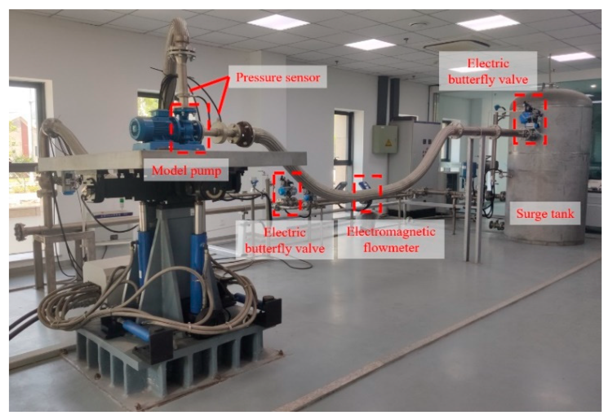
A hydraulic test system with the six-dof (degree of freedom) parallel motion platform is set up to investigate the effects of swing motion on pump performance characteristics in the marine environment. The test platform is made up of a model pump, six-dof parallel motion platform, electric butterfly valve, surge tank, and pipelines, as illustrated in the Figure 1. The pump performance test system with an electromagnetic flowmeter, torque speed sensor, and pressure sensor, is used to capture and gather the tested data. The circulating water is supplied by the surge tank and enters the model pump suction. The electric butterfly valve is set at the water supply pipe of the surge tank to control the flow rate of the hydraulic test system. Pressure sensors are installed in the pipelines connecting the model pump, spaced two pipe diameters apart from the pump inlet or outlet. The ring pressure chamber is used to gain the steady pressures of pump inlet and outlet pipelines. The test data are monitored and recorded by the electromagnetic flowmeter installed in the pump outlet pipeline. The upstream and downstream pipeline lengths of the flowmeter are longer than ten times of the pipe diameter.
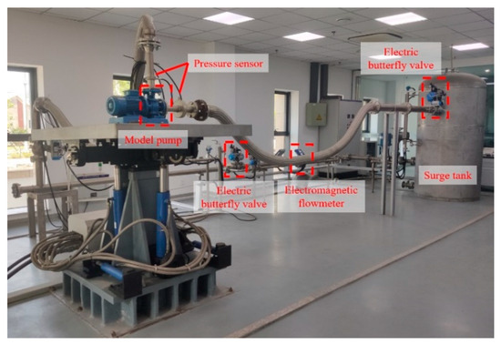
Figure 1.
Centrifugal pump hydraulic test platform with six-dof parallel motion platform.
The head coefficient (ψ), hydraulic efficiency (η), and static pressure coefficient (CP) are introduced to evaluate the performance characteristics of model pump, as shown in Equations (1)–(3).
where PT, ρ, U2, QP, T, and ω are the total pressure, water density, blade tip velocity, pump flow rate, torque, and impeller angular velocity, respectively. The subscripts 2, in, and out indicate the impeller outlet, measuring locations at the pump inlet and outlet, respectively.
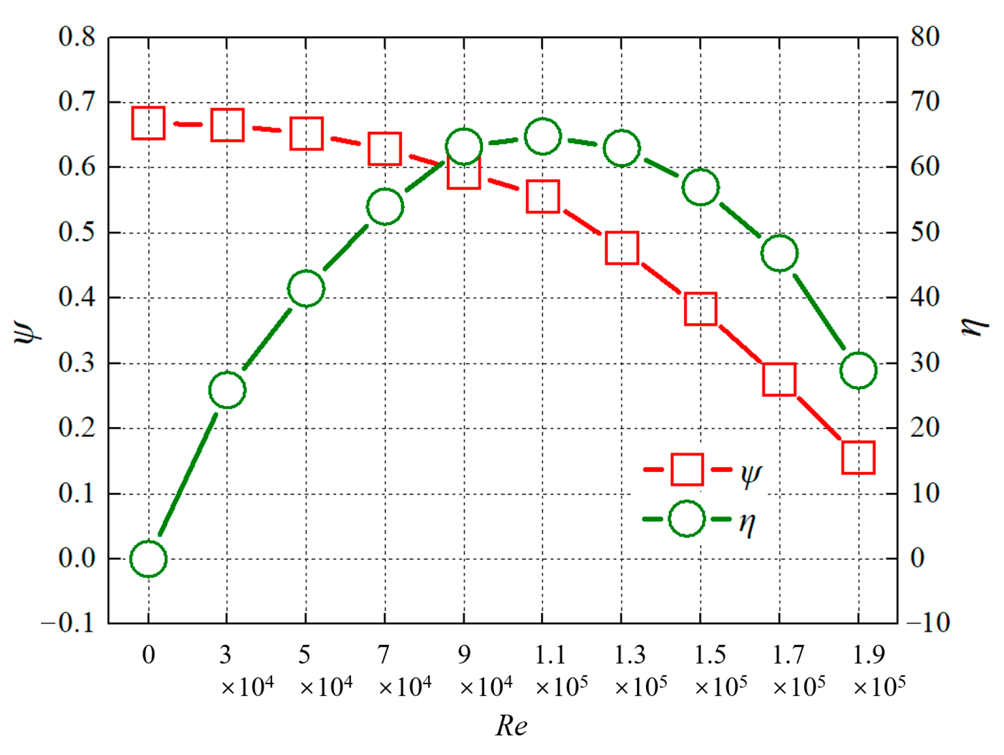
When the pump operating environment is at the static state, the head coefficient decreases gradually with the increase of the Reynolds number (Re) in Equation (4). Meanwhile, the hydraulic efficiency experiences a process of first increasing and then decreasing. A peak exists in the efficiency curve, and it is the rated operating efficiency for the model pump. The Reynolds number at this efficiency peak is 1.1 × 10⁵, as exhibited in the Figure 2.
where V, D, and υ are flow velocity in the inlet pipe, inlet pipe diameter, and kinematic viscosity, respectively.
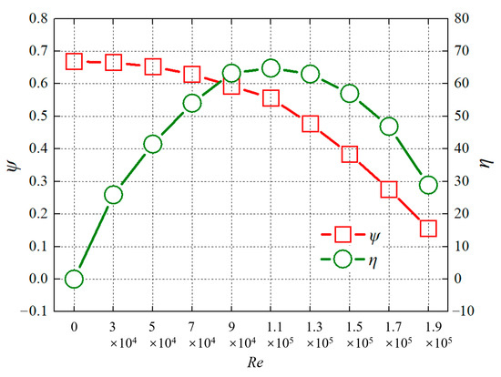
Figure 2.
Pump performance characteristics under the static state.
2.3. Numerical Simulation Method
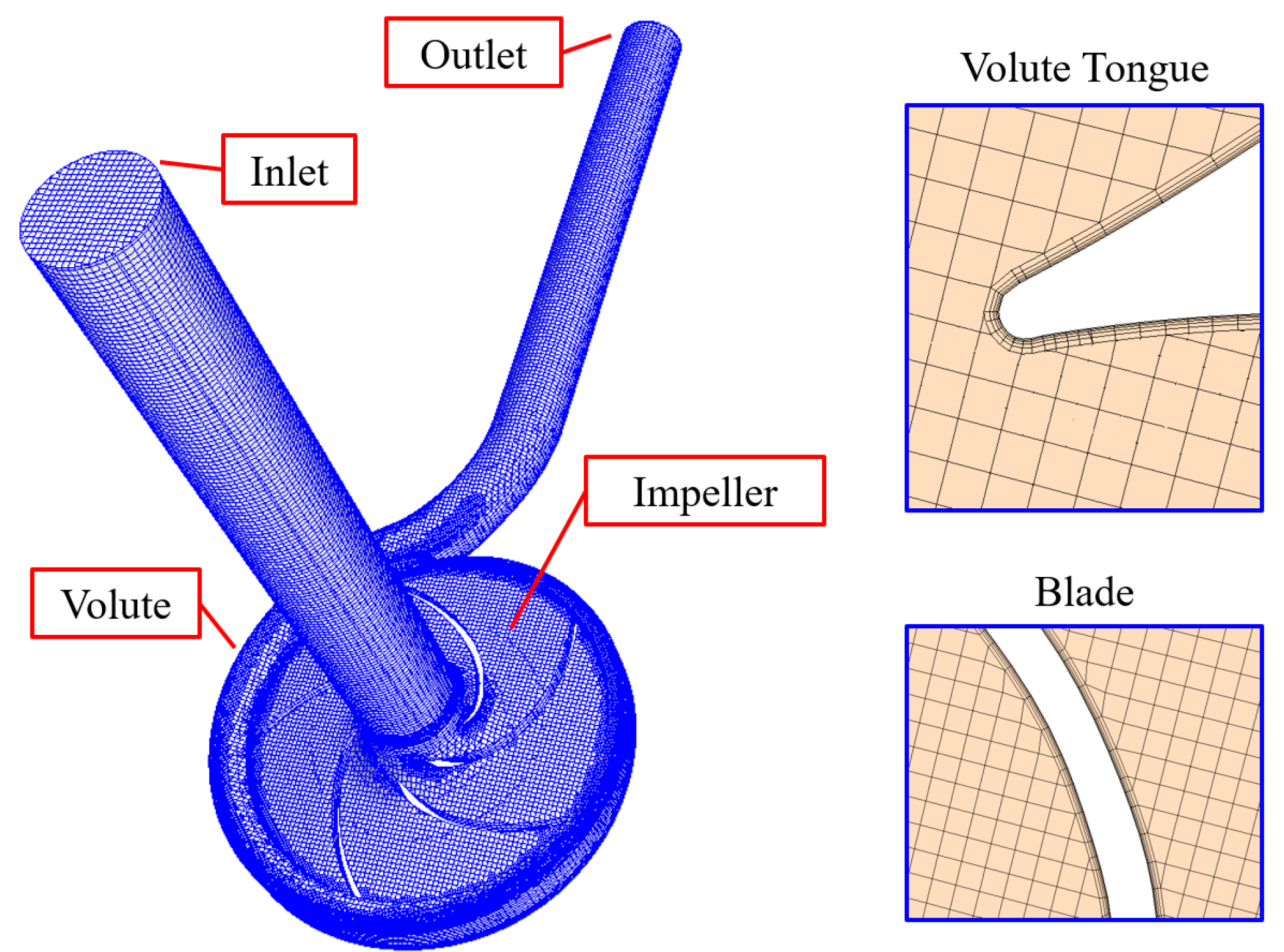
The pump performance characteristics and inner flow features of the model pump under the swing motion are obtained based on numerical simulations. The computational domain of the model pump is composed of the pump inlet, impeller passage, volute chamber, and outlet extension. The hexahedral mesh is applied to each independent domain in Figure 3. Non-dimensional wall distances Δx+ and Δz+ in the impeller domain are less than 10, while Δy+ is less than 2. The maximum non-dimensional wall distance y+ value is less than 1. For the pump inlet and volute chamber, Δx+ and Δz+ are less than 25. The maximum non-dimensional wall distance y+ value is less than 1. Finer grids are devoted to the computational domain after performing the grid independence test using the grid convergence index (GCI). The GCI is defined in Equation (5), and this grid GCI test on account of the ψ values at the rated pump flow is displayed in Table 2. The mesh with 1.2 × 10⁷ grid points is selected in this work, considering the computing capacity and grid error.
where is the safety factor ranging from 1.25 to 3.00, is the mesh refinement ratio, and is the relative error between grids.

Figure 3.
Computation domains and grids.
Table 2.
Grid independence analysis.
The numerical simulation method for the model pump operation under swaying motion is established on the pisoFoam solver of OpenFOAM (v12) platform. The multiple reference coordinate system with a swaying coordinate system is established to realize pump simulations under the swaying motion. The simulation solution for the inner flow characteristics of the model pump is based on the large eddy model. Equations (6) and (7) present the momentum conservation equation and the mass conservation equation under the instantaneous state by the filter function. The Smagorinsky model is employed to solve the flow problems in the vortex motion by Equations (8)–(11). The shear-modified eddy viscosity model is adopted to meet the requirements of the vortex motion on the wall surface, considering the strong shear near the wall. The original eddy viscosity coefficient is changed to the new eddy viscosity coefficient in Equations (10) and (11).
where , , , represents the network size along the i axis.
where , , , , .
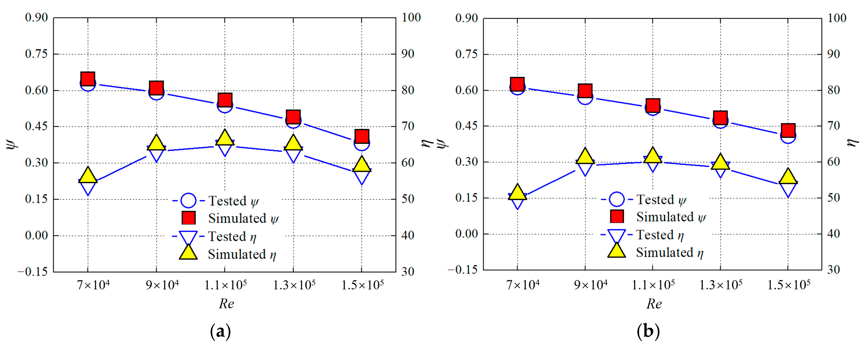
In the numerical simulation method, the inlet boundary is set to “velocity” with the accurate velocity component of the model pump operation condition, while the outlet boundary condition is set to “outlet” with the experimentally determined pressure of the pump outlet. The 1 degree impeller rotation is selected as the time step, the duration time is the length of the impeller rotating eight revolutions due to the steady internal flow characteristics. The comparison of simulated pump performance characteristics and experimental data is exhibited in Figure 4, including the static-state condition, roll motion with roll angle of 15 degrees, and roll period of 5 s. The simulated ψ and η are less than 2.5% and 3.8% of the experimental results at the pump rated flow, respectively. The simulation error in the static-state condition is more uniform, while the error in the roll motion fluctuates. This illustrates that the simulation error under the swing motion is uncertain, but it is in good agreement with the experimental data. Obviously, the simulated result is a little higher than the experimental data, which is attributed to the hydraulic loss and mechanical loss in the model pump.
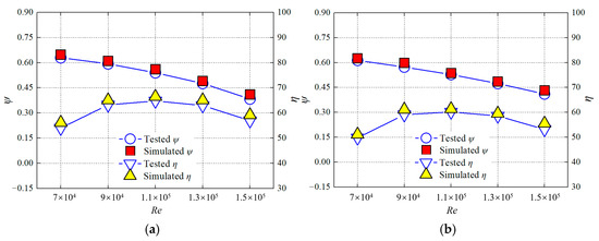
Figure 4.
Comparison between simulated and tested performance characteristics: (a) static state, (b) 15° roll.
3. Result and Discussion
3.1. Steady Pump Performances at the Heel Position
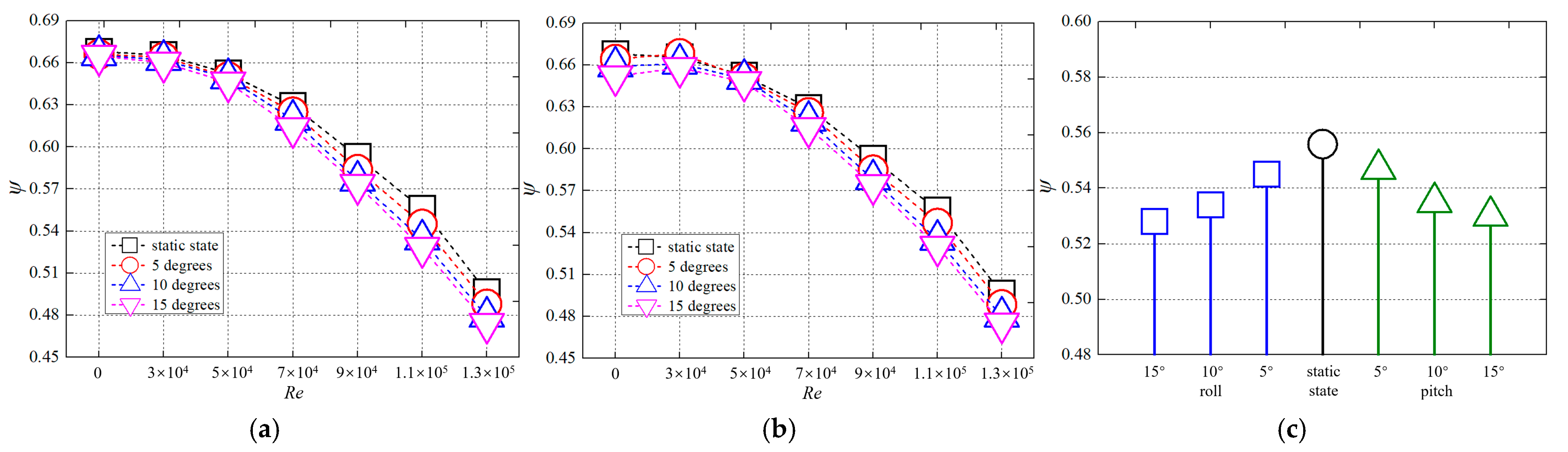
The marine environment can cause ship systems to be under the transient swing motion or at a certain heel position for a period of time. The roll motion is considered to be a left-right swing motion centered on the pipeline axis, while the pitch motion is defined as the pump inlet and outlet pipes swinging up and down with the pump. When the pump is operating at a particular heel position, some water flow motion parameters, such as inflow angle and outflow angle, will vary, leading to significant declines in the pump performance characteristics. Figure 5 displays the test performance characteristics of model pump at the roll positions and pitch positions. The pump ψ gradually decreases as the heel angle of roll position increases, while the same situation occurs at the pitch condition. The ψ value is significantly smaller at the 15° roll position and 15° pitch position, compared to the static environment and other angular positions. This phenomenon indicates a decrease in pump performance when the pump is tilted, illustrating that the inner loss of the pump has increased and the flow becomes more chaotic. The ψ decrease difference increases consistently as the Re increases at the roll position [33,34]. However, the hump ψ curve appears in the small flow-rate condition at the pitch position, and the hump variation is more obvious as the pitch angle increases. The pitch causes the change in the impact angle of the pump inlet water, increasing the hydraulic loss, especially in the small flow-rate condition, which is particularly significant in the ψ decrease in these conditions.
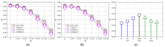
Figure 5.
Steady pump performances at the swing position: (a) roll position, (b) pitch position, (c) under the rated Re condition.
As for the rated Re condition when the marine pump is normally operated, the increasing heel angle has a negative effect on the pump performances, as shown in Figure 5c. The pump head gradually decreases, as the heel angle increases. The ψ has decreased by 7% to reach the minimum at the 15° heel angle of roll position. At the same heel angle, the head of the pump at the roll position is lower than that at the pitch position, which indicates that the roll environment has a more significant impact on the pump performances [17,35].
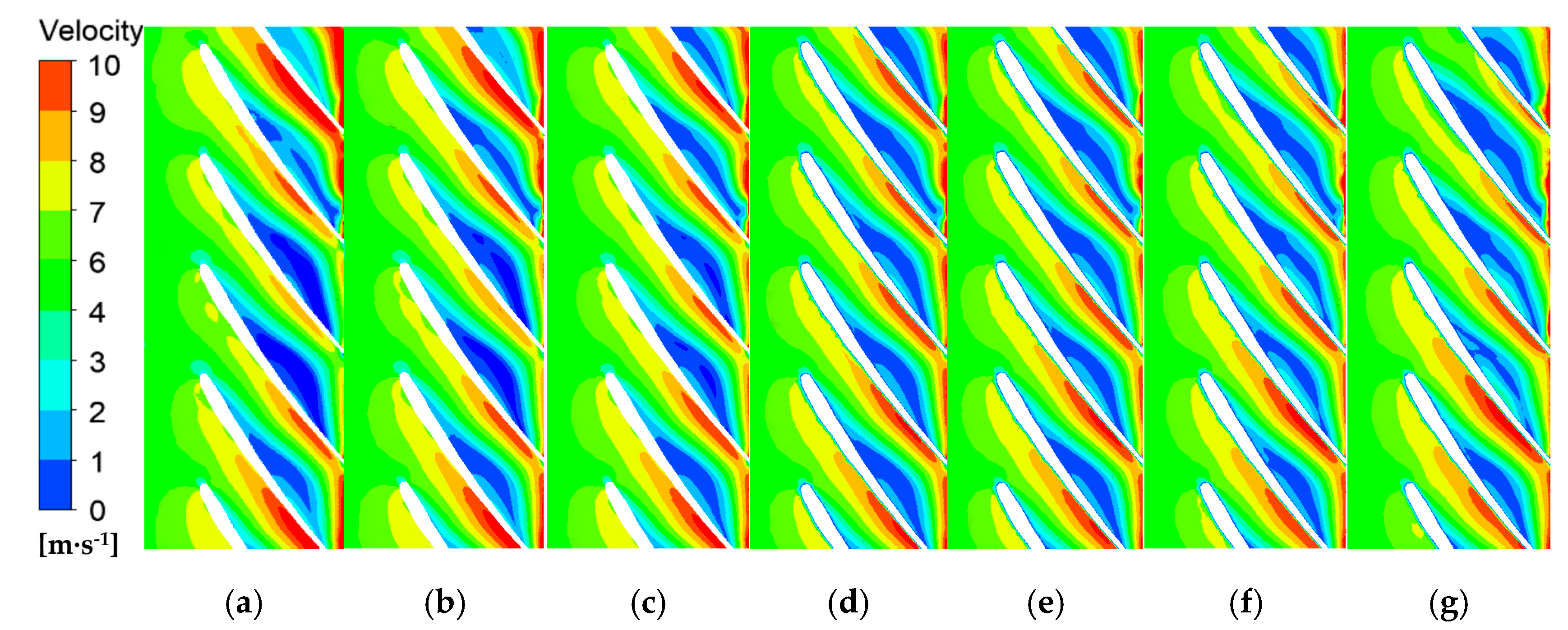
The decline in pump performance is caused by the internal turbulent flow [25]. Figure 6 provides the unsteady flow characteristics in the impeller passage at the horizontal position and heel positions. Figure 6d shows the uniform increase in flow velocity. High-speed fluid appears at the blade tail, while low-velocity fluid clusters on the suction surface of the blade. Uneven flow distribution occurs in the impeller passage at the heel position. When the pump is placed at the pitch position, there is a marked variation in the high-speed flow area on the blade pressure surface and the low-speed flow area on the blade suction surface. The low-speed flow area on the blade suction surface decreases, while the high-speed flow area on the blade pressure surface increases. The development of the pressure difference between blade pressure surface and blade suction surface increases the blade load, which generates the obvious hydraulic excitation. This phenomenon increasingly becomes apparent as the pitch angle increases from Figure 6e to Figure 6g. However, at the roll position, the high-speed fluid mainly concentrates in two or three blade passages, while the low-speed fluid appears in other blade passages. Part of the blades perform useful work on the fluid, leading to a decrease in the pump performance. This non-uniform flow distribution in the impeller passage becomes evident from Figure 6a to Figure 6c.
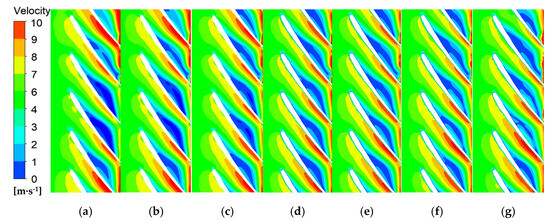
Figure 6.
Flow structures in the impeller under different motions: (a) 15° roll position, (b) 10° roll position, (c) 5° roll position, (d) horizontal position, (e) 5° pitch position, (f) 10° pitch position, (g) 15° pitch position.
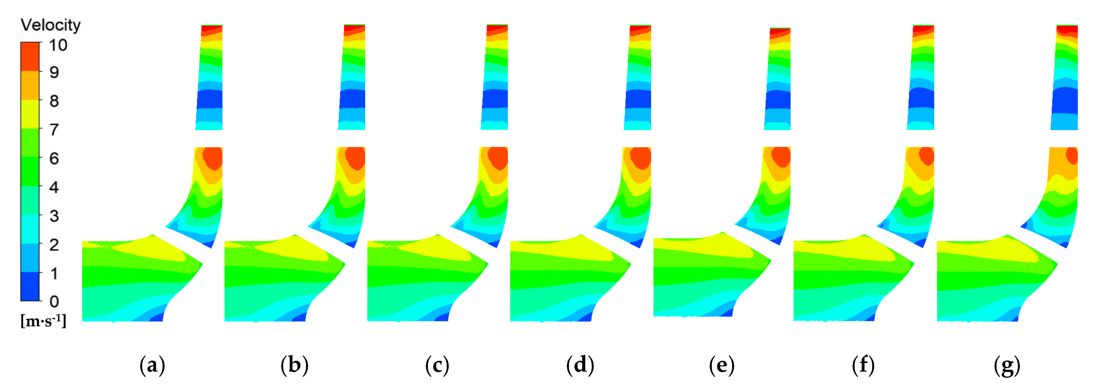
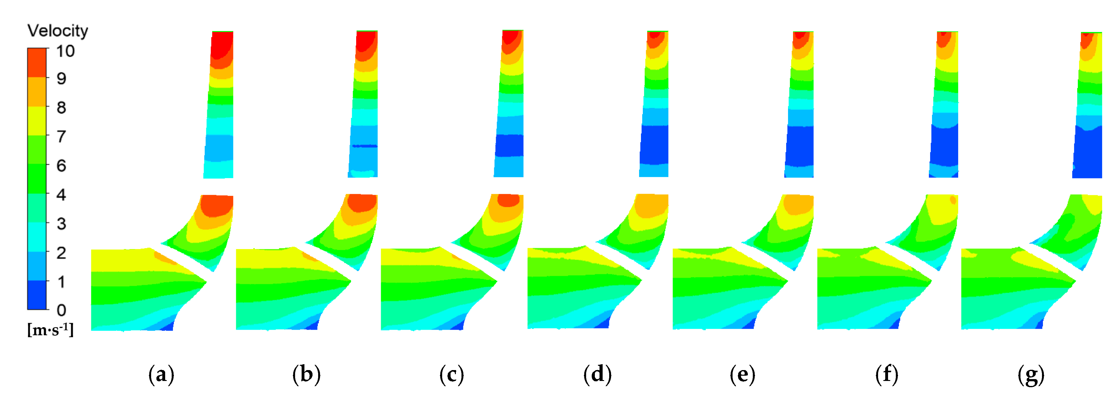
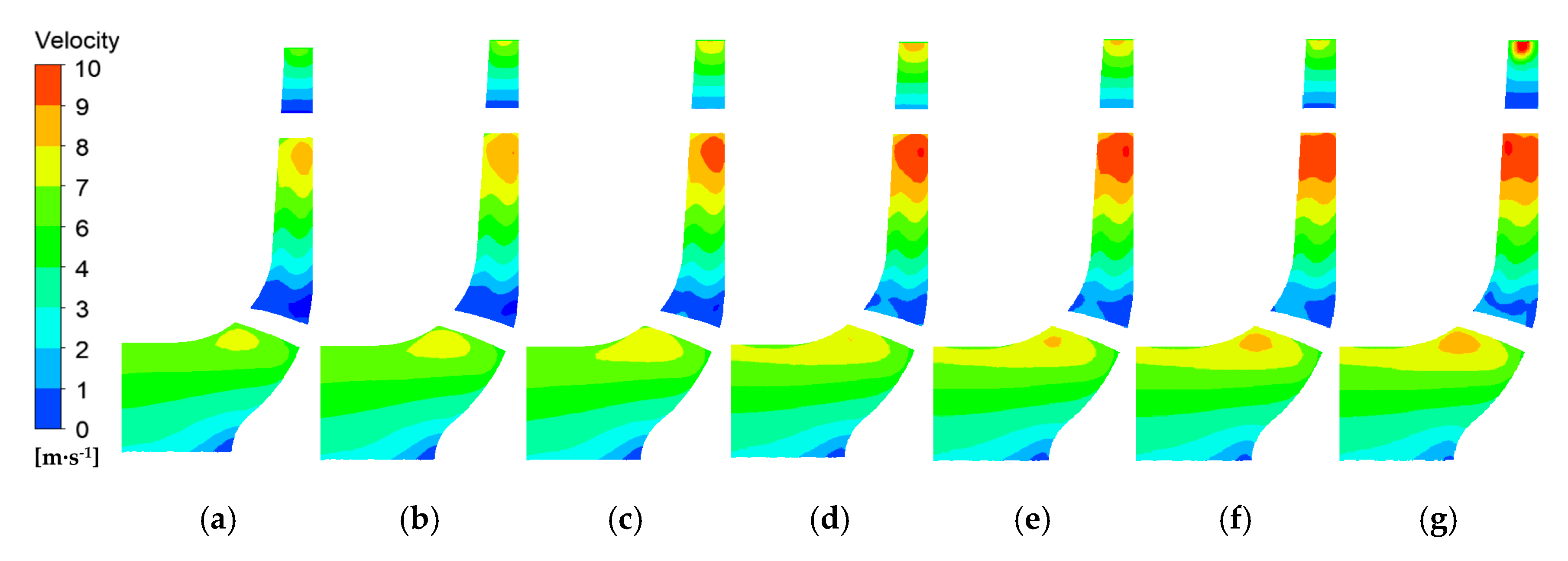
The heel position not only causes uneven flow distribution in the impeller radial section in Figure 6, but also induces the flow bias in the impeller axial section. Four sections were selected to investigate the unsteady flow variation in the impeller radial section at the heel position in Figure 7. The velocity distributions along the radial flow passage are shown from Figure 8, Figure 9, Figure 10 and Figure 11. The high-speed fluid at the vertical impeller section is affected by the pitch position in Figure 8 and Figure 10, high-speed fluid at the vertical impeller section is affected by the pitch position. The high-speed flow area in the blade middle at the 1# impeller section decreases with the pitch angle increase, while that in the blade tail at the 3# section increases. As for the horizontal section, both the roll and pitch have a certain impact on the development of the flow inside the impeller, but the effect of the roll is more significant as shown in Figure 9 and Figure 11. Based on the unsteady flow in the impeller mentioned above, it can be seen that the flow turbulence mainly occurs near the blades, indicating that the heel position affects the energy transfer of the blade to the fluid. The flow velocity and direction change under the inertia force at the swing position, impacting the work of fluid particle on the blade and the momentum conversion of fluid particle [36,37].
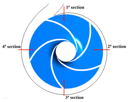
Figure 7.
Selected impeller axial section.
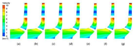
Figure 8.
Flow distribution in 1# impeller section: (a) 15° roll position, (b) 10° roll position, (c) 5° roll position, (d) horizontal position, (e) 5° pitch position, (f) 10° pitch position, (g) 15° pitch position.
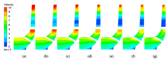
Figure 9.
Flow distribution in 2# impeller section: (a) 15° roll position, (b) 10° roll position, (c) 5° roll position, (d) horizontal position, (e) 5° pitch position, (f) 10° pitch position, (g) 15° pitch position.
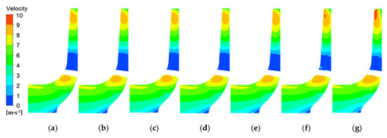
Figure 10.
Flow distribution in 3# impeller section: (a) 15° roll position, (b) 10° roll position, (c) 5° roll position, (d) horizontal position, (e) 5° pitch position, (f) 10° pitch position, (g) 15° pitch position.
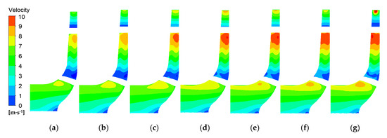
Figure 11.
Flow distribution in 4# impeller section: (a) 15° roll position, (b) 10° roll position, (c) 5° roll position, (d) horizontal position, (e) 5° pitch position, (f) 10° pitch position, (g) 15° pitch position.
3.2. Transient Flow Characteristics under the Swing Motion
Due to the influence of the marine environment, the marine pump has been operating under transient swing motion. The transient swing angle is introduced to analyze the influences of roll and pitch on inner flow characteristics, defined as θ(x) in Equation (12).
where θmax is the maximum swing angle, including 5 degrees, 10 degrees, and 15 degrees. k is the swing period, 5 s.
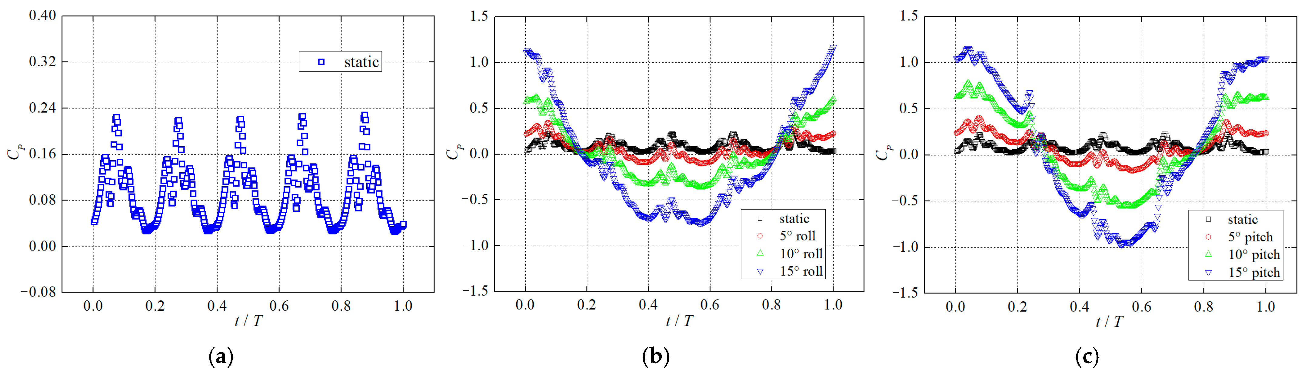
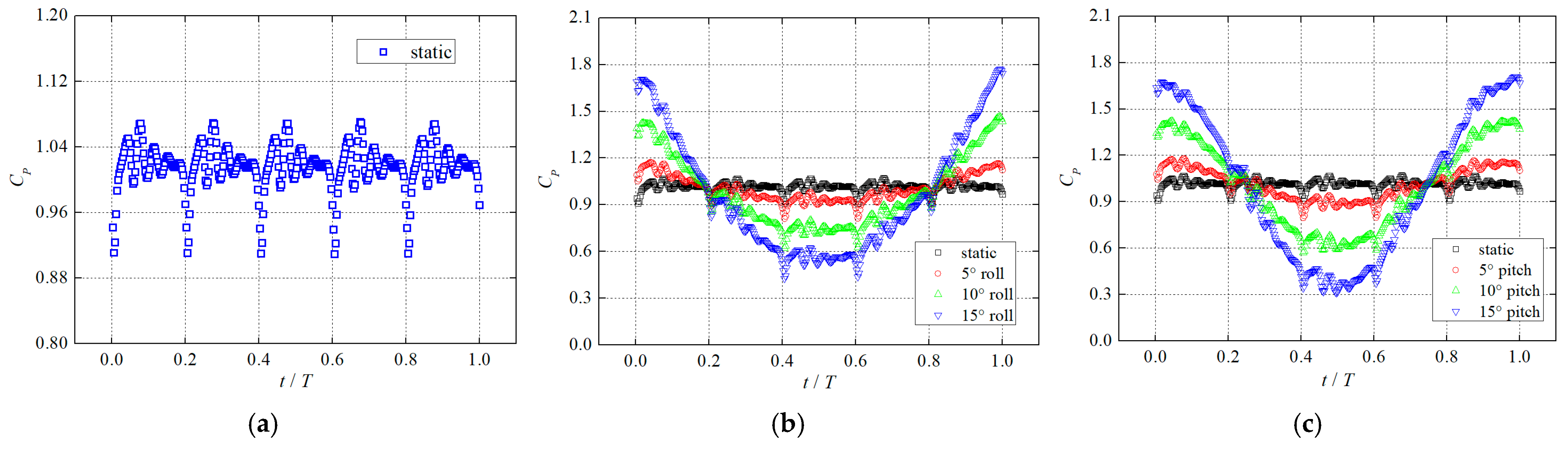
The periodic pressure pulsation characteristics obviously appear in the impeller inlet at the static position in Figure 12a. The five-blade impeller structure causes the interaction between the water from the inlet pipe and impeller flow, resulting in the five cycles of hydraulic excitation features [28,29]. The swing motion has a significant impact on the pressure development features, as seen in Figure 12b,c, changing the periodicity of the original pressure pulsation and the extreme values of pressure peak and pressure valley. The increased swing inertia force of the swing motion alters the energy conversion of the water flow in the pump. When the centrifugal inertia force inside the impeller is in the same direction to the swing inertia force, it increases the force acting on the fluid particle, and the amplitude of the flow induced pressure enhances. On the contrary, the amplitude of pressure pulsation decreases and emerges at the valley. Analogously, periodic pressure development exists at the impeller outlet in Figure 13a, caused by the interaction between the periodic flow inside the impeller and volute tongue. Especially within one cycle, there is an oscillation characteristic of increase and decrease for the pressure amplitude. The flow structure of the jet-wake at the impeller outlet induces unsteady pressure characteristics. The swing motion increases the amplitude variation between the peak and valley of pulsation pressure at the impeller outlet in Figure 13b,c. Notably, the amplitude difference caused by pitch motion is bigger than that by roll motion, which indicates that the pitch motion pitch induces greater fluid induced vibration due to unsteady hydraulic excitation.
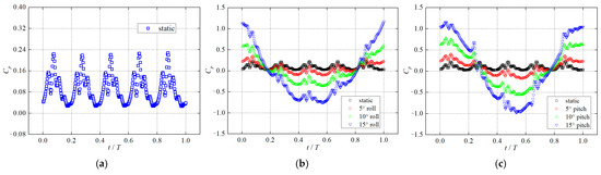
Figure 12.
Time-variant pressure characteristics in the impeller inlet: (a) static position, (b) roll motion, (c) pitch motion.
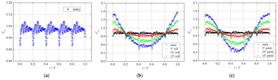
Figure 13.
Time-variant pressure characteristics in the impeller outlet: (a) static position, (b) roll motion, (c) pitch motion.
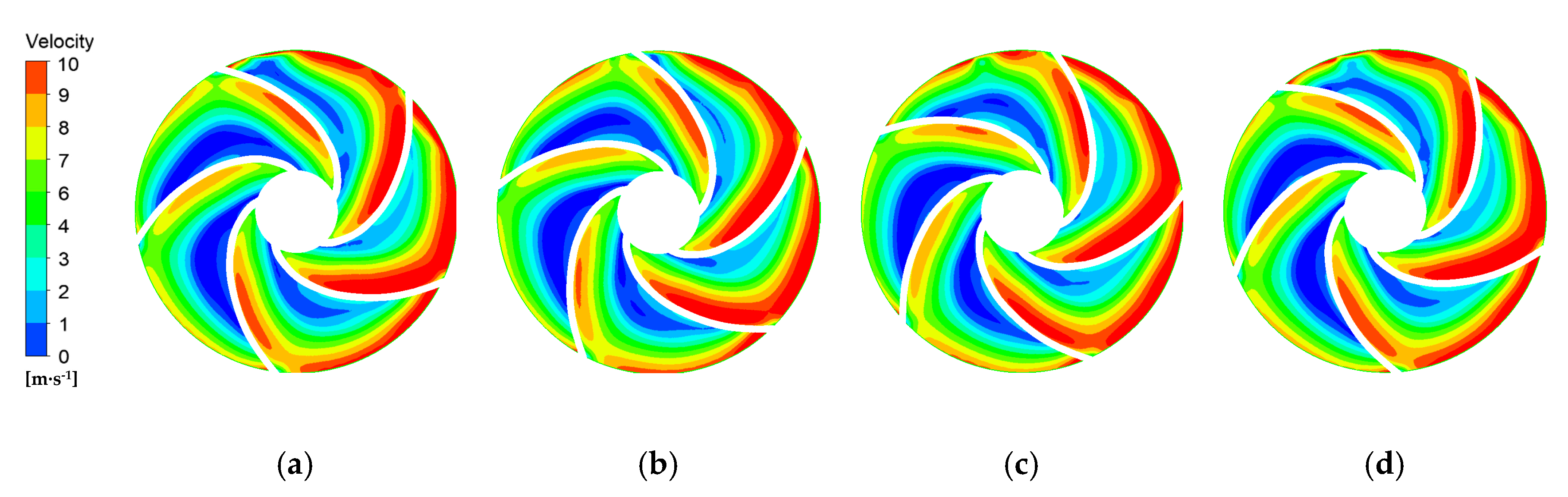
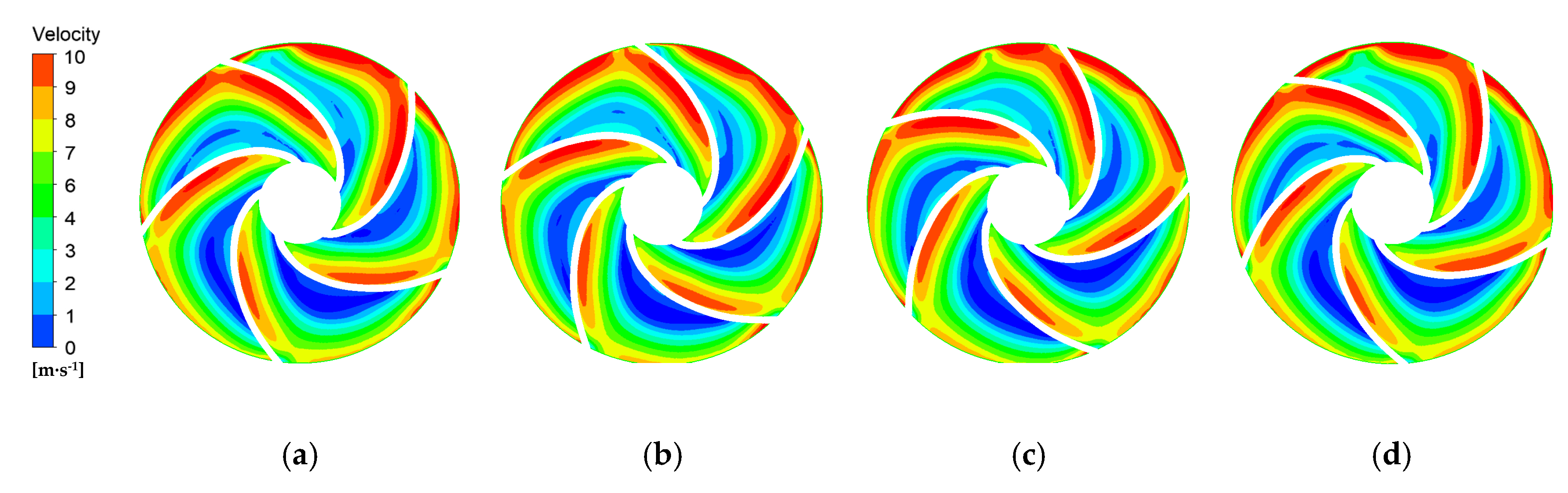
Figure 14 displays the flow characteristics in the impeller passage under the static position during one blade rotation period (Tb). When the centrifugal pump is installed in the static position, the flow distributions in the five blade passages are relatively similar. The blades perform work on the fluid, and the fluid velocity gradually increases. The dynamic fluid at the impeller outlet interferes with the annular moving fluid inside the volute, resulting in the flow separation of the high-speed fluid from the impeller [30,31]. When the pump is in an upward roll on the right side, as shown in Figure 15, the fluid in the right side of impeller passage is subjected to the inertial force of roll motion. The transport velocity of the fluid in the right passage increases, leading to an increase in the absolute velocity of the fluid. The uneven distribution of the fluid kinetic energy in the flow passages on both sides of the impeller can cause a decrease in the pump performance. When the pump pitches upwards, as shown in Figure 16, the flow in the upper passage of the impeller is significantly affected and the flow velocity increases. Moreover, the volute tongue is located at the upper part of the impeller outlet, which exacerbates the stator-rotor interaction between the impeller and the tongue, inducing intense fluid-induced vibration.
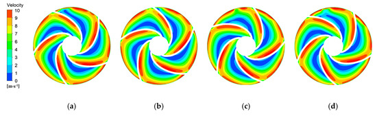
Figure 14.
Impeller flow characteristics within one blade rotation cycle under the static position: (a) Tb/4, (b) Tb/2, (c) 3Tb/4, (d) Tb.

Figure 15.
Impeller flow characteristics within one blade rotation cycle under the roll motion: (a) Tb/4, (b) Tb/2, (c) 3Tb/4, (d) Tb.
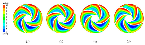
Figure 16.
Impeller flow characteristics within one blade rotation cycle under the pitch motion: (a) Tb/4, (b) Tb/2, (c) 3Tb/4, (d) Tb.
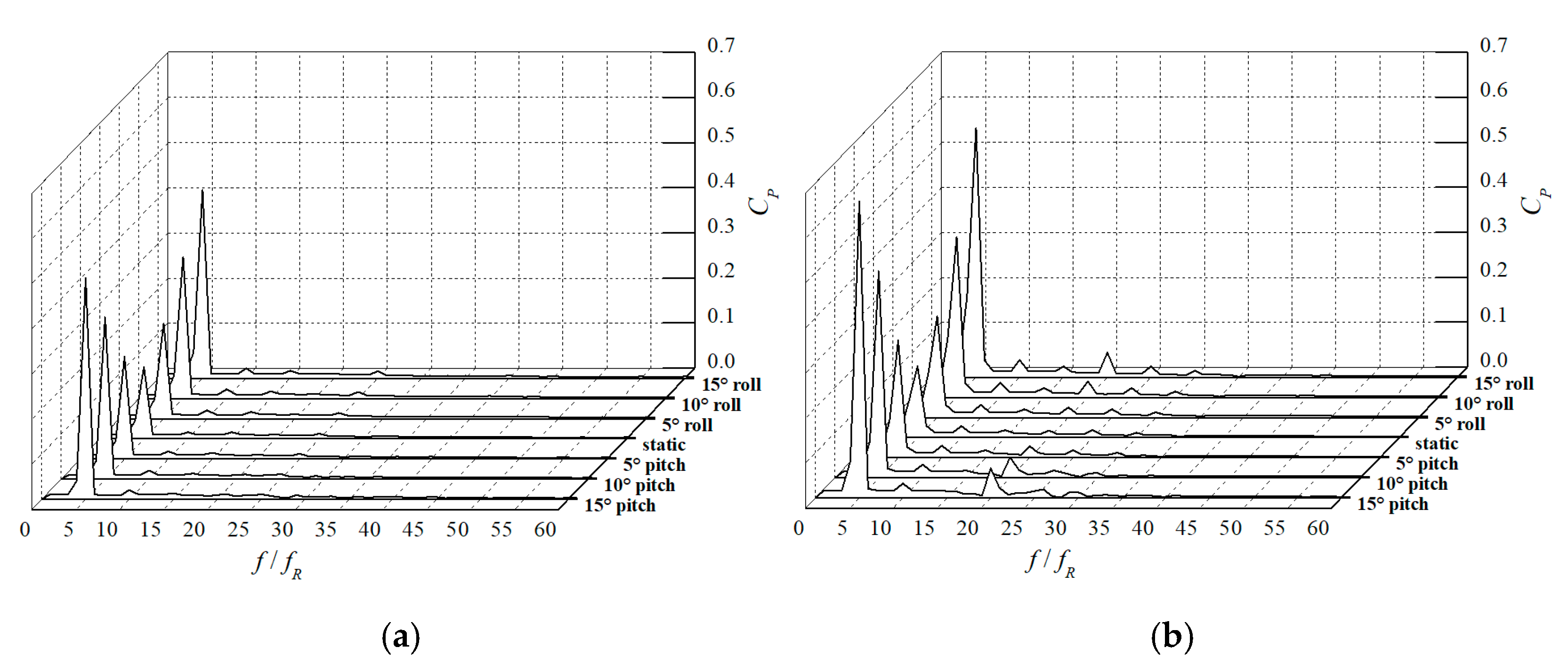
The frequency domain analyses for the pressure variations at the impeller inlet and outlet are listed in Figure 17. The monitoring point at the impeller inlet is set at the center of the circular section of the impeller inlet, while the monitoring point at the impeller outlet is arranged at the midpoint of the line connecting impeller outlet and volute tongue. Obvious pressure pulsation occurs at the frequencies less than 30 times the shaft frequency. As shown in Figure 17a, the maximum pressure pulsation amplitude appears at the low frequency. Compared to roll motion and pitch motion, the pressure amplitude is minimal when the pump is stationary. Especially, when the roll angle and pitch angle are the same, the amplitude of pressure pulsation under pitch motion is greater. This phenomenon indicates that the pitch motion induces the greater hydraulic excitation and fluid-induced vibration amplitude. Based on Figure 17b, in addition to the pressure pulsation at the low frequencies, the amplitude of pressure pulsation at 20 times the shaft frequency is evident at the impeller outlet. These additional pressure pulsations appear astatically, especially under the pitch motion.
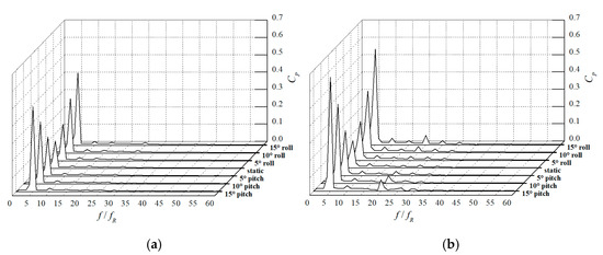
Figure 17.
Pressure variations in frequency domain: (a) impeller inlet, (b) impeller outlet.
3.3. Vortex Dynamic Characteristics under the Swing Motion
Under the swing motion, the flow in the marine pump undergoes unsteady variation. Due to the effects of swing inertia force, the flow velocity changes unconventionally. There are some changes that exist in the transport-velocity gradient and relative-velocity gradient that affect the vortex dynamic characteristics in the flow field of the pump. The vortex dynamic evolution is captured and analyzed based on the Q criterion identification method. The Q criterion is defined in the three-dimensional Cartesian coordinate system according to Equations (13)–(16).
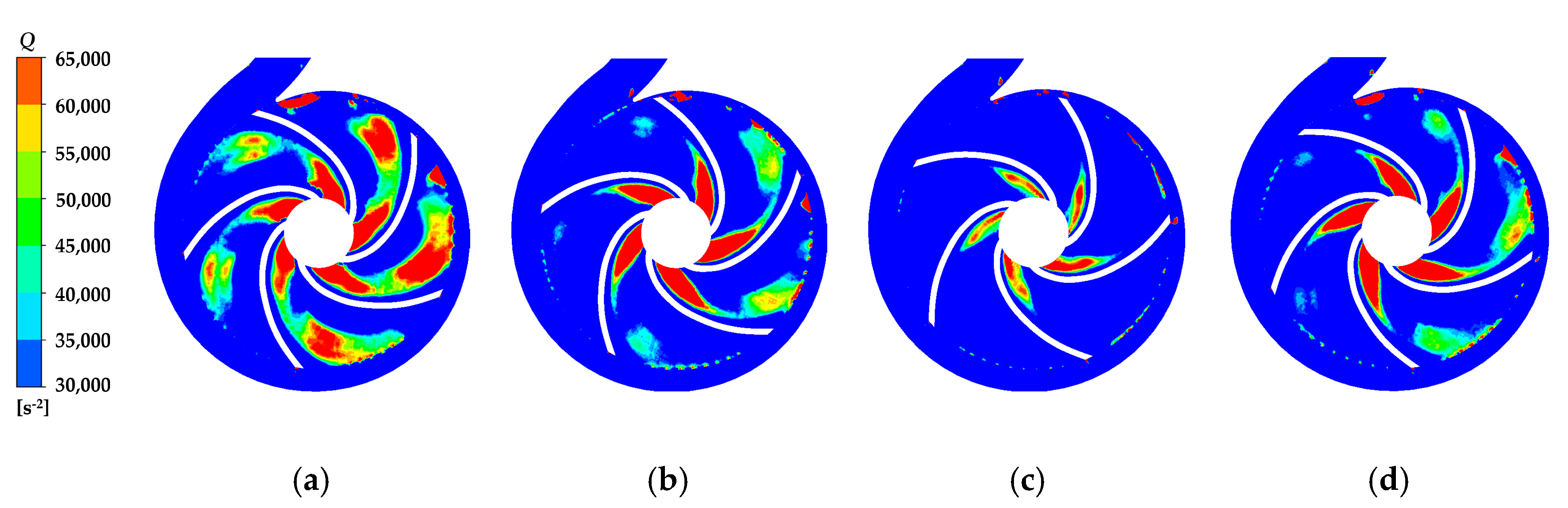
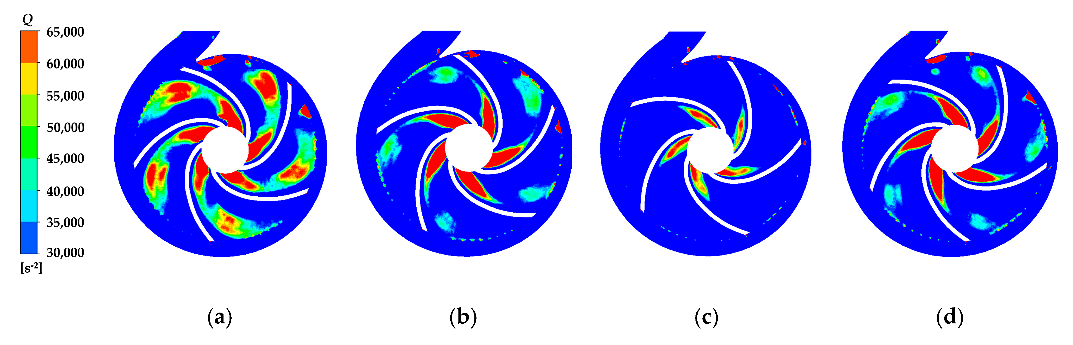
During one blade rotation period (Tb), the vortex intensity in the flow field of the pump under the static position is shown in Figure 18. The vortex cores mainly appear at the inlet and outlet of the impeller [38]. The vortex core always exists at the impeller inlet due to the change in the flow direction from axial to radial direction. Another vortex core at the impeller outlet is due to the stator-rotor interaction between the rotating blades and stationary volute [39,40]. Specifically, when the blade approaches the volute tongue, the vortex strength increases, as shown in Figure 18a,d. As the blade moves away from the tongue, the vortex intensity gradually weakens, and the significant vortex shedding is observed in Figure 18b. As the fluid flows, the vortex shedding continues to develop, and the energy carried by the shedding vortex gradually dissipates until completely dissipated, as seen in Figure 18c. When the pump is under the swing motion, the vortex intensity in one side of the impeller passage is strengthened, as shown in Figure 19 and Figure 20, similar to the flow characteristics described in Figure 15 and Figure 16. This phenomenon indicates that the evolution of vortex structures affects the flow dynamic behaviors in the pump.
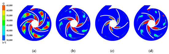
Figure 18.
Impeller vortex intensity within one blade rotation cycle under the static position: (a) Tb/4, (b) Tb/2, (c) 3Tb/4, (d) Tb.

Figure 19.
Impeller vortex intensity within one blade rotation cycle under the roll motion: (a) Tb/4, (b) Tb/2, (c) 3Tb/4, (d) Tb.

Figure 20.
Impeller vortex intensity within one blade rotation cycle under the pitch motion: (a) Tb/4, (b) Tb/2, (c) 3Tb/4, (d) Tb.
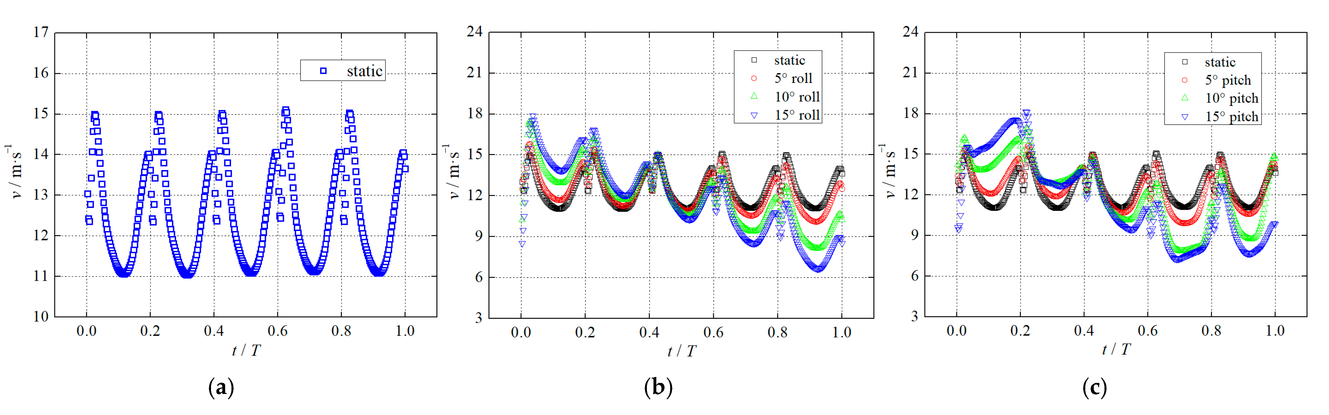
The vortex dynamic characteristics in the pump affect the flow, and the swing motion has a negative impact on the work done by the impeller, resulting in a decrease in pump head. Figure 21a provides the time-variant velocity variations at the impeller outlet near the volute tongue under the static position. Periodic velocity variations are observed, caused by the interaction between the blades and volute tongue. Obvious unsteady velocity changes occur at the impeller outlet under the roll motion and pitch motion, as shown in Figure 21b,c. As the swing angle increases, the amplitude of unsteady flow velocity also increases. Particularly, the flow-velocity amplitude varies in the flow chaos under the pitch motion, causing an uneven distribution of the impeller outlet velocity, which induces the unsteady pressure around the impeller outlet and hydraulic excitation on the impeller.
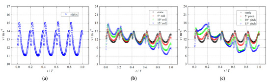
Figure 21.
Time-variant velocity variations at the impeller outlet near the volute tongue: (a) static position, (b) roll motion, (c) pitch motion.
4. Conclusions
This work investigates the effects of swing motion on the performance and inner flow characteristics of the marine centrifugal pump. A hydraulic test system with the six degree of freedom parallel motion platform is established to study the pump performance characteristics at the different heel angles of steady roll position and pitch position. Large eddy simulation with a shear-modified eddy viscosity model is employed to simulate unsteady flow behaviors and vortex dynamic characteristics in the model pump under the roll motion and pitch motion, based on the multiple reference coordinate system. The research results are as follows:
(1) The pump performance characteristics are tested under the different heel angles of steady roll position and pitch position. The pump head gradually decreases as the heel angle increases. The head at the roll position is lower than that at the pitch position under the rated flow condition at the same heel angle. Notably, the ψ has decreased by 7% to reach the minimum at the 15° heel angle of roll position, which indicates that the head of the marine pump needs to be increased by at least 7% during the pump selection process for the marine system.
(2) The fluid in the impeller passage is subjected to the additional inertial force of roll motion or pitch motion, when the pump is operating under an ocean environment. Obvious bias distribution in the high-speed fluid accumulation area and periodic flow-induced pulsation characteristics occur in the impeller passage. Under pitch motion, the pressure pulsation inside the pump is more pronounced, and the amplitude significantly increases at the other frequency, such as 20 times the shaft frequency.
(3) The vortex dynamic characteristics in the pump are captured and analyzed by the Q criterion identification method. Due to stator-rotor interaction, an obvious vortex core appears at the impeller outlet and is affected by the inertial force of swing motion. This vortex intensity is strengthened as the inertial force increases, which is one of the main reasons for inducing turbulent flow chaos.
Author Contributions
Data curation, Y.Y. and B.C.; Funding acquisition, Y.Y.; Investigation, Y.Y. and A.R.J.; Methodology, J.W.; Project administration, Y.Y.; Writing—original draft, Y.Y. and J.W. All authors have read and agreed to the published version of the manuscript.
Funding
This research was funded by the Natural Science Foundation of Jiangsu Province of China for Young Scholars (Grant No. BK20210883).
Data Availability Statement
The data presented in this study are available upon request from the corresponding author.
Conflicts of Interest
The authors declare no conflicts of interest.
Nomenclature
| ψ | head coefficient |
| η | hydraulic efficiency, % |
| CP | static pressure coefficient |
| QP | flow rate, m3/h |
| PT | total pressure, Pa |
| ρ | water density, kg/m3 |
| U2 | blade tip velocity, m/s |
| T | torque, N·m |
| Re | Reynolds number |
| V | flow velocity in the inlet pipe, m/s |
| D | inlet pipe diameter, m |
| υ | kinematic viscosity, m2/s |
| GCI | grid convergence index |
| Δx+ | Non-dimensional wall distances along the x axis |
| Δy+ | Non-dimensional wall distances along the y axis |
| Δz+ | Non-dimensional wall distances along the z axis |
| ui | flow velocity component at the i axis, m/s |
| μ | dynamic viscosity, Pa·s |
| μτ | eddy viscosity coefficient, Pa·s |
| u | flow velocity component at the x axis, m/s |
| v | flow velocity component at the y axis, m/s |
| w | flow velocity component at the z axis, m/s |
| θ | swing angle, degree |
| θmax | maximum swing angle, degree |
| Q | Q criterion number |
References
- Kim, M.H.; Cho, H.K.; Kim, B.J. Experimental and numerical investigation of flow dynamics in an upward bubbly flow in a tube undergoing oscillating rolling motion. Phys. Fluids 2024, 36, 013327. [Google Scholar] [CrossRef]
- Chang, S.; Kang, C.; Lee, C.; Yu, C. Effect of pitching and rolling motion on hydrothermal performance of rectangular channel flow enhanced by twisted-tape pin–fin array. Appl. Therm. Eng. 2021, 192, 116971. [Google Scholar] [CrossRef]
- Aziz, F.; Jo, D. Pressure fluctuations preceding critical heat flux during subcooled flow boiling in a one-side heated mini-channel under rolling motion. Ann. Nucl. Energy 2024, 198, 110306. [Google Scholar] [CrossRef]
- Yuan, H.; Tan, S.; Zhuang, N.; Lan, S. Flow and heat transfer in laminar–turbulent transitional flow regime under rolling motion. Ann. Nucl. Energy 2016, 87, 527–536. [Google Scholar] [CrossRef]
- Su, B.; Huang, K.; Lin, M.; Wang, Q. Experimental investigation on the flow patterns in a T-junction under steady and rolling motion conditions using PLIF. Chem. Eng. J. 2023, 465, 142772. [Google Scholar] [CrossRef]
- Basit, M.A.; Tian, W.; Chen, R.; Qiu, S.; Su, G. Numerical study of laminar flow and friction characteristics in narrow channels under rolling conditions using MPS method. Nucl. Eng. Technol. 2019, 51, 1886–1896. [Google Scholar] [CrossRef]
- Hwang, J.-S.; Lee, Y.-G.; Park, G.-C. Characteristics of critical heat flux under rolling condition for flow boiling in vertical tube. Nucl. Eng. Des. 2012, 252, 153–162. [Google Scholar] [CrossRef]
- Tan, S.; Wang, Z.; Wang, C.; Lan, S. Flow fluctuations and flow friction characteristics of vertical narrow rectangular channel under rolling motion conditions. Exp. Therm. Fluid Sci. 2013, 50, 69–78. [Google Scholar] [CrossRef]
- Kim, G.-W.; Yoo, J.-S.; Lee, C.W.; Hong, H.; Park, G.-C.; Cho, H.K. Critical heat flux correlations for tube and annulus geometries under inclination and rolling conditions. Appl. Therm. Eng. 2023, 225, 120131. [Google Scholar] [CrossRef]
- Li, Z.; Wang, M.; Fan, G.; Zeng, X.; Yan, Y.; Ma, F. Effects of rolling motion on flow and heat transfer characteristics in a tube bundle channel. Appl. Therm. Eng. 2023, 220, 119696. [Google Scholar] [CrossRef]
- Murtaza, H.; Basit, M.A.; Basit, R.; Tian, W. Numerical simulation of turbulent flow and friction characteristics through a loop of narrow Rrectangular channel under rolling motions. Nucl. Sci. Eng. 2023, 198, 1984–1997. [Google Scholar] [CrossRef]
- Chang, S.W.; Chen, Z.C. Hydrothermal performance of turbulent channel flow enhanced by spirally finned tube bundle in pitching and rolling motions. Therm. Sci. Eng. Prog. 2023, 37, 101567. [Google Scholar] [CrossRef]
- Chen, Y.; Ma, Y.; Liu, X.; He, D. Effect of rolling motion with large radius on flow and heat transfer characteristics of supercritical methane in a mini channel. Appl. Therm. Eng. 2021, 203, 117929. [Google Scholar] [CrossRef]
- Ghamkhar, K.; Ebrahimi, A.; Shariloo, K. Wavelet analysis of the flow field around an oscillating airfoil undergoing pure pitching motion at low Reynolds number. Phys. Fluids 2023, 35, 063607. [Google Scholar] [CrossRef]
- Xu, B.; Kang, H.; Shen, X.; Li, Z.; Cai, X.; Hu, Z. Aerodynamic analysis of a downwind offshore floating wind turbine with rotor uptilt angles in platform pitching motion. Ocean Eng. 2023, 281, 114951. [Google Scholar] [CrossRef]
- Guo, Y.; Wang, X.; Mei, Y.; Ye, Z.; Guo, X. Effect of coupled platform pitch-surge motions on the aerodynamic characters of a horizontal floating offshore wind turbine. Renew. Energy 2022, 196, 278–297. [Google Scholar] [CrossRef]
- Yuan, Y.; Gong, W.; Wang, G.; Wang, J. Research on the performance characteristics and unsteady flow mechanism of a cen-trifugal pump under pitch motion. Water 2023, 15, 3706. [Google Scholar] [CrossRef]
- Yuan, Y.; Fang, Y.; Tang, L. Effects of non-uniform elbow inflow on the unsteady flow and energy development characteristics of a centrifugal pump. Phys. Fluids 2023, 35, 015152. [Google Scholar] [CrossRef]
- Parfenyev, V. Statistical analysis of vortex condensate motion in two-dimensional turbulence. Phys. Fluids 2024, 36, 015148. [Google Scholar] [CrossRef]
- Kolokolov, I.V.; Ogorodnikov, L.L.; Vergeles, S.S. Structure of coherent columnar vortices in three-dimensional rotating turbulent flow. Phys. Rev. Fluids 2020, 5, 034604. [Google Scholar] [CrossRef]
- Frishman, A. The culmination of an inverse cascade: Mean flow and fluctuations. Phys. Fluids 2017, 29, 125102. [Google Scholar] [CrossRef]
- An, Y.-J.; Shin, B.R. Numerical investigation of suction vortices behavior in centrifugal pump. J. Mech. Sci. Technol. 2011, 25, 767–772. [Google Scholar] [CrossRef]
- Al-Obaidi, A.R.; Alhamid, J. Investigation of the main flow characteristics mechanism and flow dynamics within an axial flow pump based on different transient load conditions. Iran. J. Sci. Technol. Trans. Mech. Eng. 2023, 47, 1397–1415. [Google Scholar] [CrossRef]
- Kim, S.J.; Yang, H.M.; Park, J.; Kim, J.H. Investigation of internal flow characteristics by a Thoma number in theturbine mode of a Pump–Turbine model under high flow rate. Renew. Energy 2022, 199, 445–461. [Google Scholar] [CrossRef]
- Ye, W.; Ikuta, A.; Chen, Y.; Miyagawa, K.; Luo, X. Investigation on the effect of forward skew angle blade on the hump charac-teristic in a mixed flow pump using modified partially averaged Navier-Stokes model. Renew. Energy 2021, 170, 118–132. [Google Scholar] [CrossRef]
- El-Emam, M.A.; Zhou, L.; Omara, A.I. Predicting the performance of aero-type cyclone separators with different spiral inlets under macroscopic bio-granular flow using CFD–DEM modelling. Biosyst. Eng. 2023, 233, 125–150. [Google Scholar] [CrossRef]
- Kolokolov, I.V.; Lebedev, V.V.; Tumakova, M.M. Correlations of vorticity inside a coherent vortex. J. Exp. Theor. Phys. 2023, 136, 785–794. [Google Scholar] [CrossRef]
- Tong, Z.; Shang, B. Investigating three-dimensional vortex evolution in centrifugal pump under rotating stall conditions using tomographic particle image velocimetry. Phys. Fluids 2024, 36, 067101. [Google Scholar] [CrossRef]
- Tang, L.; Wang, W.; Zhang, C.; Wang, Z.; Yuan, S. Influence of Runner Downstream Structure on the Flow Field in the Runner of Small-Sized Water Turbine. Machines 2024, 12, 392. [Google Scholar] [CrossRef]
- Song, X.; Jin, Y.; Wang, Z.; Presas, A.; Tang, F.; Liu, C. Energy dissipation and time–frequency analysis of characteristics induced by vortex breakdown in an axial flow pump. Phys. Fluids 2024, 36, 065102. [Google Scholar] [CrossRef]
- Zhou, L.; Hang, J.; Bai, L.; Krzemianowski, Z.; El-Emam, M.A.; Yasser, E.; Agarwal, R. Application of entropy production theory for energy losses and other investigation in pumps and turbines: A review. Appl. Energy 2022, 318, 119211. [Google Scholar] [CrossRef]
- Stremler, M.A. On relative equilibria and integrable dynamics of point vortices in periodic domains. Theor. Compu-Tational Fluid Dyn. 2010, 24, 25–37. [Google Scholar] [CrossRef]
- Alawadhi, K.; Alzuwayer, B.; Alrahmani, M.; Murad, A. Evaluation of the Erosion Characteristics for a Marine Pump Using 3D RANS Simulations. Appl. Sci. 2021, 11, 7364. [Google Scholar] [CrossRef]
- Abdelsalam, S.I.; Magesh, A.; Tamizharasi, P.; Zaher, A.Z. Versatile response of a Sutterbynanofluid under activationenergy: Hyperthermia therapy. Int. J. Numer. Heat Fluid Flow 2023, 7, 408–428. [Google Scholar]
- Yan, B. Review of the nuclear reactor thermal hydraulic research in ocean motions. Nucl. Eng. Des. 2017, 313, 370–385. [Google Scholar] [CrossRef]
- Jin, G.; Yan, C.; Sun, L.; Xing, D. Effect of rolling motion on transient flow resistance of two-phase flow in a narrow rectangular duct. Ann. Nucl. Energy 2014, 64, 135–143. [Google Scholar] [CrossRef]
- Wang, Z.; He, Y.; Duan, Z.; Huang, C.; Yuan, Y.; Li, M.; Liu, S. Effects of rolling motion on transient flow behaviors of gas-liquid two-phase flow in horizontal pipes. Ocean Eng. 2022, 255, 111482. [Google Scholar] [CrossRef]
- Capurso, T.; Bergamini, L.; Torresi, M. Performance analysis of double suction centrifugal pumps with a novel impeller con-figuration. Energy Convers. Manag. X 2022, 14, 100227. [Google Scholar]
- Silveira, N.; Meghoe, A.; Tinga, T. Integration of multiple failure mechanisms in a life assessment method for centrifugal pump impellers. Adv. Mech. Eng. 2023, 15, 16878132231175755. [Google Scholar] [CrossRef]
- Oro, J.F.; Perotti, R.B.; Vega, M.G.; González, J. Effect of the radial gap size on the deterministic flow in a centrifugal pump due to impeller-tongue interactions. Energy 2023, 278, 127820. [Google Scholar] [CrossRef]


Disclaimer/Publisher’s Note: The statements, opinions and data contained in all publications are solely those of the individual author(s) and contributor(s) and not of MDPI and/or the editor(s). MDPI and/or the editor(s) disclaim responsibility for any injury to people or property resulting from any ideas, methods, instructions or products referred to in the content. |
© 2024 by the authors. Licensee MDPI, Basel, Switzerland. This article is an open access article distributed under the terms and conditions of the Creative Commons Attribution (CC BY) license (https://creativecommons.org/licenses/by/4.0/).