Article

A Reconfigurable Architecture for Industrial Control Systems: Overview and Challenges

1
College of Mechatronics and Control Engineering, Shenzhen University, Shenzhen 518060, China
2
China Nuclear Power Technology Research Institute Co., Ltd., Shenzhen 518026, China
*
Author to whom correspondence should be addressed.
Machines 2024, 12(11), 793; https://doi.org/10.3390/machines12110793
Submission received: 15 October 2024 / Revised: 4 November 2024 / Accepted: 8 November 2024 / Published: 9 November 2024
(This article belongs to the Section Automation and Control Systems)

Abstract

:
The closed architecture and stand-alone operation model of traditional industrial control systems limit their ability to leverage ubiquitous infrastructure resources for more flexible and intelligent development. This restriction hinders their ability to rapidly, economically, and sustainably respond to mass customization demands. Existing proposals for open and networked architectures have failed to break the vicious cycle of closed architectures and stand-alone operation models because they do not address the core issue: the tight coupling among the control, infrastructure, and actuator domains. This paper proposes a reconfigurable architecture that decouples these domains, structuring the control system across three planes: control, infrastructure, and actuator. The computer numerical control (CNC) system serves as a primary example to illustrate this reconfigurable architecture. After reviewing open and networked architectures and discussing the characteristics of this reconfigurable architecture, this paper identifies three key challenges: deterministic control functionality, the decoupling of control modules from infrastructures, and the management of control modules, infrastructures, and actuators. Each challenge is examined in detail, and potential solutions are proposed based on emerging technologies.

1. Introduction

The convergence of Information Technology (IT) and Communication Technology (CT) has led to the creation of ubiquitous infrastructure resources, such as computing, networking, storage, and operating systems. These resources drive the digitalization and dynamic connectivity of various manufacturing assets, forming the foundation of industrial IoT, a key technology in Industry 4.0.
Figure 1 illustrates the current state of the industrial IoT by mapping it to the ISA-95 automation pyramid model. On the one hand, thanks to Infrastructure-as-a-Service (IaaS) and Platform-as-a-Service (PaaS), control and monitoring applications in the upper three levels have increasingly adopted standardized and modular development patterns and are offered in a Software-as-a-Service (SaaS) model [1,2,3,4,5].
On the other hand, the lower two layers have not fully utilized the ubiquitous infrastructure resources due to the closed architecture and stand-alone operation model of traditional control systems, which primarily include programmable logic controllers (PLCs) and computer numerical control (CNC) systems. Given that CNC encompasses complex and hybrid domain knowledge, with PLCs serving as a sub-domain, this paper focuses on CNC as a primary example for discussion. As shown in Figure 1, CNC software is infrastructure-dependent, proprietary, and monolithic. It operates in a stand-alone manner—one CNC system typically controls one machine tool, forming a CNC machine tool (CNCMT) unit. This setup prevents users from seamlessly modifying, distributing, or migrating CNC software to other infrastructures or dynamically integrating machine tools. Instead, users must repeatedly purchase, install, commission, and maintain multiple CNC systems with similar functionality to support different machine tools.
In the current industrial IoT landscape, as a result, the CNC system is often modeled as a read-only attribute of the machine tool’s digital twin, merely reflecting its manufacturing capabilities [6]. As the scale and complexity of CNC systems grow, they become increasingly closed, hindering the advancement of CNC systems toward greater intelligence. From an infrastructure perspective, the inability to scale these resources results in inefficiency, with resources either underutilized or wasted [7]. Moreover, from the perspective of the industrial IoT, the widening gap between IT/CT and Operational Technology (OT) creates obstacles to the transformation of the automation pyramid from a static framework to a dynamic, adaptive system.
In light of the shift towards new IT/CT infrastructure paradigms, there is a compelling need to design a new architecture and operational model for industrial automation systems. This paper proposes a reconfigurable architecture, using CNC systems as a primary example. By abstracting CNC functions, infrastructure resources, and machine tools into three distinct and independent resources, this architecture allows CNC systems to be constructed based on three planes:
  • Control domain plane: CNC functionality is reconfigured based on specific machining requirements, enabling flexible adaptation to various tasks.
  • Infrastructure domain plane: CNC modules implementing various CNC functions are distributed across heterogeneous infrastructure resources, ensuring high portability and resource efficiency.
  • Actuator domain plane: CNC systems are dynamically equipped to machine tools on demand by connecting infrastructure resources and machine tools.
To summarize the challenges associated with this proposed reconfigurable architecture, current research on industrial automation architectures is reviewed. Based on this analysis, advanced technologies are explored, and their potential to enhance the reconfigurable architecture is assessed. The remainder of this paper is organized as follows: Section 2 provides a brief introduction to CNC systems, setting the stage for the subsequent sections, and reviews the architectures of industrial control systems. Section 3 presents an overview of the proposed reconfigurable architecture, illustrated through a case study. Section 4 outlines three key challenges of the reconfigurable architecture based on the review of architectures and discusses potential solutions. Finally, Section 5 concludes the paper and outlines directions for future work.

2. Brief Review of Industrial Control System Architectures

2.1. A Brief Introduction to CNC Systems

As the “brain” of machine tools, the CNC system is a complex industrial control system characterized by behaviors that encompass both discrete actions—such as on/off switching and logical operations—and continuous actions, such as the movement of feed axes. These behaviors are typically defined in a part program, which is often written by using G/M codes. CNC functionality is generally divided into three main functions: the human–machine interface (HMI), the numerical control kernel (NCK), and the PLC [8]. The HMI facilitates user interaction, the NCK manages continuous behaviors, and the PLC handles discrete operations.
In addition to these core functions, modern CNC systems often integrate auxiliary functions, such as communication and tool management, and follow an intelligent development trend. Since the CNC system must react to both operator inputs and environmental stimuli in real time, it typically relies on a real-time operating system (RTOS) to ensure the deterministic execution of CNC software.

2.2. Open Architecture

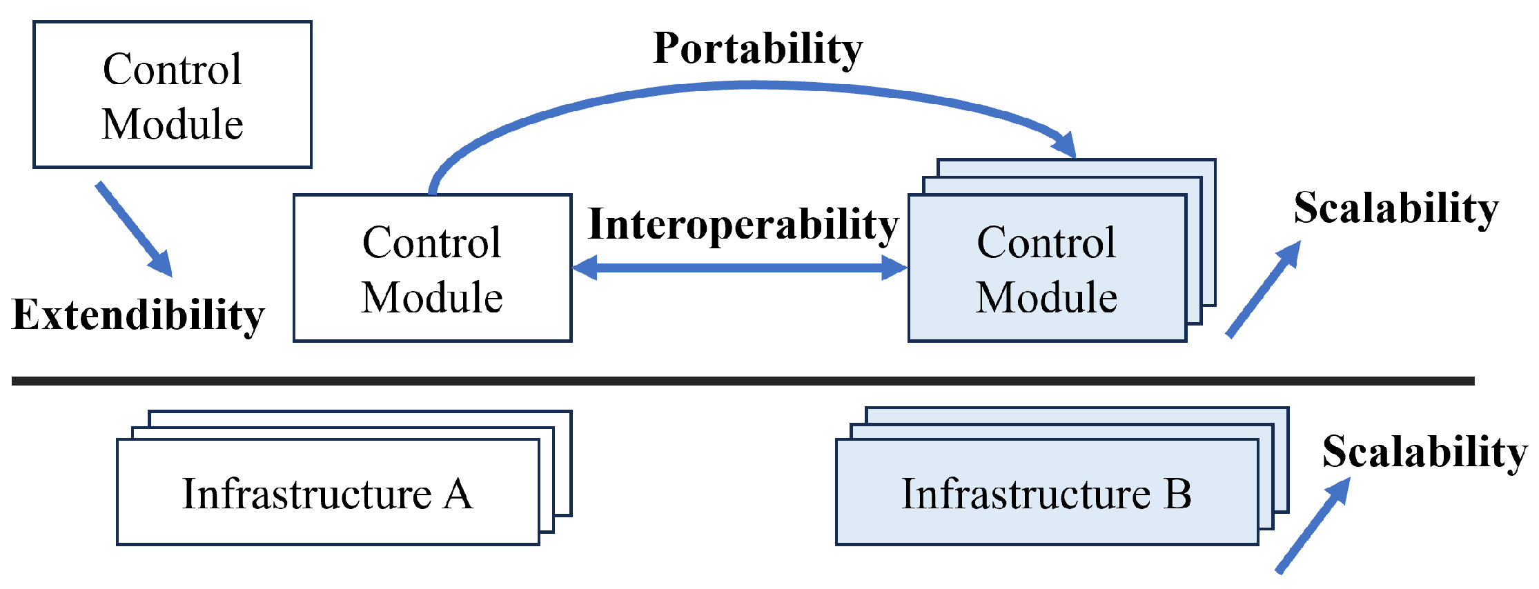
Driven by the evolution of computer architecture and the object-oriented paradigm, open architecture is proposed to deal with the infrastructure-oriented and software-monolithic issues of traditional control systems. As Figure 2 illustrates, the degree of openness is often estimated by the following criteria [9]:
  • Extendibility and interoperability: Carious control modules running on diverse infrastructures can interact in a standard way to compose control software.
  • Portability: Control modules can run on different infrastructures.
  • Scalability: Control modules and infrastructures can scale on demand.
Over the past three decades, numerous open CNC prototypes have been developed, with most following the component-based software engineering (CBSE) approach. This approach involves developing CNC modules as individual components, with each module responsible for implementing a specific CNC function. The behavior of CNC modules is typically modeled by using a finite state machine (FSM), where each module operates in multiple states and transitions between these states are triggered by events [10,11]. The following paragraphs provide a brief review of CBSE-based open CNC prototypes, focusing on two key aspects: CNC component granularity and CNC component models.
Regarding CNC component granularity, it is typically determined by a top-down decomposition of control functionality. As mentioned in the above section, CNC functionality is overall divided into HMI, NCK, and PLC. However, the further decomposition of these three functions varies among prototypes, resulting in non-uniform CNC component granularity. This lack of standardization in component granularity hinders the interoperability of CNC components across different systems.
Concerning CNC component models, general-purpose component models such as the CORBA Component Model (CCM) [12], the Microsoft Component Model (COM) [13], and IEC 61499 [14,15] are commonly employed. However, these models tend to be language- or platform (runtime)-dependent, reducing the portability and interoperability of CNC components.
In summary, current open CNC prototypes have yet to achieve a high level of openness, particularly in terms of interoperability and portability. From an infrastructure perspective, moreover, these prototypes often target static, homogeneous infrastructures—such as PCs or PCs with add-on boards—which resemble traditional CNC systems [16,17]. A more detailed review of CBSE-based open CNC prototypes is available in the authors’ previous work [18].

2.3. Networked Architecture

The rapid development of cloud computing and Communication Technology has led to the emergence of networked architectures, often referred to as cloud-based control systems or networked control systems (NCSs), where control software migrates from on-site infrastructures to the cloud or other remote infrastructures and connect sensors and actuators via a shared band-limited digital communication network. In this case, CNC functionality is often exposed as services, commonly known as Control (CNC)-as-a-Service (CaaS) [19,20,21]. This architecture not only leverages scalable infrastructure resources but also decouples the traditional fixed connections among control systems, sensors, and actuators, enabling a plug-and-play operational model. For instance, T. Cruz et al. introduced the concept of a virtualized PLC using a software-defined network (SDN) infrastructure to enable the flexible reconfiguration of virtual channels on the I/O fabric, replacing the dedicated PLC I/O bus [22].
However, the networked architecture faces a significant challenge: ensuring the ability to respond to stimuli in real time, given the undetermined nature of the network (including issues like network-induced delays and packet loss). This challenge has drawn considerable attention in the field of NCSs, which can be categorized into two main areas: “control of networks” and “control over networks”. The former focuses on improving the quality of service (QoS) of networks, while the latter aims to enhance control robustness against network disadvantages [23,24]. Within control systems, the latter has been extensively discussed. However, current discussions largely remain at a theoretical level. A practical solution involves distributing control functions across cloud–edge environments based on time sensitivity and leveraging heterogeneous communication technologies. This paper mainly focuses on the practical solutions. Based on their deployment patterns, current networked CNC prototypes can be categorized into three types:
  • Extra-low-time-sensitivity CNC modules (e.g., management and maintenance functions) are deployed on the cloud (or other remote infrastructures) and interact with traditional CNC systems via general networks, while traditional CNC systems connect actuators (i.e., machine tools) via conventional real-time communication technologies (e.g., field bus and real-time Ethernet). This approach extends traditional CNC systems by adding intelligence and remote operation capabilities [6].
  • CNC software is deployed on edge infrastructures near the machine tools, connecting multiple machine tools simultaneously through scaling. However, this configuration compromises real-time performance, as multiple processes must share the constrained and static resources of the edge infrastructure.
  • High-time-sensitivity CNC modules remain at edge-level infrastructures that connect machine tools via conventional real-time communication technologies, while other CNC modules are all migrated to remote infrastructures. To mitigate potential latency issues, an additional cache is often deployed at the edge to buffer data [20].
Overall, the networked architecture primarily addresses infrastructure-oriented challenges. Unlike open CNC prototypes, CNC modules in networked architectures are distributed across hybrid infrastructures based on their time sensitivity. However, in current prototypes, the time sensitivity of CNC modules is fixed, resulting in relatively static distributed deployment. In other words, CNC software remains coupled with the underlying infrastructure. Moreover, while the networked architecture enables dynamic connections between CNC systems and machine tools, the stand-alone operation model issue has not been thoroughly explored or addressed independently in current prototypes.

3. Overview of Reconfigurable Architecture

The closed architecture of traditional industrial control systems enforces a stand-alone operation model, which, in turn, reinforces the closed architecture, creating a vicious cycle that obstructs the convergence of OT with IT/CT. Neither open architectures nor networked architectures have effectively broken this cycle. At its core, this cycle stems from the tight coupling among the control domain, infrastructure domain, and actuator domain. To address this, a reconfigurable architecture is proposed, built on the decoupling of these three domains and the reconstructing of control systems based on the control domain plane, infrastructure domain plane, and actuator domain plane.

3.1. Functional Framework of Reconfigurable Architecture

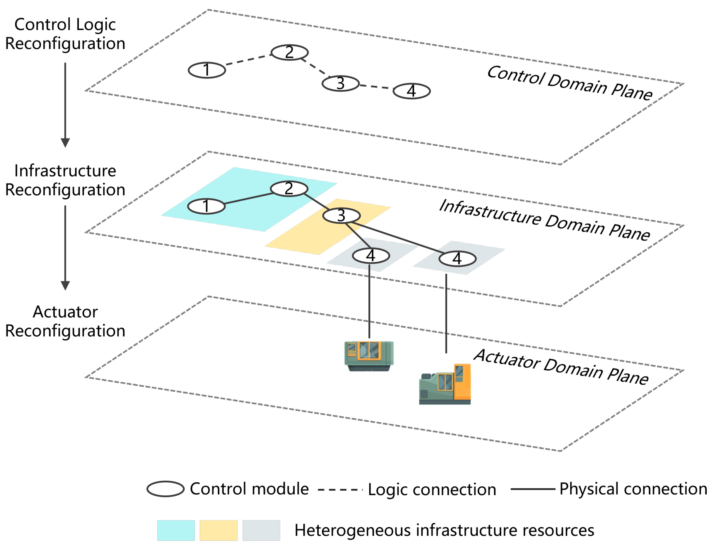
As illustrated in Figure 3, control modules, infrastructure resources, and actuators are structured as three distinct and independent resource objects, distributed across the control domain plane, infrastructure domain plane, and actuator domain plane, respectively. On the control domain plane, control modules are logically interconnected to achieve specific control functionalities (i.e., control logic reconfiguration or control functionality reconfiguration). On the infrastructure domain plane, these control modules are deployed across heterogeneous infrastructure resources within cloud–edge environments, where the logical connections are realized through physical links between infrastructure resources (e.g., shared memory, shared files, and 5G). Thus, from a control system perspective, infrastructures are reconfigured on demand on this plane. Moreover, on the actuator domain plane, actuators are endowed with control functionalities by being physically connected to infrastructure resources (e.g., Fieldbus and EtherCAT), that is, actuator reconfiguration.
Particularly, in Figure 3, control module (4) is duplicated and distributed across multiple infrastructures, each connected to a different actuator. This demonstrates that the functionality defined within the control domain plane can equip multiple actuators simultaneously. In other words, control modules (1, 2, 3) are shared across these actuators, as opposed to the traditional control system model, where each module serves a single actuator.

3.2. Case Study

This section further illustrates the reconfigurable architecture through a case study, demonstrating the reconfiguration of a CNC system in response to the addition of a tool library to a machine tool, thereby extending its machining range.
As mentioned in Section 2.1, the NCK is primarily responsible for controlling the movements of the feed axes. Generally, the NCK processes G/M codes to generate the corresponding target positions for the feed axes and operation commands (e.g., spindle on/off) and then sends these target positions to the servo drivers. As illustrated in Figure 4, this continuous process is typically carried out by three CNC modules:
  • Interpretation: This module translates G/M codes into internal commands, ensuring that the high-level instructions from the part program are converted into NCK-readable formats.
  • Look-ahead velocity plan: This module plans the speed of the feed axes in advance. By considering the kinematic constraints of the machine tool (e.g., acceleration and jerk limits) and the sharp corners in the tool trajectory, this module ensures smooth and efficient transitions between different movements, preventing sudden changes in speed that could lead to mechanical stress or suboptimal machining quality.
  • Interpolation: This module discretizes the planned tool trajectory into a series of small, precise target positions. These positions are sent to the servo drivers at regular intervals. This module ensures that the tool follows the programmed trajectory accurately by calculating the exact position of each axis at every time step.
In traditional CNC systems, these three modules are typically compiled and deployed together on an RTOS to ensure deterministic execution. Users must write G/M codes in compliance with the specific CNC vendor’s specifications; otherwise, the integrated interpretation module cannot process the program. For instance, part programs written for LinuxCNC mostly cannot be processed by Siemens Sinumerik systems directly. Furthermore, when facing the reconfiguration of machine tools, such as adding new modules, like a tool library, users face significant challenges in updating the interpretation module to accommodate additional functionality, such as tool management or handling tool change commands (e.g., M6).
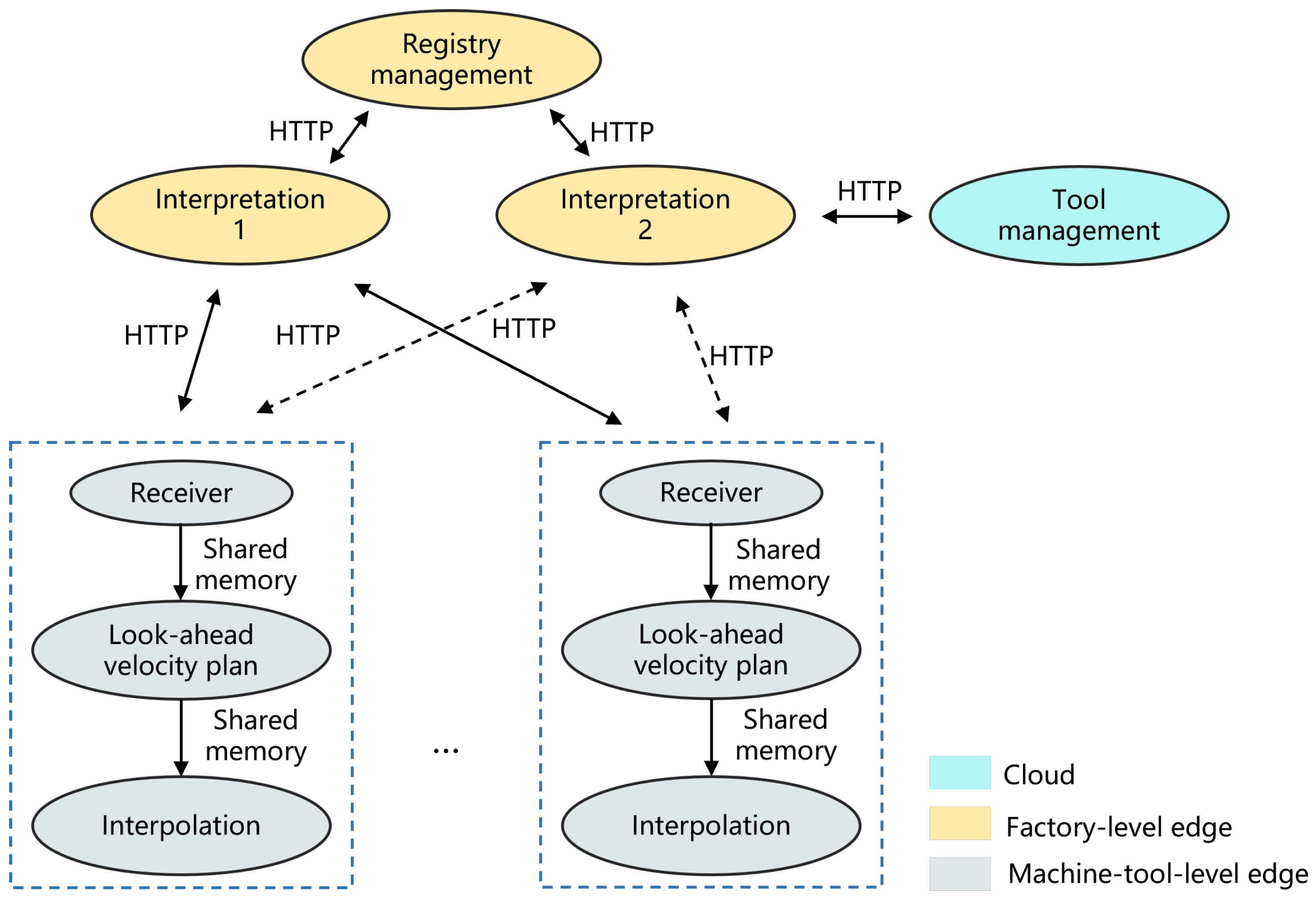
The reconfigurable architecture can address this issue, as Figure 5 illustrates. On the control domain plane, three additional CNC modules are added:
  • Tool management: This module oversees the lifecycle of all tools within the factory. The interpretation module (2) establishes a logical connection with this module to retrieve necessary tool information.
  • Registry management: This module manages the registration of machine tools and their associated edge devices (e.g., network addresses of machine-tool-level edges). Every machine tool and its associated edge must be registered within this module. It connects to the interpretation modules to configure network addresses.
  • Receiver: This module receives the internal commands generated by the interpretation module and stores them at the edge. Subsequently, it invokes the look-ahead velocity planning and interpolation modules. As such, it also connects to the interpretation modules.
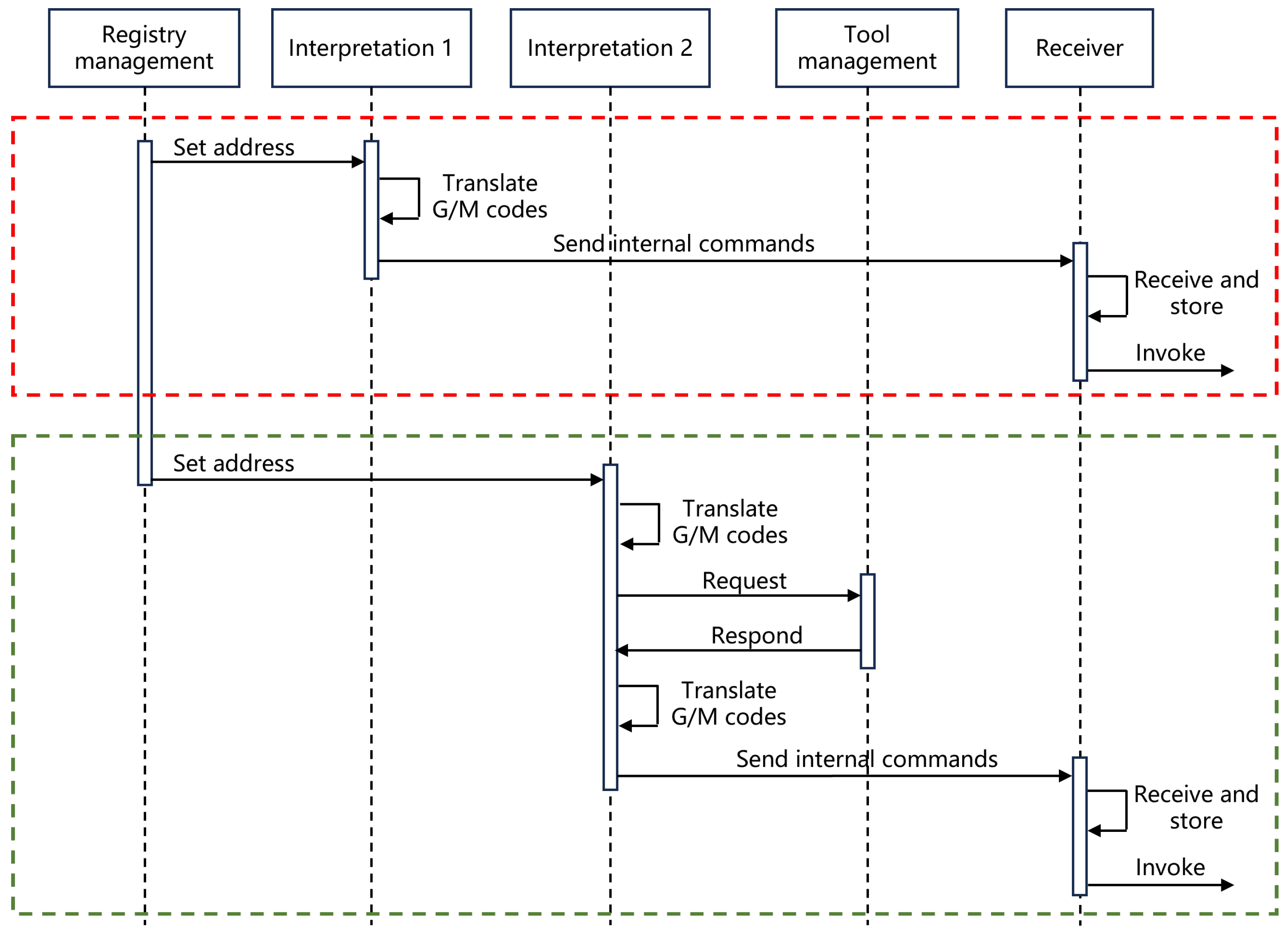
The execution sequence of this reconfigured NCK is illustrated in Figure 6. Initially, the registry management module communicates with the interpretation module (1) to configure the address of the machine-tool-level edge, as shown in the red rectangle of Figure 6. Once the address is set, the interpretation module (1) translates the G/M codes into internal commands and sends them to the receiver module based on the configured address. The receiver module then receives and stores these commands. Once this process is complete, the receiver module invokes the look-ahead velocity planning and interpolation modules.
In response to the addition of a tool library, the registry management module varies to communicate with the interpretation module (2) to configure the appropriate address, as indicated in the green rectangle of Figure 6. During the translation process, the interpretation module (2) sends requests to the tool management module to retrieve the necessary tool information. Following this, it sends the internal commands to the receiver module, similar to the previous process.
In summary, from the machine tool’s perspective, it dynamically receives internal commands from different interpretation modules, allowing it to adapt to mechanical extensions, such as the integration of a tool library.
On the infrastructure domain plane, the tool management module is deployed on the cloud, while the registry management and interpretation modules are deployed on a factory-level edge. As illustrated in Figure 5, communication between these modules is facilitated through message exchanges over HTTP. On the machine-tool-level edge, which is equipped with an RTOS, the receiver, look-ahead velocity planning, and interpolation modules are deployed. Communication among these modules is implemented through shared memory.
On the actuator domain plane, as illustrated in Figure 5, the interpretation modules are shared across all machine tools within the factory, meaning they can generate internal commands for any machine tool in the facility. Additionally, although the modules deployed on the machine-tool-level edge are dedicated to the specific machine tool they are connected to, they can also serve multiple machines through duplication and dynamic deployment.

3.3. Characteristics of Reconfigurable Architecture

Compared with open and networked architectures, the reconfigurable architecture presents two distinctive characteristics:
  • First, it enables a dynamic, many-to-many interaction among CNC modules, infrastructure resources, and machine tools, optimizing their utilization and allowing for adaptation to diverse production tasks in the mass customization market.
  • Second, it establishes a dynamic, many-to-many relationship between users and vendors. In this context, users, who can be either end-users of machine tools or machine tool vendors, consume CNC modules. Vendors, on the other hand, supply these CNC modules. This flexible arrangement allows users to assemble CNC systems by integrating modules from multiple vendors, while a single vendor’s CNC modules can serve multiple users.

4. Challenges and Methods of the Reconfigurable Architecture

According to the review of open architectures and networked architectures, as well as the characteristics of reconfigurable architectures, the following crucial challenges of reconfigurable architectures are summarized and discussed.

4.1. Deterministic Description of CNC Functionality

In current open CNC prototypes, as discussed in Section 2.2, maintaining a uniform granularity for CNC modules is essential to enhancing the system’s openness. However, defining a standard granularity is hard, if not impossible, particularly as CNC functionality becomes increasingly complex and large-scale. Moreover, as the number of CNC modules grows and/or the modules become more refined, the number of states in the CNC system expands significantly within the FSM-based behavior model. This makes it progressively more difficult to describe the functionality of a CNC system in a deterministic manner.
Essentially, the FSM-based behavior model describes CNC functionality from a software application perspective rather than from a CNC domain perspective, as the FSM serves as a micromodel for software applications. However, as discussed in Section 2.1, the CNC domain is a hybrid system composed of both discrete and continuous behavior sub-domains.
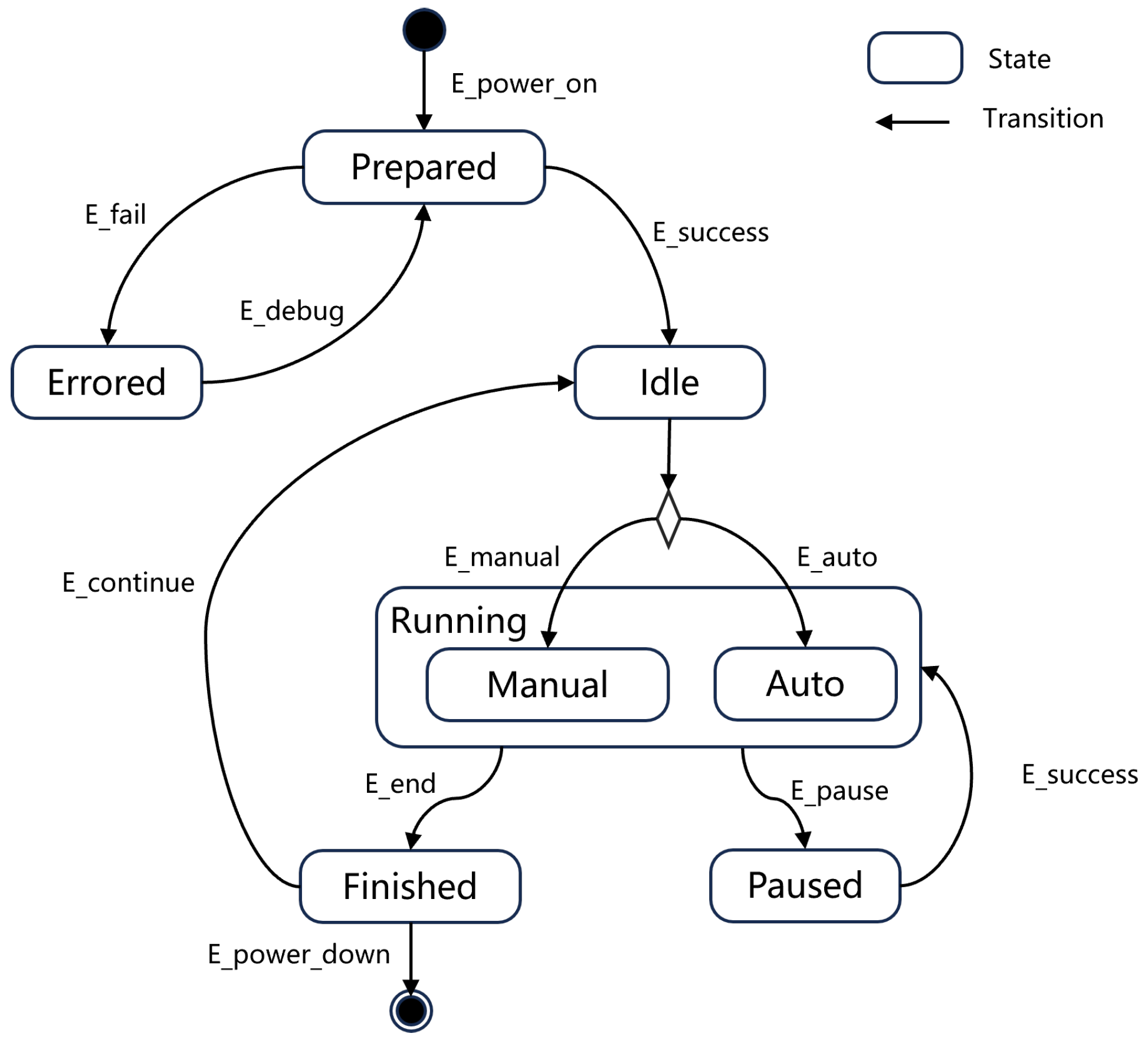
For the discrete behavior sub-domain, which aligns with a discrete event system, the FSM is an appropriate model for its representation. For example, Figure 7 illustrates the overall functionality of a CNC system using an FSM. When the power-on event (E_power_on) occurs, the CNC machine tool transitions from the Initial state to the Prepared state. If a failure event (E_fail) is triggered during the preparation process, the system moves to the Errored state and returns to Prepared upon receiving a debug event (E_debug). Otherwise, if a success event (E_success) is generated, the system transitions to the Idle state. From the Idle state, the system can enter a specific Running state (either Manual or Auto) depending on the event—either E_manual or E_auto. If a pause event (E_pause) is triggered by the operator or due to an error, the system transitions from Running to the Paused state. Alternatively, if the machining process finishes and an end event is triggered, the system moves to the Finished state. The system can return to the Running state from Paused when a success event occurs, indicating the process can resume. Additionally, the system transitions from Finished to Idle when a continue event is triggered, such as when the finished workpiece is offloaded, and a new one is loaded.
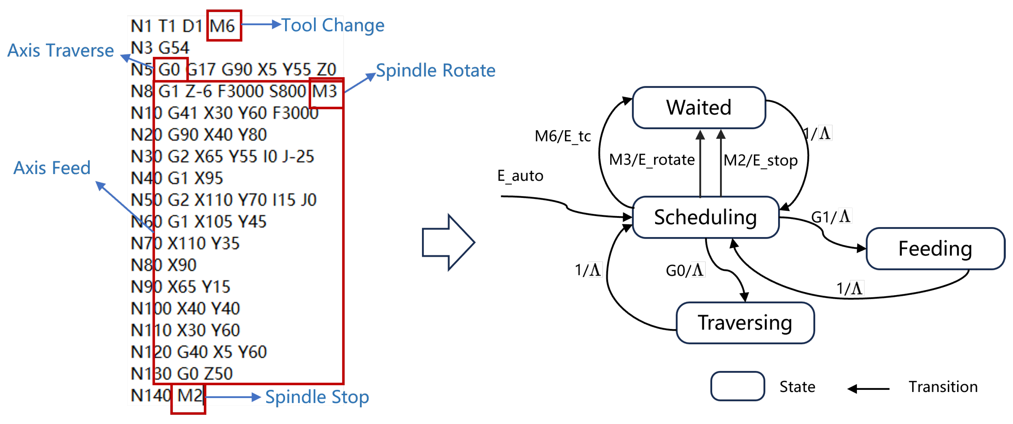
In particular, the Auto state is a composite state, and its internal state transition graph can be derived from G/M codes. As shown in Figure 8, the initial state of the Auto state is Scheduling. If the G/M code “M6” is read, a tool change event (E_tc) is generated, and the state transitions to Waited. Once the tool change is completed and a confirmation event (1) is received, the state returns to Scheduling without generating any further events (denoted by A, meaning no event is output). Similarly, if “M3” is read, a spindle rotate event (E_rotate) is triggered, and the state moves to Waited. Once the spindle rotation completes, the state returns to Scheduling. The same process applies to “M2” (program end command). Moreover, when “G0” is read, the state transitions to Traversing, and no event is output. After the CNC machine tool finishes traversing, the state reverts to Scheduling. When “G1” is read, the state transitions to Feeding. Once feeding is completed, the state returns to Scheduling. If there are no more commands, the Auto state transitions to the Finished state, as described in Figure 7.
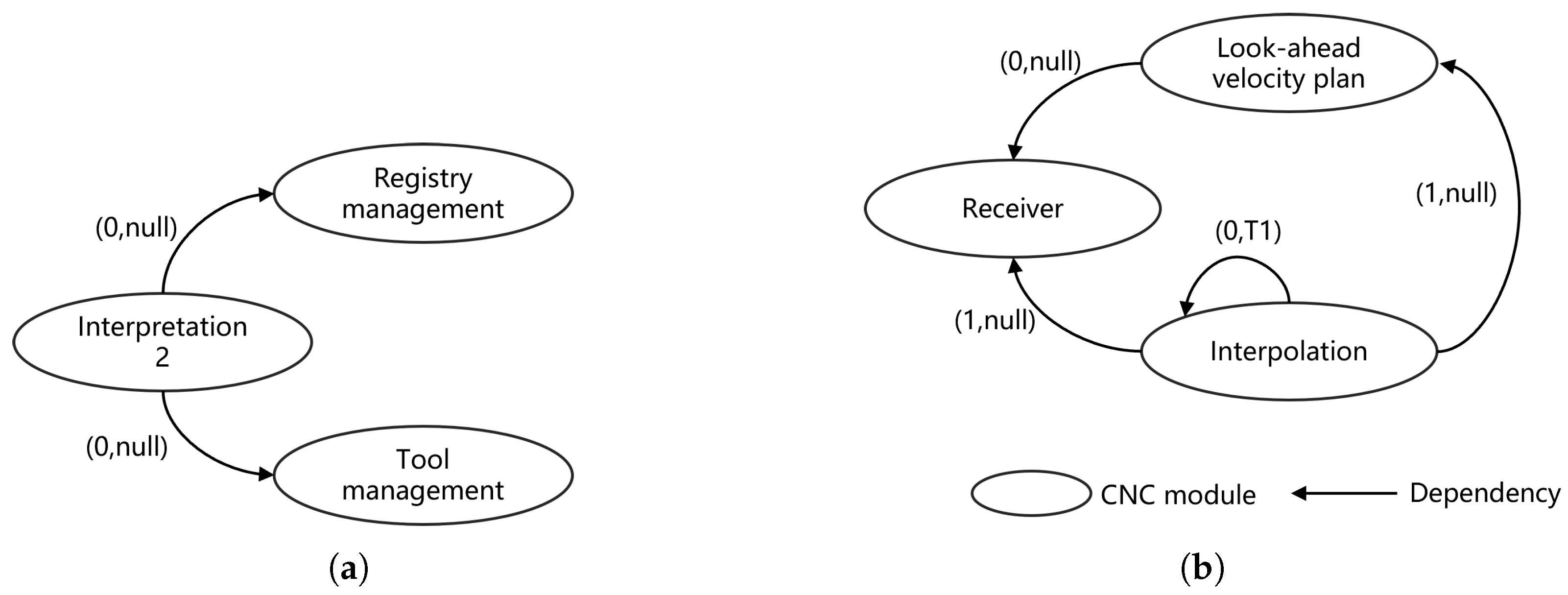
For the continuous behavior sub-domain, on the other hand, the dependency network model (DNM) is more suitable than the FSM for describing actions related to the states in Figure 7 and Figure 8. For example, in the Scheduling state in Figure 8, G/M codes are being translated, and this continuous process involves three CNC modules, as discussed in the case study in Section 3.2 and illustrated by the DNM in Figure 9a. The interpretation module depends on the registry management module to provide the machine-tool-level edge address and on the tool management module to provide tool information. Similarly, as shown in Figure 9b, the continuous process related to the Feeding state in Figure 8 also involves three CNC modules. The interpolation module has three dependencies: one on the look-ahead velocity plan module, one on the receiver module, and one on itself, which represents a self-dependency. The self-dependency means that the interpolation module executes cyclically. Each dependency is marked with a tuple ( p r i o r i t y , p e r i o d ) . It is clear that the priority of the self-dependency is lower than the priorities of the dependencies on the look-ahead velocity plan and receiver modules. The interpolation module runs at intervals of T 1 .
In summary, a primary challenge of reconfigurable architectures is providing a deterministic description of CNC functionality (or CNC domain knowledge). A CNC (control) domain-specific language (C-DSL) based on the FSM and the DNM offers a potential solution. Unlike current open CNC prototypes that adopt a modular approach and focus on defining standard granularity for CNC modules at the model level, this C-DSL operates at a meta-model level, concentrating on the dependency relationships and state transitions of CNC modules. This flexibility allows the granularity of CNC modules to vary according to user demands, enhancing the customizability of CNC systems. In a multi-user and multi-vendor context, this approach shifts the design of CNC systems from a vendor-driven to a user-driven model, enabling users to customize CNC functionality by using the C-DSL, while vendors provide the corresponding CNC modules to construct specific systems.

4.2. Decoupling of CNC Modules and Infrastructures

In the reconfigurable architecture, CNC modules, infrastructures, and machine tools represent three distinct and independent resource entities. Within this framework, the decoupling of CNC modules from infrastructures introduces a new challenge: how to construct infrastructure-independent CNC modules. Virtualizing CNC modules offers a potential solution to this challenge.
Virtualization technologies can be broadly classified into hypervisor-based and operating system (OS)-based approaches [25]. Hypervisor-based virtualization uses a hypervisor to abstract infrastructure resources and typically requires a complete guest OS to run software applications, as illustrated in Figure 10a. However, this approach introduces redundant overhead, as both the hypervisor and the guest OS provide isolation and resource abstraction. In contrast, container-based virtualization offers OS-level isolation by packaging a software application along with its dependencies (e.g., binaries, libraries, configuration files, and a base image) into a container, as shown in Figure 10b. A running container is essentially a process, but it operates with unique namespaces and control groups assigned by a container engine (e.g., Docker). Multiple containers share the host OS kernel. In summary, compared with hypervisors, container-based virtualization features smaller image sizes and faster instantiation times, but it provides weaker isolation and security.
Thus, while hypervisor-based virtualization is primarily focused on infrastructure-level abstraction, container-based virtualization is more aligned with application-level (or module-level) needs. In the context of the reconfigurable architecture, containers are more suitable to implement dynamic many-to-many relationships between CNC modules and infrastructure resources.
In recent years, containers have become increasingly attractive in industrial control systems. Reviews conducted in [26,27] indicate that containers can meet the real-time requirements of these systems, providing near-native performance alongside enhanced modularity, flexibility, and portability. However, there are concerns related to the optimal allocation of containers to resources, especially when multiple containers running real-time applications need to access shared resources. Furthermore, the portability of containers is conditional due to their reliance on the host OS kernel. For instance, the interpolation module depends on system calls from a real-time kernel (e.g., sched_setscheduler(), setitimer()) to ensure its periodic and deterministic execution.
Figure 10. Architectures of virtualization technologies [28]. (a) Hypervisor-based virtualization. (b) Container-based virtualization.
Machines 12 00793 g010
Another often-overlooked issue in current studies is that despite containers being a lightweight virtualization technology, container images may still be too large for deployment on machine-tool-level edges, especially when running multiple containers on such devices. For instance, as shown in Figure 5, three CNC modules are deployed on a machine-tool-level edge. In the case of containerization, each module would have its own base image, typically consisting of a minimal OS layer, which, even at its smallest, is around 100 MB. Although running containers can share the same base image, this base image still introduces redundancy compared with the host OS. Additionally, a container engine is required to deploy on this edge to manage the containers, as Figure 10b presents. Furthermore, the dependency among these three modules is intimate; for example, the look-ahead velocity plan module must generate a new velocity profile and send it to the interpolation module in response to feed override. Therefore, communication among them is implemented by using shared memory. While containers deployed on the same host OS can communicate via shared memory, the container isolation mechanisms (such as namespaces and control groups) introduce extra overhead, which can negatively affect deterministic execution and real-time performance.
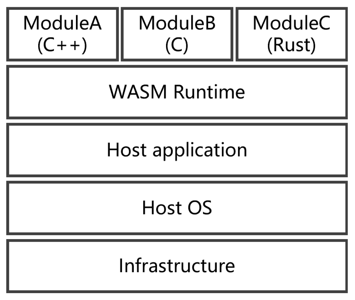
In contrast, WebAssembly (wasm) represents a fundamentally different approach to virtualization. Rather than functioning as a traditional virtualization technology, wasm is a compact binary bytecode format that serves as a compilation target for various programming languages, such as C, C++, and Rust. Originally, wasm was introduced by major browsers to complement JavaScript, allowing browsers to run native code efficiently in a fast, portable, and secure manner, making it suitable for complex and interactive web applications [29]. With the introduction of the WebAssembly System Interface (WASI), which defines a standardized set of interfaces and functionalities that abstract the underlying operating system, wasm modules have extended beyond browsers to other runtime environments (e.g., WARM and WasmEdge) [30,31]. This has broadened its applicability, allowing wasm to be used in a variety of non-browser environments, as depicted in Figure 11. In this architecture, the host application loads wasm runtime, which is responsible for loading and executing wasm modules. In this context, wasm provides a more lightweight and portable solution by compiling code to a uniform target, ideal for performance-critical applications, especially in constrained environments. Containers, while more flexible in terms of packaging entire environments, come with a higher overhead and are more suited to scenarios where modularity and environmental consistency are critical.
However, there are some challenges with wasm-based CNC module virtualization. First and foremost, not all programming languages can currently be compiled into wasm modules. For instance, Python, which is widely used in various fields (such as LinuxCNC [32], which is developed using Python, C, and other languages), presents a challenge. Unlike languages like C/C++, which are typically compiled into machine code, Python is an interpreted language. This means that Python relies on an interpreter for execution, making it difficult to compile directly into a wasm module, as wasm was originally designed with compiled languages in mind. While there are ongoing efforts, such as projects aimed at compiling Python into wasm, the performance and compatibility of these solutions still fall short compared with natively compiled languages.
Moreover, similar to containers, the portability of wasm modules has limitations. CNC modules that rely on system calls—particularly real-time API calls—often cannot be compiled into wasm modules, as the WebAssembly System Interface (WASI) currently lacks support for these APIs. In summary, wasm is better suited for virtualizing computation-intensive CNC modules, while those with heavy I/O or real-time dependencies may face challenges.
A proposed solution was designed and tested for CNC modules, as shown in Figure 5. In this setup, three modules are deployed on the machine-tool-level edge: the receiver module, which is I/O-intensive; the look-ahead velocity planning module, which is computation-intensive; and the interpolation module, which is both I/O- and computation-intensive. For the test, the receiver module was implemented in Python, while the other two modules were written in C/C++. The look-ahead velocity planning module was compiled into a wasm module, whereas the other two were compiled as the host application. Figure 12 presents the log of the execution of these three CNC modules, where the G/M codes from Figure 8 are used as input, interpreted by the interpretation module developed in the author’s previous work [33,34]. It is evident that the velocity planning wasm module, rather than being infrastructure-dependent, is host-application-dependent. This is akin to Java’s “write once, run anywhere” model, where Java applications run as long as a Java Virtual Machine (JVM) is available. Similarly, the velocity planning wasm module can run anywhere as long as the corresponding host application is available. Moreover, this also allows the host application to dynamically load another wasm module with a different velocity planning algorithm if needed.
In summary, dynamically deploying CNC modules on infrastructure resources to maximize resource utilization and ensure deterministic execution presents another challenge—the need to decouple CNC modules from the underlying infrastructure. Virtualization technologies, such as containers and WebAssembly, offer potential solutions to this problem. However, as discussed above, achieving the complete decoupling of CNC modules from the infrastructure remains impossible with current technologies, particularly for CNC modules with high time sensitivity.

4.3. Management of CNC Modules, Infrastructures, and Machine Tools

The third challenge of the reconfigurable architecture is the management of CNC modules, infrastructures, and machine tools. This involves enabling the dynamic interaction among these three independent resources to rapidly, economically, and sustainably adapt to various production requirements. As discussed in Section 3.3, this dynamic, many-to-many interaction not only occurs among these resources but also between users and vendors.
To address this challenge, the platformization of CNC systems is emerging as a promising trend, potentially leading to an ecosystem-based approach for CNC systems. Specifically, a platform is proposed to decouple users from vendors, connecting them indirectly while also integrating CNC modules, infrastructures, and machine tools. Through this platform, users can customize CNC functionality by using the domain-specific language provided by the platform (related to the first challenge) and publish their requirements. Additionally, users can publish their infrastructures and machine tools on the platform and manage them, such as equipping machine tools with CNC functionality. Vendors, in turn, publish CNC modules and infrastructures that align with users’ needs. CNC modules are developed in a standardized form defined by the platform (related to the second challenge), such as through containerization or WebAssembly modules. Therefore, it becomes clear that this challenge is fundamentally built on the successful implementation of the first two challenges.
In summary, the first two challenges aim to establish CNC modules, infrastructures, and machine tools as three independent resources. Once this is achieved, the third challenge centers on effectively managing these resources. A platform-oriented operational model offers a potential solution. In this model, the functionality of the reconfigurable architecture extends beyond traditional CNC functionality to also include platform functionality, with the CNC functionality built upon the platform’s capabilities. Therefore, analyzing both the functional and non-functional requirements of the platform is crucial for its successful construction.

5. Conclusions and Future Work

By decoupling the domains of control, infrastructure, and actuator into independent resources, this paper proposes a reconfigurable architecture that facilitates the construction of control systems across control, infrastructure, and actuator planes. Compared with traditional open and networked architectures, this approach enables two dynamic many-to-many relationships: one among these distinct resources and the other between users and vendors.
Three key challenges are summarized, along with potential solutions, as follows:
  • Deterministic description of control functionality: Defining a standard granularity for control modules is challenging, and the commonly used FSM-based behavior model is more suited for discrete behaviors. To address this, a hybrid semantic model combining the FSM and the DNM is proposed. The DNM is used to describe continuous behaviors, allowing the development of a C-DSL that emphasizes the dependency relationships among control modules rather than fixed granularity.
  • Decoupling of control modules and infrastructures: Achieving independence for control modules requires their isolation from underlying infrastructures. Virtualization technologies provide a viable solution, with OS-level virtualization being more suitable for this reconfigurable architecture. WebAssembly complements container-based virtualization for virtualizing control modules. However, it is acknowledged that currently, not all control modules can be entirely decoupled from their infrastructures.
  • Management of control modules, infrastructures, and actuators: A platform-oriented operation model is proposed, extending the functionality of the reconfigurable architecture beyond mere control functionality. It is noted that addressing this challenge is interconnected with the solutions to the first two challenges.
Overall, the proposed reconfigurable architecture shifts the design of industrial control systems from reliance on vendors providing generic, often redundant systems to a user-centric, customized approach. Users can define control functionality by using the C-DSL and publish it on the platform, allowing vendors to bid on this functionality and provide suitable control modules.
However, the reconfigurable architecture faces additional key issues that will be addressed in the future:
  • The proposed methods for the first two challenges primarily focus on core functional issues while overlooking non-functional aspects. For instance, the construction of a C-DSL as a declarative language requires the definition of its lexical and syntactic specifications. Moreover, the feasibility of the control functionality described by the C-DSL must be verified according to these specifications.
  • The backward compatibility issue poses a challenge for traditional control systems with closed architectures and stand-alone operation models. It may be difficult to utilize these systems as intended in the reconfigurable architecture—decoupling control software into independent control modules and from underlying infrastructures. Instead, these legacy systems could be restructured as a whole into an independent resource, serving as a transitional step towards a user-centric operation model.
  • Finally, the development of the platform itself is crucial. Solutions to all the aforementioned challenges need to be integrated into the platform as its core functional properties, making platform development a vital aspect of the reconfigurable architecture.

Author Contributions

Conceptualization, L.L. and X.Q.; methodology, L.L.; investigation, L.L. and Z.X.; writing—original draft preparation, L.L.; writing—review and editing, X.Q.; funding acquisition, L.L. All authors have read and agreed to the published version of the manuscript.

Funding

This research study was funded by the Science, Technology and Innovation Commission of Shenzhen Municipality (No. 20220809175919001).

Data Availability Statement

Data are contained within the article.

Conflicts of Interest

Author Xiaobin Qu was employed by the company China Nuclear Power Technology Research Institute Co., Ltd. The remaining authors declare that the research was conducted in the absence of any commercial or financial relationships that could be construed as a potential conflict of interest.

References

  1. Mantravadi, S.; Møller, C.; Chen, L.I.; Schnyder, R. Design Choices for Next-Generation IIoT-Connected MES/MOM: An Empirical Study on Smart Factories. Robot. Comput.-Integr. Manuf. 2022, 73, 102225. [Google Scholar] [CrossRef]
  2. Givehchi, M.; Liu, Y.; Wang, X.V.; Wang, L. Function Block-enabled Operation Planning And Machine Control in Cloud-DPP. Int. J. Prod. Res. 2002, 61, 1168–1184. [Google Scholar] [CrossRef]
  3. Liu, C.; Su, Z.; Xu, X.; Lu, Y. Service-Oriented Industrial Internet of Things Gateway for Cloud Manufacturing. Robot. Comput.-Integr. Manuf. 2022, 73, 102217. [Google Scholar] [CrossRef]
  4. Wang, L.-C.; Chen, C.-C.; Liu, J.-L.; Chu, P.-C. Framework and Deployment of a Cloud-based Advanced Planning and Scheduling System. Robot. Comput.-Integr. Manuf. 2021, 70, 102088. [Google Scholar] [CrossRef]
  5. Yang, H.; Ong, S.K.; Nee, C.; Jiang, G.; Mei, X. Microservices-based Cloud-edge Collaborative Condition Monitoring Platform for Smart Manufacturing Systems. Int. J. Prod. Res. 2022, 60, 7492–7501. [Google Scholar] [CrossRef]
  6. Yu, H.; Yu, D.; Wang, C.; Hu, Y.; Li, Y. Edge Intelligence-driven Digital Twin of CNC System: Architecture and Deployment. Robot. Comput.-Integr. Manuf. 2023, 79, 102418. [Google Scholar] [CrossRef]
  7. Kalyvas, M. An Innovative Industrial Control System Architecture for Real-time Response, Fault-tolerant Operation and Seamless Plant Integration. J. Eng. 2021, 2021, 569–581. [Google Scholar] [CrossRef]
  8. Suh, S.-H.; Kang, S.K.; Chung, D.-H.; Stroud, I. Theory and Design of CNC Systems; Springer: London, UK, 2008. [Google Scholar]
  9. Pritschow, G.; Altintas, Y.; Jovane, F.; Koren, Y.; Mitsuishi, M.; Takata, S.; Van Brussel, H.; Weck, M.; Yamazaki, K. Open Controller Architecture—Past, Present and Future. CIRP Ann. 2001, 50, 463–470. [Google Scholar] [CrossRef]
  10. Michaloski, J.; Birla, S.; Yen, C.J.; Igou, R.; Weinert, G. An Open System Framework for Component-Based CNC Machines. ACM Comput. Surv. 2000, 32, 23. [Google Scholar] [CrossRef]
  11. Michaloski, J. Analysis of Module Interaction in an OMAC Controller. In Proceedings of the World Automation Congress Conference, Maui, HI, USA, 11–16 June 2000. [Google Scholar]
  12. Wei, H.; Duan, X.; Chen, Y.; Zhang, X. Research on Open CNC System Based on CORBA. In Proceedings of the Fifth IEEE International Symposium on Embedded Computing, Beijing, China, 6–8 October 2008. [Google Scholar]
  13. Ma, X.; Han, Z.; Wang, Y.; Fu, H. Development of a PC-based Open Architecture Software-CNC System. Chin. J. Aeronaut. 2007, 20, 272–281. [Google Scholar] [CrossRef]
  14. Minhat, M.; Vyatkin, V.; Xu, X.; Wong, S.; Al-Bayaa, Z. A Novel Open CNC Architecture Based on STEP-NC Data Model and IEC 61499 Function Blocks. Robot. Comput.-Integr. Manuf. 2009, 25, 560–569. [Google Scholar] [CrossRef]
  15. Harbs, E.; Negri, G.H.; Jarentchuk, G.; Hasegawa, A.Y.; Rosso, R.S.U., Jr.; da Silva Hounsell, M.; Lafratta, F.H.; Ferreira, J.C. CNC-C2: An ISO14649 and IEC61499 Compliant Controller. Int. J. Comput. Integr. Manuf. 2021, 34, 621–640. [Google Scholar] [CrossRef]
  16. Park, S.; Kim, S.-H.; Cho, H. Kernel Software for Efficiently Building, Re-configuring, and Distributing an Open CNC Controller. Int. J. Adv. Manuf. Technol. 2005, 27, 788–796. [Google Scholar] [CrossRef]
  17. Wang, T.; Wang, L.; Liu, Q. A Three-ply Reconfigurable CNC System Based on FPGA and Field-bus. Int. J. Adv. Manuf. Technol. 2011, 57, 671–682. [Google Scholar] [CrossRef]
  18. Liu, L.; Yao, Y.; Li, J. A Review of the Application of Component-based Software Development in Open CNC Systems. Int. J. Adv. Manuf. Technol. 2020, 107, 3727–3753. [Google Scholar] [CrossRef]
  19. Givehchi, O.; Imtiaz, J.; Trsek, H.; Jasperneite, J. Control-as-a-Service from the Cloud: A Case Study for Using Virtualized PLCs. In Proceedings of the 10th IEEE Workshop on Factory Communication Systems, Toulouse, France, 5–7 May 2014. [Google Scholar]
  20. Sang, Z.; Xu, X. The Framework of a Cloud-based CNC System. Procedia CIRP 2017, 63, 82–88. [Google Scholar] [CrossRef]
  21. Bigheti, J.A.; Fernandes, M.M.; Godoy, E.P. Control as a Service: A Microservice Approach to Industry 4.0. In Proceedings of the II Workshop on Metrology for Industri 4.0 and IoT, Naples, Italy, 4–6 June 2019. [Google Scholar]
  22. Cruz, T.; Simoes, P.; Monteiro, E. Virtualizing Programmable Logic Controllers: Toward a Convergent Approach. IEEE Embed. Syst. Lett. 2016, 8, 69–72. [Google Scholar] [CrossRef]
  23. Gupta, R.A.; Chow, M.-Y. Networked Control System: Overview and Research Trends. IEEE Trans. Ind. Electron. 2010, 57, 2527–2535. [Google Scholar] [CrossRef]
  24. Zhang, X.-M.; Han, Q.-L.; Ge, X.; Ding, D.; Ding, L.; Yue, D.; Peng, C. Networked Control Systems: A Survey of Trends and Techniques. IEEE/CAA J. Autom. Sin. 2020, 7, 1–17. [Google Scholar] [CrossRef]
  25. Morabito, R.; Kjällman, J.; Komu, M. Hypervisors vs. Lightweight Virtualization: A Performance Comparison. In Proceedings of the IEEE International Conference on Cloud Engineering, Tempe, AZ, USA, 9–13 March 2015. [Google Scholar]
  26. Queiroz, R.; Cruz, T.; Mendes, J.; Sousa, P.; Simões, P. Container-based Virtualization for Real-Time Industrial Systems—A Systematic Review. ACM Comput. Surv. 2023, 56, 1–38. [Google Scholar] [CrossRef]
  27. Struhár, V.; Behnam, M.; Ashjaei, M.; Papadopoulos, A.V. Real-time Containers: A Survey. Open Access Ser. Inform. 2020, 80, 7:1–7:9. [Google Scholar]
  28. Mansouri, Y.; Babar, M.A. A Review of Edge Computing: Features and Resource Virtualization. J. Parallel Distrib. Comput. 2021, 150, 155–183. [Google Scholar] [CrossRef]
  29. Haas, A.; Rossberg, A.; Schuff, D.L.; Titzer, B.L.; Holman, M.; Gohman, D.; Wagner, L.; Zakai, A.; Bastien, J.F. Bringing the Web Up to Speed with WebAssembly. In Proceedings of the 38th ACM SIGPLAN Conference on Programming Language Design and Implementation—PLDI 2017, Barcelona, Spain, 18–23 June 2017. [Google Scholar]
  30. Ray, P.P. An Overview of WebAssembly for IoT: Background, Tools, State-of-the-Art, Challenges, and Future Directions. Future Internet 2023, 15, 275. [Google Scholar] [CrossRef]
  31. Wallentowitz, S.; Kersting, B.; Dumitriu, D.M. Potential of WebAssembly for Embedded Systems. In Proceedings of the 11th Mediterranean Conference on Embedded Computing (MECO), Budva, Montenegro, 7–10 June 2022. [Google Scholar]
  32. LinuxCNC. Available online: https://linuxcnc.org/ (accessed on 23 September 2024).
  33. Liu, L.; Yao, Y.; Du, J. A Universal and Scalable CNC Interpreter for CNC Systems. Int. J. Adv. Manuf. Technol. 2019, 103, 4453–4466. [Google Scholar] [CrossRef]
  34. Liu, L.; Yao, Y. Development of a CNC Interpretation Service with Good Performance and Variable Functionality. Int. Comput. Integr. Manuf. 2022, 35, 725–742. [Google Scholar] [CrossRef]
Figure 1. Status quo of industrial IoT via mapping to ISA-95 model.
Machines 12 00793 g001
Figure 2. Criteria of open-architecture systems [9].
Machines 12 00793 g002
Figure 3. Three planes of the reconfigurable architecture.
Machines 12 00793 g003
Figure 4. Main CNC modules in NCK.
Machines 12 00793 g004
Figure 5. Reconfigured NCK.
Machines 12 00793 g005
Figure 6. Execution sequence of reconfigured NCK.
Machines 12 00793 g006
Figure 7. FSM-based description of overall CNC functionality.
Machines 12 00793 g007
Figure 8. FSM graph of Auto state.
Machines 12 00793 g008
Figure 9. Continuous behaviors described by dependency network model. (a) Continuous process relates to the Paused state. (b) Continuous process relates to the Feeding state.
Machines 12 00793 g009
Figure 11. Architecture of wasm-based applications.
Machines 12 00793 g011
Figure 12. Log of execution of CNC modules.
Machines 12 00793 g012
Disclaimer/Publisher’s Note: The statements, opinions and data contained in all publications are solely those of the individual author(s) and contributor(s) and not of MDPI and/or the editor(s). MDPI and/or the editor(s) disclaim responsibility for any injury to people or property resulting from any ideas, methods, instructions or products referred to in the content.