
Modeling and Characteristic Test for a Crank-Connecting Rod Mem-Inerter Device


Abstract
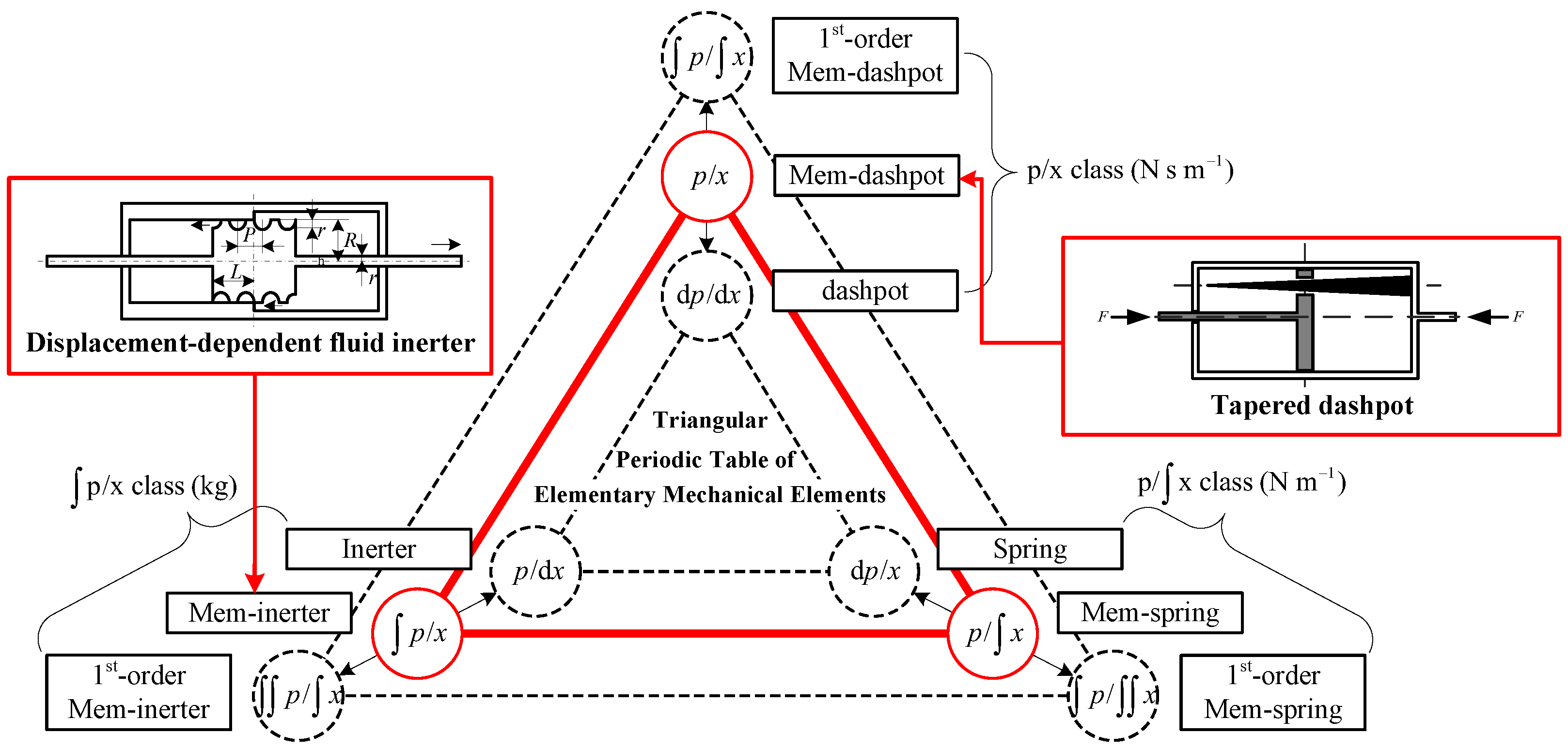
:1. Introduction
2. Crank-Connecting Rod Mem-Inerter Device
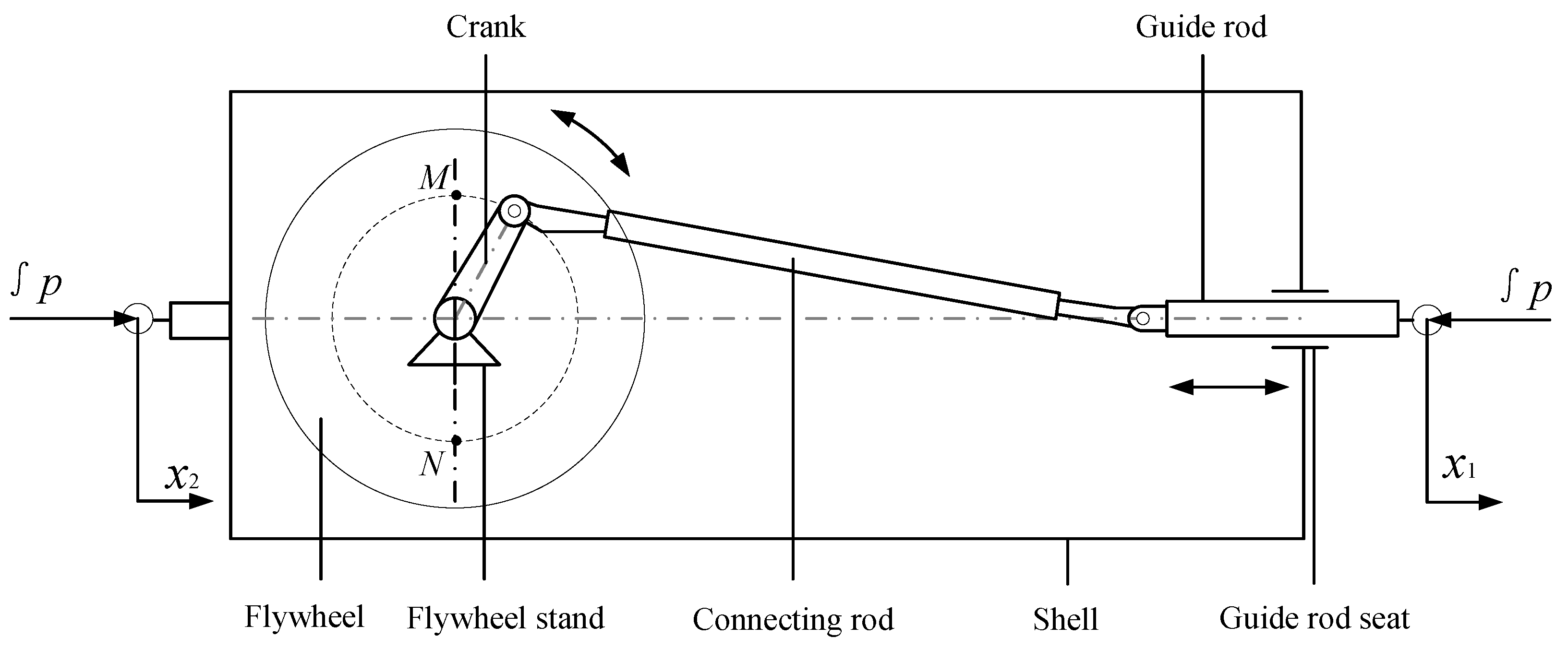
2.1. Structural Design and Working Principle
2.2. Modeling
2.2.1. Model Assumptions
- The mass distribution of the flywheel is uniform and its moment of inertia always remains constant;
- The crank-connecting rod mechanism is tightly connected and sufficiently rigid, without any gaps or deformations and the inertance of the device is not affected by the mass of the mechanism itself;
- The indirect contact surfaces of each component of the device are smooth and the frictional resistance can be ignored.
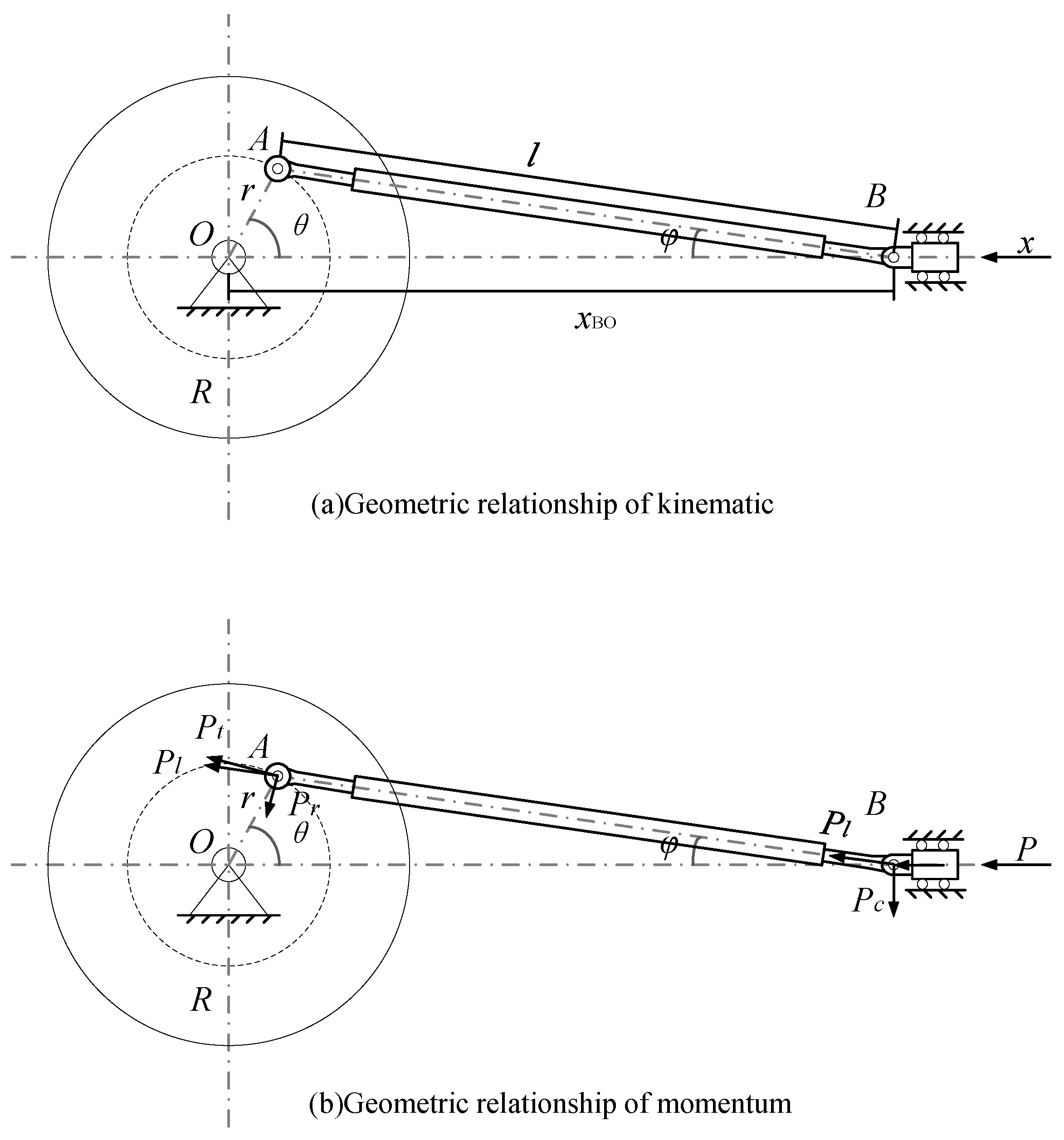
2.2.2. Mathematics Modeling
2.3. Characteristic Analysis
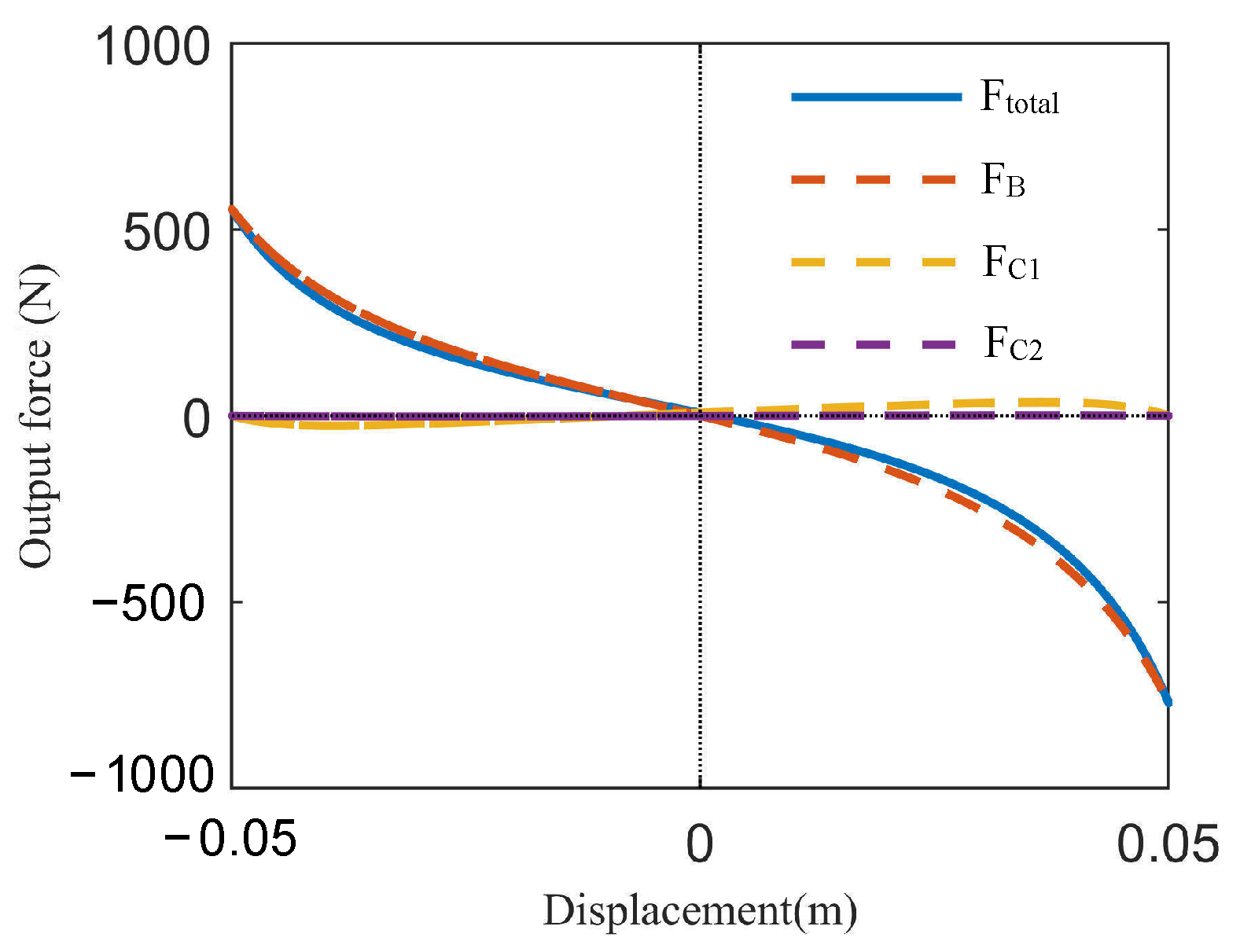
2.3.1. Output Force Characteristics
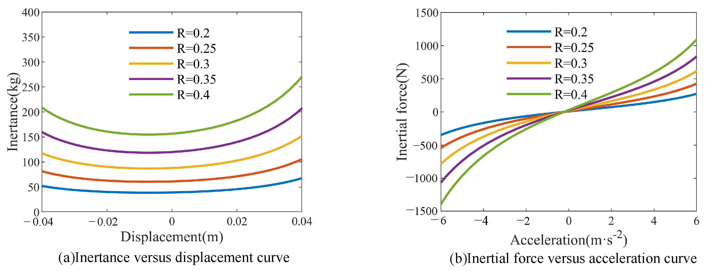
2.3.2. Structural Parameter Characteristics
- (1)
- Flywheel radius R
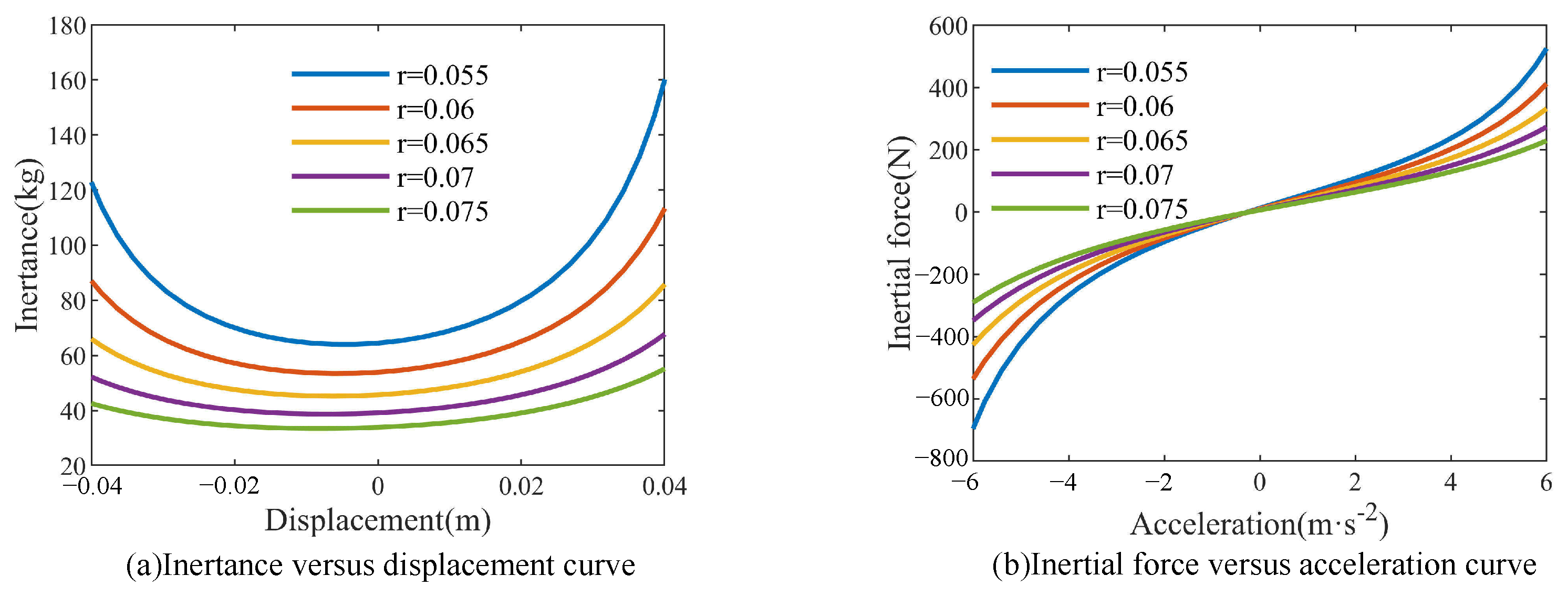
- (2)
- Crank length r
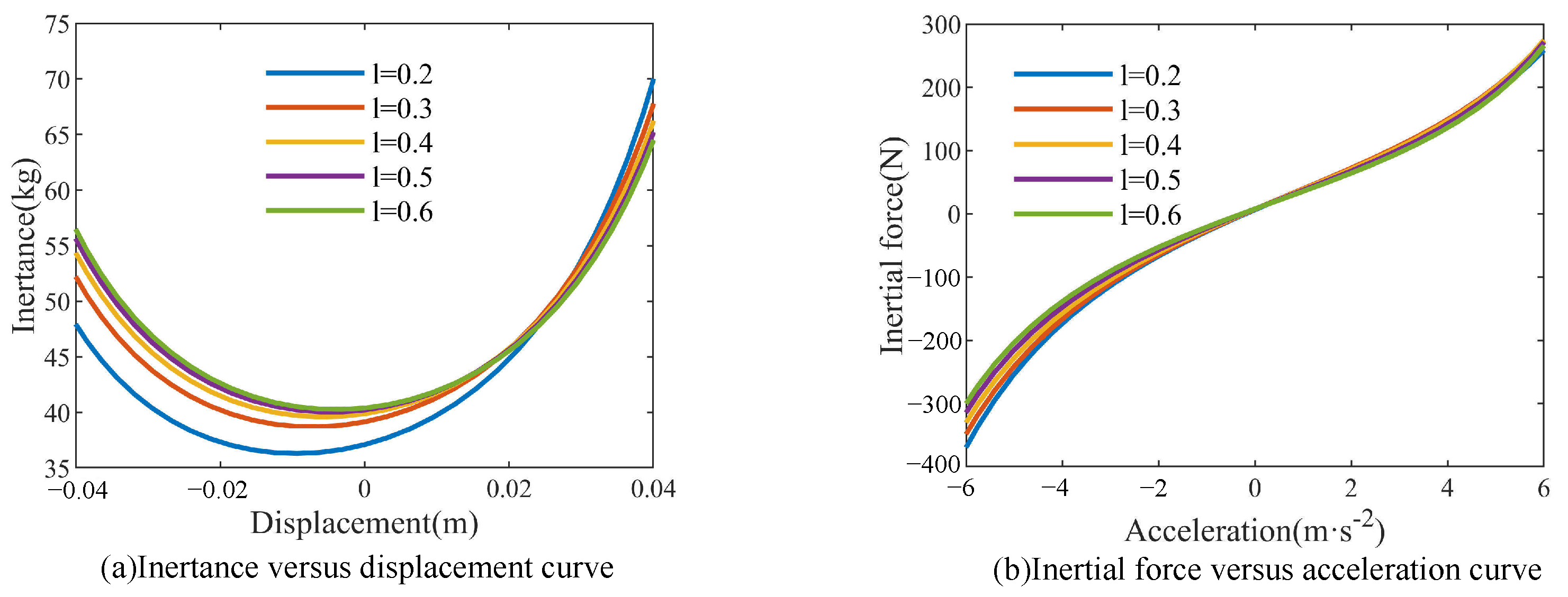
- (3)
- Connecting rod length l
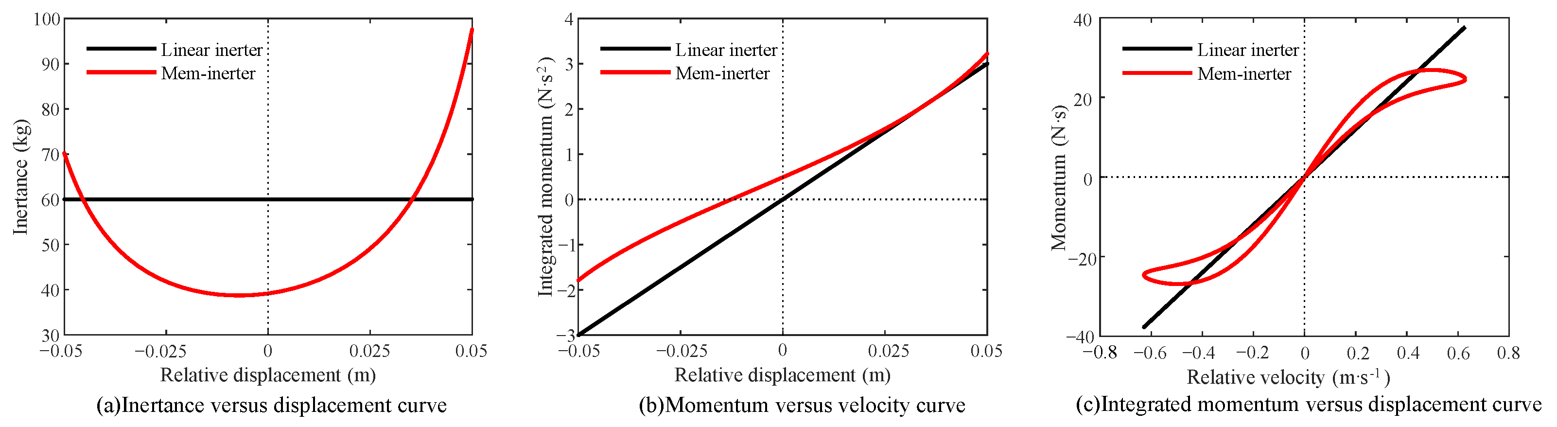
2.3.3. Memory Characteristics
3. Bench Test
3.1. Engineering Model
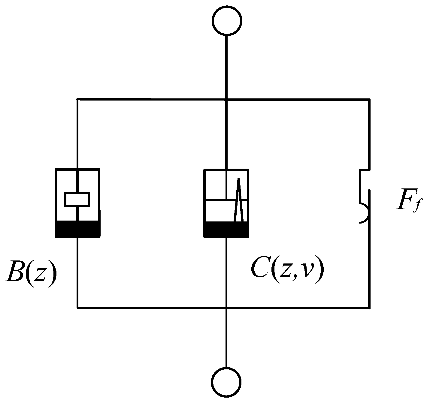
3.1.1. Dry Friction Model
3.1.2. Parasitic Damping Model
3.2. Prototype Trial Production
3.3. Characteristic Test of Mem-Inerter Device
3.3.1. Triangular Wave Input Quasi-Static Test
3.3.2. Sine Wave Input Dynamic Characteristics Test
3.3.3. Signal Acquisition
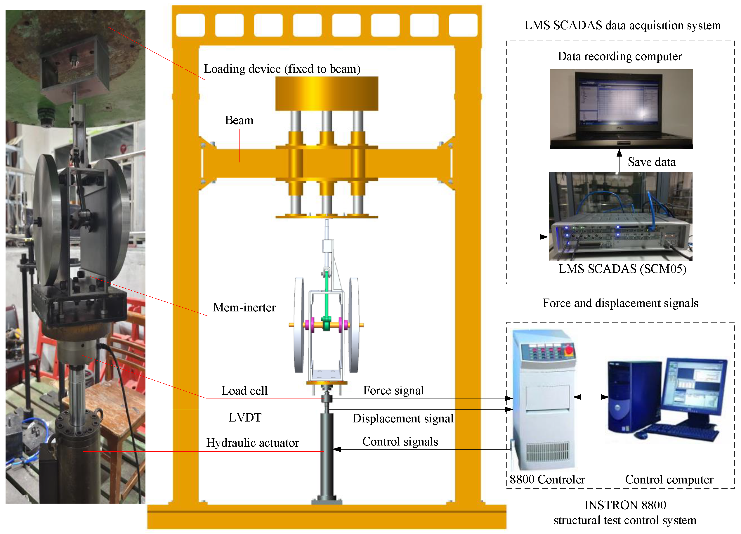
3.4. Working Principle and Layout Installation of the Test Bench
4. Experimental Results and Analysis
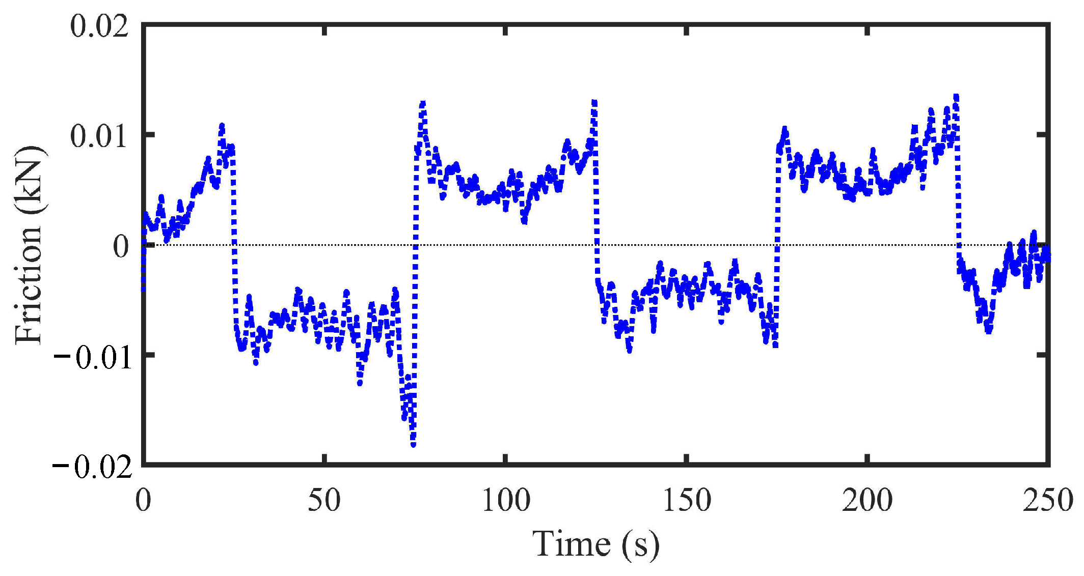
4.1. Dry Friction Separation
4.2. Characteristic Analysis of Mem-Inerter
5. Conclusions
- Firstly, the research established a mathematical model for the proposed device and derived its inertance expression and constitutive relation. The findings indicated the characteristic curve on the momentum–velocity plane, displaying a pinched hysteresis loop. On the integrated momentum–displacement plane, a one-to-one correspondence relationship was observed, which served as evidence for the memory characteristics of the crank-connecting rod inerter. Therefore, it was classified as a displacement-dependent mem-inerter.
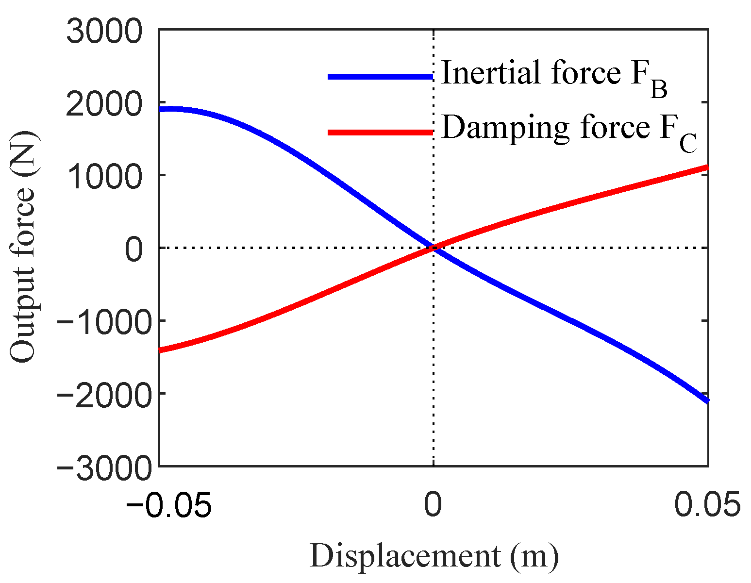
- Secondly, this study established a practical engineering model for the crank-connecting rod mem-inerter, and a prototype of the trial production device was successfully developed. The results of the simulation and the bench test indicated that the damping force constituted a relatively small proportion of the mem-inerter’s output force. Quasi-static tests further confirmed the device’s low frictional resistance. Consequently, the parasitic damping and frictional resistance could be disregarded.
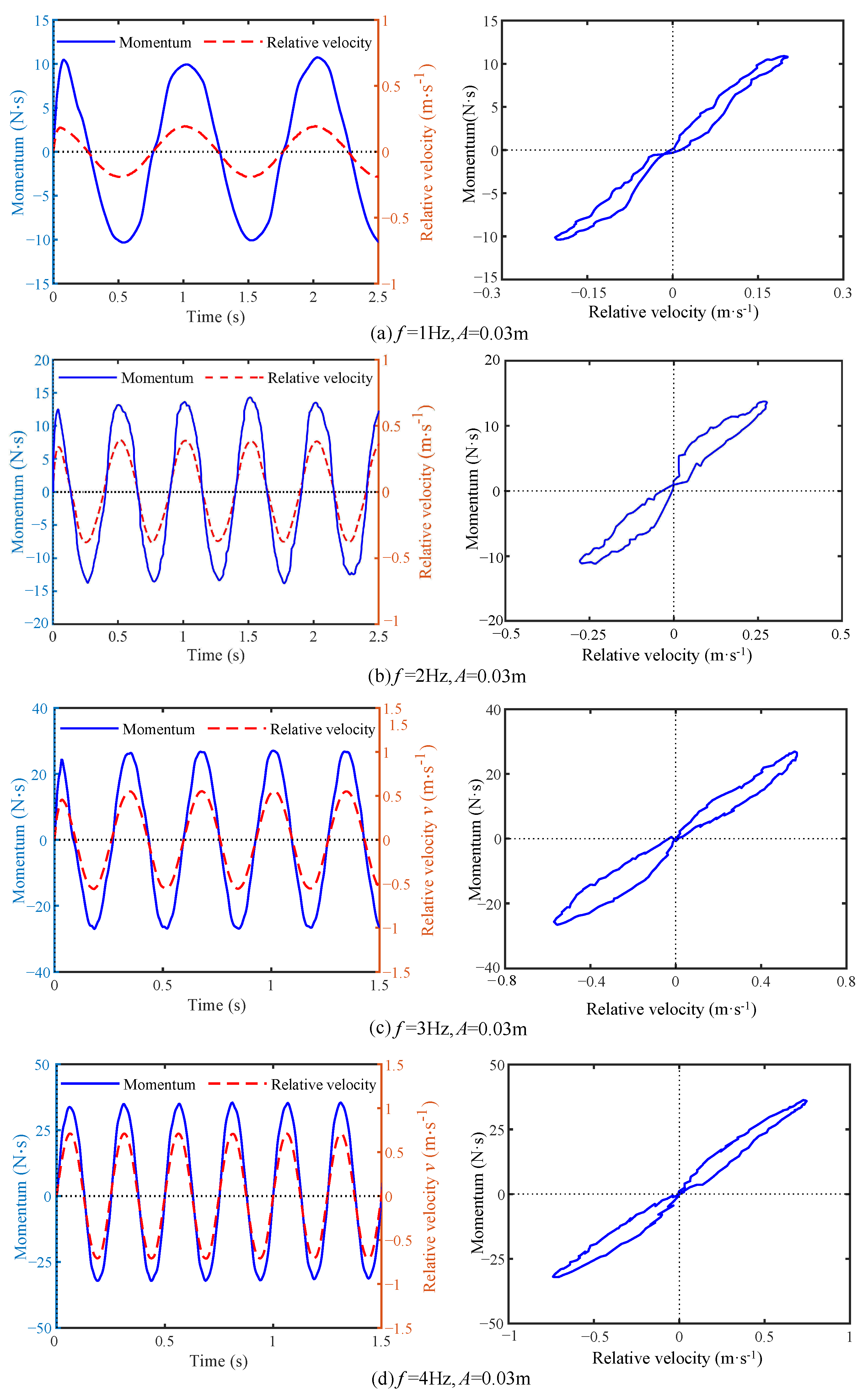
- Thirdly, the dynamic characteristic test results demonstrated consistent pinched hysteresis loop characteristic curves on the momentum–velocity plane at various frequencies. Notably, the time domain curves of momentum and velocity intersected the time axis, providing conclusive evidence that the proposed device serves as an ideal physical realization of a mem-inerter.
Author Contributions
Funding
Data Availability Statement
Conflicts of Interest
References
- Smith, M. Synthesis of mechanical networks: The inerter. IEEE Trans. Autom. Control 2002, 47, 1648–1662. [Google Scholar] [CrossRef]
- Ma, R.; Bi, K.; Zuo, H.; Du, X. Inerter-based damping isolation system for vibration control of offshore platforms subjected to ground motions. Ocean. Eng. 2023, 280, 114726. [Google Scholar] [CrossRef]
- Garrido, H.; Domizio, M.; Curadelli, O.; Ambrosini, D. Inerter-based Building Mass Damper: Optimization and experimental study. Eng. Struct. 2024, 301, 117277. [Google Scholar] [CrossRef]
- Ul Islam, N.; Jangid, R.S. Negative stiffness and inerter-based dampers: Novel seismic response control approach for base isolated liquid storage tanks. Structures 2024, 60, 105860. [Google Scholar] [CrossRef]
- Li, H.; Bi, K.; Hao, H. Effect of negative stiffness nonlinearity on the vibration control effectiveness of tuned negative stiffness inerter damper. Eng. Struct. 2023, 293, 116641. [Google Scholar] [CrossRef]
- Wang, Y.; Xu, B.; Meng, H. Enhanced vehicle shimmy performance using inerter-based suppression mechanism. Commun. Nonlinear Sci. Numer. Simul. 2024, 130, 107800. [Google Scholar] [CrossRef]
- Ma, R.; Bi, K.; Hao, H. Inerter-based structural vibration control: A state-of-the-art review. Eng. Struct. 2021, 243, 112655. [Google Scholar] [CrossRef]
- Song, J.; Bi, K.; Ma, R.; Wang, Z.; Xu, K.; Hao, H. Vibration control of adjacent structures equipped with inerter-based dampers considering nonlinearities: Analytical and experimental studies. Mech. Syst. Signal Process. 2024, 206, 110903. [Google Scholar] [CrossRef]
- Chowdhury, S.; Banerjee, A.; Adhikari, S. The optimal configuration of negative stiffness inerter-based base isolators in multi-storey buildings. Structures 2023, 50, 1232–1251. [Google Scholar] [CrossRef]
- Zhang, R.; Zhao, Z.; Pan, C.; Ikago, K.; Xue, S. Damping enhancement principle of inerter system. Struct. Control Health Monit. 2020, 27, e2523. [Google Scholar] [CrossRef]
- Yang, X.; He, T.; Shen, Y.; Liu, Y.; Yan, L. Research on predictive coordinated control of ride comfort and road friendliness for heavy vehicle ISD suspension based on the hybrid-hook damping strategy. Proc. Inst. Mech. Eng. Part D-J. Automob. Eng. 2024, 238, 443–456. [Google Scholar] [CrossRef]
- Zhang, X.L.; Zhu, J.; Nie, J.; Gene Liao, Y.; Lu, X. Analysis of inertance and damping double-skyhook control strategies for a semi-active device combining an adjustable inerter and damper. Struct. Control Health Monit. 2022, 29, e3040. [Google Scholar] [CrossRef]
- Wang, Y.; Xu, B.; Chen, W.; Meng, H. Vehicle shimmy performance analysis using inerter-based suppression mechanism and considering steering linkage clearance. Int. J. Non-Linear Mech. 2024, 161, 104674. [Google Scholar] [CrossRef]
- Szczyglowski, C.P.; Neild, S.A.; Titurus, B.; Jiang, J.Z.; Coetzee, E. Passive Gust Loads Alleviation in a Truss-Braced Wing Using an Inerter-Based Device. J. Aircr. 2019, 56, 2260–2271. [Google Scholar] [CrossRef]
- May, P.; Li, H.; Yang, H.T. Inerter-Based Eigenvector Orientation Approach for Passive Control of Supersonic Panel Flutter. Mathematics 2023, 11, 1462. [Google Scholar] [CrossRef]
- Liu, Y.; Liu, D.; Yang, Z.; Ding, Y. Dynamic model and performance assessment of inter-story isolation system with supplement inerter (IISI). Structures 2024, 70, 107781. [Google Scholar] [CrossRef]
- Yue, Z.; Han, G. Multi-objective optimal design of Tuned Mass Damper Inerter for base isolated structures. Sci. Rep. 2024, 14, 26370. [Google Scholar] [CrossRef]
- Shen, W.; Sun, Z.; Hu, Y.; Cai, L.; Zhu, H.; Silva, S. Energy harvesting performance of an inerter-based electromagnetic damper with application to stay cables. Mech. Syst. Signal Process. 2022, 170, 108790. [Google Scholar] [CrossRef]
- Kang, X.; Huang, Q.; Wu, Z.; Tang, J.; Jiang, X.; Lei, S. A Review of the Tuned Mass Damper Inerter (TMDI) in Energy Harvesting and Vibration Control: Designs, Analysis and Applications. CMES-Comput. Model. Eng. Sci. 2024, 139, 2361–2398. [Google Scholar] [CrossRef]
- Wagg, D.J. A review of the mechanical inerter: Historical context, physical realisations and nonlinear applications. Nonlinear Dyn. 2021, 104, 13–34. [Google Scholar] [CrossRef]
- Smith, M.; Wang, F. Performance benefits in passive vehicle suspensions employing inerters. Veh. Syst. Dyn. 2004, 42, 235–257. [Google Scholar] [CrossRef]
- Saito, K. Dynamic loading test and application to a high-rise building of viscous damping devices with amplification system. In Proceedings of the Third World Conference on Structural Control, Como, Italy, 7–12 April 2002. [Google Scholar] [CrossRef]
- Ikago, K.; Saito, K.; Inoue, N. Seismic control of single-degree-of-freedom structure using tuned viscous mass damper. Earthq. Eng. Struct. Dyn. 2012, 41, 453–474. [Google Scholar] [CrossRef]
- Ikago, K.; Sugimura, Y.; Saito, K.; Inoue, N. Optimum Seismic Response Control of Multiple Degree of Freedom Structures using Tuned Viscous Mass Dampers. In Proceedings of the Tenth International Conference on Computational Structures Technology, Valencia, Spain, 14–17 September 2010; Topping, B., Adam, J., Pallares, F., Bru, R., Romero, M., Eds.; Civil-Comp Press: Stirlingshire, UK, 2010; Volume 93. [Google Scholar] [CrossRef]
- Wang, F.C.; Hong, M.F.; Lin, T.C. Designing and testing a hydraulic inerter. Proc. Inst. Mech. Eng. Part C-J. Mech. Eng. Sci. 2011, 225, 66–72. [Google Scholar] [CrossRef]
- Zhan, Q.; Chen, Y.; Zhao, Y.; Chen, M.; Guo, R. Vibration suppressing study of a simplified floating raft system by mixing using a nonlinear connecting intercalary plate and connecting nonlinear oscillators. Thin-Walled Struct. 2025, 206, 112686. [Google Scholar] [CrossRef]
- Dai, W.; Li, T.; Wang, L.; Zhu, X.; Shi, B.; Yang, J. Performance enhancement of floating raft system by exploiting geometric nonlinearity and motion constraint in vibration isolators. Ocean. Eng. 2024, 314, 119656. [Google Scholar] [CrossRef]
- Nie, J.; Zhao, Y.; Zhang, X.; Zhang, T. Design and test of lateral interconnected hydro-pneumatic ISD suspension. Proc. Inst. Mech. Eng. Part D-J. Automob. Eng. 2024, 238, 633–645. [Google Scholar] [CrossRef]
- Chua, L. Memristor-The missing circuit element. IEEE Trans. Circuit Theory 1971, 18, 507–519. [Google Scholar] [CrossRef]
- Chua, L.O.; Kang, S.M. Memristive devices and systems. Proc. IEEE 1976, 64, 209–223. [Google Scholar] [CrossRef]
- Di Ventra, M.; Pershin, Y.V.; Chua, L.O. Circuit Elements with Memory: Memristors, Memcapacitors, and Meminductors. Proc. IEEE 2009, 97, 1717–1724. [Google Scholar] [CrossRef]
- Oster, G.F.; Auslander, D.M. The memristor: A new bond graph element. J. Dyn. Syst. Meas. Control 1972, 94, 249–252. [Google Scholar] [CrossRef]
- Jeltsema, D.; Doria-Cerezo, A. Port-Hamiltonian Formulation of Systems With Memory. Proc. IEEE 2012, 100, 1928–1937. [Google Scholar] [CrossRef]
- Biolek, D.; Biolek, Z.; Biolkova, V. Memristors and Other Higher-Order Elements in Generalized Through-Across Domain. In Proceedings of the 23rd IEEE International Conference on Electronics Circuits and Systems (ICECS 2016), Monte Carlo, Monaco, 11–14 December 2016; pp. 604–607. [Google Scholar] [CrossRef]
- Pei, J.S. Mem-Spring Models Combined with Hybrid Dynamical System Approach to Represent Material Behavior. J. Eng. Mech. 2018, 144, 04018109. [Google Scholar] [CrossRef]
- Zhang, X.l.; Gao, Q.; Nie, J. The mem-inerter: A new mechanical element with memory. Adv. Mech. Eng. 2018, 10. [Google Scholar] [CrossRef]
- Nie, J.; Peng, X.; Zhu, J.; Zhang, X.L. Experimental study on the double-skyhook controls of semi-active suspension with variable inertance and damping. AIP Adv. 2024, 14, 045022. [Google Scholar] [CrossRef]
- Wang, F.Z. Beyond Memristors: Neuromorphic Computing Using Meminductors. Micromachines 2023, 14, 486. [Google Scholar] [CrossRef]
- Du, J.; Sun, B.; Yang, C.; Cao, Z.; Zhou, G.; Wang, H.; Chen, Y. Ferroelectric memristor and its neuromorphic computing applications. Mater. Today Phys. 2025, 50, 101607. [Google Scholar] [CrossRef]
- Zhang, X.L.; Zhu, Z.; Nie, J.M.; Liao, Y.G. Mem-inerter: A passive nonlinear element equivalent to the semi-active inerter performing initial-displacement-dependent inertance control strategy. J. Braz. Soc. Mech. Sci. Eng. 2021, 43, 574. [Google Scholar] [CrossRef]
- Zhang, X.; Zhu, W.; Nie, J. Modelling and Experiment of an Adjustable Device Combining an Inerter and a Damper. Machines 2022, 10, 807. [Google Scholar] [CrossRef]


| Parameter | Value | Unit |
|---|---|---|
| Flywheel radius R | 0.3 | |
| Crank length r | 0.07 | |
| Connecting rod length l | 0.3 | |
| Flywheel mass m | 10 | |
| Initial position | 0.2 |
| Parameter | Value | Unit |
|---|---|---|
| Flywheel mass m | 10 | |
| Flywheel radius R | 0.2 | |
| Crank length r | 0.08 | |
| Connecting rod length l | 0.2 | |
| Initial position | 0.2 |
| Displacement x (m) | ||
|---|---|---|
| −0.01 | 0.0218 | 0.7421 |
| −0.02 | 0.0237 | 0.6702 |
| −0.03 | 0.0380 | 0.6269 |
| −0.04 | 0.0315 | 0.6051 |
| −0.05 | 4.4398 × | 0.5984 |
| 0.01 | 0.2040 | 0.6185 |
| 0.02 | 0.1090 | 0.6159 |
| 0.03 | 0.0773 | 0.5973 |
| 0.04 | 0.0324 | 0.5639 |
| 0.05 | 4.4529 × | 0.5248 |
| Description | Value | Unit |
|---|---|---|
| Crank length r | 80 | |
| Connecting rod length l | 200 | |
| Flywheel radius R | 140 | |
| Flywheel mass m | 10 | |
| Initial position | 200 | |
| Stroke | ±50 | |
| Overall height | 440.8 |
Disclaimer/Publisher’s Note: The statements, opinions and data contained in all publications are solely those of the individual author(s) and contributor(s) and not of MDPI and/or the editor(s). MDPI and/or the editor(s) disclaim responsibility for any injury to people or property resulting from any ideas, methods, instructions or products referred to in the content. |
© 2024 by the authors. Licensee MDPI, Basel, Switzerland. This article is an open access article distributed under the terms and conditions of the Creative Commons Attribution (CC BY) license (https://creativecommons.org/licenses/by/4.0/).
Share and Cite
Zhang, X.-L.; Chen, Y.-L.; Nie, J.-M.; Zhu, W.-A. Modeling and Characteristic Test for a Crank-Connecting Rod Mem-Inerter Device. Machines 2024, 12, 938. https://doi.org/10.3390/machines12120938
Zhang X-L, Chen Y-L, Nie J-M, Zhu W-A. Modeling and Characteristic Test for a Crank-Connecting Rod Mem-Inerter Device. Machines. 2024; 12(12):938. https://doi.org/10.3390/machines12120938
Chicago/Turabian StyleZhang, Xiao-Liang, Ya-Lin Chen, Jia-Mei Nie, and Wei-An Zhu. 2024. "Modeling and Characteristic Test for a Crank-Connecting Rod Mem-Inerter Device" Machines 12, no. 12: 938. https://doi.org/10.3390/machines12120938
APA StyleZhang, X.-L., Chen, Y.-L., Nie, J.-M., & Zhu, W.-A. (2024). Modeling and Characteristic Test for a Crank-Connecting Rod Mem-Inerter Device. Machines, 12(12), 938. https://doi.org/10.3390/machines12120938