Article

Research on the Influence of Deep-Water Drilling Risers on Drillstring Motion Trajectory and Vibration Characteristics

1
School of Engineering and Technology, China University of Geosciences, Beijing 100083, China
2
CNOOC Research Institute Co., Ltd., Beijing 100028, China
*
Author to whom correspondence should be addressed.
Machines 2024, 12(2), 112; https://doi.org/10.3390/machines12020112
Submission received: 6 January 2024 / Revised: 24 January 2024 / Accepted: 30 January 2024 / Published: 7 February 2024
(This article belongs to the Section Advanced Manufacturing)

Abstract

:
The swing of the riser in deep-water drilling can significantly impact the drill string. In this study, we establish a riser model that considers the combined disturbance of periodic dynamic wind and wave loads. By coupling it with the drill string model, we develop a dynamic model for deep-water drilling systems. Through analyzing multiple sets of different drilling parameters, we examine displacements and impact forces at various positions along the drill string system. Specifically, our focus lies on velocity, acceleration, and rotational speed information of BHA. We investigate how WOB and rotational speed influence motion trajectory and vibration characteristics of the drill string within the dynamic model of deep-water drilling systems. Simulation results reveal slight differences in whirling trajectories between inside the riser and below mud line for the drill string. Rotational speed has a greater impact on the drill string compared to WOB; higher rotational speeds lead to increased collision forces between the drill string system and both riser and wellbore. Our findings identify specific combinations of WOB and rotational speed parameters that can stabilize drilling operations within dynamic models for deep-water drilling systems. These research results provide valuable insights for adjusting WOB and rotational speed parameters in deep-water drilling.

1. Introduction

Deep-water drilling risers will have a significant impact on drillstring vibration [1,2], which is a crucial factor affecting drilling efficiency. The high levels of shock and vibration experienced during deep water drilling in Brazil [3,4,5] and Mexico [6,7,8] have severely affected the rate of penetration (ROP). Moreover, the presence of complex-coupled vibrations such as stick-slip and whirling phenomena poses great challenges to deep water drilling operations. In response to these challenges, researchers are dedicated to studying the movement characteristics of drillstring, monitoring, and mitigating harmful downhole vibrations, in order to optimize drilling processes and enhance efficiency. Although numerous studies have been conducted on the vibration characteristics and stress state of risers, there is limited research available on the motion path and vibration response of risers with respect to drillstring. This paper aims to analyze the motion characteristics of drillstring systems under dynamic ocean loads that disturb risers at different WOB speeds, while also examining the vibration response by considering impact forces between the drillstring system, riser, and wellbore. By focusing on simulations involving multiple combinations of drilling parameters, this study investigates how WOB rotational speed relates to BHA impact forces on both the wellbore.
In deep-water drilling, a riser is typically utilized to establish the connection between the wellbore and offshore drilling platform. It also serves to separate drilling fluid from seawater and guide the drilling process [9]. Numerous studies have been conducted on the vibration frequency, stress state, and fatigue risk of risers. Blevins et al. and Major et al., for instance, investigated the impact of drillstring on the natural frequency and vibration of risers through laboratory tests and simulations [1,10]. Furnes et al., in addition to employing test and model analysis methods, examined field data by collecting acceleration and displacement data at a depth of 1300 m. They analyzed several potential modal modes of riser oscillation induced by seawater flow [11]. Furthermore, extensive research has been carried out on the stress state and safety aspects of risers. As early as 2001, James summarized research progress regarding riser response and construction management in deep-water drilling systems while discussing their safety considerations [12]. Mao et al., in 2016, analyzed how different ocean environmental loads influence displacement bending moment and deflection of a riser using a dynamic analysis model. They identified construction operations to be avoided under specific ocean environmental conditions. In 2019, they further studied deformation characteristics as well as safety aspects using a dynamic model for risers [13,14]. Liu X Q, Liu J, and Yang et al., respectively, employed three-dimensional multi-body dynamic system analysis, axial dynamic system analysis, and constant cross-section beam models to analyze stress characteristics, buckling behavior, and variation patterns exhibited by a riser under various ocean environmental conditions along with movements of the drilling platform [15,16,17]. Additionally, some researchers applied machine learning techniques to conduct failure risk analysis related riser fractures based on Bayesian networks [18].
Drillstring dynamics is a prominent area of research in oil and gas well engineering. Based on the characteristics of drillstring motion, researchers have developed dynamic models to analyze the nonlinear motion state and vibration characteristics of drillstring in different orientations. For instance, Liu et al. and Liao et al. investigated the nonlinear motion of drillstring in vertical and inclined wells using a four-degree-of-freedom model and a reduced-order model, respectively [19,20]. Xie et al., building upon these models, established a six-degree-of-freedom dynamic model for horizontal wells to analyze both vertical and horizontal torsional motions of drillstring [21]. Huang et al. and Hu et al., utilizing equivalent beam column models and space bending beam element models, respectively, studied critical buckling loads, vibration responses, and motion trajectories of drillstring [22,23]. Xue et al., on the other hand, developed a stick-slip vibration model to analyze the motion track and torsional vibration response of BHA in an automated vertical drilling system [24]. Furthermore, variations in drilling parameters, as well as model parameters, significantly influence the trajectory of drillstring motions. Cheng et al. employed shell elements while Cai et al. utilized finite beam elements to establish drillstring dynamics models; they focused on analyzing how rotational speed, WOB, and friction coefficient affect whirling and motion trajectories [25,26]. Li et al., employing principles such as minimum energy principle along with Buckingham π theorem-based similarity criteria, constructed numerical models as well as laboratory test benches to investigate how rotational speed, WOB, and friction coefficient impact lateral vibrations [27].
To summarize, numerous individual studies have been conducted on riser and drillstring models. However, there is a lack of research on the impact of riser movement on drillstring vibration and motion trajectory in the dynamics model of deep-water drilling systems. In 2013, Liu et al. were the first to consider the influence of risers on drillstring and established the control equation for riser dynamics under drilling conditions and ocean environment. They also analyzed the impact and friction damage caused by drillstring on risers [28]. Qin et al. investigated the dynamic model of the drillstring considering riser deformation, analyzed the influence of ocean current-induced riser deformation on drill string vibration, and comprehensively examined the trajectory of drill string motion [29]. Although existing models have examined both risers and drillstring models from various perspectives, there has been limited research on coupling dynamics models between them or investigating how dynamic risers affect drillstring motion and vibration. This paper aims to establish a more realistic deep-water drilling condition by applying dynamic ocean environmental loads to the riser model. Additionally, it couples this with previous studies’ dynamic model of both the riser and drillstring to form a comprehensive dynamic model for deep-water drilling systems. It is widely acknowledged that an efficient drilling mode can be achieved in drilling engineering by optimizing the weight on bit and rotational speed. This mode effectively reduces torsion and stick-slip in the drilling string system, leading to increased drilling ROP and improved overall performance [30]. By analyzing the dynamic response of the deep-water drilling system’s dynamic model, including motion trajectory, vibration characteristics, and collision force of the drill string at different WOB and rotational speeds, we aim to explore the optimal combination of WOB and speed under this efficient drilling mode. Our findings will contribute to optimizing drilling parameters and provide valuable references for field construction.

2. Models and Methods

In order to investigate the impact of riser movement on drillstring motion characteristics and vibration generation in deep-water drilling systems under ocean environmental loads, we have integrated the riser model with the drillstring dynamic model, resulting in the establishment of a comprehensive dynamic model for deep-water drilling systems as depicted in Figure 1. This model takes into account the dynamic periodic action of the riser, impacts between the drillstring system and both the riser and wellbore, as well as interactions between the drill bit and rock formations. It primarily focuses on analyzing different parameters such as WOB and rotational speed to understand their influence on drillstring dynamic response. The fundamental assumptions underlying this deep-water drilling system dynamics model are outlined below.
  • The deformation of the drillstring and riser is limited, and the impact between them is a non-linear contact impact.
  • The geometric and physical properties of the materials in the model remain constant throughout.
  • The wellbore is considered as a viscoelastic body with a circular cross-section. Initially, the axes of the riser, wellbore, and drillstring coincide, while there exists an annular clearance between the drillstring and wellbore.
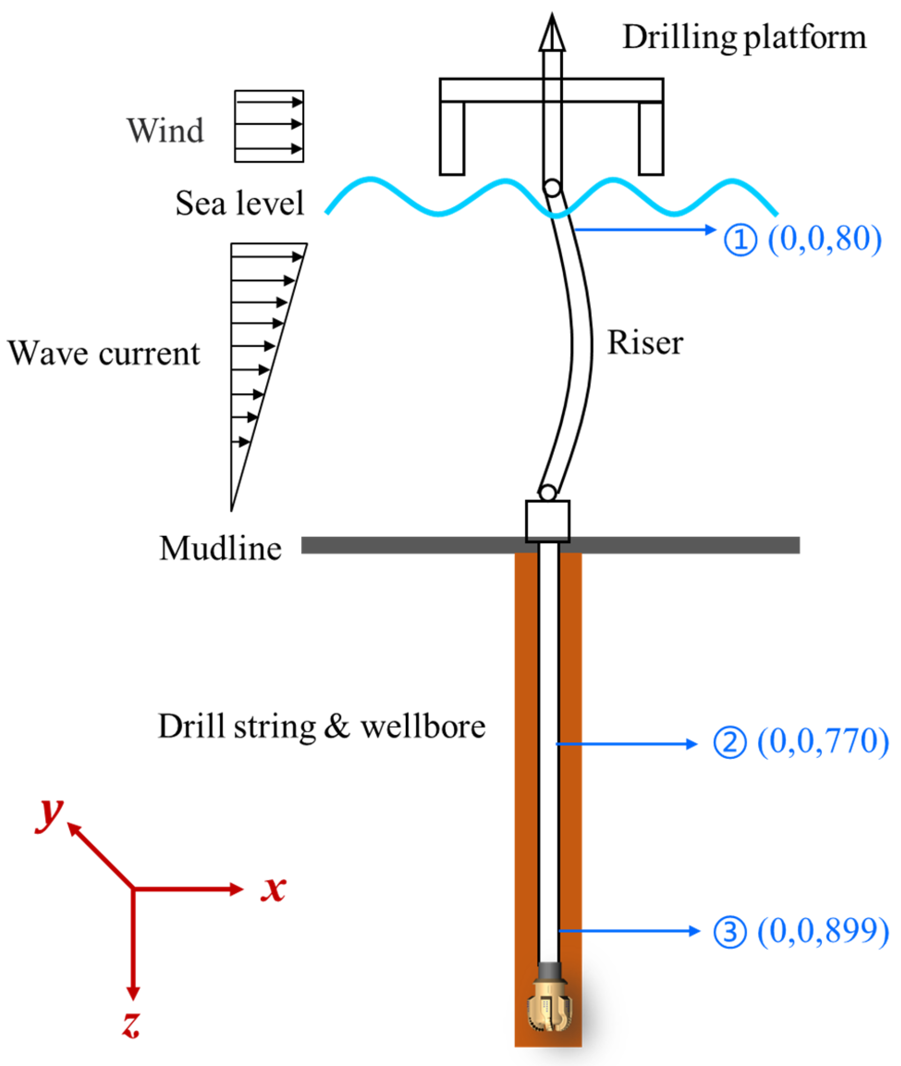
The bending of the riser significantly influences lateral vibration of the drillstring. In this paper, we introduce the riser model in Section 2.1, followed by a specific introduction to both dynamic model of drillstring and its coupling characteristics with the riser model in Section 2.2.

2.1. Riser Model

The dynamic model of deep-water drilling system considers various factors that affect the riser, including rig drift, floating weight, tension force, wind force, wave force, and ocean current force [13,31,32]. To investigate the impact of ocean environmental load on the riser in this model, we analyze the combined effect of wind and wave currents on the riser as follows.
i.
sea wind load
The wind force on the riser is related to the wind speed, and the sea wind load on the object at sea is expressed as the example shown in [33]:
F 1 = K 1 K 2 P A s
P = α v f 2
where F 1 is wind power (N), P is wind pressure (Pa), K 1 , K 2 are, respectively the wind load coefficient and the height variation coefficient of the wind pressure, taken as 0.5 and 1, respectively; A s is the stressed area of the object (m2), α is wind pressure coefficient (0.613 N∙s2/m4), v f is the wind speed (m/s).
ii.
Wave and Current Loads
The total wave force F 2 applied to the offshore structure and the current force f t per unit length of the riser are given by Morison’s equation [34], which are expressed as Equations (3) and (4).
F 2 = 0.5 ρ D C D u u + 0.25 ρ π D 2 C M u ˙
f t = 0.5 d C d ρ v 2
where, ρ is seawater density (kg/m3), D is the projected area of unit cylinder height perpendicular to the wave propagation direction (m2), C D , C M are drag force coefficient and inertia force coefficient, respectively, u , u ˙ and v are, respectively the horizontal velocity, acceleration of water quality point (m/s, m/s2) and current velocity (m/s), and d is the diameter of riser (m), C d is the drag coefficient.
The riser will experience bending and deformation to a certain extent due to ocean environmental loads [35]. To investigate the impact of riser changes on the lateral movement and vibration of the drillstring, we simplified the wind wave current force into wind current load and wind wave current load based on the stress exerted on the riser under ocean environmental loads. We analyzed how these loads affect the riser under varying ocean environmental conditions, and the riser is also affected by gravity and the upper tension force (in this paper, the upper tension and gravity are roughly equal). Assuming that the ocean environmental conditions of a certain water area are: surface wind speed of 1 m/s, tidal range of 1 m, wave height of 0.8 m, wavelength of 3 m, wave period of 3 s, and surface current velocity of 1.5 m/s. The force acting on the riser is a dynamic periodic load, and after simplification, it can be represented by Formula (5) as an excitation load applied to combined force F .
F = A sin ω t
where, A is wind current and wind wave current load calculated by Equations (1)–(4), ω = 2 π / T , and T is wave period.

2.2. Drill String Model

The drillstring system, comprising the drillstring and BHA, etc., is a crucial component of the deep-water drilling system dynamics model. To acquire stress, displacement, and velocity information at various positions along the drillstring system and analyze the impact of the riser on its motion trajectory and vibration characteristics, we have developed a dynamic model for studying its dynamic characteristics. These include impacts between the drillstring system and both the dynamic riser and wellbore, as well as torsion and buckling phenomena within the drillstring. Considering that risers are subject to ocean environmental loads causing continuous movement akin to a dynamic wellbore, impacts between the drilling string system and both wellbore and riser during drilling become complex nonlinear events. In order to gain clearer insights into these intricate nonlinear impacts, our model incorporates frictional impact forces as well as contact forces between the drillstring system with both riser and wellbore surfaces. Figure 2 illustrates this contact section of the drillstring system with respect to both riser and wellbore, when the drillstring is taken as the research object, the black curves with arrows in the figure represent the rotation direction of the drill string system, the direction of the normal force and friction force subjected to the drill string is shown in the figure, where the normal force is perpendicular to the tangential direction and the friction force is parallel to the tangential direction. Where F n is the normal force, F f , F z are the tangential and axial friction resistance, M O is the friction moment, which are calculated by Equations (6)–(8) [36].
F n = μ r d 0 d i 2 k h v r c f ,     μ r > d 0 d i 2 0 ,     0 μ r d 0 d i 2
F f = μ v s F n
M O = d 0 2 μ v s F n
where, μ r is radial displacement of the center of mass of the drillstring, d 0 , d i the outer diameters of the wellbore and the drillstring, respectively, k h is wellbore stiffness, v r is radial velocity of drillstring center of mass, c f is damping factor, v s is stick–slip speed, μ v s is the Coefficient of Friction.
In addition to investigating the impact between the drillstring system and the wellbore and riser, this paper also focuses on analyzing the impact of riser movement on the drillstring system. Due to the significant length-diameter ratio of the drillstring system, a finite element method is employed to discretize both the drillstring and BHA components into multiple units for a more comprehensive analysis of their dynamic characteristics. The joint displacement and stress of each unit in the drillstring are illustrated in Figure 3. In this Figure, u is the longitudinal displacement, v , w are the deflections, θ is the rotation angle. The node displacement and force vector d e , F e , and the displacement f of the drillstring element are calculated as Equations (9)–(11).
d e = u i , v i , w i , θ i x , θ i y , θ i z , u j , v j , w j , θ j x , θ j y , θ j z T
F e = F i x , F i y , F i z , M i x , M i y , M i z , F j x , F j y , F j z , M j x , M j y , M j z T
f = u , v , w , θ T
According to the virtual work principle [37], calculating the virtual work equation and balance equation of the drillstring unit is as shown in Equations (12)–(14):
δ ε T σ d v = δ f T P V d v + δ f T P A d A + δ d e T P e
F e = K e d e
K e = K 0 e + K N e + K σ e
where, K e is the stiffness matrix of drillstring element, K 0 e , K N e and K σ e are linear, large displacement and geometric stiffness matrix, respectively.
The dynamic equations of the drillstring system are nonlinear differential-algebraic equations. Using the Lagrange equation [38,39], the kinematic and dynamic equations of the drillstring element are obtained as Equations (15)–(17), respectively. In the model in this paper, we reduce the order of the second-order differential equation to the first-order differential equation, and use Newton-Rapson [40,41] to solve it.
d d t T U d e ˙ T U d e + R d e ˙ = 0
M d t ¨ + C t d t ˙ + K t d t = F t + R G t
K t = K 0 + K N t + K σ t + K G t
where, T is the kinetic energy of the drillstring element, U is the potential energy of the element, R is the energy dissipation function, M , K and   C are the mass, stiffness and damping matrices of the element, respectively, R G is the resistance vector of the dynamic clearance element, K 0 , K N , K σ and K G are the stiffness matrices of the linear, large displacement, geometric and dynamic clearance elements, respectively.
Finally, based on the previous research conducted by the research group on the dynamic model of the drillstring [36], we integrated the dynamic riser model and established a comprehensive deep-water drilling system dynamic model. The model disregarded the drift of the drilling platform and the impact of drilling fluid on both riser and drillstring systems, while considering periodic ocean environmental loads acting on the riser. Furthermore, we investigated how riser movement affects the drillstring. In the drillstring model, factors such as impact between the drill string system and the well bore and riser, friction force, penetration depth, bit rock interaction and so on are considered. Among them, the contact force parameters of the drill string system with the riser and well bore and the simplification of the drill string system’s drill assembly are the same as those in reference [36]. It is important to note that in this paper, both riser and drillstring are treated as flexible entities to facilitate a more accurate analysis of their deformation characteristics. Additionally, for better representation of actual offshore drilling scenarios, we simplified the connection between riser and drilling platform into a universal connection with three translational degrees of freedom and one rotational degree of freedom. The dimensional parameters, constraint relations, and boundary conditions of our dynamic model can be found in Table 1 and Table 2.

3. Simulation Analysis

In order to investigate the dynamic response of the deep-water drilling system model under different drilling parameters, three sampling points (1), (2), and (3) are strategically positioned along the drillstring. Specifically, point (1) is situated on the upper section of the riser, point (2) is located in the middle of the drillstring below the mud line, and point (3) is positioned near the drill bit. The precise coordinates for these sampling points can be found in Figure 1. By capturing displacement, acceleration, velocity, rotational speed, impact force data at each sampling point within the drillstring system, Section 3.1 and Section 3.2, respectively, analyze how variations in WOB and rotational speed impact motion and vibration characteristics.

3.1. Influence of WOB

In this section, we conducted simulations and analyses of the dynamic responses of the drillstring at various positions while maintaining a constant deep-water drilling system dynamic model with a rotation speed of 60 rpm and varying WOB values of 12 t, 16 t, 20 t, and 30 t. We then analyzed the motion state of the drillstring based on displacement information from three sampling points. The resulting motion trajectories and animations for points (1), (2), and (3) under different WOB conditions are presented in Figure 4 and Figure 5.
It is worth noting that for the purpose of comparing and analyzing the movement trajectory of the drillstring (1) under different conditions, the initial static state inner diameter of the riser is utilized as a reference for sizing the circle in the displacement diagram of drillstring (1). In practical drilling operations, it is typically observed that the displacement at the middle section of the drillstring below the mud line is most significant. However, Figure 4 demonstrates that despite experiencing noticeable changes in displacement at its middle section (2) below the mud line, even greater displacements occur at the top portion of the drill column within riser compared to those below the mud line. This finding diverges from previous research conducted by Ken Qin et al. [29]. The reason behind this discrepancy lies in our study’s simulation of dynamic and periodic variations in riser behavior due to wave and current forces. Consequently, ocean environmental factors exert a strong influence on motion trajectories experienced by drillstring inside risers, resulting in substantial displacements. At the same time, displacing the top (1) point reveals that the drillstring inside the riser exhibits an approximately elliptical motion trajectory under varying bit pressure conditions. The animation of drillstring movement in Figure 5a,c demonstrates significant forward and back whirling at WOB of 12 t and 20 t, respectively, with a relatively regular whirling trajectory. Specifically, at 12 t, forward whirling occurs from 2.7 s to 3.1 s, followed by back whirling from 4.9 s to 5.2 s. At 20 t, the drillstring experiences forward whirling from 4.8 s until reaching a steady state around the mark of 30 s. Moreover, as depicted in (b) and (d) of Figure 4 and Figure 5, respectively, the motion trajectory of the drillstring at weights of 16 t and 30 t appears disorganized with random whirling and strong torsion present. In order to comprehensively investigate how WOB influences whirling formation and torsional vibration in the drillstring system, we focused on analyzing impact force, velocity, acceleration, and rotational speed between position (3), nearby bit location within BHA system, and riser/wellbore. The temporal change curves are shown in Figure 6 and Figure 7. The dynamic model of deep-water drilling system was analyzed through combining impact force with vibration characteristics.
The impact frequency and impact force between the drillstring and BHA wellbore are significantly high under different bit pressure conditions, as illustrated in Figure 6. Although the impact frequency between the drillstring and riser is relatively low, it results in a substantial impact force. This indicates that the dynamic riser will strongly impact the flexed drillstring, thereby influencing its motion state. Furthermore, based on displacement Figure 4 and Figure 5 at various positions of the drillstring, it can be inferred that a higher impact force between the drillstring system and both riser and wellbore leads to more intricate random whirling of the drillstring. The velocity and acceleration of the BHA in Figure 7 reveals distinctive motion characteristics of the drill string under the conditions of 60 rpm and a 20 t WOB. When considering the drill string’s motion trajectory, it can be inferred that despite exhibiting whirling motion, this particular parameter combination results in fewer impact with both the riser and wellbore, leading to reduced impact forces. Additionally, the bottom speed remains more stable compared to other bit weight conditions. Consequently, the overall drilling process of the deep-water drilling system dynamics model is relatively stable under these parameters, allowing for smoother drilling operations. Except for a WOB condition of 20 t mentioned above, similar trends in fluctuation amplitude can be observed in velocity and acceleration under other WOB conditions. Additionally, Figure 7c illustrates significant fluctuations in the rotational speed at the bottom of the drillstring system under different WOB conditions, including instances where the rotational speed reaches zero. Consequently, this leads to stick-slip motion of the drillstring. Hence, it can be inferred that both whirling and stick-slip vibrations occur during the simulation.

3.2. Effect of Speed

In this section, we focus on investigating the impact of rotational speed on the dynamics model of the deep-water drilling system. Under a constant riser force, simulation analysis is conducted with a fixed WOB of 8 t and varying rotational speeds of 40, 60, 80, and 100 rpm, respectively. The motion animation of the drillstring is presented in Figure 8 and Figure 9 by plotting the trajectory of drillstring points (1), (2), and (3).
As shown in Figure 8, the displacement of point (1) in the drilling string system exhibits a significant variation similar to that of different drilling rods and its motion trajectory also takes on an approximate elliptical shape. Unlike WOB, rotational speed exerts a more pronounced influence on the displacement, with higher rotational speeds resulting in larger elliptical eccentricity and flatter displacements. The motion trajectory of the drillstring inside the riser is greatly influenced by its movement under ocean environmental loads. Additionally, slight variations can be observed in the motion trajectories at different positions within the drillstring system. While the whirling trajectory of the drillstring inside the riser tends to be more elliptical, it becomes more circular below mud line. The animation of Figure 8, in conjunction with Figure 9, reveals that at a constant WOB of 60 rpm, the drillstring exhibits a well-defined whirling state, while chaotic motion trajectories are observed at 40, 80, and 100 rpm. Specifically, at 40 rpm, the drillstring initially displays a back whirling and then transitions into a complex random whirling; at 80 rpm, it also starts with a back whirling and subsequently transforms into a forward whirling; whereas at 100 rpm, the drillstring exhibits the most intricate maximum displacement motion trajectory. Notably, taking the example of the drillstring animation from time point 22.9 s to 23.2 s in Figure 9d, rapid changes between forward and back whirling occur within just intervals of 0.3 s duration. This phenomenon persists throughout the simulation process from time point 4.2 s to 30 s accompanied by high-frequency random whirling patterns. The complexity of the drillstring’s motion pattern increases as drilling speed rises when examining different speeds’ influence on its motion trajectories. In order to further analyze how rotational speed affects the dynamics model of deep-water drilling systems, the impact force between the drilling system and riser/wellbore, velocity, acceleration, and rotational speed data at the bottom of the drillstring were also plotted (as shown in Figure 10 and Figure 11).
The impact force between the drilling string system, riser, and wellbore exhibits similar magnitude and frequency to the analysis results in Section 3.1, as depicted in Figure 10, except for stable drilling at 60 rpm. Unlike WOB, the impact force also increases with rotational speed, particularly during impacts between BHA and wellbore wall. At 100 rpm, it is 39.3% larger than at 80 rpm and 83.5% larger than at 40 rpm. This analysis result aligns with the relationship between impact force and rotational speed described by Equation (6). As shown in Figure 11, the amplitude, frequency, and speed fluctuation of BHA’s velocity and acceleration are higher at 100 rpm compared to those at both 80 rpm and 40 rpm. Similar to the Section 3.1 findings, stick-slip vibration occurs within the drilling string under different rotational speeds as well. Considering BHA’s rotational speed fluctuations under various WOB further suggests that apart from whirling vibration, varying degrees of stick-slip vibration and whirling will manifest within the deep-water drilling system dynamics model.

4. Discussion and Conclusions

Figure 7 illustrates the comparison of BHA vibration response under different WOB conditions, indicating that an increase in WOB does not significantly affect the peak value and fluctuation degree of lateral velocity, acceleration, and rotational speed. This suggests that WOB has a weak impact on the velocity, acceleration, and rotational speed at the bottom of the drillstring, which is consistent with previous research on land drilling [22,26]. However, high rotational speeds can result in complex motion patterns and elevated levels of vibration due to frequent changes between forward and back whirling as well as impacts with the wellbore and riser. In order to further analyze the impact of drilling parameters on the bottomhole speed, we conducted an analysis of the speed profile at point (3) within the drillstring system using a combination of parameters 3.1 and 3.2. Subsequently, we constructed a box plot illustrating variations in bottomhole speed under different conditions, as depicted in Figure 12. The box diagram provides a more precise depiction of speed fluctuations. By comparing the box patterns in Figure 12a,b, it is evident that an increase in the input speed parameter leads to a greater fluctuation trend of speed near the bit, compared to WOB. To further validate this conclusion and explore the impact force between BHA and wellbore under various parameters, we conducted a total of 30 sets of simulation analyses with different combinations of bit pressure (4, 8, 12, 16, 20, and 24 t) and rotational speeds (40, 60, 80, 100, and 120 rpm). The impact of both WOB and rotational speed on the drillstring was analyzed by examining changes in impact force between BHA and wellbore under different parameters (Figure 13). As depicted in Figure 13, the relationship between WOB and impact force is not prominent. When the WOB increases to 24 t, the impact force becomes negligible; however, an increasing trend can be observed when there is an increase in rotational speed, especially when the WOB ranges from 100 to 120 rpm except for 20 and 24 t. The analysis regarding the influence of both WOB and rotational speed on impact force aligns with findings from Section 3.1 and Section 3.2 on drillstring motion trajectory, thus confirming our previous inference.
Furthermore, based on the aforementioned motion characteristics of the drillstring under varying WOB and rotational speeds, it can be observed that there exists an optimal combination of WOB and rotational speed for smooth drilling in deep-water drilling systems within a constant load in the ocean environment and drill assembly. By analyzing the impact force curve between BHA and wellbore under different parameters, it is noted that a point with minimal impact force occurs at the inflection point of the curve, indicating a specific combination of WOB and speed with low impact force. As previously discussed, greater impact forces lead to increased complexity in random whirling within the drillstring. When considering Figure 12 alongside this observation, it can be concluded that elevated rotational speeds may result in significant whirling occurring within the BHA section of deep-water drilling system dynamics models. Therefore, appropriately increasing WOB while selecting suitable rotational speeds ensures safe and stable drilling operations in deep-water drilling engineering projects where no excessive bending occurs in the drillstring. In this paper, a riser model is established to analyze the influence of WOB and speed on drillstring motion trajectory and vibration characteristics under periodic dynamic load disturbance. The dynamic model of the deep-water drilling system couples with the drillstring dynamic model. By utilizing displacement, velocity, acceleration, rotational speed, and impact force information at different positions of the drillstring under various drilling parameters, we have derived the following conclusions.
  • The motion trajectory of the drillstring in the dynamic model of deep-water drilling system is significantly affected by the motion of the riser. Inside the riser, the whirling trajectory of the drillstring resembles an ellipse which becomes flattened when maintaining a constant WOB.
  • Under determined ocean environment and riser parameters, there exists a combination of WOB rotational speed parameters that result in small impact forces as well as minimal fluctuation range for speed, acceleration, and velocity ensuring relatively stable drilling operations.
  • Compared to speed variations, WOB has a relatively minor impact on drillstring movement. Higher speeds lead to increased impact forces between the drillstring system and both riser and wellbore surfaces increasing chances for random whirling occurrences. The WOB can be appropriately increased during actual construction, provided that the drillstring maintains minimal bending, and a suitable speed can be selected to ensure secure and stable drilling operations.

Author Contributions

Writing—original draft preparation, software, W.H.; project administration, Y.H.; methodology, Q.X. All authors have read and agreed to the published version of the manuscript.

Funding

This research was funded by [Natural Science Foundation of China], grant number [42372360], and APC by [China University of Geosciences (Beijing)].

Data Availability Statement

Data is unavailable due to privacy.

Conflicts of Interest

Author Yingming He is employed by the company CNOOC Research Institute Co., Ltd., and declared that the research was conducted in the absence of any commercial or financial relationships that could be construed as a potential conflict of interest.

References

  1. Blevins, R.D.; Coughran, C.S.; Utt, M.E.; Raghavan, K. Drilling-Induced Riser Vibration. In Proceedings of the International Ocean and Polar Engineering Conference, San Francisco, CA, USA, 25−30 June 2017. [Google Scholar]
  2. Jie, H.C.; Tie, Y.; Song, T.Y. The analysis on coupling vibration of drill string and marine riser in deep-water drilling. Int. J. Multiphys. 2013, 7, 53–60. [Google Scholar]
  3. Aguiar, R.; Tocantins, J.P.; Marquinez, V.; Baines, V.; Barreto, D.; Gozzi, D.; França, R. Drilling Optimization Using Model-Based Design and Stratigraphic Zonation: Successful Application in Brazilian Deep Water Pre-Salt Carbonate Reservoir. In Proceedings of the SPE Annual Technical Conference and Exhibition, Moscow, Russia, 22–24 October 2019; p. D012S067R003. [Google Scholar]
  4. Liqiu, P.; Xi, W.; Xiuling, Z.; Chenchao, L.; Rui, Y. The Integrated Drilling Technology to Solve Well Construction Challenges in the Pre-Salt Reservoirs of Ultra-Deep Water. In Offshore Technology Conference Asia; OTC: Hollister, MO, USA, 2018. [Google Scholar]
  5. Pinto, C.; Lima, A. Mechanical specific energy for drilling optimization in deepwater Brazilian salt environments. In Proceedings of the IADC/SPE Asia Pacific Drilling Technology Conference and Exhibition, Singapore, 22–24 August 2016; p. D011S005R003. [Google Scholar]
  6. Israel, R.R.; D’Ambrosio, P.; Leavitt, A.D.; Shaughnessey, J.; Sanclemente, J. Challenges of directional drilling through salt in deepwater Gulf of Mexico. In Proceedings of the SPE/IADC Drilling Conference and Exhibition, Orlando, FL, USA, 5–7 March 2008; p. SPE–112669-MS. [Google Scholar]
  7. Chatar, C.; Israel, R.R.; Cantrell, A.J. Drilling Deep in Deep Water: What It Takes to Drill Past 30,000 ft. In Proceedings of the IADC/SPE Drilling Conference and Exhibition, New Orleans, LA, USA, 2–4 February 2010. [Google Scholar]
  8. Chatar, C.; Mohan, S.; Imler, M.D. Overcoming a difficult salt drilling environment in the Gulf of Mexico: A case study. In Proceedings of the IADC/SPE Drilling Conference and Exhibition, New Orleans, LA, USA, 2–4 February 2010. [Google Scholar]
  9. Tudorache, V.-P.; Avram, L.; Antonescu, N.-N. Aspects on offshore drilling process in deep and very deep waters. Technol. Sci. 2020, 5, 157–172. [Google Scholar]
  10. Major, I.; Big-Alabo, A.; Odi-Owei, S. Effect of drill string rotation on the dynamic response of drilling risers. Int. J. Appl. Mech. Eng. 2015, 20, 503–516. [Google Scholar]
  11. Furnes, G.; Hassanein, T.; Halse, K.; Eriksen, M. A field study of flow induced vibrations on a deepwater drilling riser. In Proceedings of the Offshore Technology Conference, Houston, TX, USA, 4–7 May 1998; p. OTC–8702-MS. [Google Scholar]
  12. Brekke, J.N. Key elements in ultra-deep water drilling riser management. In Proceedings of the SPE/IADC Drilling Conference and Exhibition, Amsterdam, The Netherlands, 27 February–1 March 2001; p. SPE–67812-MS. [Google Scholar]
  13. Mao, L.; Liu, Q.; Zhou, S.; Wang, G.; Fu, Q. Deep water drilling riser mechanical behavior analysis considering actual riser string configuration. J. Nat. Gas Sci. Eng. 2016, 33, 240–254. [Google Scholar]
  14. Mao, L.; Zeng, S.; Liu, Q. Dynamic mechanical behavior analysis of deep water drilling riser under hard hang-off evacuation conditions. Ocean Eng. 2019, 183, 318–331. [Google Scholar]
  15. Liu, J.; Ma, X.; Zhang, X.; Zhang, Z.; Liu, G. Axial vibration of deep-water drilling risers under lifting conditions. J. Pet. Sci. Eng. 2022, 209, 109903. [Google Scholar]
  16. Liu, X.-Q.; Sun, H.-X.; Yu, M.-R.; Qiu, N.; Li, Y.-W.; Liu, F.-L.; Chen, G.-M. Mechanical analysis of deepwater drilling riser system based on multibody system dynamics. Pet. Sci. 2021, 18, 603–617. [Google Scholar]
  17. Yang, J.; Li, L.; Yang, Y.; Zhang, M. Research on stability of deepwater drilling riser system in freestanding mode. Ocean Eng. 2023, 279, 114439. [Google Scholar]
  18. Chang, Y.; Zhang, C.; Wu, X.; Shi, J.; Chen, G.; Ye, J.; Xu, L.; Xue, A. A Bayesian Network model for risk analysis of deepwater drilling riser fracture failure. Ocean Eng. 2019, 181, 1–12. [Google Scholar]
  19. Liao, C.-M.; Balachandran, B.; Karkoub, M.; Abdel-Magid, Y.L. Drill-string dynamics: Reduced-order models and experimental studies. J. Vib. Acoust. 2011, 133, 041008. [Google Scholar]
  20. Liu, Y.; Gao, D. A nonlinear dynamic model for characterizing downhole motions of drill-string in a deviated well. J. Nat. Gas Sci. Eng. 2017, 38, 466–474. [Google Scholar]
  21. Xie, D.; Huang, Z.; Ma, Y.; Vaziri, V.; Kapitaniak, M.; Wiercigroch, M. Nonlinear dynamics of lump mass model of drill-string in horizontal well. Int. J. Mech. Sci. 2020, 174, 105450. [Google Scholar]
  22. Huang, W.; Gao, D. Combined effects of wellbore curvature, connector, and friction force on tubular buckling behaviors. SPE J. 2019, 24, 2083–2096. [Google Scholar]
  23. Hu, Y.; Di, Q.; Zhu, W.; Chen, Z.; Wang, W. Dynamic characteristics analysis of drillstring in the ultra-deep well with spatial curved beam finite element. J. Pet. Sci. Eng. 2012, 82, 166–173. [Google Scholar]
  24. Xue, Q.; Leung, H.; Huang, L.; Zhang, R.; Liu, B.; Wang, J.; Li, L. Modeling of torsional oscillation of drillstring dynamics. Nonlinear Dyn. 2019, 96, 267–283. [Google Scholar]
  25. Cai, M.; Mao, L.; Xing, X.; Zhang, H.; Li, J. Analysis on the nonlinear lateral vibration of drillstring in curved wells with beam finite element. Commun. Nonlinear Sci. Numer. Simul. 2022, 104, 106065. [Google Scholar]
  26. Cheng, J.; Sun, Y.; Yu, Y.; Chen, L.; Wu, J. Numerical analysis of drill string whirl for vertical well based on rolling model and small-strain shell element. J. Pet. Sci. Eng. 2022, 214, 110565. [Google Scholar]
  27. Li, W.; Huang, G.; Ni, H.; Yu, F.; Huang, B.; Jiang, W. Experimental study and mechanism analysis of the motion states of bottom hole assembly during rotary drilling. J. Pet. Sci. Eng. 2020, 195, 107859. [Google Scholar]
  28. Liu, Q.; Zhou, S.; Jiang, W.; Liu, J.; Yang, X.; Wang, G. A dynamic model of marine risers/pipes under the drilling operation condition and sea environment. Nat. Gas Ind. 2013, 33, 6–12. [Google Scholar]
  29. Qin, K.; Di, Q.; Zhou, X.; He, Y.; Wang, W.; Chen, F.; Zhang, H. Nonlinear dynamic characteristics of the drill-string for deep-water and ultra-deep water drilling. J. Pet. Sci. Eng. 2022, 209, 109905. [Google Scholar]
  30. Pessier, R.C.; Wallace, S.N.; Oueslati, H. Drilling Performance is a Function of Power at the Bit and Drilling Efficiency. J. Pet. Technol. 2012, 64, SPE-151389-MS. [Google Scholar]
  31. Chakrabarti, S.K.; Frampton, R.E. Review of riser analysis techniques. Appl. Ocean Res. 1982, 4, 73–90. [Google Scholar]
  32. Tan, Q.; Yuan, J.L.; Deng, J.G. Study on the variations of corner and load on bottom ball joint of deep-water drilling riser. Appl. Mech. Mater. 2013, 318, 547–550. [Google Scholar]
  33. Fang, G.J. Static analysis of deep-water marine riser subjected to both axial and lateral forces in its installation. J. Nat. Gas Sci. Eng. 2014, 19, 84–90. [Google Scholar]
  34. Wolfram, J. On alternative approaches to linearization and Morison’s equation for wave forces. Proc. R. Soc. Lond. Ser. A Math. Phys. Eng. Sci. 1999, 455, 2957–2974. [Google Scholar]
  35. Zhu, W.; Zhang, Y.; Zhang, H.; Di, Q. Mechanical behavior of a drilling riser with buoyant blocks when it enters into deep water. Ocean Eng. 2020, 216, 107820. [Google Scholar]
  36. Shan, Y.; Xue, Q.; Wang, J.; Li, Y.; Wang, C. Analysis of the influence of downhole drill string vibration on wellbore stability. Machines 2023, 11, 762. [Google Scholar]
  37. Gooneratne, C.P.; Li, B.; Deffenbaugh, M.; Moellendick, T. Instruments, Measurement Principles and Communication Technologies for Downhole Drilling Environments; Springer: Berlin/Heidelberg, Germany, 2019. [Google Scholar]
  38. Liao, C.-M.; Balachandran, B.; Karkoub, M. Drill-string dynamics: Reduced-order models. In Proceedings of the ASME International Mechanical Engineering Congress and Exposition, Lake Buena Vista, FL, USA, 13–19 November 2009; pp. 451–460. [Google Scholar]
  39. Tucker, W.; Wang, C. An integrated model for drill-string dynamics. J. Sound Vib. 1999, 224, 123–165. [Google Scholar]
  40. Auriol, J.; Kazemi, N.; Innanen, K.; Shor, R.J. Combining formation seismic velocities while drilling and a PDE-ODE observer to improve the drill-string dynamics estimation. In Proceedings of the 2020 American Control Conference (ACC), Denver, CO, USA, 1–3 July 2020; pp. 3120–3125. [Google Scholar]
  41. Barreau, M. Stability Analysis of Coupled Ordinary Differential Systems with a String Equation: Application to a Drilling Mechanism. Ph.D. Thesis, Université Paul Sabatier-Toulouse III, Toulouse, France, 2019. [Google Scholar]
Figure 1. Dynamic Model of Deep-water Drilling System.
Machines 12 00112 g001
Figure 2. Cross section of drillstring system in contact with riser wellbore.
Machines 12 00112 g002
Figure 3. Displacement and Stress of Drill String Beam Element Node.
Machines 12 00112 g003
Figure 4. (ad) are the motion trajectories of points (1), (2) and (3) of the drillstring under the condition that the WOB is, respectively 12 t, 16 t, 20 t and 30 t at the rotating speed of 60 rpm.
Machines 12 00112 g004aMachines 12 00112 g004b
Figure 5. (ad) are the are the simulation animation of drillstring system under the condition that the rotating speed of 60 rpm is 12 t, 16 t, 20 t and 30, respectively.
Machines 12 00112 g005aMachines 12 00112 g005b
Figure 6. (ac) are, respectively the time-varying curves of impact force between riser and drillstring, drillstring and borewellbore, BHA and borewellbore under different WOB conditions at 60 rpm.
Machines 12 00112 g006aMachines 12 00112 g006b
Figure 7. (ac) are the curves of lateral speed, lateral acceleration and rotational speed with time at position (3) under different WOB conditions when the rotational speed is 60 rpm.
Machines 12 00112 g007aMachines 12 00112 g007b
Figure 8. (ad) are the motion trajectories of points (1), (2) and (3) of the drillstring under the condition that the rotating speeds of 8 t WOB are 40 rpm, 60 rpm, 80 rpm and 100 rpm, respectively.
Machines 12 00112 g008aMachines 12 00112 g008b
Figure 9. (ad) are the simulation animation of drillstring under the conditions of WOB 8 t and rotating speed of 40 rpm, 60 rpm, 80 rpm and 100 rpm, respectively.
Machines 12 00112 g009aMachines 12 00112 g009b
Figure 10. (ac), respectively show the time variation curves of impact forces between riser and drillstring, drillstring and wellbore, and BHA and wellbore under different rotational speeds at WOB 8 t.
Machines 12 00112 g010aMachines 12 00112 g010b
Figure 11. (ac) are the curves of lateral speed, lateral acceleration and rotational speed of position (3) with time under different rotational speeds when the WOB is 8 t.
Machines 12 00112 g011aMachines 12 00112 g011b
Figure 12. (a,b) are the rotating speed change of the drillstring system (3) point under the conditions of rotating speed 60 rpm, WOB 12, 16, 20, 30 t, WOB 8 t, rotating speed 40, 60, 80, 100 rpm.
Machines 12 00112 g012
Figure 13. Impact force of BHA with wellbore for different drilling parameters.
Machines 12 00112 g013
Table 1. Model Dimensions.
Model ComponentRiserDrill StringDrill Collar
Length/(m)300750150
ID/(mm)48012771.4
OD/(mm)530146203.2
ρ /(kg/m3)785078507850
E /(Gpa)210210210
Poisson ratio0.290.230.23
Table 2. Constraint Relations and Boundary Conditions.
ConstraintFixationUniversalRotation
LocationRiser + Subsea wellhead, Drill string system + Bit, Wellbore + GroundRiser + Offshore drilling platformDrill string
LoadImpact & contact forceWOB & TorqueGravity
ComponentDrill string system and Riser, Bit and Wellbore, Bit and RockDrill stringAll
Disclaimer/Publisher’s Note: The statements, opinions and data contained in all publications are solely those of the individual author(s) and contributor(s) and not of MDPI and/or the editor(s). MDPI and/or the editor(s) disclaim responsibility for any injury to people or property resulting from any ideas, methods, instructions or products referred to in the content.

