An Air Spring Resonant Vibration Exciter for Large Structures

 , , and
Abstract
1. Introduction
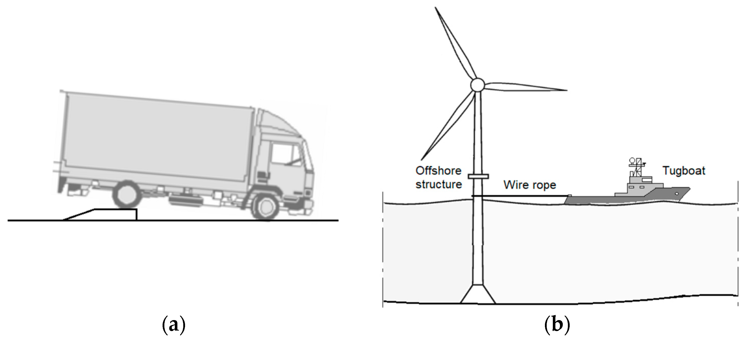
- By inducing a free response of the structure by applying an impulse excitation provided by an impact force or by suddenly releasing a load [12,13]. For example (Figure 1), free vibration may be generated by means of impulsive excitation due to a truck going down a step to excite a bridge or by suddenly releasing the force exerted by a tugboat on an offshore structure. In [14], an interesting loading hammer is presented. It comprises a mass raised by an electric motor to a predetermined height. Upon reaching this height, the mass is disengaged from the electric motor through an electromagnetic clutch and released onto the structure below. A sensor detects the movement of the mass and, promptly after impact, a brake engages to inhibit any rebound off the structure.
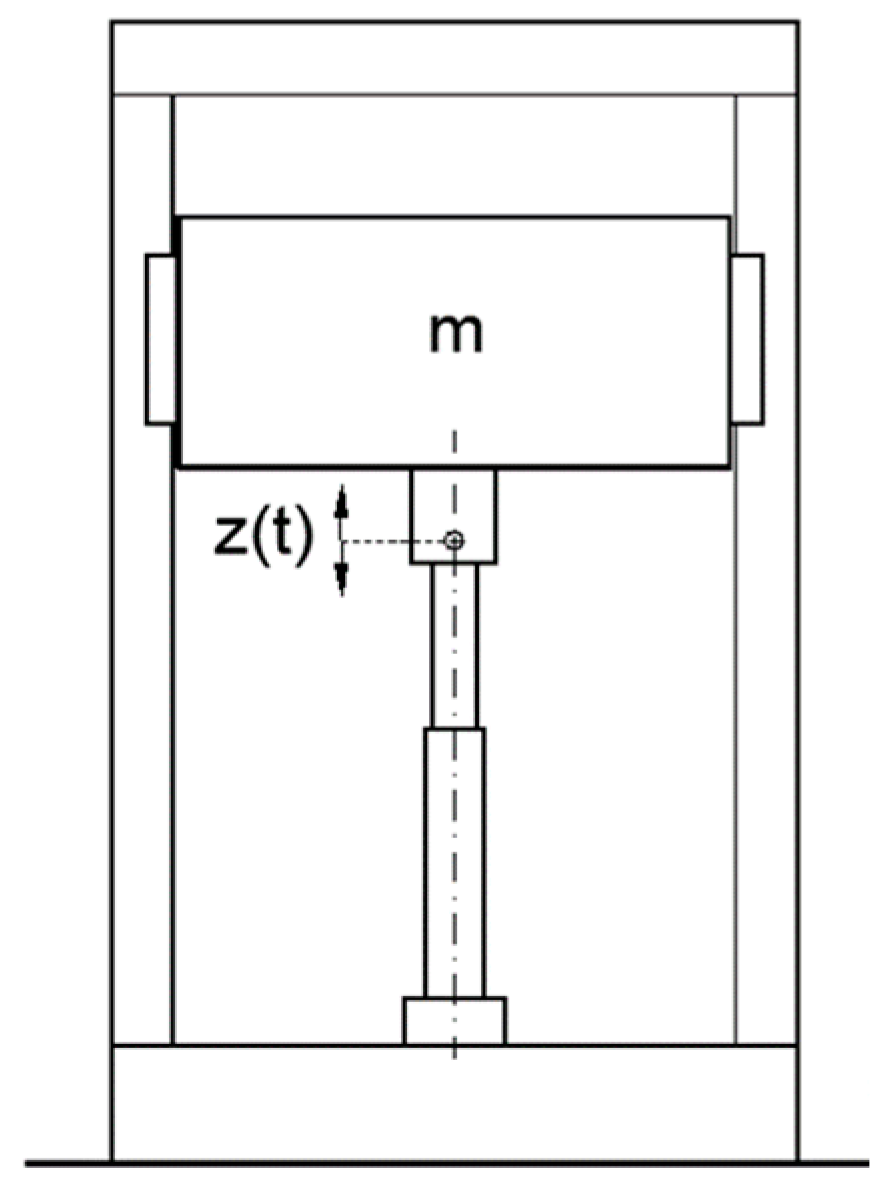
- By adopting a vibration exciter, i.e., a device able to provide a harmonic force, such as actuators, shakers, counter-rotating unbalanced discs, etc. Some vibration exciters need a ground support to which the actuator must be fixed, as in this case represented in Figure 2, where a hydraulic cylinder is adopted to excite a bridge. In this case, the distance between the ground and the bridge is covered by a truss. In some cases, the ground support is not available (as, for example, if the distance between the ground and the bridge is very large) and other type of exciters must be used such as counter-rotating discs supporting eccentric masses to generate a harmonic unidirectional force (Figure 3a). Such devices were widely used in the 1960s to excite structures for seismic tests [15,16]. In the same era, exciters based on reciprocating compressed air engines or internal combustion engines (Figure 3b), as well as some with a mass moved by a hydraulic actuator (Figure 4), were developed. Nowadays, commercial exciters, constituted by a mass that is driven to move in a reciprocating way, are available [17] and able to operate in the low frequency range 0.5–20 Hz; to exert a sufficiently high force, the masses are forced to perform reciprocating motions characterized by long strokes.
- The environmental excitation consists in detecting small vibrations of the structure due to random excitations generated by artificial sources (road or railway traffic, industrial plant, etc.) or by natural sources (wind, seismic microtremor, etc.). In this case, the analysis adopted to identify the structure modal parameters is known as operational modal analysis (OMA) or as ambient modal identification [18,19]. This is a promising technique since it does not require the use of a vibration exciter and the corresponding expenses; for example, if the structure is sufficiently deformable, the wind acting on it could be sufficient to generate a stochastic action, similar to white noise. Such tests could also be carried out under normal operating conditions if the mass of the pay load is small compared to that of the structure and negligibly influences the natural modes of the structure.
2. Vibration Exciters
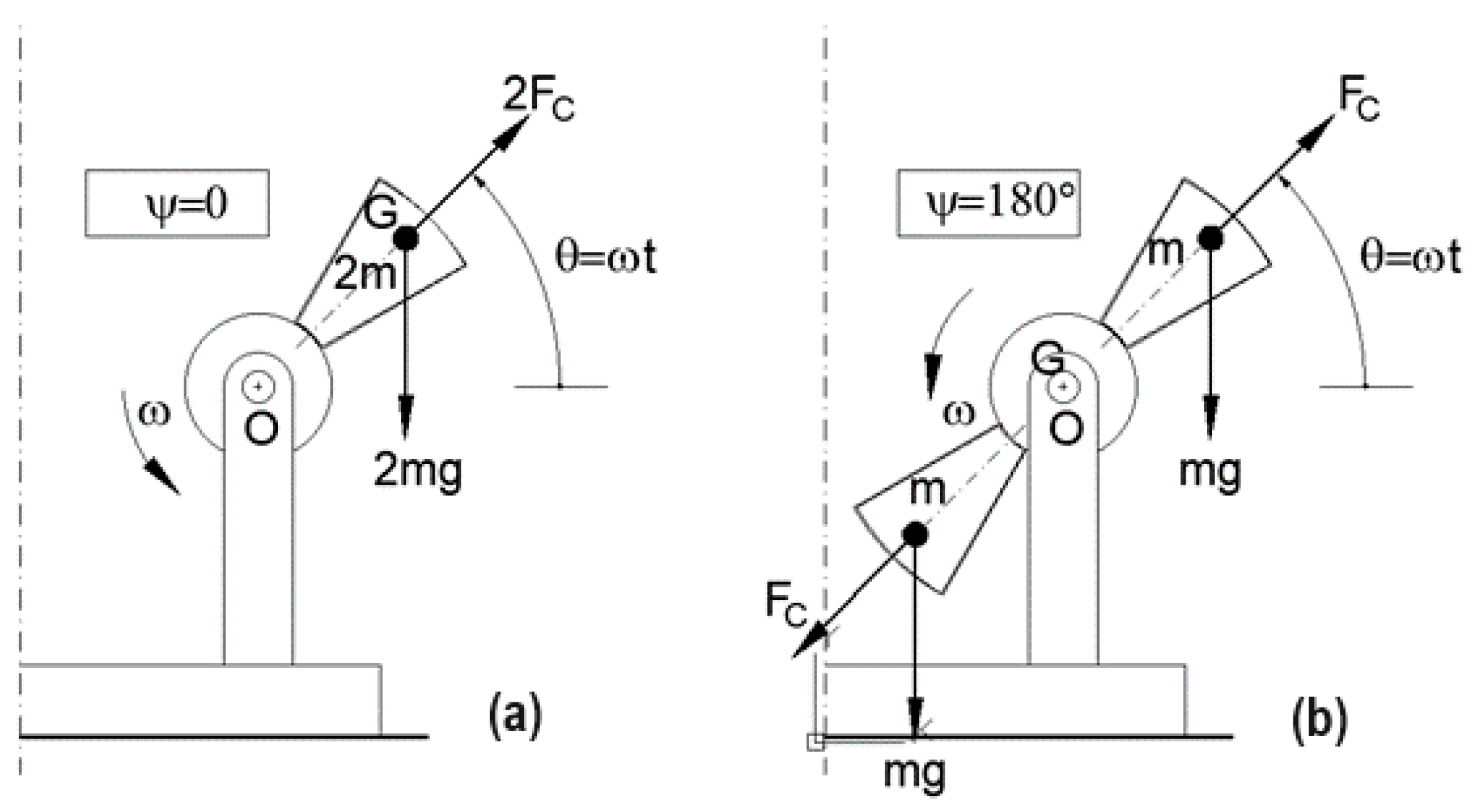
2.1. Counter-Rotating Discs Supporting Eccentric Masses
2.2. Reaction Mass System
3. Vibration Exciter Based on the Use of an Air Spring
4. Air Spring Model
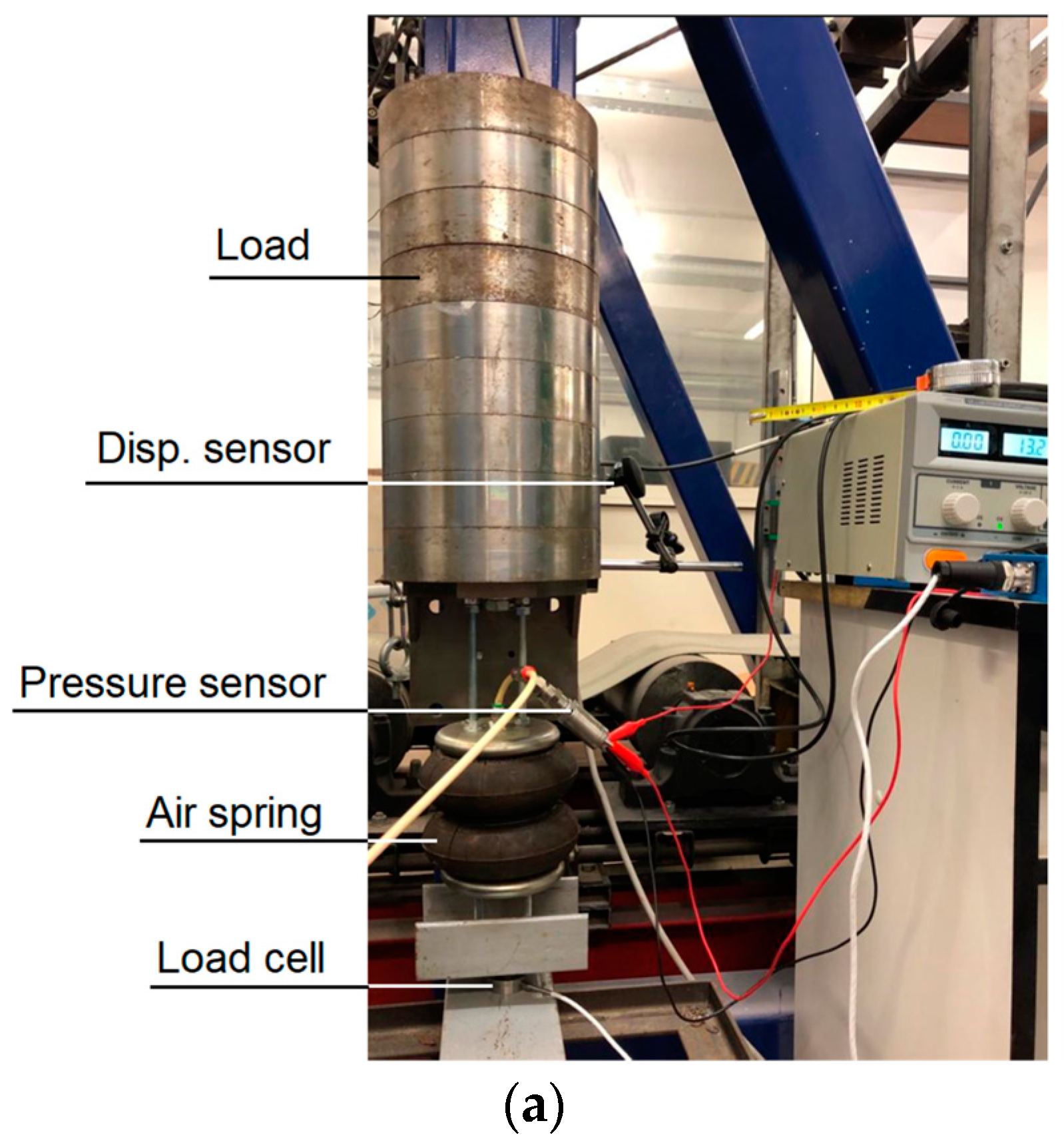
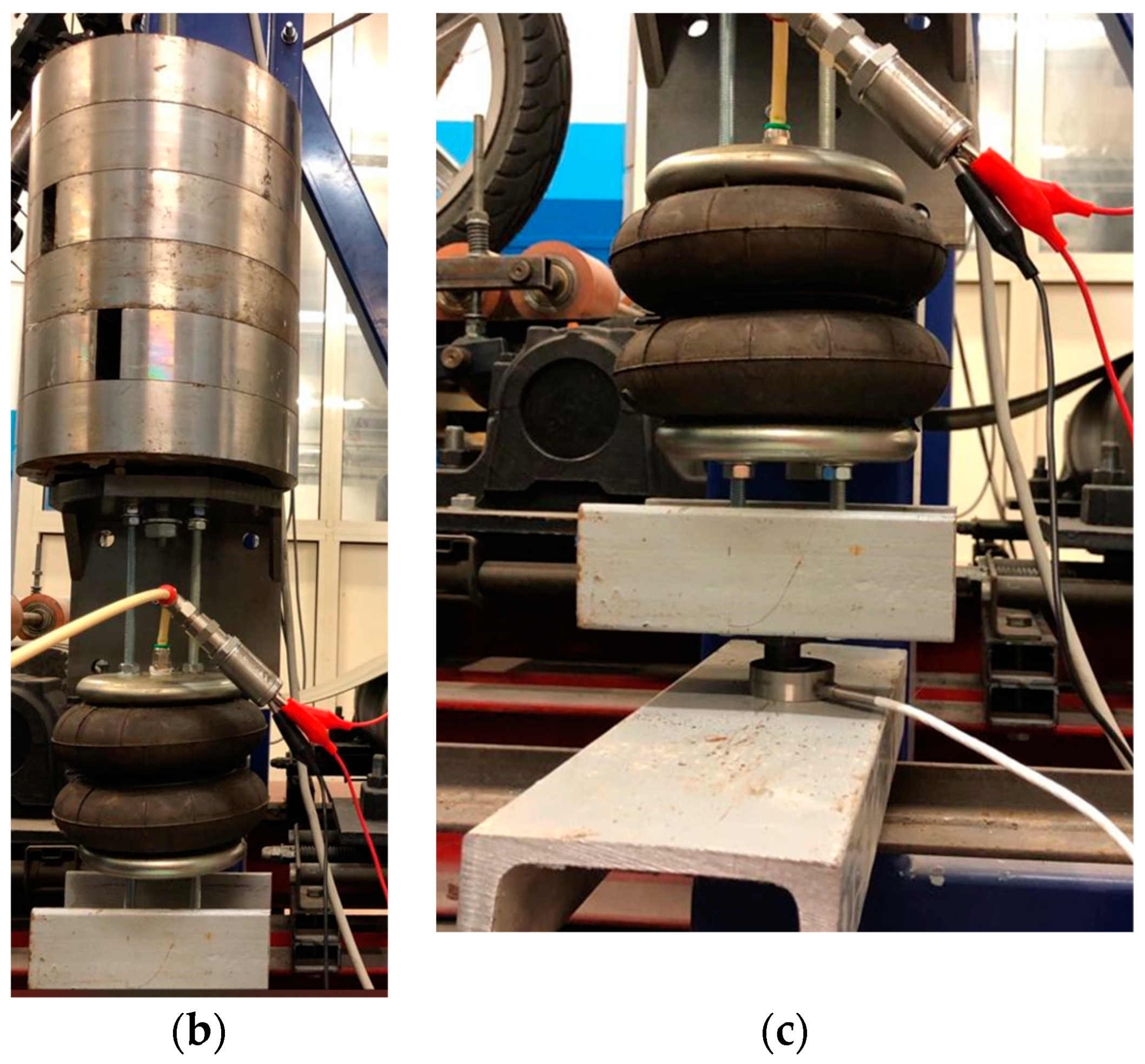
5. Experimental Investigation
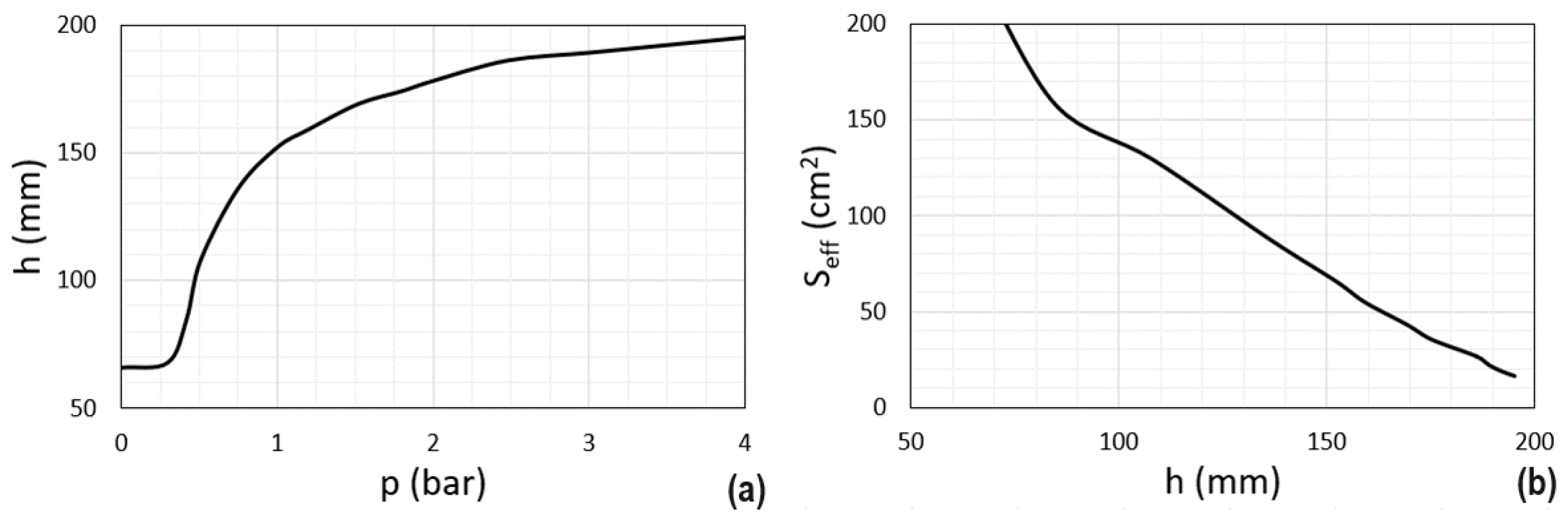
5.1. Static Tests
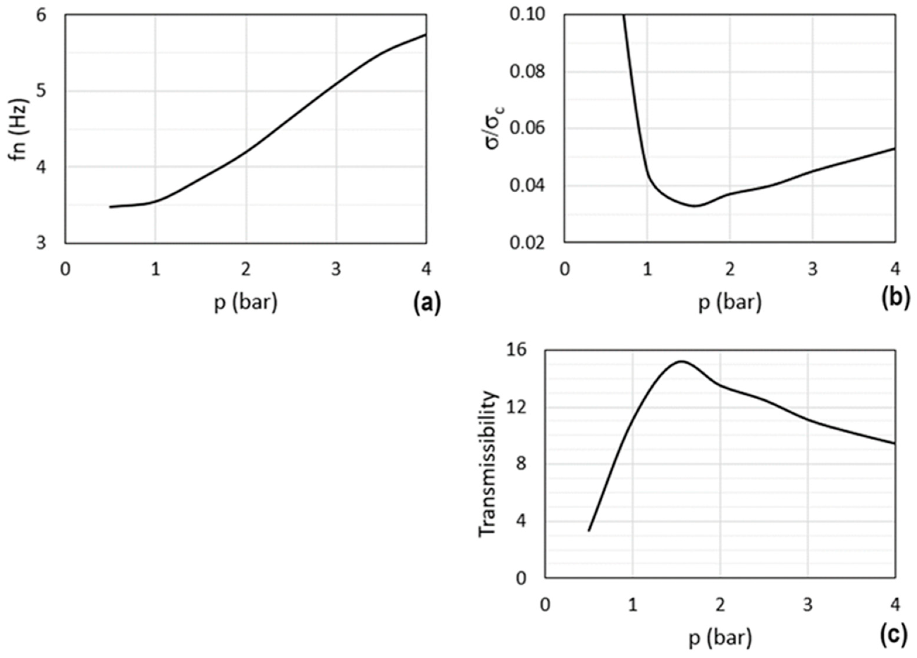
5.2. Dynamic Tests
- -
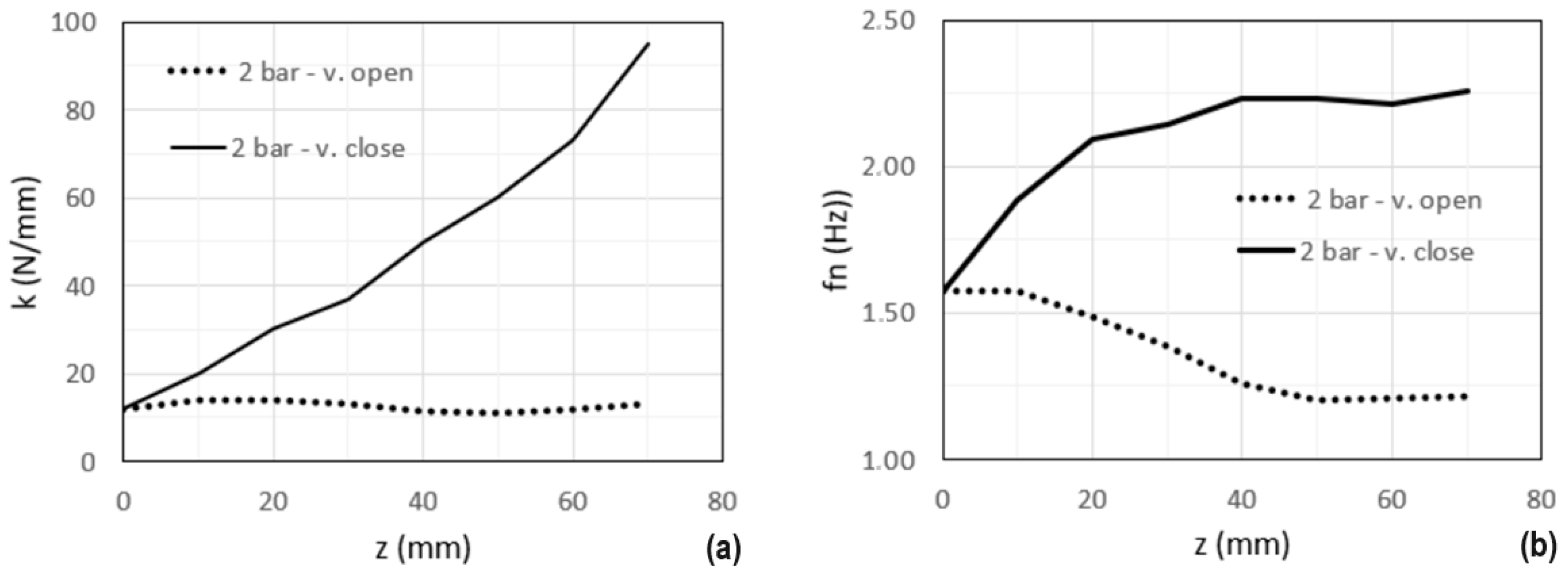
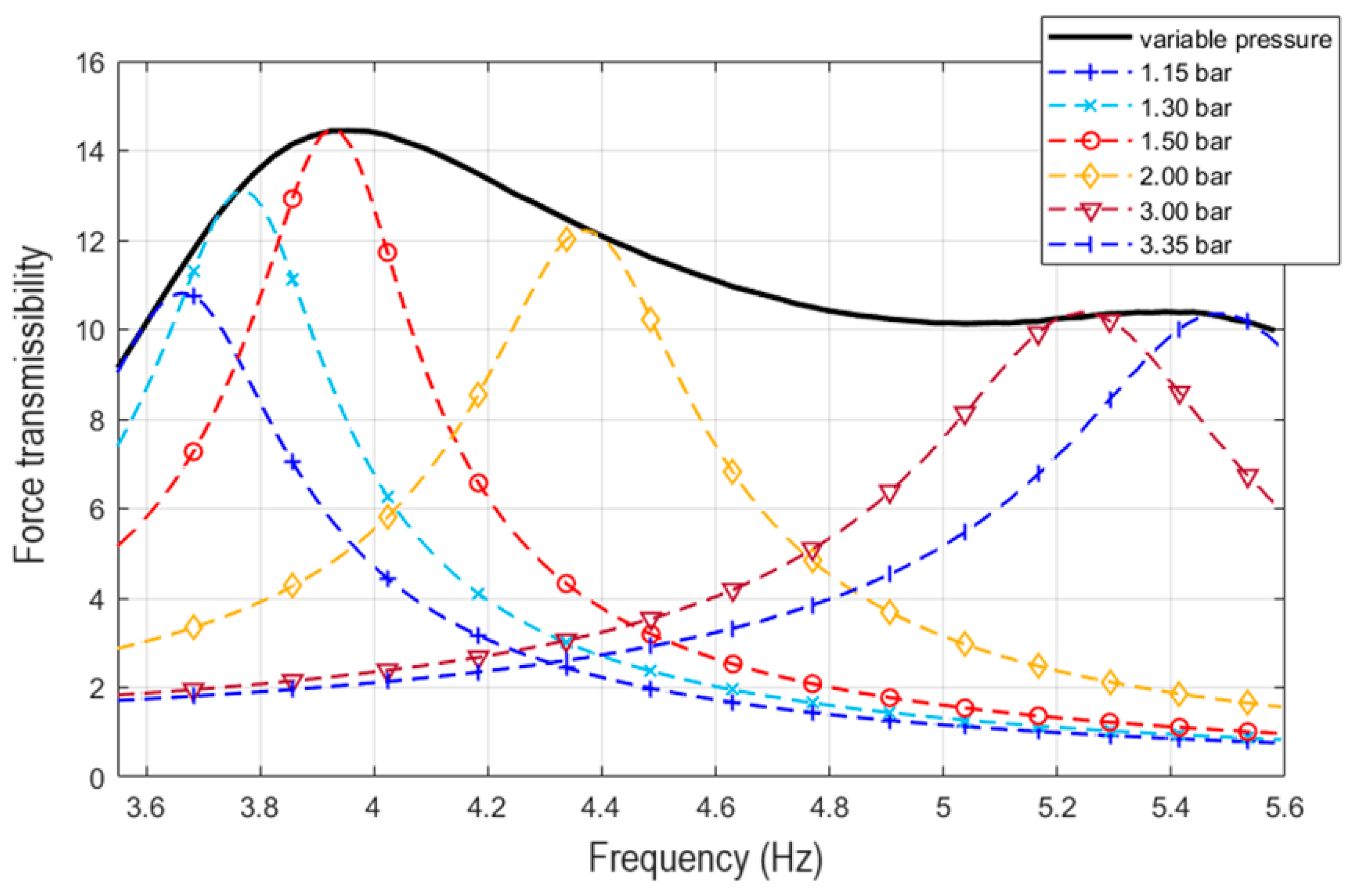
- the natural frequency increases;
- -
- the damping ratio assumes the trend reported in Figure 22b. This trend can be explained by considering that the damping is due to the hysteretic dissipative actions of the elastomeric envelope of the spring and the friction in the guide of the suspended mass. Furthermore, when the spring is highly compressed, the dissipative actions are also due to the friction forces that arise in the contact between the lobes of the spring. For this reason, as the pressure increases, the damping initially decreases rapidly (since the lobes move away from each other) and then it increases slightly;
- -
- the transmissibility is greater than 10 where the damping ratio reaches lower values.
6. Numerical Investigation
7. Conclusions
Author Contributions
Funding
Data Availability Statement
Acknowledgments
Conflicts of Interest
Abbreviations
| e | eccentricity of the centre of mass of the rotating disc |
| f | frequency |
| fn | natural frequency |
| F | vertical component of the inertia force |
| FC | centrifugal force magnitude |
| Fd | driving force magnitude |
| F0 | exciting force magnitude |
| FT | transmitted force |
| g | gravity acceleration |
| h | spring height |
| h0 | initial spring height |
| k | stiffness |
| m | moving mass |
| p | pressure |
| p0 | initial pressure |
| P | load acting on the spring |
| P0 | initial load acting on the spring |
| Pm | driving power |
| r | eccentricity of the centre of mass of each rotating mass |
| S | air spring cross section area |
| Seff | air spring effective area |
| V | volume |
| V0 | initial volume |
| z | moving mass vertical displacement |
| Z | amplitude of the vertical motion of the moving mass |
| γ | exponent of the polytropic transformation |
| θ | angular rotation |
| σ | damping coefficient |
| σcr | critical damping |
| ϕ | phase delay |
| ψ | eccentric masses angular relative position |
| ω | forcing circular frequency |
| ωn | natural circular frequency |
References
- Fujino, Y.; Siringoringo, D.M.; Ikeda, Y.; Nagayama, T.; Mizutani, T. Research and implementations of structural monitoring for bridges and buildings in Japan. Engineering 2019, 5, 1093–1119. [Google Scholar] [CrossRef]
- Bień, J.; Kużawa, M. Dynamic Tests in Bridge Health Monitoring. Stud. Geotech. Mech. 2020, 42, 291–296. [Google Scholar] [CrossRef]
- Sung, Y.; Lin, T.; Chiu, Y.; Chang, K.; Chen, K.; Chang, C. A bridge safety monitoring system for prestressed composite box-girder bridges with corrugated steel webs based on in-situ loading experiments and a long-term monitoring database. Eng. Struct. 2016, 126, 571–585. [Google Scholar] [CrossRef]
- Mishra, M.; Lourenço, P.B.; Ramana, G.V. Structural health monitoring of civil engineering structures by using the internet of things: A review. J. Build. Eng. 2022, 48, 103954. [Google Scholar] [CrossRef]
- Bonopera, M.; Liao, W.; Perceka, W. Experimental–theoretical investigation of the short-term vibration response of uncracked prestressed concrete members under long-age conditions. Structures 2022, 35, 260–273. [Google Scholar] [CrossRef]
- Peeters, B.; Maeck, J.; De Roeck, G. Vibration-based damage detection in civil engineering: Excitation sources and temperature effects. Smart Mater. Struct. 2001, 10, 518–527. [Google Scholar] [CrossRef]
- ASofi, A.; Regita, J.J.; Rane, B.; Lau, H.H. Structural health monitoring using wireless smart sensor network—An overview. Mech. Syst. Signal Process 2022, 163, 108113. [Google Scholar]
- Brancati, R.; Di Massa, G.; Genovese, A. Experimental Investigation to Enhance Performances of MRE in Energy Harvesting. In Mechanisms and Machine Science; Springer: Cham, Switzerland, 2023; Volume 134, pp. 3–10. [Google Scholar]
- Niyirora, R.; Ji, W.; Masengesho, E.; Munyaneza, J.; Niyonyungu, F.; Nyirandayisabye, R. Intelligent damage diagnosis in bridges using vibration-based monitoring approaches and machine learning: A systematic review. Results Eng. 2022, 16, 100761. [Google Scholar] [CrossRef]
- Xin, C.; Wang, C.; Xu, Z.; Wang, J.; Yan, S. Damage detection of structures from motion videos using high-spatial-resolution mode shapes and data fusion. Eng. Fail. Anal. 2022, 140, 106560. [Google Scholar] [CrossRef]
- Dong, C.Z.; Catbas, F.N. A review of computer vision–based structural health monitoring at local and global levels. Struct. Health Monit. 2021, 20, 692–743. [Google Scholar] [CrossRef]
- Mangal, L.; Idichandy, V.G.; Ganapathy, C. Structural monitoring of offshore platforms using impulse and relaxation response. Ocean. Eng. 2001, 28, 689–705. [Google Scholar] [CrossRef]
- Cunha, A.; Caetano, E.; Delgado, R. Dynamic Test on Large Cable Stayed Bridge. J. Bridge Div. Proc. ASCE 2001, 6, 54–62. [Google Scholar] [CrossRef]
- Tian, Y.; Zhang, J.; Xia, Q.; Li, P. Flexibility identification and deflection prediction of a three-span concrete box girder bridge using impacting test data. Eng. Struct. 2017, 146, 158–169. [Google Scholar] [CrossRef]
- Hudson, D.E. A New Vibration Exciter for Dynamic Test of Full-Scale Structures, Earthquake Engineering Research Laboratory, 1961, Pasadena, California. Available online: https://authors.library.caltech.edu/26489/1/Hudson_1961.pdf (accessed on 19 September 2023).
- Jennings, P.C.; Kuroiwa, J.H. Vibration and soil-structure interaction tests nine-story reinforced concrete building. Bull. Seismol. Soc. Am. 1968, 58, 891–916. [Google Scholar] [CrossRef]
- APS Vibration Exciters. Available online: https://www.apsdynamics.com/en/index.html (accessed on 19 September 2023).
- Ghalishooyan, M.; Shooshtari, A. Operational Modal Analysis Techniques and Their Theoretical and Practical Aspects: A Comprehensive Review and Introduction. In Proceedings of the 5th International Operational Modal Analysis Conference (IOMAC 2015), Gijon, Spain, 12–14 May 2015. [Google Scholar]
- Brincker, R.; Zhang, L.; Andersen, P. Modal identification of output-only systems using frequency domain decomposition. Smart Mater. Struct. 2001, 10, 441. [Google Scholar] [CrossRef]
- Maguire, J.R.; Severn, R.T. Assessing the dynamic properties of prototype structures by Hammer Testing. Proc. Inst. Civ. Eng. 1987, 83, 769–784. [Google Scholar] [CrossRef]
- Brancati, R.; De Falco, D.; Di Massa, G.; Pagano, S.; Rocca, E. A Vibration Exciter for Dynamic Testing of Large Structures. In Mechanisms and Machine Science; Springer: Cham, Switzerland, 2023; Volume 134, pp. 217–224. [Google Scholar]
- Lin, Y.; Qian, W.; Li, H.; Ma, H.; Jin, Z. Resonant micro-optic gyroscope equipped with multi-turn waveguide ring resonator. Opt. Commun. 2021, 491, 126954. [Google Scholar] [CrossRef]
- Adiletta, G.; Cascetta, F.; della Valle, S.; Guido, A.R.; Pagano, S.; Vigo, P. A twin rigid straight pipe Coriolis mass flowmeter. Measurement 1993, 11, 289–308. [Google Scholar]
- Di Massa, G.; Pagano, S.; Strano, S. Cabinet and Shelter Vibration Isolation: Numerical and Experimental Investigation. Eng. Lett. 2014, 22, 149–157. [Google Scholar]
- Luczak, M.M.; Peeters, B.; Manzato, S.; Di Lorenzo, E.; Reck-Nielsen, K.; Berring, P.; Haselbach, P.U.; Branner, K. Research sized wind turbine blade modal tests: Comparison of the impact excitation with shaker excitation. J. Phys. Conf. Ser. 2018, 1102, 012022. [Google Scholar] [CrossRef]
- Grimmelsman, K.A.; Fernstrom, E.V.; Carreiro, J.L. Evaluating Economical Dynamic Exciters for Bridge Vibration Testing. Sound Vib. 2014, 39, 11–16. [Google Scholar]
- Lang, G.F.; Snyder, D. Understanding the Physics of Electrodynamic Shaker Performance. Sound Vib. 2001, 35, 24–33. [Google Scholar]
- Chlebo, O.; Sivý, M.; Musil, M.; Čekan, M. Design of the uniaxial shaker with variable stiffness. MATEC Web Conf. 2017, 107, 59. [Google Scholar] [CrossRef]
- Harris, C.M.; Piersol, A.G. Harris’ Shock and Vibration Handbook, 5th ed.; McGraw-Hill: New York, NY, USA, 2002. [Google Scholar]
- Zheng, Y.; Shangguan, W.B.; Rakheja, S. Modeling and performance analysis of convoluted air springs as a function of the number of bellows. Mech. Syst. Signal Process. 2021, 159, 107858. [Google Scholar] [CrossRef]


Disclaimer/Publisher’s Note: The statements, opinions and data contained in all publications are solely those of the individual author(s) and contributor(s) and not of MDPI and/or the editor(s). MDPI and/or the editor(s) disclaim responsibility for any injury to people or property resulting from any ideas, methods, instructions or products referred to in the content. |
© 2024 by the authors. Licensee MDPI, Basel, Switzerland. This article is an open access article distributed under the terms and conditions of the Creative Commons Attribution (CC BY) license (https://creativecommons.org/licenses/by/4.0/).
Share and Cite
Brancati, R.; De Falco, D.; Di Massa, G.; Pagano, S.; Rocca, E. An Air Spring Resonant Vibration Exciter for Large Structures. Machines 2024, 12, 131. https://doi.org/10.3390/machines12020131
Brancati R, De Falco D, Di Massa G, Pagano S, Rocca E. An Air Spring Resonant Vibration Exciter for Large Structures. Machines. 2024; 12(2):131. https://doi.org/10.3390/machines12020131
Chicago/Turabian StyleBrancati, Renato, Domenico De Falco, Giandomenico Di Massa, Stefano Pagano, and Ernesto Rocca. 2024. "An Air Spring Resonant Vibration Exciter for Large Structures" Machines 12, no. 2: 131. https://doi.org/10.3390/machines12020131
APA StyleBrancati, R., De Falco, D., Di Massa, G., Pagano, S., & Rocca, E. (2024). An Air Spring Resonant Vibration Exciter for Large Structures. Machines, 12(2), 131. https://doi.org/10.3390/machines12020131