Article

Synchronization of Dual Induction Motor Multi-Frequency Control Based on Fixed Speed Ratio

School of Mechanical Engineering, Shenyang Ligong University, Shenyang 110159, China
*
Author to whom correspondence should be addressed.
Machines 2024, 12(2), 97; https://doi.org/10.3390/machines12020097
Submission received: 25 December 2023 / Revised: 19 January 2024 / Accepted: 22 January 2024 / Published: 31 January 2024
(This article belongs to the Special Issue Research on Rotor Dynamics and Vibration Control)

Abstract

:
For the same frequency, a vibrating screen usually can only achieve a circular or linear motion trajectory, which will lead to the phenomenon of screen clogging. The compound frequency vibrating screen can achieve various motion trajectories according to different frequency ratios, thus perfectly solving this problem. Thus, the multi-frequency control synchronization problem of the dual induction motor-driven vibration system based on the fixed speed ratio was studied. Firstly, by establishing an electromechanical coupled dynamics model of the vibration system driven by dual induction motors, the response equation of the fixed speed ratio vibration system was derived. Then, the master–slave control strategy was used to control the two induction motors through PID control optimized by a genetic algorithm. The slave motor tracked the main motor through the speed ratio method and achieved fixed speed ratio control synchronization. The simulation analysis showed that the two induction motors vibration system could not achieve self-synchronous motion with a fixed speed ratio, but by using the back propagation proportion-integral-derivative control (BP PID, PID based on BP neural network), we were able to achieve control synchronization with a fixed speed ratio. Herein, the arbitrariness of the fixed speed ratio parameter is also discussed, and controlled synchronous motion of the vibration system with a non-integer fixed speed ratio was realized. Finally, the simulation results were verified through experiments with the fixed speed ratio parameter n = 1.5, which verified the validity of the synchronization theory of fixed speed ratio control in vibrating systems and made it possible to apply it in compound frequency vibrating screens.

1. Introduction

Vibrating machines have a wide range of applications in industry, such as vibrating screens, vibrating feeders, vibrating conveyors, etc. [1,2,3]. This type of vibrating machinery generally depends on a motor with eccentric rotors (ERs) to achieve the screening and transportation of the materials, so a certain relationship is required between the eccentric rotors. The application of vibration synchronization theory in industrial production and the vibration synchronization motion of machines such as vibrating screens and vibrating feeders has been achieved [4,5,6]. And it has also effectively solved the problems existing in engineering. Compound frequency vibrating screens use a variety of excitation frequency vibrations in the screening operation. And this leads to different forces on the material particles on the screen’s surface, so that the screening rate of the material increases and the degree of screen blockage is reduced [7,8,9]. This paper studies the synchronization problem of multi-frequency control of dual induction motors based on a fixed speed ratio and apply it to compound frequency vibrating screens.
The phenomenon of synchronization is widespread in nature and human life, such as in the chirping of summer insects, the marching of military exercises, and the playing of concerts in unison. In the early days, Huygens observed that two pendulums suspended from a beam would swing in opposite directions with the same frequency when they reached a steady state, and then the problem of synchronization attracted widespread attention and research in the scholarly community. Blekman [10] gave the first exact definition of vibration synchronization and applied it to his theoretical study by combining the multiscale method with the vibration model. Wen et al. [11,12] further investigated the vibration synchronization theory of dual induction motors in a vibration system. They performed a highly dynamic coupling characteristic analysis of the whole vibration system, and used the averaging method and Hamilton’s principle to derive the synchronization conditions and stability conditions of the vibration system in a stable synchronization state. Inoue [13] et al. proposed that vibration systems can achieve not only synchronization of same-frequency vibrations, but also synchronization of vibrations with different frequencies when certain conditions are satisfied. Zhao et al. [14] proposed the small parameter averaging method based on the averaging method by introducing the small parameter regression method. Li et al. [15] introduced a mathematical model of an induction motor in a vibrating system with two eccentric rotors, thus establishing an electromechanical coupling model of the vibrating system that investigated the electromechanical coupling mechanism of self-synchronous vibration and vibration synchronous transmission using numerical methods. With the development of vibration synchronization theory, researchers found a commonality, that is, vibration synchronization theory involves synchronization conditions and stability conditions. When the vibration system cannot meet the synchronization conditions or stability conditions, vibration synchronous motion cannot be achieved, so individuals began to introduce control methods into the synchronization. Fang et al. [16,17] studied the self-synchronization of three induction motors in space, making a comparative analysis of the control effects of different influencing factors in vibration synchronization through a cross-coupled control strategy. Based on the self-synchronization of two motors, Kong et al. [18,19,20] used the adaptive sliding mode control algorithm to control the induction motor, which synchronized the control of the two motors and achieved a phase difference of 0 using the improved master–slave control strategy. Huang et al. [21,22] investigated the velocity and phase problems of two eccentric rotors in a vibrating system of two induction motors using the improved master–slave control strategy. They designed a velocity and phase controller using an adaptive sliding film control algorithm, achieving the synchronization of phase and speed control through a cross-coupling strategy. Jin et al. [23] studied the vibration system with two induction motors and proposed a commanded filtered backstepping scheme with full-state constraints, using a control algorithm of neural networks to realize the convergence of the tracking error and synchronization error in the system. Jia et al. [24,25] adopted the control method of fuzzy PID to achieve vibration synchronization of induction motors in the control synchronization and compound synchronous control processes of multiple motors, achieving the zero-phase difference, compound, controlled, and synchronous motion of three and four induction motors with different distributions using the master–slave control strategy.
From the above literature, it can be seen that the synchronization of multi-frequency control in vibrating systems and the application to compound frequency vibrating screens have not been extensively covered. With the former problem, a fixed speed ratio method is firstly represented. Then, the master–slave controlling strategy combined with the BP PID controlling method is proposed. This paper studies the synchronization problem of multi-frequency control of two induction-motor-driven vibration systems based on a fixed speed ratio, and the article is structured as follows. Section 2 combines the kinetic model with the asynchronous motor model to establish the electromechanical coupling model, and gives the response equations for each of the three directions of x , y , and ψ . Section 3 describes the control strategies used and provides a detailed description of the control methods. Section 4 verifies the effectiveness and stability of the proposed method through simulations and experiments. Section 5 summarizes the findings and draws some conclusions.

2. Electromechanical Coupling Model for Vibrating Systems

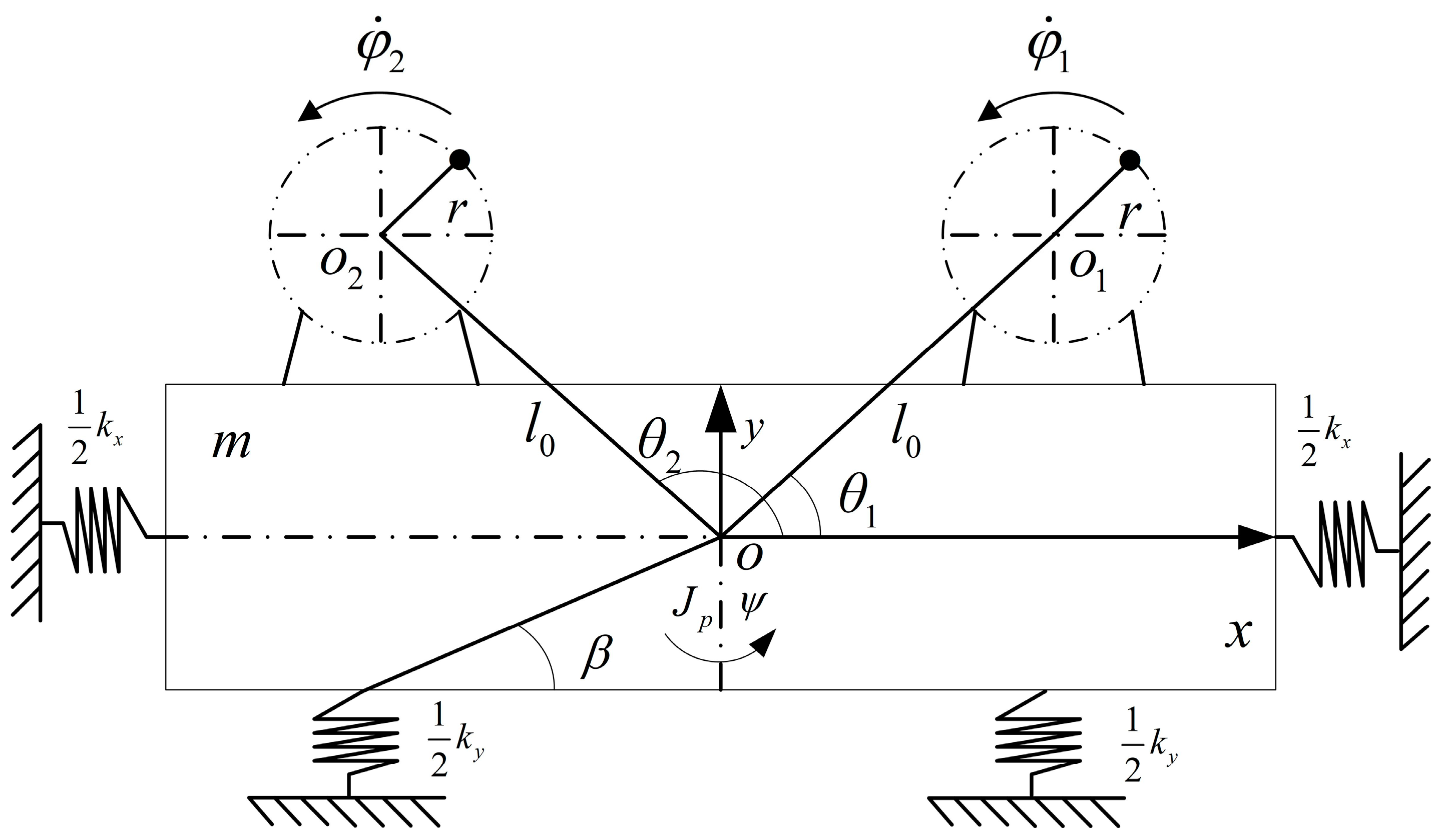
2.1. Dynamic Model of Dual Induction Motor Vibration System

As shown in Figure 1, the vibration system is composed of the following parts from the bottom to top. Firstly, a steel frame base is fixed on the ground. Four linear springs which are symmetrically distributed about the center point o of the body are used at each of the four corners of the steel frame to support the rigid shaking table. The y-axis is the center of the symmetric placement of two induction motors. The right side is motor 1; the left side is motor 2. According to the Lagrange equation, the dynamics equation of multifrequency-controlled synchronization is shown as follows [26].
M x ¨ + f x x ˙ + k x x = i = 1 2 m i r ( φ ˙ i 2 cos φ i + φ ¨ i sin φ i ) M y ¨ + f y y ˙ + k y y = i = 1 2 m i r ( φ ˙ i 2 sin φ i φ ¨ i cos φ i ) J ψ ¨ + f ψ ψ ˙ + k ψ ψ = i = 1 2 m i r l 0 ( φ ˙ i 2 sin ( φ i θ i ) φ ¨ i cos ( φ i θ i ) ) J 1 φ ¨ 1 + f 1 φ ˙ 1 = T e 1 T L 1 J 2 φ ¨ 2 + f 2 φ ˙ 2 = T e 2 T L 2
The symbolic meanings in the formula are listed in Table 1. M = m 1 + m 2 + m . J = M l e 2 J P + ( m 1 + m 2 ) ( l 0 2 + r 2 ) . J 1 m 1 r 2 , J 2 m 2 r 2 , where the load torque is expressed as follows.
T L 1 = m 1 r ( y ¨ cos φ 1 x ¨ sin φ 1 + l 0 ψ ˙ 2 sin ( φ 1 θ 1 ) + l 0 ψ ¨ cos ( φ 1 θ 1 ) ) T L 2 = m 2 r ( y ¨ cos φ 2 x ¨ sin φ 2 + l 0 ψ ˙ 2 sin ( φ 2 θ 2 ) + l 0 ψ ¨ cos ( φ 2 θ 2 ) )

2.2. Model of Asynchronous Motor

A mathematical model of the induction motor in vibration system was established. We selected variable ω i s ϕ r , where i s is divided into i s d and i s q and ϕ r is divided into ϕ r d and ϕ r q . Therefore, the equation of state of the induction motor in the d q two-phase rotating coordinate system can be obtained as follows [27].
L k s d i s d d t = u s d R k s i s d + R r L m L r 2 ϕ r d + ω s L k s i s q L k s d i s q d t = u s q R k s i s q L m L r ϕ r d ω ω s L k s i s d d ϕ r d d t = 1 T r ( L m i s d ϕ r d ) d θ d t = L m i s q T r ϕ r d + ω T e = 3 L m ϕ r d i s q 2 L r
Because this paper uses a squirrel-cage induction motor, the rotor coil inside the induction motor is a short circuit: u r d = u r q . When the system is in a steady state, ϕ r d = constant and ϕ r q = 0 . The symbols’ meanings in the formula are listed in Table 1. T r = L r / R r . L k s = L s L m 2 / L r . R k s = R s + L m 2 R r / L r 2 .

2.3. Controlled Synchronization Response Analysis

According to the literature [22], the model in Figure 1 cannot achieve multi-frequency self-synchronization. Thus, for this part of the impossibility, multi-frequency control synchronization can be achieved by adding a control algorithm to the self-synchronization. Based on the theory of nonlinear dynamics, the speed ratio of the two excitation motors in the fixed-speed-ratio synchronous motion can be expressed as p φ ˙ 1 q φ ˙ 2 = 0 , where p and q are prime numbers of each other. Let φ ˙ 1 = ( p + ε 1 ) ω 0 , φ ˙ 2 = ( q + ε 2 ) ω 0 , φ ¨ 1 = ε ˙ 1 ω 0 , φ ¨ 2 = ε ˙ 2 ω 0 . Then, the speed of the two excitation motors in the vibration system at this time can be expressed as
ω 1 = 0 T 1 φ ˙ 1 ( t ) d t / T 1 ω 2 = 0 T 2 φ ˙ 2 ( t ) d t / T 2
Substituting Equation (4) into (1), we can obtain the response equations of the vibrating system in the three directions: x , y , and ψ .
x = r m r [ cos ( φ 1 + γ x 1 ) μ x 1 + η cos ( φ 2 + γ x 2 ) μ x 2 ] y = r m r [ sin ( φ 1 + γ y 1 ) μ y 1 + η sin ( φ 2 + γ y 2 ) μ y 2 ] ψ = ( r m r l r l e ) [ sin ( φ 1 θ 1 + γ ψ 1 ) μ ψ 1 + η sin ( φ 2 θ 2 + γ ψ 2 ) μ ψ 2 ]
where ω x 2 = k x / M , ω y 2 = k y / M , ω ψ 2 = k ψ / J , r m = m 1 / M , r l = l 0 / l e , η = m 2 / m 1 , ξ x = f x / ( 2 k x M ) , ξ y = f y / ( 2 k y M ) , ξ ψ = f ψ / ( 2 k ψ J ) , μ x i = 1 ω x 2 / ω i 2 ( i = 1 , 2 ) , μ y i = 1 ω y 2 / ω i 2 ( i = 1 , 2 ) , μ ψ i = 1 ω ψ 2 / ω i 2 ( i = 1 , 2 ) , tan γ x i = 2 ξ x ω x / μ x i ω i ( i = 1 , 2 ) , tan γ y i = 2 ξ y ω y / μ y i ω i ( i = 1 , 2 ) , tan γ ψ i = 2 ξ ψ ω ψ / μ ψ i ω i ( i = 1 , 2 ) .
Substituting Equation (5) into (1), we applied the small parameter method. Integrating over the minimum common multiple periods of the two induction motors gave the following.
J 1 ε ¯ ˙ 1 ω 0 + f 1 ω 0 ( p + ε ¯ 1 ) = T ¯ e 1 T ¯ L 1 J 2 ε ¯ ˙ 2 ω 0 + f 2 ω 0 ( q + ε ¯ 2 ) = T ¯ e 2 T ¯ L 2
where the electromagnetic torque T ¯ e 1 = T e 01 k e 01 ε ¯ 1 , T ¯ e 2 = T e 02 k e 02 ε ¯ 2 . The load moment of the vibration system can be written in the following form:
T ¯ L 1 = m 1 r 2 ω 0 ( a 11 ε ¯ ˙ 1 + p b 11 ε ¯ 1 + p 2 κ 1 ) T ¯ L 2 = m 1 r 2 ω 0 ( a 22 ε ¯ ˙ 2 + q b 22 ε ¯ 2 + q 2 κ 2 )
where
a 11 = [ r m cos γ x 1 / μ x 1 + r m cos γ y 1 / μ y 1 + r m r l 2 cos γ ψ 1 / μ ψ 1 ] / 2 b 11 = ω 0 [ r m sin γ x 1 / μ x 1 + r m sin γ y 1 / μ y 1 + r m r l 2 sin γ ψ 1 / μ ψ 1 ] κ 1 = ω 0 [ r m sin γ x 1 / μ x 1 + r m sin γ y 1 / μ y 1 + r m r l 2 sin γ ψ 1 / μ ψ 1 ] / 2 a 22 = η 2 [ r m cos γ x 2 / μ x 2 + r m cos γ y 2 / μ y 2 + r m r l 2 cos γ ψ 2 / μ ψ 2 ] / 2 b 22 = η 2 ω 0 [ r m sin γ x 2 / μ x 2 + r m sin γ y 2 / μ y 2 + r m r l 2 sin γ ψ 2 / μ ψ 2 ] κ 2 = η 2 ω 0 [ r m sin γ x 2 / μ x 2 + r m sin γ y 2 / μ y 2 + r m r l 2 sin γ ψ 2 / μ ψ 2 ] / 2
Bringing the electromagnetic torque and load torque of the induction motor into Equation (6) yields Equation (9).
A ε ¯ ˙ = B ε ¯ + υ
where A = a 11 0 0 a 22 , B = b 11 0 0 b 22 , υ = υ 1 υ 2 T , ε ¯ ˙ = ε ¯ ˙ 1 ε ¯ ˙ 2 T , ε ¯ = ε ¯ 1 ε ¯ 2 T , a 11 = 1 + a 11 , b 11 = ( f 1 / m 1 r 2 + k e 01 / m 1 r 2 ω 0 + p b 11 ) , b 22 = ( f 2 / m 1 r 2 + k e 02 / m 1 r 2 ω 0 + q b 22 ) , a 22 = η + a 22 , υ 1 = T e 01 / m 1 r 2 ω 0 f 1 p / m 1 r 2 p 2 κ 1 , υ 2 = T e 02 / m 1 r 2 ω 0 f 2 q / m 1 r 2 q 2 κ 2 .

2.4. Motion Characteristics Analysis of Vibrating Systems

The response of the vibration system was analyzed in the previous section, and this section describes the characteristic analysis of synchronous motion conducted by changing the motion parameters of the vibration system. By theoretical derivation, the expression of r l can be obtained as follows:
r l = m 1 l 0 2 r m J p + ( 1 + η ) m 1 ( l 0 2 + r 2 )
When the two induction motors are symmetrically distributed about the center of the body, l 0 = 0.5 m remains the same. Due to η = m 2 / m 1 , the purpose of changing the masses of eccentric rotors 1 and 2 can be achieved by changing the parameter of η , thus obtaining the graph of r l as a function of r m . As shown in Figure 2, r m increased when the value of m 1 increased; however, r l monotonically decreased.
Keeping the mass of the eccentric rotor 1 constant and adjusting the distance l 0 from the two induction motors to the center of the body, we obtained the graph of r l as a function of l 0 . After that, we adjusted the parameter η , and the graphs of eccentric rotors 1 and 2 at various masses could be obtained. As shown in Figure 3, the distance from the two induction motors to the center of the body grew farther and farther with the increasing l 0 , and r l increased monotonically.
When the vibration system met the synchronous stability condition, υ = 0 , we substituted it into Formula (9) to obtain:
A ε ¯ ˙ = B ε ¯
If the determinant of matrix A is not zero, and then the matrix A is reversible, so that D = A 1 B . Then, Formula (11) can be expressed as:
ε ¯ ˙ = D ε ¯
According to λ I - D = 0 , the eigenvalue equation is:
λ 2 + d 1 λ + d 2 = 0
where d 1 = D 1 / D 0 , d 2 = D 2 / D 0 , D 0 = a 11 a 22 , D 1 = a 22 b 11 a 11 b 22 , D 2 = b 11 b 22 .
In order to achieve stable synchronous motion, it is necessary to meet the Hurwitz condition so that the synchronous state stability conditions of two eccentric rotors can be obtained as follows:
d 1 > 0 ,   d 2 > 0
The coupling terms of the moment of inertia matrix and stiffness matrix between the eccentric rotors of the two motors were 0, which shows that there was no coupling relationship between the two exciting motors in the vibration system with a fixed speed ratio.

3. Design of the Control System

To achieve arbitrariness of the control system, let p / q = n , with the ratio n as the target variable. A PID control method based on BP neural network (BP PID) was used to realize the synchronization of fixed-speed-ratio control. Therefore, in this section, a master–slave control strategy is first proposed. Based on this, we then describe the BP PID control method.

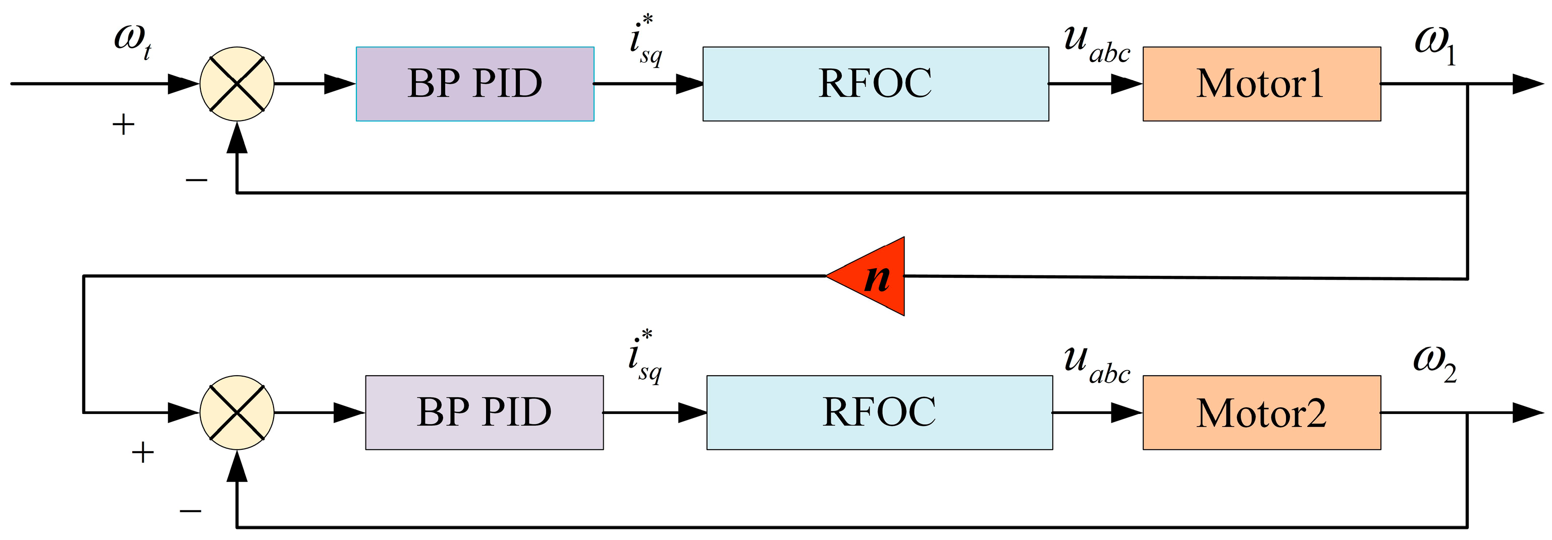
3.1. Design of the Electromechanical Coupling System

As shown in Figure 4, motor 1 is the master motor and motor 2 is the slave motor; motor 2 tracks motor 1 with a fixed speed ratio parameter n. The reason for selecting the master–slave controlling strategy was that a near-resonance phenomenon appeared firstly because of the approximate frequency between the speeds of two motors and the rigid body. This phenomenon resulted in the phase difference being unable to always keep a fixed value when the system was in the stable state. With the proposed master–slave controlling strategy, only if motor 1 worked for the former operation would the phase difference keep the same constant. The rotor flux-oriented control (RFOC) and the controlling method were introduced into the electromagnetic system. ω t represents the target speed, which was input into motor 1 as a given speed. The stator current of the q-axis was then controlled by a modified BP PID control method to control the RFOC. In this way, the output signal of the inverter acted on motor 1, achieving a speed ω 1 for motor 1. ω 1 had two roles: one was to feed back to motor 1 to obtain the speed error for motor speed control adjustment, and the other was used as a speed input and transmitted to motor 2 so that the speed ω 2 of motor 2 could be obtained. Similarly, the control process of motor 2 was the same as that of motor 1, as the speed of motor 2 could be obtained from motor 1. Then, through feedback, it was possible to achieve control of the rotational speed inner ring of motor 2, thus realizing the control synchronization based on the fixed speed ratio.
The RFOC in Figure 4 is shown in Figure 5. Because the control variable which was chosen was current, the RFOC was a current control. With the difference value between the initial speed ω t and the feedback speed ω 1 , the controlling method was adopted to acquire the electromagnetic torque T e , which was used to calculate the stator current i s q on the q-axis. The input on the left in Figure 5 is the current, and i s d on the d-axis can be derived from equation i s d = ϕ r d / L m . ϕ r d is the target value of the initially given magnetic chain; L m is known for a given value. In this way, we obtained U s d and U s q afterwards through PI control. The synchronous magnetic chain angle θ could be derived from the following Equation (15):
θ = ( ω + ω s ) d t
The symbolic meanings in the formula are listed in Table 1, where ω s = L m i s q / ϕ r d T r .

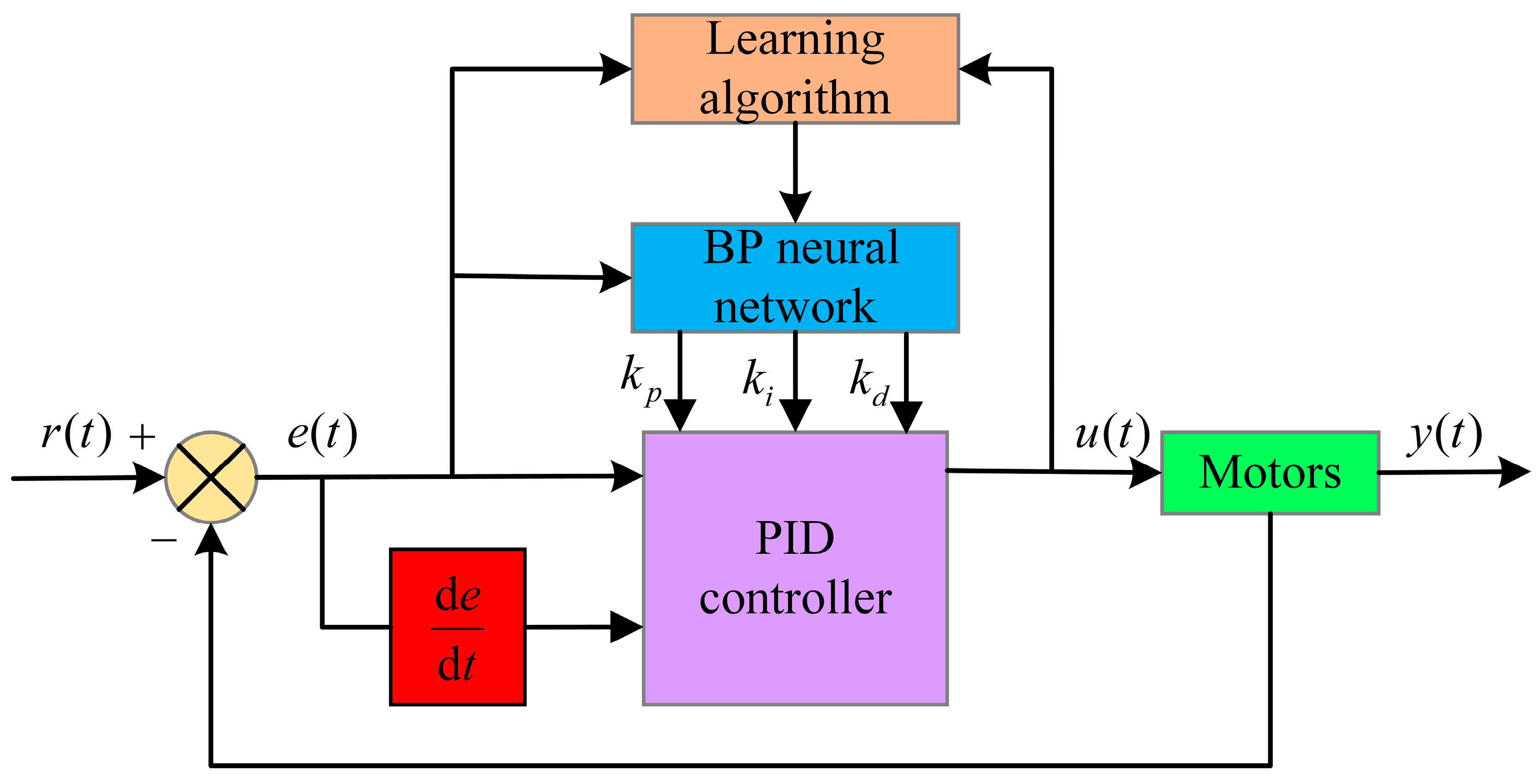
3.2. Design of the BP PID Method

A BP neural network is a multilayer forward neural network that is trained according to the error back propagation algorithm. It can map arbitrarily complex nonlinear relationships, thus making up for the shortcomings of traditional PID controllers in the nonlinear domain. The structural block diagram of the BP neural network PID controller is shown in Figure 6. The BP neural network in this paper was designed as a 3-5-3 structure, where the input layer contained three neurons, the hidden layer contained five neurons, and the output layer contained three neurons. The given, error, and actual values of the system were used as inputs, and the three parameters, k p , k i , and k d , of the PID were used as outputs. The specific structure is shown in Figure 7.
First, we chose the sigmoid type activation function. The hyperbolic tangent function was chosen for the implicit layer, which had the following expressions and derivatives:
f ( x ) = e x e x e x + e x   f ( x ) = 1 f 2 ( x )
The nodes of the output layer were k p , k i , and k d , which are all numbers that cannot be less than 0. Thus, the non-negative hyperbolic tangent function was chosen for the output layer, which had the following expressions and derivatives:
g ( x ) = e x e x + e x   g ( x ) = 2 g ( x ) 1 g ( x )
We sampled the system set value r ( k ) and the actual output value y ( k ) at the k moment, in turn calculating e ( k ) , input layer input, implied layer input, implied layer output, output layer input, and output layer output, in that order.
The inputs into the input layer j were as follows:
o j ( 1 ) = x ( j ) ( j = 1 , 2 , 3 )
The inputs and outputs of the implicit layer i were as follows:
n e t i ( 2 ) = j = 1 3 w i j ( 2 ) o j ( 1 ) o i ( 2 ) ( k ) = f n e t i ( 2 ) ( k ) ( i = 1 , 2 , 3 , 4 , 5 )
The inputs and outputs of the output layer l were as follows:
n e t l ( 3 ) ( k ) = i = 1 5 w l i ( 3 ) o i ( 2 ) ( k ) o l ( 3 ) ( k ) = g n e t l ( 3 ) ( k ) ( l = 1 , 2 , 3 ) k p = o 1 ( 3 ) k i = o 2 ( 3 ) k d = o 3 ( 3 )
Then, by substituting the values of outputs k p , k i , and k d into the formula for incremental digital PID, we calculated the control value u ( k ) of the PID controller output. The increment of control was only related to the system deviation signal at k , k 1 , and k 2 times. The equation for calculation was as follows:
u ( k 1 ) = k p e ( k 1 ) + k i j = 0 k 1 e ( j ) + k d e ( k 1 ) e ( k 2 )
The selected performance indicator function E ( k ) was indicated as follows:
E ( k ) = 1 2 r ( k ) y ( k ) 2
By adjustment of connection weights w l i ( 3 ) in the output layer and connection weights w i j ( 2 ) in the implicit layer, the BP PID control method was improved. To improve the convergence speed of the BP neural network algorithm and obtain better dynamic and static characteristics, the inertia term with ρ as the inertia factor was added. According to the negative gradient rule, when the learning rate is ϑ , the amount of adjustment of the output layer connection weights can be optimized as:
Δ w l i ( 3 ) ( k ) = ϑ E ( k ) w l i ( 3 ) + ρ Δ w l i ( 3 ) k 1
Among which,
E k w l i 3 = E k y k × y ( k ) Δ u ( k ) × Δ u ( k ) o l ( 3 ) k × o l ( 3 ) k n e t l ( 3 ) k × n e t l ( 3 ) ( k ) w l i ( 3 ) k
Furthermore,
y ( k ) Δ u ( k ) = sgn y ( k ) Δ u ( k ) n e t l ( 3 ) ( k ) w l i ( 3 ) k = o i 2 k
Because u ( k ) = u ( k 1 ) + o 1 3 e ( k ) e ( k 1 ) + o 2 3 e ( k ) + o 3 3 e ( k ) 2 e ( k 1 ) + e ( k 2 ) ; therefore,
Δ u ( k ) o 1 ( 3 ) k = e ( k ) e ( k 1 ) Δ u ( k ) o 2 ( 3 ) k = e ( k ) Δ u ( k ) o 3 ( 3 ) k = e ( k ) 2 e ( k 1 ) + e ( k 2 )
Finally, through simplified approximation, we obtained the change amount of the connection weight of the output layer after learning:
Δ w l i ( 3 ) ( k ) = ρ Δ w l i ( 3 ) k 1 + ϑ δ l ( 3 ) o i ( 2 ) k δ i ( 3 ) = e k sgn y k Δ u k Δ u ( k ) o l ( 3 ) ( k ) g n e t l ( 3 ) ( k )
The change amount of connection weights of the implicit layer after learning was:
Δ w i j ( 2 ) ( k ) = ρ Δ w i j ( 2 ) ( k 1 ) + ϑ δ i ( 2 ) o j ( 1 ) ( k ) δ i ( 2 ) = f n e t i ( 2 ) k l = 1 3 δ l ( 3 ) w l i ( 3 ) k

3.3. Step Summary of BP PID Control Algorithm

Through the autonomous learning of a BP neural network, the parameters of the incremental PID controller were adjusted in real time, achieving control of the motors’ speeds and phases. The step summary of the BP PID control algorithm was as follows:
(1)
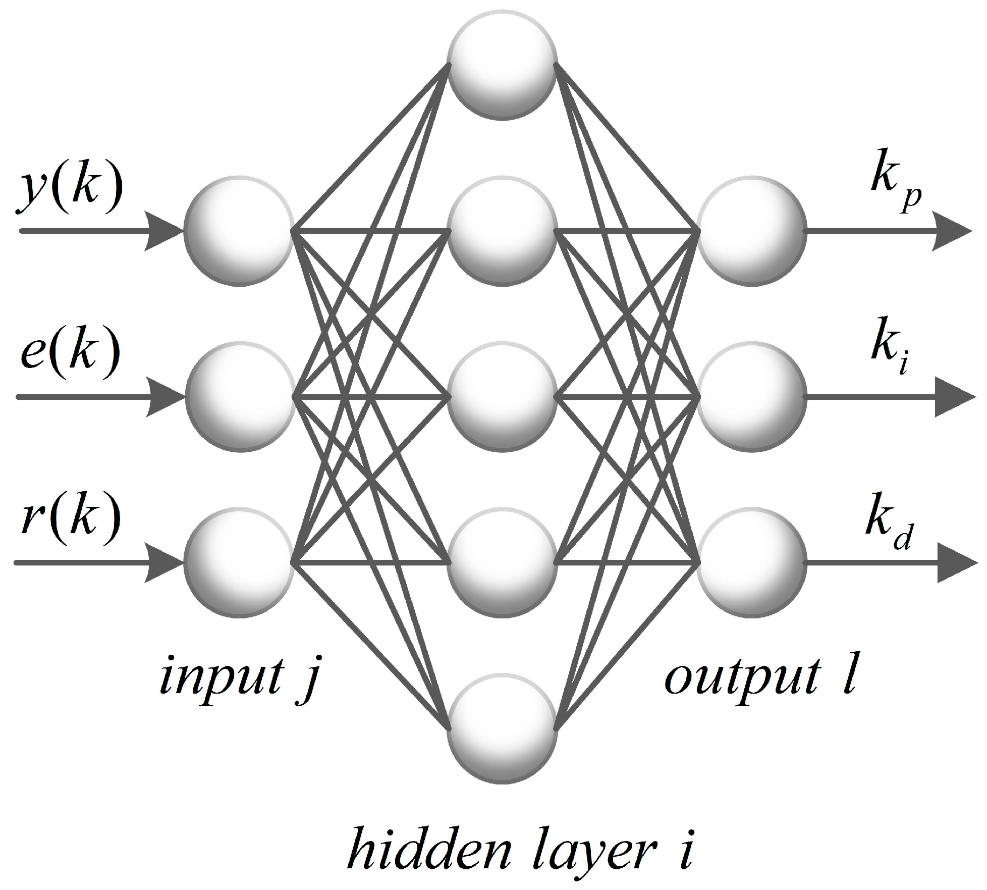
Combined with the control object to determine the structure of the BP neural network, we obtained the number of nodes in input layer and hidden layer. We selected a set of initial random values (0, 0.5) for the connection weight w i j ( 2 ) ( 0 ) of the hidden layer and the connection weight w i j ( 3 ) ( 0 ) of the output layer. The inertia coefficient ρ and the autonomous learning rate ϑ of neural network were determined.
(2)
We sampled the system setting value r k and the actual output value y k at the k time, then calculated e ( k ) = r ( k ) y ( k ) .
(3)
We sampled r ( t ) , y ( t ) , and e ( t )   ( t = k ,   k 1 ,   k 2 ) , respectively, as inputs into the BP neural network.
(4)
According to the Formulas (18)–(20), we calculated the inputs and outputs of each layer of the neural network. Finally, the output values k p , k i , and k d of the BP neural network were obtained.
(5)
According to Formula (21), the output u ( k ) of the incremental PID could be obtained, i.e., the control quantity accepted by the induction motor.
(6)
According to Formula (27), we adjusted the connection weight of the output layer.
(7)
According to Formula (28), we adjusted the connection weights of the implicit layer.
(8)
According to the Formula (22), if the performance index function E ( k ) was less than the set value and the three parameters of the BP neural network satisfied the requirements of the PID controller, we terminated the learning process. On the contrary, if k = k + 1 , we would have returned to step (2) and continued the learning process again.

4. Results and Discussion

In this section, the effectiveness and stability of the method are analyzed by simulation in Matlab/Simulink, using the method of controlling the fixed speed ratio to achieve the multi-frequency synchronous motion of two motors. After performing numerical simulations, it was found that the fundamental frequency self-synchronization could not realize the given fixed speed ratio under the dynamics model. Based on this phenomenon, a numerical simulation of control synchronization based on a fixed speed ratio was carried out for the vibration system by introducing a modified BP neural-network-based PID control method. And the numerical simulation was performed again by changing the fixed speed ratio parameter n . Finally, according to the numerical simulation results, it was proven that the control method of BP PID can achieve controlled synchronous motion with any fixed speed ratio under the dynamics model. The parameters used in the simulation are shown in Table 2 and Table 3. The α indicates the initial phase angle of two motors, and this represents the two motors starting from a resting state. α 0 represents the phase difference angles between two motors.

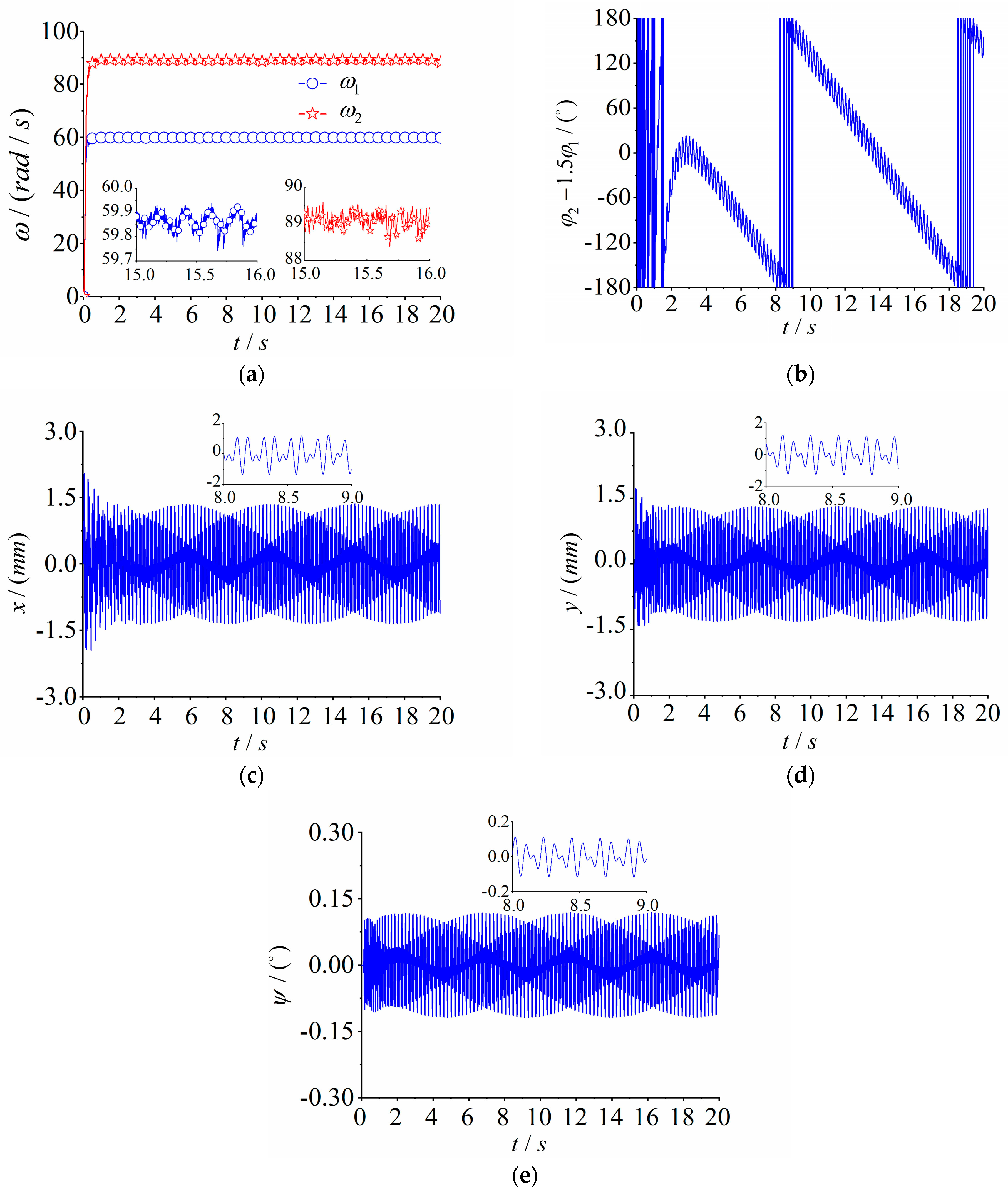
4.1. Numerical Simulation of the Multifrequency Self-Synchronization

Base-frequency self-synchronization can be considered as a special case of self-synchronization at a fixed speed ratio parameter of n = 1 , achieving synchronous motion when the vibration system reaches a steady state, i.e., ω 1 ω 2 = 0 . We can obtain the formula ω 2 / ω 1 = 1 by transforming. Similarly, the same applies to the self-synchronous motion with a fixed speed ratio. When the vibration system reaches the steady state, i.e., n ω 1 ω 2 = 0 , we can obtain the formula ω 2 / ω 1 = n by transforming and by controlling the fixed speed ratio parameter n to achieve multi-frequency self-synchronization motion with two motors. We set the frequency of the two motors to 30 Hz and 45 Hz, respectively. As shown in Figure 8, (a) shows the speeds of the two induction motors of the vibration system. The given speed of the main motor 1 was 60 rad/s. Due to the fixed speed ratio parameter n = 1.5 , the speed of motor 2 stabilized at 90 rad/s. (b) represents the phase difference between the two eccentric rotors. From (b), we know that the phase difference between the two vibration motors was not equal to a constant, and it is obvious that the phase of motor 2 lagged behind the phase of 1.5 times motor 1. As shown in Figure 8c–e, the motor moved in cycles, so the amplitudes appeared to superimpose and cancel periodically. Finally, response curves in the form of the x , y , and ψ directions appeared, revealing that the wave peak and trough values of the response curves showed non-sinusoidal trends. To sum up, it is known that the vibration system driven by two induction motors cannot achieve self-synchronous motion with a fixed speed ratio.

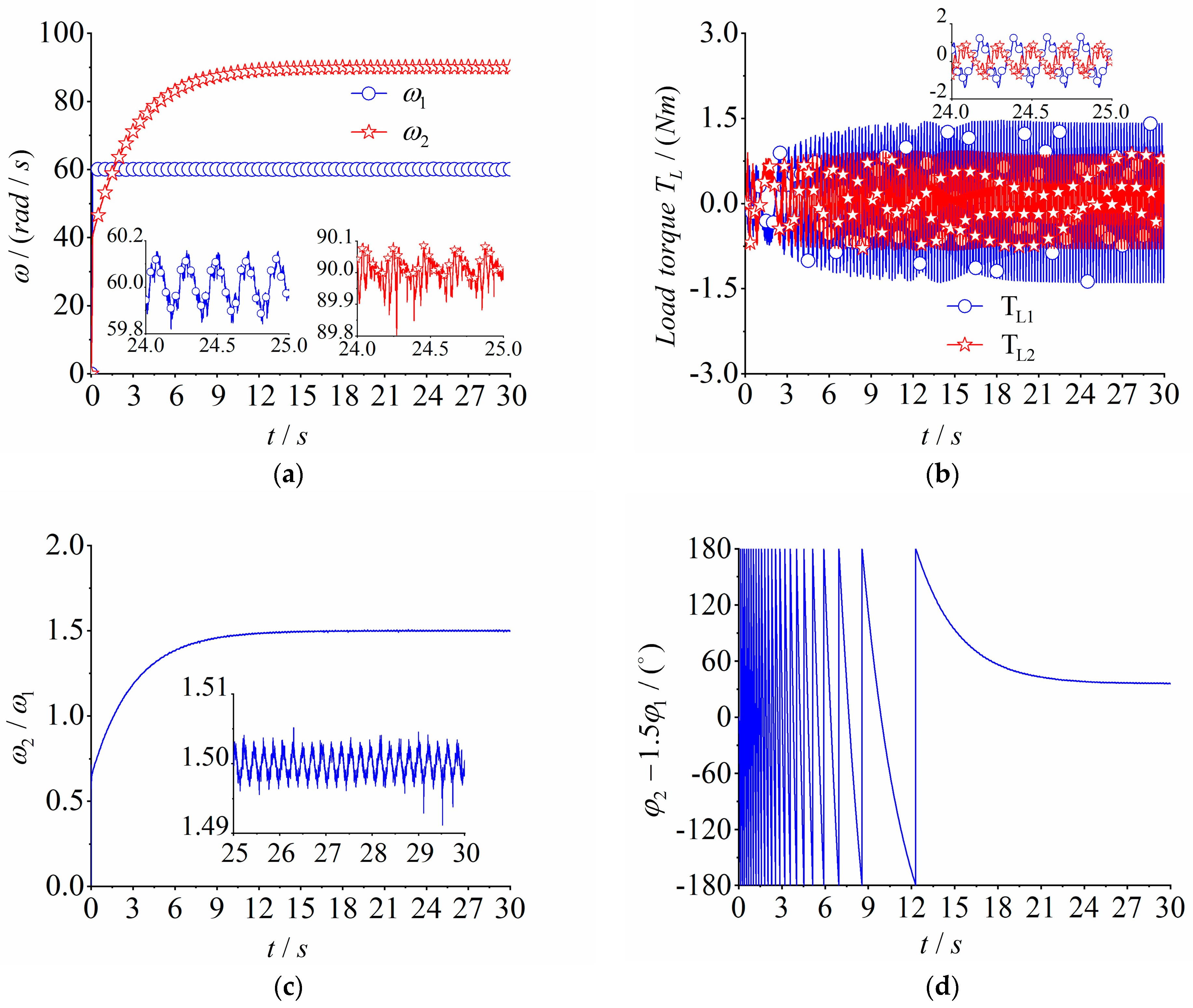
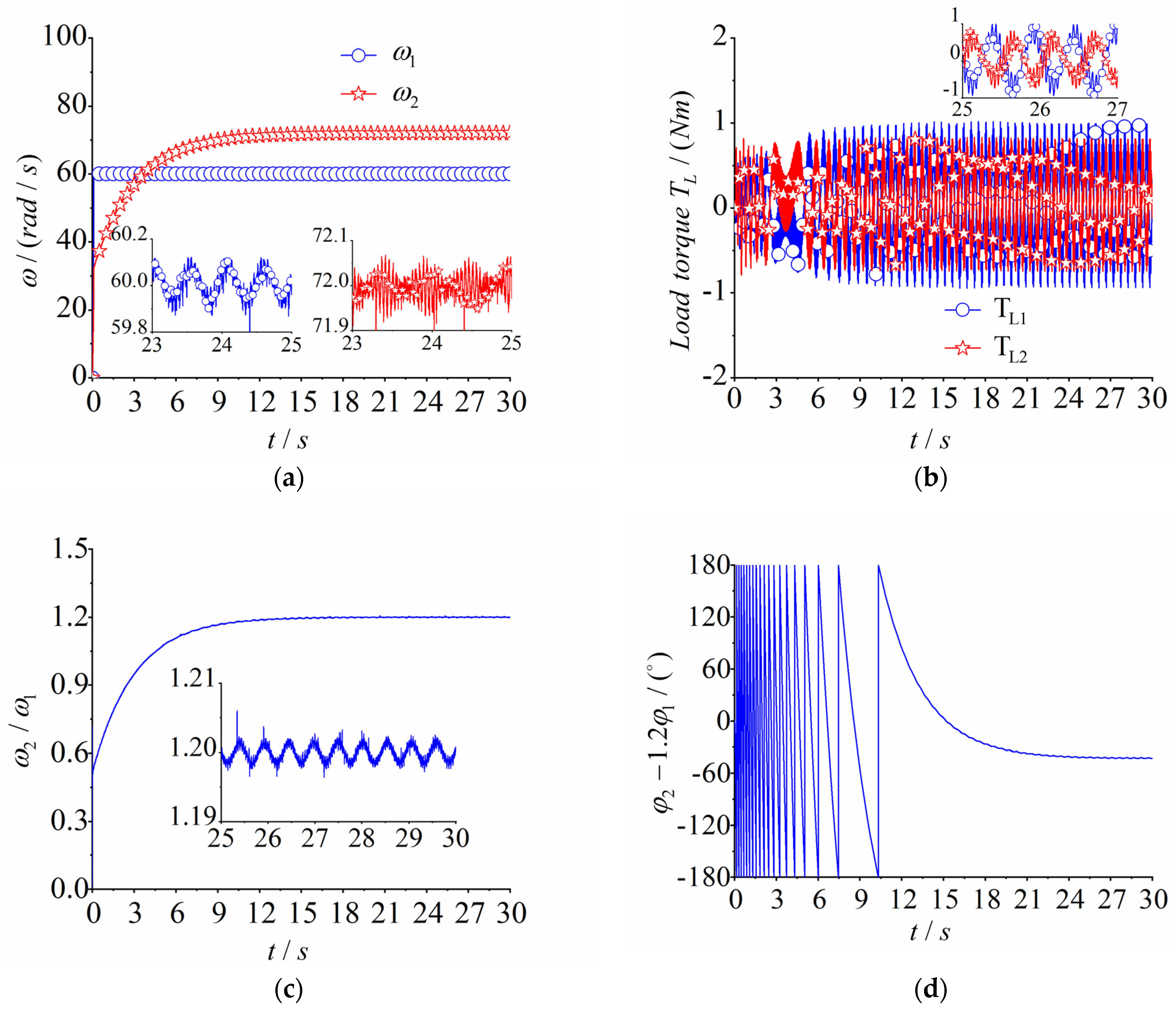
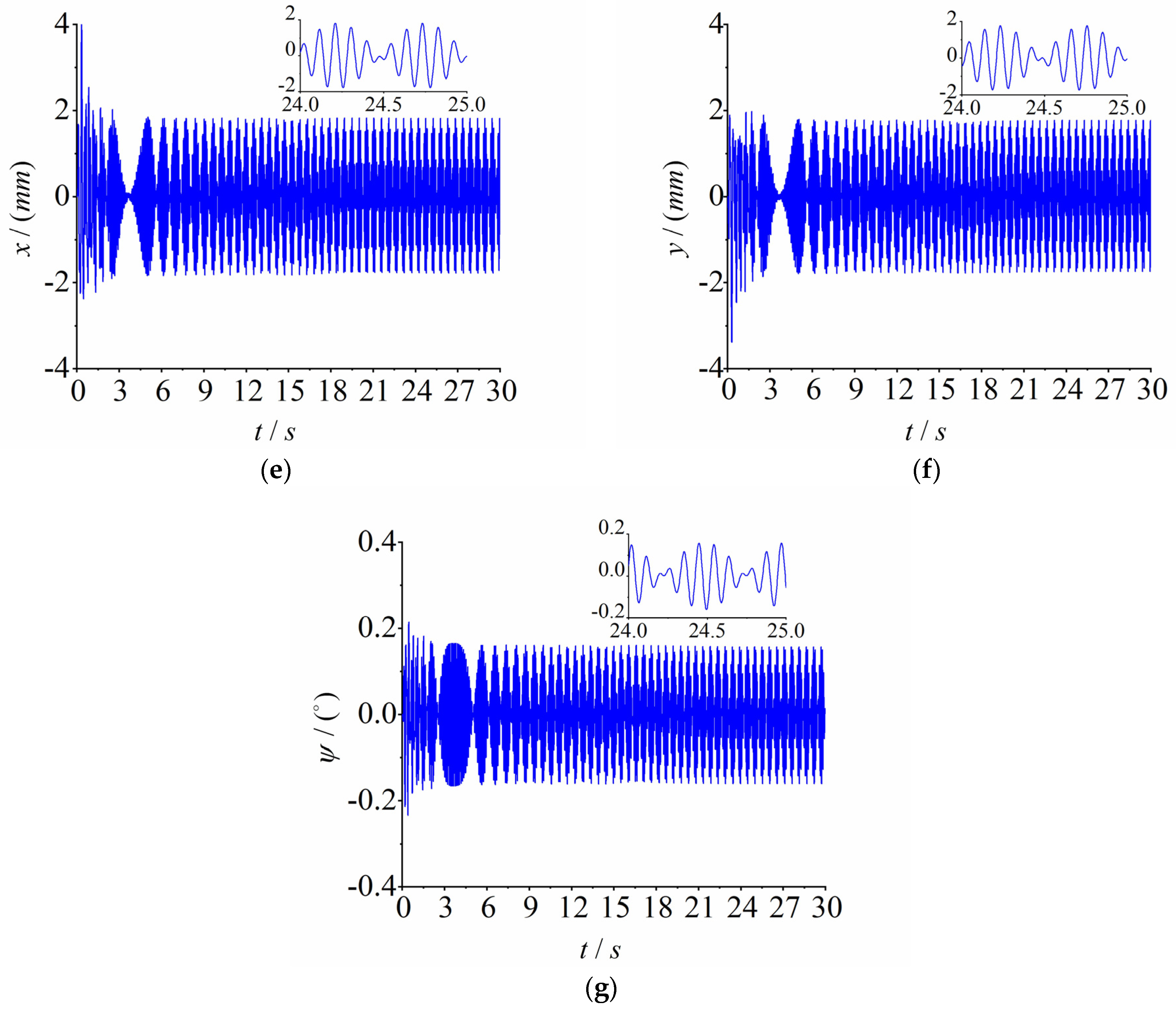
4.2. Numerical Simulation of the Multifrequency Composite Synchronization

Since multi-frequency self-synchronous motion with a fixed speed ratio was not realized, multi-frequency controlled synchronous motion with a fixed speed ratio was realized by introducing an improved BP PID control method. According to the master–slave control strategy utilized in this paper, the speed control of motor 1 and motor 2 was carried out first, followed by the speed control of the whole vibration system. After the speed of motor 1 was multiplied by the fixed speed ratio parameter n , we used the speed of motor 2 to track it. The simulation results are shown in Figure 9. In (a), the given speed of the main motor 1 is 60 rad/s, and the speed fluctuates in a small range after stabilization. Because of the fixed speed ratio parameter n = 1.5 , the speed of motor 2 stabilized at about 90 rad/s. (b) shows the load torque of the two induction motors. By enlarging the graph, we can see that the load torque values of the two induction motors were between −2 and 2, which means that the load torque values of both motors were less than the electromagnetic torque; thus, they can operate normally without motor blocking or motor destruction. To further demonstrate the accuracy of the speed control, as shown in (c), it is shown that the speed of motor 2 reached 1.5 times that of motor 1, which is further proof that the fixed-speed-ratio parameter reaches ω 2 / ω 1 = 1.5 . (d) shows the phase difference between the two excited motors. The value of the phase difference no longer varied constantly in the period range, but eventually converged to a constant value, which was determined by the chaotic synchronization at the initial over-resonance. (e–g) show the displacement responses of the vibrating system in three directions: x , y , and ψ , respectively. It can be clearly seen that, unlike the self-synchronous motion at the same frequency, they were no longer the standard sinusoidal curves, but the result of two different frequencies superimposed on each other. Therefore, in summary, the BP PID control method in this paper has good effectiveness and robustness for realizing the controlled synchronous motion of the vibration system; the vibration system achieved multi-frequency controlled synchronous motion with a given fixed speed ratio.
In order to prove the generality of the control method in this paper, controlled synchronization can be achieved under this dynamics model with any fixed speed ratio parameter n , so the fixed speed ratio parameter n was changed from 1.5 to 1.2 to obtain Figure 10. As shown in Figure 10a, the given speed of master motor 1 remained 60 rad/s. Because the fixed speed ratio parameter changed to 1.2, the speed of slave motor 2 changed to 72 rad/s. As can be seen from the enlarged graph, the speed values of both motors fluctuated up and down with their respective target values. Figure 10b shows the load torque of the two induction motors. Their values remained between −1 and 1 and did not exceed their own electromagnetic torque. This principle is the same as n = 1.5 in the above case. The speed ratio in Figure 10c also achieved a fixed speed ratio of ω 2 / ω 1 = 1.2 . The phase difference between the two excitation motors in (d) also gradually converged to a constant value. However, due to the different parameters of the fixed speed ratio, the response curves also varied accordingly, as shown in Figure 10e–g. It can be known that the control method based on this paper is able to achieve multi-frequency controlled synchronous motion with an arbitrary fixed speed ratio under the same dynamics model.

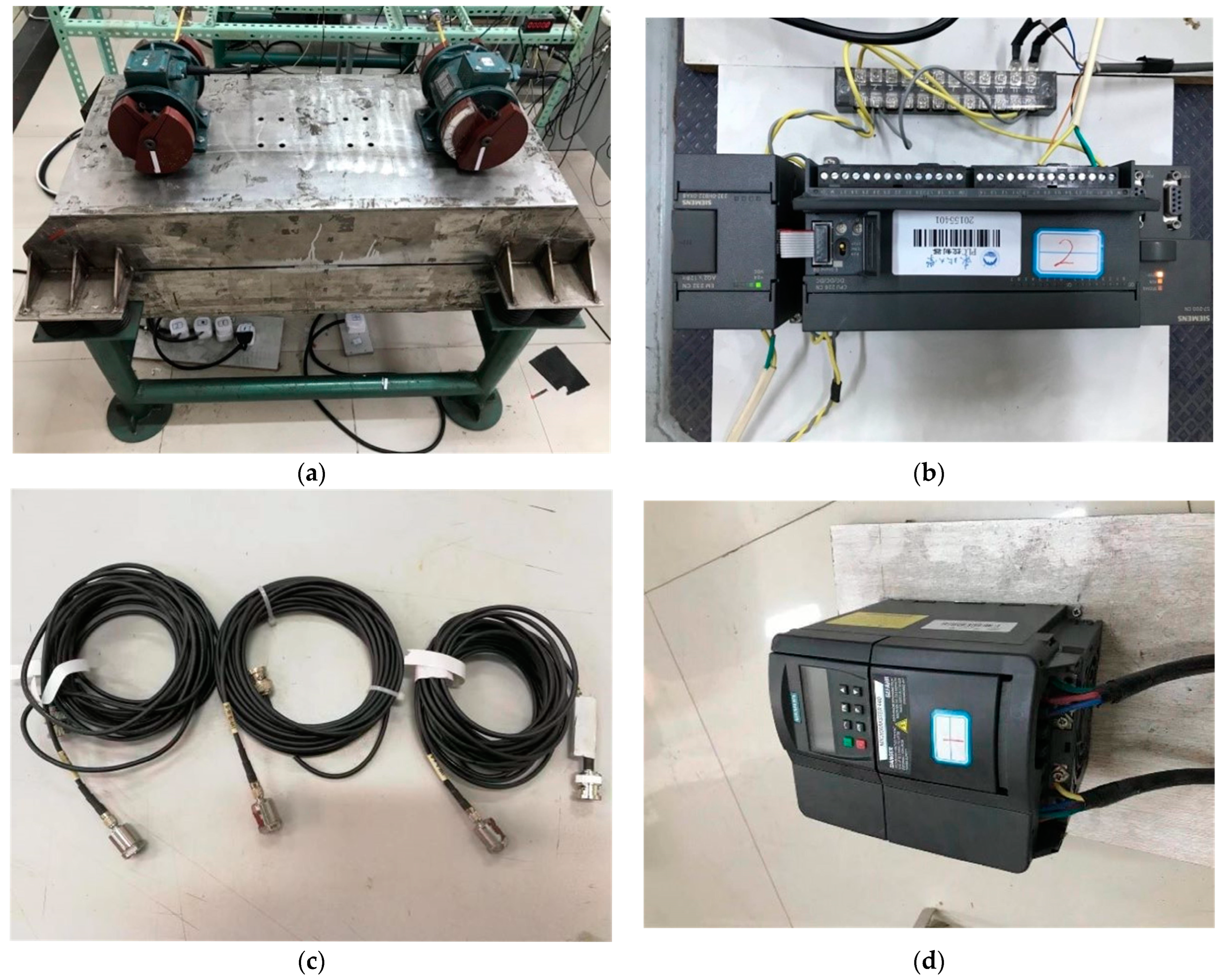
4.3. Experimental Verification

In order to verify the correctness of the simulation results, verification experiments were conducted on a vibration test stand, obtaining the same results as the simulation. The fixed speed ratio multi-frequency self-synchronization of the vibration system could not be achieved. After adding a control method, the fixed speed ratio multi-frequency controlled synchronous motion of the vibration system could be achieved. The parameters of the test stand and the motor parameters were the same as those in the simulation. First, we utilized an experimental shaking table and the experimental equipment shown in Figure 11. The speeds of the two induction motors in the experiment were controlled by two inverters, and the inverter model was chosen from Siemens MM440. The master–slave structure control strategy in the vibration system was implemented using a PLC (programmable logic controller), and the PLC model was Siemens S7-200. The acquisition of phase difference and angular velocity signals was carried out by means of pulse encoders. The response of the vibrating body and the transmission of the pulses were facilitated using three acceleration sensors, data acquisition and signal processing instruments from the Oriental Institute. Hall sensors were used to measure the phase difference between the two motors.

4.3.1. Experiment of Multifrequency Self-Synchronization

In this experiment, motor 1 on the right was the master motor, motor 2 on the left was the slave motor, and the given power supply frequencies of the two induction motors were 30 Hz and 45 Hz, respectively. The experimental results are shown in Figure 12. In (a), it is shown that the speeds of both motor 1 and motor 2 were slightly higher than the given speed value and fluctuated up and down more significantly. The phase difference between the two induction motors is given in (b), showing that the magnitude of the phase difference varied over the period and did not converge to a constant. The response curves of the vibrating system in the x and y directions are given in Figure 12c–e, respectively. Comparing these three plots with simulated plots (c–e) in Figure 8, we can observe that they have the same trend of variation. In summary, it can be concluded that the two induction motors do not achieve fixed-speed-ratio, multi-frequency, self-synchronous motion, which is consistent with the simulation results in Figure 8.

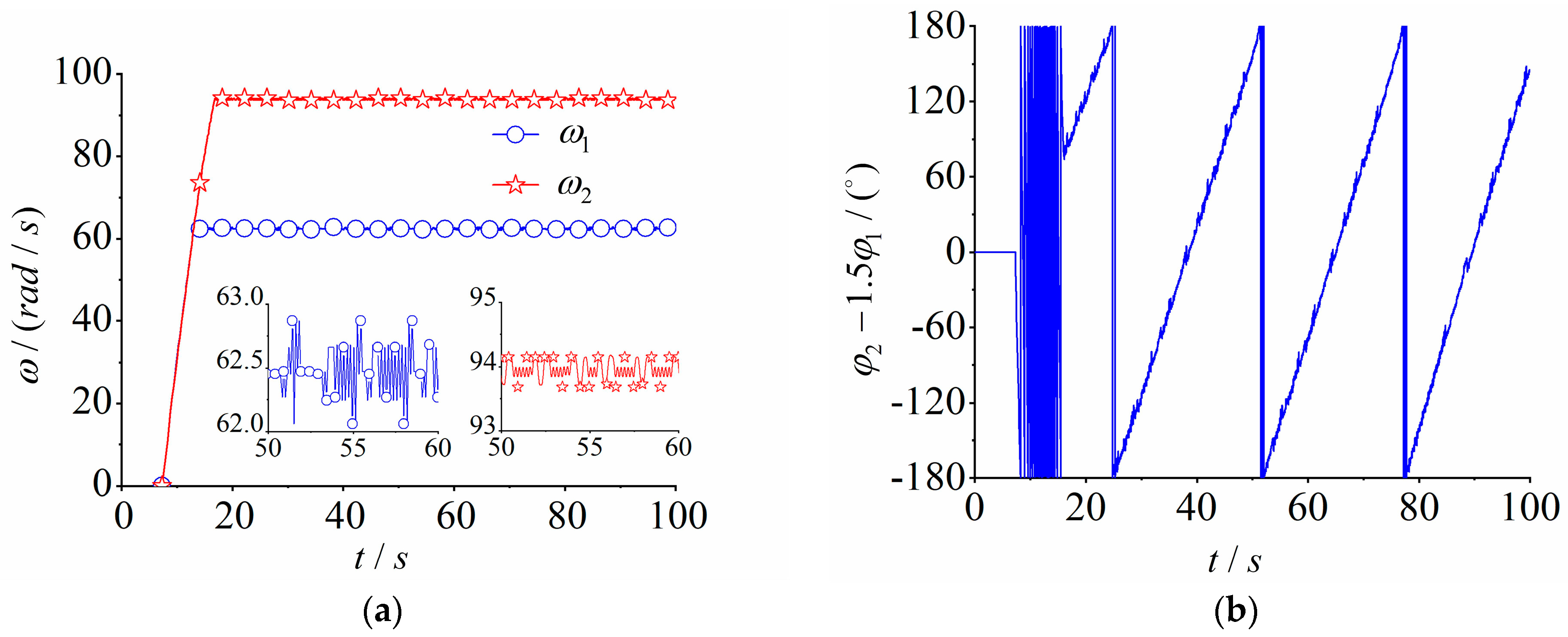
4.3.2. Experiment of Multifrequency Control Synchronization

The conclusion of the simulation aiming to achieve fixed-speed-ratio, multi-frequency control synchronization of two induction motors after adding a control method was verified by experiments. In this experiment, two induction motors rotated clockwise, and the power supply frequencies of the two induction motors, which were given by the frequency converter, were 27 Hz and 40.5 Hz, respectively. The PLC used a high-speed counter and recorded the number of pulse signals sent by the optical encoder through a timing interrupt, and then the high-speed counter was cleared and recounted. Thus, the speed tracking of induction motor 2 to induction motor 1 could be achieved. The experimental results are shown in Figure 13. In (a), it is evident that the speed of main motor 1 was stable, while motor 2 fluctuated slightly, but remained around the target value. In (b), it is shown that the phase difference between the two motors after stabilization converged to a constant value. In (c), it is demonstrated that the fixed speed ratio of the two induction motors fluctuated up and down at 1.5 times the center and remained stable. (d–f) are the response curves of the vibrating system, and comparing them with the simulation, it is clear that they showed the same trend. This shows that the simulation was consistent with the experimental results, which also proves that the vibration system achieved a fixed speed ratio ω 2 / ω 1 = 1.5 . In summary, the two induction motors in the experiment achieved synchronization with fixed-speed-ratio multi-frequency control.

5. Conclusions

The following conclusions can be drawn from the results of the simulations and experiments in this paper. Under the kinetic model shown in Figure 1, the phase difference of the two excitation motors with fixed speed ratios not equal to 1 was not a constant value. The fixed speed ratio multi-frequency self-synchronous motion of vibration systems could not be achieved, so the maximum amplitude and the required stable motion trajectory could not be realized in the screening process of the compound frequency vibrating screen. By incorporating a master–slave control structure and an improved BP neural-network-based PID control method, when the vibration system tended to stabilize, the speeds of the two induction motors were stabilized at the target value, achieving fixed-speed-ratio multi-frequency control synchronous motion of the vibration system. After changing the fixed speed ratio parameter, the above effect could also be achieved. Therefore, the application of the control method in this paper can achieve an increase in the amplitude of the compound frequency vibrating screen, which in turn is beneficial for the screening of materials and, at the same time, can meet the stable motion trajectory of the screen body. Thus, diversity of motion trajectory for a vibrating screen was realized, and the actual screening capacity of the vibrating screen was improved.

Author Contributions

Writing—original draft, X.Z.; Writing—review & editing, L.J. All authors have read and agreed to the published version of the manuscript.

Funding

This research was funded by [The Doctoral Research Foundation of Liaoning Science and Technology] grant number [2022-BS-187]. And the APC was funded by [The Doctoral Research Foundation of Liaoning Science and Technology].

Data Availability Statement

The data presented in this study are available on request from the corresponding author. The data are not publicly available due to the program which has been not yet completed.

Acknowledgments

This work acknowledgments the National Natural Science Foundation of China under Grant 12202285, and the Project of the Education Department of Liaoning Province under Grant LJKZ0258.

Conflicts of Interest

The authors declare no conflict of interest.

References

  1. Rodriguez, C.G.; Moncada, M.A.; Dufeu, E.E.; Razeto, M.I. Nonlinear Model of Vibrating Screen to Determine Permissible Spring Deterioration for Proper Separation. Shock Vib. 2016, 2016, 1–7. [Google Scholar] [CrossRef]
  2. Li, J.; Yu, W.; Kong, L.R. Synchronization characteristics of two vibrators in a novel hydraulic coupling system. Alex. Eng. J. 2022, 61, 11663–11676. [Google Scholar] [CrossRef]
  3. Hartig, J.; Shetty, A.; Conklin, D.R.; Weimer, A.W. Aeration and cohesive effects on flowability in a vibrating powder conveyor. Powder Technol. 2022, 408, 117724. [Google Scholar] [CrossRef]
  4. Wen, B.C.; Liu, S.Y.; He, Q. Theory and Dynamic Design Method of Vibrating Machinery; China Machine Press: Beijing, China, 2001. [Google Scholar]
  5. Wen, B.C.; Fan, J.; Zhao, C.Y.; Xiong, W.L. Vibratory Synchronization and Controlled Synchronization in Engineering; Science Press: Beijing, China, 2009. [Google Scholar]
  6. Klemiato, M.; Czubak, P. Event driven control of vibratory conveyors operating on the frahm’s eliminator basis. Arch. Metall. Mater. 2015, 60, 19–25. [Google Scholar] [CrossRef]
  7. Shagniev, O.B.; Tomchina, O.P.; Fradkov, A.L. Learning Speed-Gradient Synchronization Control of the Two-Rotor Vibration Setup. IFAC Pap. 2022, 55, 144–148. [Google Scholar] [CrossRef]
  8. Barathiraja, K.; Devaradjane, G.; Paul, J.; Rakesh, S.; Jamadade, G. Analysis of automotive transmission gearbox synchronizer wear due to torsional vibration and the parameters influencing wear reduction. Eng. Fail. Anal. 2019, 105, 427–443. [Google Scholar]
  9. Shen, G.; Chen, Z.; Wu, X.; Li, Z.; Tong, X. Stepwise shape optimization of the surface of a vibrating screen. Particuology 2021, 58, 26–34. [Google Scholar] [CrossRef]
  10. Blekman, I.I. Synchronization in Science and Technology; ASME Press: New York, NY, USA, 1988. [Google Scholar]
  11. Wen, B.C.; Guan, L.Z. Synchronization Theory and Debugging Method of Self-synchronous Vibration Motor. Min. Mach. 1979, 5, 35–45. [Google Scholar]
  12. Wen, B.C.; Zhang, H.; Liu, S.Y.; He, Q.; Zhao, C.Y. Theory and Techniques of Vibration Machinery and Their Applications; Science Press: Beijing, China, 2010. [Google Scholar]
  13. Inoue, J.C. On the Self-Synchronization of Mechanical Vibrators: Part 5, Shock Vibrator. J. Jpn. Soc. Mech. Eng. 1967, 70, 35–42. [Google Scholar] [CrossRef]
  14. Zhao, C.; Zhu, H.; Zhang, Y.; Wen, B. Synchronization of two coupled exciters in a vibrating system of spatial motion. Acta Mech. Sin. 2010, 26, 477–493. [Google Scholar] [CrossRef]
  15. Li, Y.; Ren, T.; Zhang, J.; Zhang, M. Synchronization of two eccentric rotors driven by one motor with two flexible couplings in a spatial vibration system. Math. Probl. Eng. 2019, 2019, 2969687. [Google Scholar] [CrossRef]
  16. Fang, P.; Wang, Y.; Hou, Y.; Wu, Y. Synchronous control of multi-motor coupled with pendulum in a vibration system. IEEE Access 2020, 8, 51964–51975. [Google Scholar] [CrossRef]
  17. Fang, P.; Hou, Y. Synchronization characteristics of a rotor-pendula system in multiple coupling resonant systems. Proc. Inst. Mech. Eng. Part C 2018, 232, 1802–1822. [Google Scholar] [CrossRef]
  18. Kong, X.; Zhang, X.; Chen, X.; Wen, B.; Wang, B. Synchronization analysis and control of three eccentric rotors in a vibration system using adaptive sliding mode control algorithm. Mech. Syst. Signal Process. 2016, 72-73, 432–450. [Google Scholar] [CrossRef]
  19. Kong, X.X.; Chen, C.Z.; Wen, B.C. Composite synchronization of three eccentric rotors driven by induction motors in a vibration system. Mech. Syst. Signal Process. 2018, 102, 158–179. [Google Scholar] [CrossRef]
  20. Kong, X.X.; Zhou, C.; Wen, B.C. Composite synchronization of four exciters driven by induction motors in a vibration system. Meccanica 2020, 55, 2107–2133. [Google Scholar] [CrossRef]
  21. Huang, Z.; Song, G.; Li, Y.; Sun, M. Synchronous control of two counter-rotating eccentric rotors in nonlinear coupling vibration system. Mech. Syst. Signal Process. 2019, 114, 68–83. [Google Scholar] [CrossRef]
  22. Huang, Z.; Song, G.; Zhang, Z.; Zhang, X. Control synchronization of two nonidentical homodromy exciters in nonlinear coupled vibration system. IEEE Access 2019, 7, 109934–109944. [Google Scholar] [CrossRef]
  23. Jin, C.; Cai, M.; Xu, Z. Dual-Motor Synchronization Control Design Based on Adaptive Neural Networks Considering Full-State Constraints and Partial Asymmetric Dead-Zone. Sensors 2021, 21, 4261. [Google Scholar] [CrossRef]
  24. Jia, L.; Wang, C.; Liu, Z.L. Multifrequency controlled synchronization of four inductor motors by the fixed frequency ratio method in a vibration system. Sci. Rep. 2023, 13, 2467. [Google Scholar] [CrossRef]
  25. Jia, L.; Liu, Z.L. Multifrequency composite synchronization of three inductor motors with the method of fixed speed ratio in a vibration system. Proc. Inst. Mech. Eng. 2023, 237, 254–268. [Google Scholar] [CrossRef]
  26. Zhang, X.L.; Wen, B.C.; Zhan, C.Y. Synchronization of three non-identical coupled exciters with the same rotating directions in a far-resonant vibrating system. J. Sound Vib. 2013, 332, 2300–2317. [Google Scholar] [CrossRef]
  27. Chen, J. Mathematical Model and Speed Adjustment System of Alternating Motors; National Defense Industry Press: Beijing, China, 1989. [Google Scholar]
Figure 1. Dynamic model of vibration system driven by two induction motors.
Machines 12 00097 g001
Figure 2. Function relation graph of r m and r l .
Machines 12 00097 g002
Figure 3. Function relation graph of l 0 and r l .
Machines 12 00097 g003
Figure 4. Control flow chart of the vibration system.
Machines 12 00097 g004
Figure 5. RFOC: rotor flux-oriented control.
Machines 12 00097 g005
Figure 6. Structure block diagram of PID controller based on BP neural network.
Machines 12 00097 g006
Figure 7. The structure of BP neural network.
Machines 12 00097 g007
Figure 8. Multifrequency self-synchronization with fixed speed ratio parameter of n = 1.5 , where α 0 = 0 . (a) Speed; (b) phase difference between motors 1 and 2; (c) response in the x direction; (d) response in the y direction; (e) response in the ψ direction.
Machines 12 00097 g008
Figure 9. Multifrequency control synchronization on fixed speed ratio parameter n = 1.5 , where α 0 = 0 . (a) Speed; (b) load torque; (c) speed ratio between motors 1 and 2; (d) phase differences between motor 1 and 2; (e) response in the x direction; (f) response in the y direction; (g) response in the ψ direction.
Machines 12 00097 g009aMachines 12 00097 g009b
Figure 10. Multifrequency control synchronization on fixed speed ratio parameter n = 1.2 , where α 0 = 0 . (a) Speed; (b) load torque; (c) speed ratio between motors 1 and 2; (d) phase differences between motor 1 and 2; (e) response in the x direction; (f) response in the y direction; (g) response in the ψ direction.
Machines 12 00097 g010aMachines 12 00097 g010b
Figure 11. Experimental equipment. (a) Vibration test bench; (b) programmable logic controller; (c) acceleration sensor; (d) frequency converter; (e) hall sensor; (f) signal acquisition instrument.
Machines 12 00097 g011aMachines 12 00097 g011b
Figure 12. Experiment on self-synchronization with fixed speed ratio parameter n = 1.5 , where α 0 = 0 . (a) Speed; (b) phase difference between motors 1 and 2; (c) response in the x direction; (d) response in the y direction; (e) response in the ψ direction.
Machines 12 00097 g012aMachines 12 00097 g012b
Figure 13. An experiment on control synchronization with fixed speed ratio parameter n = 1.5 , where α 0 = 0 . (a) Speed; (b) speed ratio between motors 1 and 2; (c) phase differences between motors 1 and 2; (d) response in the x direction; (e) response in the y direction; (f) response in the ψ direction.
Machines 12 00097 g013aMachines 12 00097 g013b
Table 1. The nomenclature table of the symbols.
SymbolExplanation
MThe total mass of the vibration system
mThe mass of the rigid body
m1, m2The eccentric rotor mass of 1 and 2 motors
rThe radius of eccentric rotor
l0The distance between the center of the body and the rotation center of the eccentric rotor
leThe equivalent rotation radius of the vibration system
JThe moment of inertia of the vibration system
JPThe moment of inertia of the rigid body
J1, J2The moment of inertia of two eccentric rotors
fx, fy, fψThe stiffness coefficients of the vibration system in the x, y, and ψ
f1, f2The damping coefficient of two induction motors
kx, ky kψThe spring stiffness of the vibration system in the x, y, and ψ directions
Te1, Te2The electromagnetic torque of two induction motors
TL1, TL2The load torque of two induction motors
Subscript sStator
Subscript rRotor
d-, q-The d- and q- axes in rotor field-oriented coordinate
i, u, RThe current, the voltage, and the resistance
LsSelf-inductance of the stator
LrSelf-inductance of the rotor
LmMutual inductance of the stator and rotor
TrA rotor time constant
LksStator leakage inductance
RksEquivalent stator resistance
npPole logarithm of induction motor
θSynchronous flux angle
ωMechanical angular velocity
ωsSynchronous electrical angular velocity
Table 2. Parameters of the two inductor motors.
ParametersMotor 1Motor 2
Rated power P/kW1.11.1
Pole pairs np33
Rated frequency f0/Hz5050
Rated voltage U/V220220
Rated speed n/(r/min)950950
Stator resistance Rs40.440.5
Rotor resistance referred Rr1212.813
Stator inductance Ls/H3.923.92
Rotor inductance referred Lr/H1.2221.222
Mutual inductance Lm/H1.1161.116
Rated flux linkage λ d r * /Wb0.980.98
Damping coefficients f1,2/(Nms/rad)0.0050.005
Table 3. Parameters of the vibration system.
ParametersValue
M/kg246
Jp/(kg.m2)43.3
kx/(N/m)129,332
ky/(N/m)105,334
kψ/(Nm/rad)30,715
fx/(Ns/m)615.5
fy/(Ns/m)618
fψ/(Nsm/rad)180.2
l0/m0.5
α/(°)0
θ1/(°)30
θ2/(°)150
m0/kg4
r/m0.05
Disclaimer/Publisher’s Note: The statements, opinions and data contained in all publications are solely those of the individual author(s) and contributor(s) and not of MDPI and/or the editor(s). MDPI and/or the editor(s) disclaim responsibility for any injury to people or property resulting from any ideas, methods, instructions or products referred to in the content.

